

Page 1
PuriCare
™
Ve rtical Flow Stations
Models
3830000
3830020
User’s Manual
LABCONCO CORPORATION
8811 PROSPECT AVENUE
KANSAS CITY, MO 64132-2696
800-821-5525, 816-333-8811
FAX 816-363-0130
E-MAIL labconco@labconco.com
HOME PAGE www.labconco.com
Labconco’s Mascot,
Labby the LABster
Register your product online at
www.labconco.com/productreg.html
or return the attached card and
receive FREE LabbyWear
™
!
Page 2

Copyright Information
Copyright © 2003 Labconco Corporation. All rights reserved.
Labconco Corporation
8811 Prospect Avenue
Kansas City, Missouri 64132
The information contained in this manual and the accompanying product are copyrighted and all rights are
reserved by Labconco Corporation. Labconco Corporation reserves the right to make periodic design
changes without obligation to notify any person or entity of such change.
PuriCare™ is a trademark of Labconco Corporation.
Warranty
Labconco provides a warranty on all parts and factory workmanship. The warranty includes areas of
defective material and workmanship, provided such defect results from normal and proper use of the
equipment.
The warranty for all Labconco products will expire one year from date of installation or two years from
date of shipment from Labconco, whichever is sooner, except the following:
• Purifier® Delta® Series Biological Safety Cabinets and PuriCare™ Vertical Flow Stations carry a
three-year warranty from date of installation or four years from date of shipment from Labconco,
whichever is sooner.
• Carts carry a lifetime warranty.
• Glassware is not warranted from breakage when dropped or mishandled.
This limited warranty covers parts and labor, but not transportation and insurance charges. In the event of a
warranty claim, contact Labconco Corporation or the dealer who sold you the product. If the cause is
determined to be a manufacturing fault, the dealer or Labconco Corporation will repair or replace all
defective parts to restore the unit to operation. Under no circumstances shall Labconco Corporation be
liable for indirect, consequential, or special damages of any kind. This statement may be altered by a
specific published amendment. No individual has authorization to alter the provisions of this warranty
policy or its amendments. Lamps and filters are not covered by this warranty. Damage due to corrosion or
accidental breakage is also not covered.
Limitation of Liability
The disposal and/or emission of substances used in connection with this equipment may be governed by
various federal, state, or local regulations. All users of this equipment are required to become familiar with
any regulations that apply in the user’s area concerning the dumping of waste materials in or upon water,
land, or air and to comply with such regulations. Labconco Corporation is held harmless with respect to
user’s compliance with such regulations.
Contacting Labconco Corporation
If you have questions that are not addressed in this manual, or if you need technical
assistance, contact Labconco’s Customer Service Department or Labconco’s Product
)
Visit Labconco’s web site at: http://www.labconco.com
Service Department at 1-800-821-5525 or 1-816-333-8811, between the hours of 7:00
a.m. and 6:00 p.m., Central Standard Time.
or email Labconco at: labconco@labconco.com.
Part #3794300, Rev A
ECO C722
Page 3

T
AABBLLEE
T
CHAPTER 1: INTRODUCTION 1
About This Manual 2
Typographical Conventions 3
CHAPTER 2: PREREQUISITES 5
Location Requirements 6
Exhaust Requirements 6
Electrical Requirements 7
Space Requirements 8
Overhead Clearance 8
CHAPTER 3: GETTING STARTED 9
Unpacking Your Vertical Flow Station 10
PuriCare Components 11
Preparing the Station for Operation 11
Exhaust System Requirements 12
Initial Certification 12
CHAPTER 4: THEORY OF OPERATION AND
HEPA Filters 14
Directional Airflow 15
Impellers and Motor/Blower 16
Speed Controls 16
Station Air Intakes (Grilles), Ductwork &
Air Balance Controls 17
Safety Precautions 17
CHAPTER 5: USING YOUR PURICARE 21
Operating the Sash 21
Working in Your PuriCare 23
CHAPTER 6: MAINTAINING YOUR PURICARE 26
Routine Maintenance Schedule 26
Service Operations 27
O
O
SAFETY PRECAUTIONS 13
FF
C
OONNTTEENNTTSS
C
Page 4

Downflow Velocities 30
Downflow Velocity Grid Patterns 30
Inflow Velocity Calculation – Primary Method 30
Inflow Velocity Calculation – Secondary Method 31
Speed Control Adjustments 32
Supply HEPA Filter Replacement 33
Exhaust HEPA Filter Replacement 35
Impeller and Motor/Blower Maintenance & Replacement 36
Diffuser Removal 38
Storage 39
CHAPTER 7: MODIFYING YOUR VERTICAL FLOW
STATION 40
Installing a Shelf 40
CHAPTER 8: TROUBLESHOOTING 42
APPENDIX A: VERTICAL FLOW STATION COMPONENTS 44
APPENDIX B: VERTICAL FLOW STATION DIMENSIONS 46
APPENDIX C: VERTICAL FLOW STATION
SPECIFICATIONS 47
Electrical Data 47
Impeller Specifications 47
Motor Specifications 48
APPENDIX D: PURICARE ACCESSORIES 51
Shelf Kit 51
APPENDIX E: QUICK CHART FOR THE PURICARE
VERTICAL FLOW STATIONS 52
APPENDIX F: REFERENCES 53
DECLARATION OF CONFORMITY 54
Page 5

C
HHAAPPTTEERR
C
I
NNTTRROODDUUCCTTIIOONN
I
Congratulations on your purchase of a Labconco
PuriCare Series Vertical Flow Station. Your PuriCare
product is designed to protect you, your product and
your laboratory environment from aerosols. It is the
result of Labconco’s years of experience manufacturing
laboratory equipment, and many of its features were
suggested to us by users like you.
The PuriCare offers many unique features to enhance
safety, performance and ergonomics. To take full
advantage of them, please acquaint yourself with this
manual and keep it handy for future reference. If you
are unfamiliar with how Vertical Flow Stations operate,
please review Chapter 4: Theory of Operation and
Safety Precautions before you begin working in the
station. Even if you are an experienced user, please
review Chapter 5: Using Your Vertical Flow Station; it
describes your PuriCare’s features so that you can use
the station efficiently.
1
1
Product Service 1-800-522-7658
1
Page 6

Chapter 1: Introduction
About This Manual
This manual is designed to help you learn how to
install, use, and maintain your Vertical Flow Station.
Instructions for installing optional equipment on your
station are also included.
Chapter 1: Introduction provides a brief overview of
the Vertical Flow Station, explains the organization of
the manual, and defines the typographical conventions
used in the manual.
Chapter 2: Prerequisites explains what you need to do
to prepare your site before you install your Vertical
Flow Station. Electrical and service requirements are
discussed.
Chapter 3: Getting Started contains the information
you need to properly unpack, inspect, install, and
certify your Vertical Flow Station.
Chapter 4: Theory Of Operation And Safety
Precautions explains how the PuriCare operates and the
appropriate precautions you should take when using the
station.
Chapter 5: Using Your PuriCare discusses the basic
operation of your station. Information on how to
prepare, use and shut down your PuriCare are included.
Chapter 6: Maintaining Your PuriCare explains how to
perform routine maintenance on your Vertical Flow
Station. Information on how to safely disinfect the
interior of your station and replace the lamps are
included.
Chapter 7: Modifying Your Vertical Flow Station
describes how to install the optional equipment on the
station.
Chapter 8: Troubleshooting contains a table of
problems you may encounter while using your Vertical
Flow Station including the probable causes of the
problems and suggested corrective actions.
2
Product Service 1-800-522-7658
Page 7
Appendix A: Vertical Flow Station Components
contains labeled diagrams of all of its components.
Appendix B: Vertical Flow Station Dimensions contains
comprehensive diagrams showing all of the dimensions
for the PuriCare model.
Appendix C: Vertical Flow Station Specifications
contains the electrical requirements for the Vertical
Flow Station. Wiring diagrams for both the 115V and
230V models are also included.
Appendix D: PuriCare Accessories lists the part
number and descriptions of all of the accessories
available for your Vertical Flow Station.
Appendix E: Quick Chart for the PuriCare Vertical
Flow Station provides useful operating specifications.
Appendix F: References lists the various resources
available that deal with biosafety.
Chapter 1: Introduction
Typographical Conventions
Recognizing the following typographical conventions
will help you understand and use this manual:
• Book, chapter, and section titles are shown in italic
type (e.g., Chapter 3: Getting Started).
• Steps required to perform a task are presented in a
numbered format.
• Comments located in the margins provide
suggestions, reminders, and references.
• Critical biosafety information is presented in
boldface type in paragraphs that are preceded by the
biosafety icon. Failure to comply with the
information following a biosafety icon may result in
illness or death.
Product Service 1-800-522-7658
3
Page 8
Chapter 1: Introduction
!
)
115V
230V
• Critical information is presented in boldface type in
paragraphs that are preceded by the exclamation
icon. Failure to comply with the information
following an exclamation icon may result in injury
to the user or permanent damage to your Vertical
Flow Station.
• Critical information is presented in boldface type in
paragraphs that are preceded by the wrench icon.
These operations should only be performed by a
trained certifier or contractor. Failure to comply
with the information following a wrench icon may
result in injury to the user or permanent damage to
your Vertical Flow Station.
• Important information is presented in capitalized
type in paragraphs that are preceded by the pointer
icon. It is imperative that the information contained
in these paragraphs be thoroughly read and
understood by the user.
• Information that is specific to a particular model of
Vertical Flow Station is preceded by a number icon.
The 115V icon indicates the text is specific to the
115 volt models. The 230V icon indicates the text
is specific to the 230 volt models.
4
Product Service 1-800-522-7658
Page 9

C
HHAAPPTTEERR
C
P
RREERREEQQUUIISSIITTEESS
P
Before you install your Vertical Flow Station, you need
to prepare your site for installation. Carefully examine
the location where you intend to install your station.
You must be certain that the area is level and of solid
construction. In addition, a dedicated source of
electrical power must be located near the installation
site.
Carefully read this chapter to learn:
• the location requirements for your installation
site.
• the electrical power requirements for your
installation site.
• the exhaust requirements for your installation
site.
• the space requirements for your installation site.
Refer to Appendix C: Vertical Flow Station
Specifications for complete station electrical and
environmental conditions, specifications and
requirements.
2
2
Product Service 1-800-522-7658
5
Page 10
Chapter 2: Prerequisites
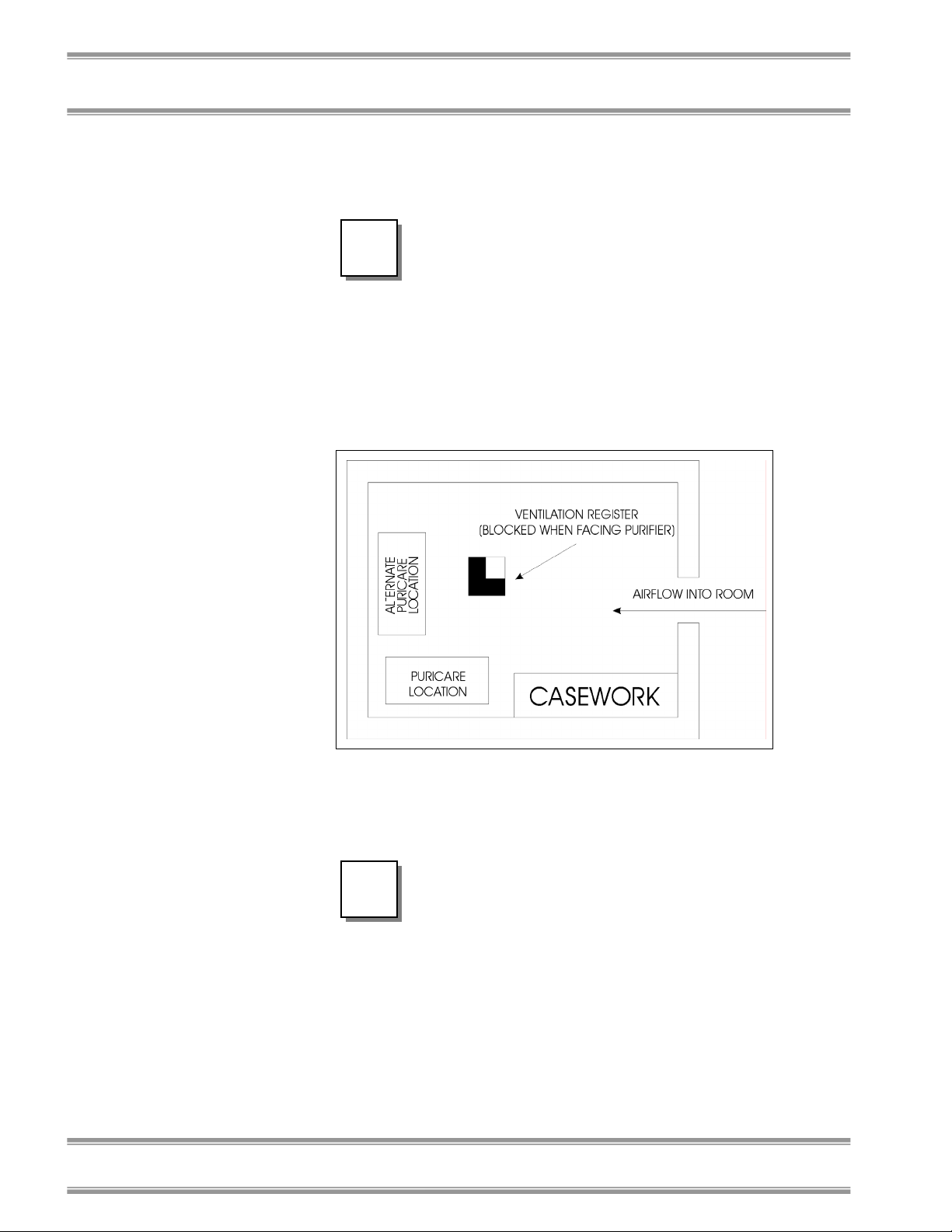
Location Requirements
The PuriCare should be located away
!
from traffic patterns, doors, fans,
ventilation registers, fume hoods and
any other air-handling device that
could disrupt its airflow patterns. All
windows in the room should be closed.
Figure 2-1 shows the optimum
location for the PuriCare.
Figure 2-1
6
Exhaust Requirements
THE VERTICAL FLOW STATION
DISCHARGES ITS FILTERED
)
EXHAUST AIR UNDERNEATH THE
UNIT. IT SHOULD BE PLACED AT
LEAST 12 INCHES AWAY FROM
ANY VERTICAL OBSTRUCTION TO
OPERATE PROPERLY.
Product Service 1-800-522-7658
Page 11
Electrical Requirements
The different PuriCare models have the following
electrical requirements:
Model # Requirements
38300- 00-09 115 VAC, 60 Hz, 12 Amps
38300- 20-29 230 VAC, 50 Hz, 6 Amps
All PuriCare Stations with model numbers ending in –
00 to –09 are designed for operation at 115 volts, 60Hz,
alternating current. PuriCare Stations with model
numbers ending in –20 to –29 are designed for
operation at 230 +/- 20 volts, 50 Hz alternating current.
A dedicated outlet with a circuit breaker rated at 20
Amps for 115 volt models and 10 Amps for 230 volt
models, should be located within 10 feet of the station.
Always follow the plug
manufacturer’s instructions for the
!
115V
proper assembly and testing of the
plug and power cord.
THE ELECTRICAL OUTLETS OF
THE 115 VOLT PURICARE IS
PROTECTED BY A GROUND FAULT
INTERRUPTER CIRCUIT (GFIC).
LABCONCO DOES NOT
RECOMMEND INSTALLING A GFIC
ON THE OUTLET THAT THE
PURICARE PLUGS INTO.
Table 2-1
Chapter 2: Prerequisites
Product Service 1-800-522-7658
7
Page 12

Chapter 2: Prerequisites
Space Requirements
The dimensions for the different models are shown in
Appendix B: Vertical Flow Station Dimensions.
Overhead Clearance
In order for the Vertical Flow Station to operate
properly, at least six inches (150 mm) clearance from
any overhead obstructions is required when the station
is in its final operating position.
8
Product Service 1-800-522-7658
Page 13

C
HHAAPPTTEERR
C
G
EETTTTIINNGG
G
Now that the site for your Vertical Flow Station is
properly prepared, you are ready to unpack, inspect,
install, and certify it. Read this chapter to learn how to:
• unpack and move your PuriCare.
• set up the station.
• connect the electrical supply source.
• arrange certification.
Depending upon which model you are installing, you
may need common tools in addition to a 3/4" wrench, a
flat-blade screwdriver, and a Phillips screwdriver.
The PuriCare models weigh
approximately 450 lbs. (205 kg). The
!
carton allows for lifting with a
mechanical lift truck or floor jack.
S
S
3
3
TTAARRTTEEDD
Product Service 1-800-522-7658
9
Page 14

Chapter 3: Getting Started
The United States
Interstate Commerce
Commission rules
require that claims be
filed with the delivery
carrier within fifteen (15)
days of delivery.
Unpacking Your Vertical
Flow Station
Carefully unpack your PuriCare and inspect it for
damage that may have occurred in transit. If your unit
is damaged, notify the delivery carrier immediately and
retain the entire shipment intact for inspection by the
carrier.
DO NOT RETURN GOODS
WITHOUT THE PRIOR
)
Do not discard the carton or packing material for your
PuriCare until you have checked all of the components
and installed and tested the unit.
!
AUTHORIZATION OF LABCONCO.
UNAUTHORIZED RETURNS WILL
NOT BE ACCEPTED.
IF YOUR STATION WAS DAMAGED
IN TRANSIT, YOU MUST FILE A
CLAIM DIRECTLY WITH THE
FREIGHT CARRIER. LABCONCO
CORPORATION AND ITS DEALERS
ARE NOT RESPONSIBLE FOR
SHIPPING DAMAGES.
Do not remove the PuriCare from its
shipping skid until it is ready to be
placed into its final location. Move the
unit by placing a flat, low dolly under
the shipping skid, or by using a floor
jack.
Do not move the station by tilting it
onto a hand truck.
10
Product Service 1-800-522-7658
Page 15

PuriCare Components
Labconco manufactures Vertical Flow Stations for use
with 115 volts or 230 volts.
Locate the station model you received in the following
group of tables. Verify that the components listed are
present and undamaged.
Catalog # PuriCare Description
3830000 Vertical Flow Station, 115 VAC, 60 Hz
3830020 Vertical Flow Station, 230 VAC, 50 Hz
Plus the Following:
Part # Component Description
3794300 User’s Manual
Power Cord
(4) Caster Wheels
(8) Washers
(4) Lock Washers
(4) Acorn Nuts
If you did not receive one or more of the components
listed for your PuriCare, or if any of the components are
damaged, contact Labconco Corporation immediately
for further instructions.
Chapter 3: Getting Started
Preparing the Station for
Operation
ASSEMBLY INSTRUCTIONS FOR
)
Product Service 1-800-522-7658
THE STATION (LABCONCO P/N
1058300) ARE ATTACHED TO THE
SASH OF THE PURICARE. IF THESE
INSTRUCTIONS ARE MISSING OR
UNCLEAR, CONTACT LABCONCO
AT 800-821-5525.
11
Page 16

Chapter 3: Getting Started
Exhaust System
Requirements
The Vertical Flow Station discharges its HEPA filtered
exhaust air beneath the unit.
Maintain at least 12 inches clearance
!
between the station and any vertical
obstruction on all sides of the unit.
Initial Certification
Prior to use, all PuriCare stations should be certified by
a qualified certifier. Under normal operating
conditions, the PuriCare stations should be recertified at
least annually or when serviced. The certifier should
perform the following tests:
• HEPA Filter Leak Tests
• Downflow Velocity Profile Test*
• Inflow Volume Test
• Airflow Smoke Patterns
*There is no tolerance on the downflow
profile values.
If you have any questions regarding certification
agencies or need assistance in locating one, contact
Labconco’s Product Service Department at 1-800-5227658 or 816-333-8811.
12
Product Service 1-800-522-7658
Page 17

C
HHAAPPTTEERR
C
T
HHEEOORRY
T
O
PPEERRAATTIIOONN
O
S
AAFFEETTYY
S
P
RREECCAAUUTTIIOONNSS
P
The Vertical Flow Station operates using the following
principles:
• Filtration and retention of particulates by High
Efficiency Particulate Air (HEPA) filters
Directional airflow
The major components in the Vertical Flow Station are:
• The HEPA filters
• The impellers and motor/blower to force air
through the unit
• A speed controls for the impellers and motor
• Station air intakes (grilles)
Y
O
O
4
4
F
F
A
A
NNDD
Product Service 1-800-522-7658
13
Page 18
Chapter 4: Theory Of Operation And Safety Precautions
HEPA Filters
HEPA filters are disposable, dry-type particulate filters.
The filter material or media is typically made of
borosilicate microfibers that are made into a thin sheet,
in a process similar to the production of paper. This
sheet is folded, or pleated to increase its surface area.
The pleats are held in place by aluminum diffusers or
by beads of glue that add rigidity to the media pack.
The media pack is then set into a suitable frame, and the
perimeter sealed to the filter frame, as shown in Figure
4-1.
The HEPA filter media is very fragile.
Do not touch or contact the media
!
!
surface. If you think the surface of a
HEPA filter is damaged, DO NOT
USE THE STATION. Have the
HEPA filter integrity tested by a
qualified certifier before using the
station.
HEPA Filters are only effective
against particulate material. Gases
will pass through the filter.
14
Product Service 1-800-522-7658
Page 19

Chapter 4: Theory Of Operation And Safety Precautions
Figure 4-1
Directional Airflow
Directional airflow plays a key role in the Vertical Flow
Station’s performance. Sterile, HEPA filtered air flows
downward throughout the work area, protecting the
animals inside from external and cross contamination.
All of this “supply” air and some room air is drawn into
the front of the station at the grille. This “curtain” of air
makes it difficult for aerosols to escape out of the work
area and into the outside environment.
Product Service 1-800-522-7658
15
Page 20

Chapter 4: Theory Of Operation And Safety Precautions
Figure 4-2
Impellers and Motor/Blower
The Vertical Flow Station uses two air handling
systems to direct air through it. In the top of the station
twin motorized impellers draw room air in through
prefilters and then force the air through the upper
(supply) HEPA filter. Below the worksurface there are
another set of prefilters, a heavy duty motor blower and
the exhaust HEPA filter.
Speed Controls
The speed controls should only be
!
adjusted by a qualified certifier.
16
Product Service 1-800-522-7658
Page 21

Chapter 4: Theory Of Operation And Safety Precautions
The speed controls are electronic circuits that allow the
certifier to set the speed of the motors by adjusting their
voltage. The PuriCare speed controls are rated for 10
Amps current each, far in excess of the motor's normal
current draw, to allow for greater reliability.
Station Air Intakes (Grilles),
Ductwork and Air Balance
Controls
The station’s containment and performance are affected
by the location, size, and pattern of the grilles at the
front and rear of the work area.
Never block or obstruct the grilles of
!
The internal ductwork of the PuriCare conveys the air
from the work area to the blower, and then from the
blower to the filters. The exhaust filter plenum of the
PuriCare is unique in the industry, utilizing perfect
manifold technology to deliver a more uniform airflow
to the exhaust HEPA filter, optimizing filter loading
and operational life.
the PuriCare.
Safety Precautions
The PuriCare Vertical Flow Station is
NOT a biosafety cabinet. Do not use
this device for the containment of
biohazardous, toxic, flammable, or
explosive materials. If you have
questions regarding the operation of
this device, contact Labconco at 800821-5525 or www.labconco.com.
Product Service 1-800-522-7658
17
Page 22

Chapter 4: Theory Of Operation And Safety Precautions
HEPA filters are only effective for the
!
!
entrapment of particulate matter.
Manipulations which generate gases
or vapors, i.e., toxic chemicals or
radionuclides, should not be
performed in this station.
The PuriCare Vertical Flow Station
should be certified by a qualified
certification technician before its
initial use. The station should be
recertified whenever it is relocated,
serviced or at least annually
thereafter.
Some components of the PuriCare
Vertical Flow Station should only be
serviced by a qualified certification
technician. Some internal components
of the PuriCare may become
contaminated with allergenic
materials during operation of the unit.
Only experienced personnel
competent in decontamination
procedures should decontaminate the
station before servicing contaminated
components. If you have any
questions regarding certification
agencies, or need assistance in locating
one, contact Labconco’s Product
Service Department at 800-522-7658
or 816-333-8811.
Ensure that the unit is connected to
electrical service in accordance with
local and national electrical codes.
Failure to do so may create a fire or
electrical hazard. Do not remove or
service any electrical components
without first disconnecting the
PuriCare from electrical service.
18
Product Service 1-800-522-7658
Page 23

)
Chapter 4: Theory Of Operation And Safety Precautions
Avoid the use of flammable gases or
solvents in the PuriCare. Care must
be taken to ensure against the
concentration of flammable or
explosive gases or vapors. An open
flame should NOT be used in the
PuriCare. Open flames may disrupt
the airflow patterns in the station,
burn the HEPA filter and/or damage
the filter’s adhesive. Gases under high
pressure should not be used in the
PuriCare station, as they may disrupt
the airflow patterns of the station.
The surface of the HEPA filters are
fragile and should not be touched.
Care must be taken to avoid
puncturing either HEPA filter during
installation or normal operation. If
you suspect that a HEPA filter has
been damaged, DO NOT use the
station; contact a local certification
agency or Labconco at 800-821-5525
or 816-333-8811 for recertification
information.
THE HEPA FILTERS IN THE
PURICARE STATION WILL
GRADUALLY ACCUMULATE
AIRBORNE PARTICULATE
MATTER FROM THE ROOM AND
FROM WORK PERFORMED IN THE
STATION. THE RATE OF
ACCUMULATION WILL DEPEND
UPON THE CLEANLINESS OF THE
ROOM AIR, THE AMOUNT OF TIME
THE STATION IS OPERATING AND
THE NATURE OF WORK BEING
DONE IN THE STATION.
Product Service 1-800-522-7658
19
Page 24

Chapter 4: Theory Of Operation And Safety Precautions
Proper operation of the station
depends largely upon the station’s
!
)
location and the operator’s work
habits. Consult the Installation and
Normal Operation sections of this
manual for further details.
WHEN SURFACE DISINFECTING
THE PURICARE STATION:
• AVOID SPLASHING THE
DISINFECTING SOLUTION ON SKIN
OR CLOTHING.
• ENSURE ADEQUATE
VENTILATION.
• CAREFULLY FOLLOW THE
MANUFACTURER’S SAFETY
INSTRUCTIONS WHEN HANDLING
DISINFECTANTS AND ALWAYS
DISPOSE OF DISINFECTING
SOLUTIONS IN ACCORDANCE
WITH LOCAL AND NATIONAL
LAWS.
DO NOT ALLOW DISINFECTANTS
WITH FREE CHLORINE TO
CONTACT THE STAINLESS STEEL
COMPONENTS OF THE PURICARE
FOR A LONG PERIOD OF TIME.
FREE CHLORINE WILL CORRODE
STAINLESS STEEL AFTER
EXTENDED CONTACT.
The electrical receptacle cover,
because of its construction, may be
difficult to surface decontaminate. In
the event of gross contamination, the
cover should be removed, sterilized
and/or decontaminated as required
and discarded. The receptacle cover
should then be replaced with the
repair part listed in Appendix A:
PuriCare Components.
20
Product Service 1-800-522-7658
Page 25

C
HHAAPPTTEERR
C
U
SSIINNG
U
P
UURRI
P
Operating the Sash
The sash of the Vertical Flow Station can be locked in
the full open position. To lock the sash open:
1. Grasp the bottom edge of the sash, and pivot it up
until the sash is fully opened.
2. Locate the sash locking bolt on the inside left side
of the sash, as shown in Figure 5-1.
3. Restrain the sash by aligning the bolt with the hole
in the left side wall of the station, and pressing the
bolt to the left until it engages the hole.
4. To release the sash, support the bottom edge while
pulling the bolt to the right. Allow the sash to pivot
down to its closed position, ensuring that the sash is
set in the closed position.
I
G
C
C
Y
Y
AARREE
5
5
OOUURR
Product Service 1-800-522-7658
21
Page 26

Chapter 5: Using Your PuriCare
Figure 5-1
22
The sash must be completely closed
!
5. Turn the blower and light switches to the 'On'
position, as shown in Figure 5-2.
for the PuriCare to contain properly.
Product Service 1-800-522-7658
Page 27
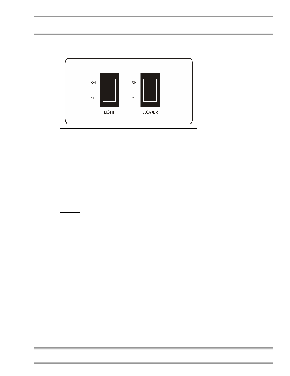
Figure 5-2
Working In Your PuriCare
Planning
• Thoroughly understand procedures and
equipment required before beginning work.
• Arrange for minimal disruptions, such as room
traffic or entry into the room while the station is
in use.
Start-up
• Turn on fluorescent light and station blower.
• Check the return air grilles for obstructions, and
note the pressure gauge reading.
• Allow the station to operate unobstructed for 5
minutes.
• Wash hands and arms thoroughly with
germicidal soap.
• Wear a long sleeved lab coat with knit cuffs and
over-the- cuff rubber gloves. Use protective
eyewear. Wear a protective mask if appropriate.
Wipe-Down
• Pivot the sash to its full open position.
• Wipe down the interior surfaces of the station
with 70% ethanol, or a suitable disinfectant, and
allow to dry.
• Slowly close the sash.
Chapter 5: Using Your PuriCare
Product Service 1-800-522-7658
23
Page 28

Chapter 5: Using Your PuriCare
Loading Materials and Equipment
Work Techniques
Final Purging
Unloading Materials and Equipment
• Only load the materials required for the
procedure. Do not overload the station.
• Do not obstruct the grilles on the front, back or
sides of the work area.
• Large objects should not be placed close
together.
• Keep all materials at least 4 inches inside of the
sash, and perform all contaminated operations
as close to the center of the work area as
possible.
• Segregate all clean and contaminated materials
in the work area.
• Arrange materials to minimize the movement of
contaminated materials into clean areas.
• Keep all discarded contaminated material to one
zone work area.
• Avoid the use of an open flame.
• Use proper aseptic technique.
• Avoid using techniques or procedures that
disrupt the airflow patterns of the station.
• If there is a spill or splatter during use, all
objects in the station should be surface
decontaminated before removal. Thoroughly
disinfect the working area of the station WHILE
IT IS STILL IN OPERATION. This will
prevent the release of contaminants from the
station.
• Upon completion of work, the station should be
allowed to operate for two to three minutes
undisturbed, to purge airborne contaminants
from the work area.
• Objects in contact with contaminated material
should be surface decontaminated before
removal from the station.
• All open trays or containers should be covered
before being removed from the station.
24
Product Service 1-800-522-7658
Page 29

Wipe-Down
• Wipe down the interior surfaces of the station
with 70% ethanol, or a suitable disinfectant, and
allow to dry.
• Periodically lift the work surface and wipe
down the area beneath it.
• Inspect the prefilters located beneath the work
surface, beneath the work pan. Replace them if
necessary
• Dispose of rubber gloves appropriately, and
have lab coat laundered properly.
• Wash hands and arms thoroughly with
germicidal soap.
Shutdown
• Turn off the fluorescent light and station blower,
close the sashes.
Chapter 5: Using Your PuriCare
Product Service 1-800-522-7658
25
Page 30

C
HHAAPPTTEERR
C
M
P
Now that you have an understanding of how to work in
the Vertical Flow Station, we will review the suggested
maintenance schedule and the common service
operations necessary to maintain your PuriCare for
peak performance.
AAIINNTTAAIINNIINNG
M
C
P
!
UURRI
I
AARREE
C
Many of the service operations should
be performed only by trained and
experienced certification technicians
after the station has been properly
decontaminated. DO NOT attempt to
perform these operations if you are
not properly trained. The service
operations that require qualified
certifiers are preceded by the wrench
icon.
6
6
G
Y
Y
OOUURR
26
Routine Maintenance
Schedule
Weekly
Product Service 1-800-522-7658
• Using 70% ethanol, or a suitable disinfectant,
surface disinfect the inside of the station, and
the work surface.
Page 31

• Using an appropriate optical glass cleaner and
cloth, clean the sash.
• Operate the station blowers, noting the pressure
readings in an operational log.
• Lift the work surface and inspect the prefilters.
Monthly (or more often as required)
• Using a damp cloth, clean the exterior surfaces
of the station, particularly the front, back and
top of the unit, to remove any accumulated dust.
• Disinfect and lift the work surface. Surface
disinfect the lower plenum with a solution of
70% ethanol, or a suitable disinfectant. Check
the prefilters for retained materials.
• Replace the prefilters as needed.
• All weekly activities.
Annually
• Have the station recertified by a qualified
certification technician.
• All monthly activities.
Biannually
• Replace the fluorescent lamp.
Chapter 6: Maintaining Your PuriCare
Service Operations
Work Surface Removal:
1. Loosen and remove the three thumbscrews located
at the front of the work surface. Only loosen the
three thumbscrews on the back of the work surface.
2. Lift the front edge of the work surface up and pull it
out of the station work area.
Prefilter Removal and Cleaning:
The prefilters may be contaminated
!
Product Service 1-800-522-7658
with allergenic material. Take
appropriate precautions when
removing and handling the prefilters
to prevent exposure. The prefilters
are disposable and cannot be cleaned.
27
Page 32

Chapter 6: Maintaining Your PuriCare
Upper Prefilter Removal:
1. Loosen the nuts that secure the two upper prefilter
brackets as shown in Figure 6-1.
2. Swing the upper prefilter brackets until the
prefilters can be lifted out of the top of the units.
3. Replace the prefilter elements, ensuring the air flow
direction arrow on the prefilter frame points down.
Figure 6-1
28
Lower Prefilter Removal:
1. Remove the work surface as described earlier.
2. Loosen the nuts that secure the two lower prefilter
brackets as shown in Figure 6-2.
3. Swing the lower prefilter brackets until the
prefilters can be lifted out of the unit.
Product Service 1-800-522-7658
Page 33

Chapter 6: Maintaining Your PuriCare
4. Replace the prefilter elements, ensuring the air flow
direction arrow on the prefilter frame points down.
Figure 6-2
Changing the Fluorescent Lamp:
1. Unplug the station.
2. Swing up the sash.
3. Remove the fluorescent lamp by rotating it 90
degrees and pulling it straight down and out of its
sockets.
3. Install the new lamp by reversing the removal
procedure.
Resetting a Circuit Breaker:
To reset any of the circuit breakers located on the back
of the unit near the power cord outlet, depress the white
button until it sets.
Product Service 1-800-522-7658
29
Page 34

Chapter 6: Maintaining Your PuriCare
!
Downflow Velocities
The service operations listed in the
rest of this chapter should only be
performed by a qualified certifier.
The average downflow velocity for all Vertical Flow
Stations should be set at 50-55 FPM.
Downflow Velocity Grid
Patterns
The downflow velocity test grid for all Vertical Flow
Stations is as follows:
The perimeter of the down test grid is 6.00 inches from
the side walls and 6.00 from the rear of the work area.
The grid consists of three rows, 5.95 inches apart, from
the back to the front, with eight test points on each row,
spaced 5.21 inches apart. All points are read at the
bottom edge of the sash.
Inflow Volume Calculation -
30
Primary Method
The Inflow Volume can be measured directly, using a
Direct Inflow Measurement (DIM) meter, using the
following method:
1. Turn the station off and raise the sash.
2. Remove the work surface and the lower prefilters as
described earlier.
3. Using rigid cardboard, or fiberboard, cut two
patterns as shown in Figure 6-3.
4. Place the solid pattern over the prefilter hole
directly above the blower. Seal the pattern to the
prefilter shelf with duct tape if necessary.
Product Service 1-800-522-7658
Page 35

Chapter 6: Maintaining Your PuriCare
5. Place the pattern with the hole over the other
prefilter hole. Seal the pattern to the prefilter shelf
if necessary.
6. Place the DIM upside down over the hole in the
second pattern. Seal the DIM to the pattern with
duct tape if necessary.
7. Start the Station and let it run for at least two
minutes. Turn on the DIM and take at least 10
readings of the inflow volume. Average the
readings.
8. The average inflow volume, corrected for local
conditions, should be 650-670 CFM.
Figure 6-3
Inflow Volume Calculation Secondary Method
1. Turn the station off and raise the sashes.
2. Remove the work surface and the lower prefilters as
described earlier.
3. Using rigid cardboard or fiberboard, cut a 20 inch
square.
4. Use the square to cover the prefilter hole directly
above the blower.
5. At the other prefilter hole, mark a test grid at 4 ½
inch intervals around the perimeter of the hole,
establishing a 16 square grid in the hold.
Product Service 1-800-522-7658
31
Page 36

Chapter 6: Maintaining Your PuriCare
6. Using a thermal anemometer, measure the velocity
at the center of each of the squares.
7. Average the readings. Multiply the average
velocity by the correction factor 2.25 to obtain the
average inflow volume.
8. The average inflow volume, corrected for local
conditions, should be 650-670 CFM.
Speed Control Adjustments
!
1. Locate the two plugged speed control access holes
located on the lower front panel as shown in Figure
6-4.
2. Gently pry out the chrome plugs to gain access to
the speed control adjustment screws. The screw on
the bottom controls the lower Motor/Blower, the
one on the top controls the upper impellers.
3. Turn the screw(s) counterclockwise to increase the
speed, clockwise to decrease it.
!
4. After adjusting the appropriate speed control,
measure the downflow velocities or Inflow Volume
as needed.
The Vertical Flow Station blower
speeds should only be adjusted by a
qualified certification technician.
Adjustment of the impeller and/or
blower speeds will affect the
containment of the unit.
The Vertical Flow Station uses two
independent speed controls to control
the upper impellers (Supply Air) and
the lower Motor/Blower (Exhaust Air)
Turning the speed control adjustment
screw all the way counterclockwise
will shut the speed control circuit off
and the motor(s) will stop. If this
occurs, turn the screw clockwise until
the motor(s) start running again.
32
Product Service 1-800-522-7658
Page 37

Chapter 6: Maintaining Your PuriCare
Figure 6-4
Supply HEPA Filter
Replacement
The HEPA filters should only be
!
1. Unplug the station.
2. Remove the two upper prefilters as described earlier
in this chapter.
3. Remove the five screws that secure the upper rear
panel as shown in Figure 6-5.
4. Carefully swing the rear panel out.
serviced by a qualified certification
technician. Following replacement of a
HEPA filter, the station MUST be
recertified by a qualified certification
technician.
Product Service 1-800-522-7658
33
Page 38

Chapter 6: Maintaining Your PuriCare
5. Locate the four locking bolts that secure the upper
plenum. They are located in each corner of the
plenum, and they thread through the upper bracket
and down onto the top of the plenum. Loosen each
bolt at least ½ inch.
6. Locate the four plenum lift bolts that raise the upper
plenum. They are located in each corner of the
plenum, next to the locking bolts, and they thread
into the top of the plenum. Tighten each bolt until
there is approximately ¼ inch clearance between the
top of the HEPA filter and the bottom of the
plenum.
7. Slide the Supply HEPA filter straight out of the
station.
8. Ensure the replacement HEPA filter matches the
performance specifications of the original filter, in
particular the efficiency and the flow rate at a given
pressure drop.
9. Install the replacement HEPA filter by reversing the
disassembly steps.
10. Plug in the station and have it recertified before use.
Figure 6-5
34
Product Service 1-800-522-7658
Page 39

Chapter 6: Maintaining Your PuriCare
To Remove the Exhaust HEPA Filter:
The exhaust HEPA filter is awkward
!
to handle and heavy. Use appropriate
lifting techniques to remove and
handle it. Use two people to remove
the filter if possible.
Exhaust HEPA Filter
Replacement
1. Remove the lower rear panel by removing the #2
Phillips screws on the perimeter of the panel.
2. Remove the work surface and two lower prefilters
as described earlier in this chapter.
3. Locate the four locking bolts that secure the lower
plenum. They are located in each corner of the
plenum and they thread through the lower bracket
and down onto the top of the plenum, as shown in
Figure 6-6. Loosen each bolt at least ½ inch.
4. Locate the four plenum lift bolts that raise the lower
plenum. They are located in each corner of the
plenum, next to the locking bolts and they thread
into the top of the plenum. Tighten each bolt until
there is approximately ¼ inch clearance between the
top of the HEPA filter and the bottom of the
plenum.
5. Remove the two filter retainer brackets.
6. Slide the Exhaust HEPA filter straight out of the
station.
7. Ensure the replacement HEPA filter matches the
performance specifications of the original filter, in
particular the efficiency and the flow rate at a given
pressure drop.
8. Install the replacement HEPA filter by reversing the
disassembly steps.
9. Plug in the station and have it recertified before use.
Product Service 1-800-522-7658
35
Page 40

Chapter 6: Maintaining Your PuriCare
Figure 6-6
Impeller and Motor/Blower
Maintenance and
Replacement
)
To replace an Impeller:
1. Unplug the unit.
2. Remove the two upper prefilters as described earlier
in this chapter.
3. Remove the five screws that secure the upper rear
panel as shown in Figure 6-5.
4. Carefully swing the upper rear panel forward.
The motor/blower should be serviced
by a qualified certification technician.
The stations blower motor and
impeller bearings are sealed and
require no lubrication. DO NOT
attempt to lubricate them.
36
Product Service 1-800-522-7658
Page 41

Chapter 6: Maintaining Your PuriCare
5. Locate the four locking bolts that secure the upper
plenum. They are located in each corner of the
plenum, and they thread through the upper bracket
and down onto the top of the plenum. Loosen each
bolt as far as it will go.
6. Locate the four plenum lift bolts that raise the upper
plenum. They are located in corner of the plenum
next to the locking bolts, and they thread into the
top of the plenum. Tighten each bolt until the top of
the plenum contacts the lift brackets.
7. Slide the Supply HEPA filter straight out of the
station.
8. Disconnect the wiring for the impeller to be
replaced.
9. Remove the four ¼ inch bolts and nuts that secure
the impeller bracket to the plenum. Remove the
impeller/bracket assembly.
10. Remove the impeller from the bracket by removing
the four 5 mm screws that secure the impeller to the
bracket.
11. Install the new impeller by reversing the
disassembly steps.
To replace the Lower Motor/Blower:
1. Unplug the station.
2. Remove the lower rear panel.
3. Using a screwdriver, disconnect the motor ground
wire from the blower housing.
4. Disconnect the motor leads from the wiring harness
by pulling apart each of the 4 connectors.
5. Using a 1/2-inch wrench, remove the two upper and
one lower blower mounting bolts, as shown in
Figure 6-7.
The motor/blower assembly is heavy.
!
6. While supporting the blower assembly, pull the
assembly straight out the plenum.
7. To replace the motor/blower assembly, reverse the
above procedure. Before installing the lower rear
panel, ensure that the motors rotate in the correct
direction when turned on.
Handle with care.
Product Service 1-800-522-7658
37
Page 42

Chapter 6: Maintaining Your PuriCare
8. Plug in the station and have it recertified before use.
Figure 6-7
Diffuser Removal
Bending or distorting the diffuser may
!
Upper Diffuser Removal
1. Swing the sash up until it is in the locked position.
2. Locate and remove the four acorn nuts that secure
the upper diffuser brackets to the station. Support
the diffuser when removing the brackets and lower
the diffuser straight down.
Lower Diffuser Removal
1. Locate and remove the six screws that secure the
lower diffuser to the station, starting with the corner
screws. Support the diffuser when removing the
last two center screws and lower the diffuser
straight down.
affect the airflow in the station. Use
care when handling it.
38
Product Service 1-800-522-7658
Page 43

Chapter 6: Maintaining Your PuriCare
Storage
If the PuriCare is to be left unused for more than one
month, the unit should be prepared for storage.
The station should not be stored in
!
1. Lower the sashes completely and seal work area,
the bottom edge and the exhaust outlet with plastic
sheeting.
2. Unplug the unit.
3. Ensure that the station will not be moved or
disturbed while in storage.
areas of excess humidity or
temperature extremes. If the station
is moved during storage, it must be
recertified before use.
Product Service 1-800-522-7658
39
Page 44

C
HHAAPPTTEERR
C
M
V
S
Installing a Shelf
1. Ensure that the shelf kit you have is the proper one.
2. Remove the four plastic plugs on the appropriate
3. Lower the shelf brackets on the shelf and align them
4. Secure the shelf to the panel using the four screws
5. Identify which bracket has the trigger to release the
6. Place the dot on the lower panel, 1 ½ inches directly
OODDIIFFYYIINNGG
M
EERRTTIICCAAL
V
TTAATTIIOON
S
Kits for mounting on the operator’s left side are
#3794900. Kits for mounting the shelf on the
operator’s right side are #3794901.
side of the lower panel, as shown in figure 7-1.
with the holes in the panel.
included in the shelf kit.
shelf from its upright position. Remove the
adhesive backing of the white plastic dot included
in the shelf kit.
below the bottom of the bracket with the trigger.
This will prevent the trigger from scratching the
lower panel.
N
L
7
7
F
F
Y
OOUURR
Y
LLOOW
W
40
Product Service 1-800-522-7658
Page 45

Chapter 7: Modifying Your Open Access Station
Figure 7-1
Product Service 1-800-522-7658
41
Page 46

C
HHAAPPTTEERR
C
T
RROOUUBBLLEESSHHOOOOTTIINNGG
T
Refer to the following table if your Vertical Flow
Station fails to operate properly. If the suggested
corrective actions do not solve your problem, contact
Labconco for additional assistance.
PROBLEM CAUSE CORRECTIVE ACTION
Station blower and
lights won’t turn on
Circuit breakers
Blower(s) won’t
turn on but lights
work
Blower(s) motor is
Station blower turns
on but lights don’t
work
Lamp is defective Replace lamp.
Lamp wiring is
Defective lamp
Unit not plugged into
outlet
tripped
Blower(s) wiring is
disconnected
defective
Lamp(s) not installed
correctly
disconnected
ballast
8
8
Plug the PuriCare into appropriate
electrical service.
Reset circuit breakers.
Inspect blower(s) wiring.
Replace blower(s) motor.
Inspect lamp installation.
Inspect lamp wiring.
Replace lamp ballast.
42
Product Service 1-800-522-7658
Page 47

Chapter 8: Troubleshooting
PROBLEM CAUSE CORRECTIVE ACTION
Slight increase in
pressure reading
Prefilter loading Check the prefilters for obstruction(s).
Blockage or
Blockage of the
Contamination of
work in the station
Restriction of the
External factors are
Station is out of
HEPA filter loading The pressure reading will steadily
increase as the unit is used.
Clean if necessary.
Ensure that the plenum beneath the
restriction under the
work surface
exhaust outlet
Improper technique
or procedure for the
Vertical Flow Station
grille – blockage of
the exhaust outlet
disrupting the
station’s airflow
patterns or acting as a
source of
contamination
adjustment/HEPA
filter(s) are defective
work surface is unobstructed.
Ensure that the exhaust outlet is not
blocked or restricted.
See “Use of the Vertical Flow Station”
section in the manual.
Ensure that all return air slots, grilles
and the exhaust outlet are unobstructed.
See “Installation” section of this
manual.
Have station recertified.
Product Service 1-800-522-7658
43
Page 48

A
PPPPEENNDDIIXX
A
V
EERRTTIICCAALL
V
S
TTAATTIIOONN
S
C
OOMMPPOONNEENNTTSS
C
Illustration A-1 indicates the location of the following
service parts:
Vertical Flow Station Replacement Parts
Item Quantity Part No. Description
1 2 3717400 Impeller, 115 Volt
1A 2 3717500 Impeller, 230 Volt
2 1 3803100 Supply HEPA Filter
3 1 1211200 Motor, 115 VAC 4-foot
3A 1 1210502 Motor, 230 VAC 4-foot
4 1 3731101 Motor/Blower Assembly, 115 VAC 4-foot
4A 1 3751901 Motor/Blower Assembly, 230 VAC 4-foot
5 1 3739501 Exhaust HEPA Filter
6 4 3789300 Prefilter
7 2 9721900 Lamp, Fluorescent (not shown)
8 2 1287900 Receptacle Cover (not shown)
A
F
A
LLOOW
F
W
44
Product Service 1-800-522-7658
Page 49

Appendix A: Purifier Components
A-1
Product Service 1-800-522-7658
45
Page 50

A
PPPPEENNDDIIXX
A
V
EERRTTIICCAAL
V
S
TTAATTIIOON
S
N
B
F
L
F
D
D
B
LLOOW
W
IIMMEENNSSIIOONNSS
B-1
46
Product Service 1-800-522-7658
Page 51

A
PPPPEENNDDIIXX
A
V
EERRTTIICCAAL
V
S
TTAATTIIOONN
S
S
PPEECCIIFFIICCAATTIIOONNSS
S
Electrical Data
Station Model Electrical Requirements
3830000 to –09 115 VAC – 60 Hz, 1 Phase – 12 Amps
Station Model Electrical Requirements
3830020 to –29 230 VAC – 50/60 Hz, 1 Phase – 7 Amps
Impeller Specifications
Station Model Electrical Requirements
3830000 to –09 115 Volt – 60 Hz, 100 Watt, 2550 RPM
Station Model Electrical Requirements
3830020 to –29
L
C
F
C
F
LLOOW
W
Automatic Thermal Protection
230 Volt – 50/60 Hz, 100 Watt, 2550 RPM
Automatic Thermal Protection
Product Service 1-800-522-7658
47
Page 52

Appendix C: Vertical Flow Station Specifications
Motor Specifications
Station Model Electrical Requirements
3830000 to –09 115 VAC – 60 Hz, 3.8 Full Load Amps
Station Model Electrical Requirements
3830020 to –29 230 VAC – 50/60 Hz, 2.8 Full Load Amps
Environmental Conditions
• Indoor use only.
• Maximum altitude: 6562 feet (2000 meters).
• Ambient temperature range: 41° to 104°F (5° to
40°C).
• Maximum relative humidity: 80% for
temperatures up to 88°F (31°C), decreasing
linearly to 50% relative humidity at 104°F
(40°C).
• Main supply voltage fluctuations not to exceed
±10% of the nominal voltage.
• Transient overvoltages according to Installation
Categories II (Overvoltage Categories per IEC
1010). Temporary voltage spikes on the AC
input line that may be as high as 1500V for
115V models and 2500V for 230V models are
allowed.
• Used in an environment of Pollution degrees 2
(i.e., where normally only non-conductive
atmospheres are present). Occasionally,
however, a temporary conductivity caused by
condensation must be expected, in accordance
with IEC 664.
1/3 H.P. 1625 RPM Automatic Thermal
Protection
1/2 H.P. 1625 RPM Automatic Thermal
Protection
48
Product Service 1-800-522-7658
Page 53

Appendix C: Vertical Flow Station Specifications
C-1
Product Service 1-800-522-7658
49
Page 54

Appendix C: Vertical Flow Station Specifications
C-2
50
Product Service 1-800-522-7658
Page 55

A
PPPPEENNDDIIXX
A
P
UURRI
P
A
CCCCEESSSSOORRIIEESS
A
Shelf Kit
Shelf kits are available for either the left side (part
number 3794900) or the right side (part number
3794901). The shelves are suitable for mounting on
either side of the station. The shelves have a capacity
of 20 pounds, a trigger to release the shelf, and fold
down flat when not in use.
C
I
C
AARREE
D
D
Product Service 1-800-522-7658
51
Page 56

A
PPPPEENNDDIIXX
A
Q
UUIICCKK
Q
T
HHEE
T
V
EERRTTIICCAAL
V
S
TTAATTOONNSS
S
Supply Air Volume Displacement (CFM) 440
Exhaust Air Volume Displacement (CFM) 650-670
*For further details on the secondary inflow method,
consult the inflow velocity calculation – Secondary
Method section of Chapter 6: Maintaining Your
PuriCare.
Use the downflow velocity test grid as described in this
manual when checking the downflow air velocity.
P
Approximate Settings for new Filters
Number of Laskin Nozzles Needed 1
Number of Laskin Nozzles Needed 2
C
C
UURRI
P
Sash Height (inches) 14
Mag Gauge Reading 0.3-0.4 upper / 0.5-0.7 lower
Supply HEPA Filter Dims. (in.) 48x18x3
Exhaust HEPA Filter Dims (in.) 48x18x6
Fluorescent Light(s) 1 each F32T8/TL741
E
HHAARRTT
C
I
C
L
F
E
AARREE
F
LLOOW
F
F
W
OORR
Model 38300
Downflow (FPM) 50-55
52
Product Service 1-800-522-7658
Page 57

A
PPPPEENNDDIIXX
A
R
EEFFEERREENNCCEESS
R
Many excellent reference texts and booklets are
currently available. The following is a brief listing:
Biosafety in Microbiological and Biomedical
Laboratories. 4th Edition, May 1999. U.S. Department
of Health, Education, and Welfare, National Institutes
of Health, Division of Safety, Bethesda, MD 20892.
Laboratory Safety: Principles and Practices. 2nd
Edition 1995. American Society for Microbiology,
Washington, D.C.
The Foundations of Laboratory Safety. 1990. Stephen
R. Rayburn. Springer-Verlag, New York.
Websites of Interest:
www.absa.org
www.cdc.gov
www.labconco.com
F
F
Product Service 1-800-522-7658
53
Page 58

54
Product Service 1-800-522-7658
 Loading...