

Page 1

1
Original instructions
Type A1 Biosafety Cabinet Models
30132 30142 30152 30162
Type A2 Biosafety Cabinet Models
30231 30241 30251 30261
30238 30248 30258 30268
Type B2 Biosafety Cabinet Models
30348 30368
Cell
Type A2 Biosafety Cabinet Models
32239 32249 32259 32269
33239 33249 33259 33269
34239 34249 34259 34269
Type B2 Biosafety Cabinet Models
32348 32368
32348 32368
32348 32368
PURICARE Procedure Station Models
31142 31162
31240 31260
Labconco Corporation
8811 Prospect Avenue
Kansas City, MO 64132-2696
800-821-5525, 816-333-8811
FAX 816-363-0130
E-MAIL labconco@labconco.com
HOME PAGE www.labconco.com
Logic+ Technical Manual and Specifications
Page 2

2
Labconco Training Programs:
In order to assist technicians gain a better understanding of our products,
Labconco Corporation offers Training Seminars at our Kansas City Facility on
a regular basis. For further details about these training programs, contact
Labconco's Product Service Department at 800-821-5525, or (816) 333-8811
from 7:30 a.m. to 5:30 p.m. C.S.T.
Additional Copies:
Additional copies of this document can be downloaded from Labconco’s
website at www.labconco.com. Electronic copies are available to members of
the service community free of charge. Please request electronic copies by
contacting our Product Service Department.
Labconco Purifier Logic+ Technical Manual and Specifications
Printed in the U.S.A.
©2013 by Labconco Corporation, Kansas City, MO.
All Rights reserved. No part of this document may be translated or
reproduced in any form without written permission from Labconco
Corporation, 8811 Prospect, Kansas City, Missouri, 64132, U.S.A.
While the advice and information offered in this document are believed to be
true and accurate at the date of going to press, neither the author, nor
Labconco Corporation can accept any legal responsibly for any errors or
omissions that may be made.
P/N 3849910
Rev. F, ECO J333
Product Service 1-800-522-7658
Page 3

3
Table of Contents
Introduction 7
Contacting Labconco 7
Section One – Background Information
QuickStarts 8
What’s the password? 9
How do I calibrate blower speed, filter life and airflow sensor?10-11
How do I see the current configuration? 12
How do I change the configuration? 13-14
How do I run a diagnostic on the:
Sash position switches? 15
Keypad, relays and contact? 16
Canopy Alarm? 17
Airflow Sensor? 18
How do I set up automatic operation of the blower, lights? 19
Logic+ Filter Life Gauge Operation and Resetting for Local Conditions 20
QuickCharts
Logic+ Type A1 Purifiers 21-23
Logic+ Type A2 Purifiers 24-26
Logic+ / Cell Logic+ Type B2 27-29
PuriCare Procedure Stations 30-32
Cell Logic+ Type A2 Purifiers 33-35
Identifying Logic+ Models 36
Serial Number Tags 37
Model Numbering System 38
Logic+ Data Plate 39
Final Inspection and Test Report 40
Theory of Operation
Airflow Patterns 41
ECM Motor 42-43
Electronics 43-44
Section Two – Installation Requirements
Prerequisites 45
Space Requirements 45
Clearance 45
Location Requirements 46
Exhaust Requirements Type A 47
Exhaust Requirements Type B 47
Electrical Requirements 48
Service Line Requirements 49
Product Service 1-800-522-7658
Page 4

4
Section Three – Installation 50
Unpacking the Biosafety Cabinet 51
Preparing the Biosafety Cabinet for operation 51
Moving and Lifting the Logic 52
Installing the Purifier on an Existing Work Surface 52
Installing the Purifier on a Labconco Base Stand 52
Telescoping Base Stands 52-53
Manual or Electric Lift Base Stands 53
SoLo Electric Hydraulic Lift Base Stands 53
Connecting the Biosafety Cabinet to Utility Service Lines 54
Optional Ventus Canopy Exhaust Connections 55
Optional Vacu-Pass Cord and Cable Portal 56
Drain Valve Installation (optional) 57
Section Four – Initial Operation of the Logic
System Reset Switch 58
Information Center 59
Alarm Screens 60
Operating the Sliding Sash 61
Starting the Biosafety Cabinet 61
The Logic+ Touchpad 62
Navigating the Logic+ Menu Screens 63
Navigating the MyLogic Screens
Setting the Clock 64
Configuring the Logic+ 65-66
Navigating the Settings Menu Screens
Display Options
Units of Measure 66
Startup Tone 67
Security Lock 67
RS-232 Output 67
UV Settings
UV Lamp Hour meter 68
Reset UV Lamp Hour Meter 68
Change UV Lamp Life 68
Timer Operation
Interval Timer Operation 69
Stopwatch Timer Operation 69
If An Airflow Alert Activates 69
Resetting the Airflow Alert System 69
Product Service 1-800-522-7658
Page 5

5
Section Five – Certification Procedures for the Logic+
Accessing the Certifier’s Menu 70
Adjusting the Blower Speed 70
Logic+ Filter Life Gauge Operation and Resetting for Local Conditions 71
Adjusting the Optional Inflow and Downflow Values 72
Type A HEPA Filter Leak Test Information 72
If the Logic+ is contaminated 72
Type A HEPA Filter Leak Test Specifications 73
If the Logic+ is uncontaminated 74
Type A Supply HEPA Filter Leak Test 75-76
Type A Exhaust HEPA Filter Leak Test 77-78
Type B HEPA Filter Leak Test Information 79
Type B Supply HEPA Filter Leak Test 79-82
Type B Exhaust HEPA Filter Leak Test 83-84
Downflow Velocities 85-86
Inflow Velocity Calculation
Primary Inflow Method 86-87
Secondary Inflow Method 88-91
Type B2 Total Exhaust Volume 92
Type B2 Exhaust (Inflow) Alarm Set point 92
Work Area Air Cleanliness Test (optional) 93
Fluorescent Light Level (optional) 94
Noise Level (optional) 94
Vibration (optional) 95
UV intensity (optional) 95
Ground Fault Circuit Interrupter 96
Section Six – Logic+ Service Operations
Recommended Tools for Service 97
External Dress Components
Front Dress Panel Removal and Installation 97-98
Side Panel Removal 98
Side Panel Installation 98
Corner Post Lower Trim 99
Sash Operation/Adjustment 100
Sash Position Switches
Sash Closure Position Switch 101-102
Sash Operating Position Switch 101-102
Sash Cable Retainer 103
Type A Exhaust Damper Adjustment 103
Type A Exhaust Damper Seal Installation 104
Type A HEPA Filter Replacement
Exhaust HEPA Filter Replacement 105-07
Supply HEPA Filter Replacement 108-10
Type B2 Exhaust Damper Adjustment 110
Type B2 Prefilter Replacement 111
Type B2 HEPA Filter Replacement 111-13
Motor/Blower Replacement 114-15
Work Surface Removal 116
Grille Removal 116
Towel Catch Removal 117
Diffuser Removal 118-19
Preparing the Logic for Gaseous Sterilization 120
Product Service 1-800-522-7658
Page 6

6
Section Seven –Electrical System Service Operations
Fluorescent Lamp
Lamp Identification 121
Changing the Fluorescent Lamp 121
Lamp Socket Replacement 122
Optional Ultraviolet Lamp
Lamp Identification 122
UV Lamp Specifications 122
Changing the UV Lamp 123
Lamp Socket Replacement 123
Electronics Module Access 124
Electronic Module Component Identification 124
Circuit Breaker
Resetting a circuit breaker 125
Circuit breaker specifications 125-26
Testing a circuit breaker 126
Replacing a circuit breaker 126
Power Supply Board Service Operations
Fuse Testing & Replacement 127
Display Board Service Operations 128
Touchpad Connections 128
Diagnostic Operations 129
Motor Service Operations
Motor Testing 129-31
Motor Output Signal Testing 132
Wiring Diagrams 133-34
Section Eight – Purifier Logic+ Accessories
Ventus Canopy Connection Kit 135-41
Air Flow Sensor Kit 142-45
Service Fixture Kit 146-47
U.V. Lamp Kit 148-50
I.V. Bar Kit 151
Prefilter Kits 152-53
RS-232 Connection Kits 155-65
Using the RS-232 Receptacle 158
Connection for Computer Interface 158
Logic+ Relay Contact Outputs 161-64
Section Nine - Miscellaneous
Troubleshooting 166-69
Purifier Logic Replacement Parts 170-71
Dimensions 172
Product Service 1-800-522-7658
Page 7

7
INTRODUCTION
This text is designed for you, the Biohazard Cabinet Certifier. Based on
your suggestions, comments, and ideas, Labconco has compiled this
information for you to use in the certification or servicing of our
Purifier Logic+ Biosafety Cabinets.
When you use this document in your office or in the field, we would
appreciate your input so that we can make further improvements to
future editions.
As always, we at Labconco want to assist you in having a better
understanding of our products and their operation; if you have any
questions, or need additional information, please contact us.
Thanks again for all your support in the past, and in the future.
Labconco
CONTACTING LABCONCO
Labconco’s Address is:
LABCONCO Corporation
8811 Prospect
Kansas City, MO 64132
Our hours of operation are from 07:30 - 17:30 CST, Monday through Friday,
except national holidays
We can be reached at the following numbers:
(800) 821-5525
(816) 333-8811
Our Fax numbers are:
(816) 444-5343
(816) 363-0130
Should you require Technical Assistance, Service Parts, or have general
questions regarding the Purifiers, please direct them to our Product Service
Department, so that your call can be properly routed and answered.
Product Service 1-800-522-7658
Page 8

8
SECTION ONE –
Background Information
Quickstart
The Logic+ family of Biosafety Cabinets is a significant step forward from our Logicplatformed products. While many internal components are the same or similar, the
keypad and display have changed considerably. The high resolution, color display
will offer you a more thorough explanation of the cabinet’s operation and status
than the previous models ever could. These
to answer the questions asked in each case. Keystrokes are shown in
italics
, while screen selections are shown in
Quickstarts
green italics
will help you show you how
bold blue
.
Product Service 1-800-522-7658
Page 9
9
Quickstart
What’s the password for the Logic+?
Like the Logic, the Logic+ models password protects the user from entering the
Calibration
the airflow sensor readings. New to the Logic+ is a
Configuration
canopy and airflow sensor options-there is more on this in the Quickstart “How do I
change the BSC configuration?”
The password for all protected screens is:
1. Light
2. UV Light
3. Timer
4. Timer
5. OK/Mute
menu to prevent them from adjusting the blower speed, filter gauge or
Service
; entering this option allows you to configure the Logic+’s Type, its
menu selection entitled
Product Service 1-800-522-7658
Page 10

10
Quickstart
MAIN MENU
1. MyLogic
TM
2. Settings
3. Service
or to choose,
OK to select, ME NU to escape
or t o choose,
OK to select, ME NU to return
Current Settings
Restore Default
Diagnostics
Configuration
Calibration
Service
ATTENTION!
The following screens are used
to alter the operation of the
Logic. They should only be used
by a qualified certifier as part
of the certification process.
Calibration
OK to proceed, MENU to return
PASSWORD:
Calibration
The ECM setting is: 80
The current RPM is: 1050
The average RPM is: 1020
Calibration
Motor Speed Adjustment
or to change mot or speed,
OK to select, ME NU to finish
How do I recalibrate the
blower speed
filter life gauge
airflow sensor reading
of the Logic+?
1. Press the
2. Press the ▼ button until the
turn yellow).
3. Press
4. Press the ▼ button until the
will turn white).
5. Press
6. You will see a
alter the BSC’s settings.
7. Press
8. When requested for the password press
Timer, Timer
9. If the password is properly entered, the first certification screen
will display the blower motor’s PWM setting.
10. Press the ▲ or ▼ button to increase or decrease the blower
speed as needed. When the speed is set properly, press the
OK/Mute
continue to the filter life screen.
Menu
button.
OK/Mute
OK/Mute
warning screen
OK/Mute
Services
to enter the Services menu screen.
Calibration
to start the calibration procedure.
alerting you that you are about to
to input the password.
option is highlighted (it will
option is highlighted (it
Light, UV light
then
OK/Mute
.
button to lock the new blower speed setting, and
,
Product Service 1-800-522-7658
Page 11

11
Quickstart
Calibration
Filter Gauge Adjustment
or to change filte r gauge,
OK to select, ME NU to finish
Reset Filter Gauge to 100%
Leave Gauge unchanged
Set Gauge to new setting
Reduce the exhaust flow to
80% of nominal volume. Press
OK when you are ready to fix
the setpoint.
Calibration
Inflow Alarm Setpoint
OK to select, ME NU to finish
The Inflow displayed
value is: 102 FPM
Calibration
Inflow Display
or to change disp lay value,
UV Light to res et to 105 FPM,
OK to select, ME NU to finish
How do I recalibrate the
blower speed
filter life gauge
airflow sensor reading
of the Logic+? - Continued
11. If this is an initial certification or a recertification after HEPA filter
replacement, select
annual recertification, select
want to set the filter gauge at a preset value, select
to new setting
12. The Type A units with airflow sensor will ask you to now
calibrate the average downflow to match the value you obtained
when you measured it. After the downflow is calibrated, and you
press
OK/Mute
with the new settings.
13. If the unit is a Type A without an airflow sensor, after the filter
gauge option is selected and you press
will power down, and then restart with the new settings. If the
Unit is a Type B2 or a Type A with an airflow sensor, you will
then be asked to calibrate the inflow sensor to match the value
you obtained when you measured the inflow. After the inflow is
calibrated, and you press
down, and then restart with the new settings.
14. For the Type B2, the unit will now ask you to reduce the
exhaust volume to 80% of the nominal value. When you have
done this, press
point for the exhaust flow. If you press OK/Mute before reducing
the flow to 80%, the Logic+ will assume the alarm setpoint is
equal to the nominal airflow, and the unit will return an AlarmInflow Screen. The Logic+ will power down, and then restart
with the new settings. Be sure to reset the exhaust damper to its
nominal setting.
Reset Filter Gauge to 100%
Leave Gauge unchanged
. If this is an
. If you
Set Gauge
. Then press
OK/Mute
.
, the Logic+ will power down, and then restart
OK/Mute
OK/Mute
, the Logic+ will power
, the Logic+
total
OK/Mute
. This step is critical-it sets the alarm
Product Service 1-800-522-7658
Page 12

12
Quickstart
MAIN MENU
1. MyLogic
TM
2. Settings
3. Service
or to choose,
OK to select, ME NU to escape
or to choose,
OK to select, ME NU to return
Current Settings
Restore Default
Diagnostics
Calibration
Configuration
Service
How do I see the Current Configuration of the Logic+?
1. Press the
2. Press the ▼ button until the
turn yellow).
3. Press
4. Press the ▼ button until the
highlighted (it will turn white).
5. Press
6. If you are recertifying the unit, you may want to record the data
on this screen. The firmware revision is shown in the bottom
right corner as a -, or as a letter.
Menu
OK/Mute
OK/Mute
button.
Services
option is highlighted (it will
to enter the Services menu screen.
Current Settings
option is
to see the configuration.
Product Service 1-800-522-7658
Page 13

13
Quickstart
MAIN MENU
1. MyLogic
TM
2. Settings
3. Service
or to choose,
OK to select, ME NU to escape
or to choose,
OK to select, ME NU to return
Current Settings
Restore Default
Diagnostics
Calibration
Configuration
Service
Configuration
PASSWORD:
ATTENTION!
The following screens are used
to alter the operation of the
Logic. They should only be used
by a qualified certifier as part
of the certification process.
Configuration
OK to proceed, MENU to return
How do I change the Configuration of the Logic+?
1. Press the
2. Press the ▼ button until the
turn yellow).
3. Press
4. Press the ▼ button until the
(it will turn white).
5. Press
6. You will see a
alter the BSC’s settings.
7. Press
8. When requested for the password press
Timer, Timer
Menu
OK/Mute
OK/Mute
warning screen
OK/Mute
then
button.
Services
option is highlighted (it will
to enter the Services menu screen.
Configuration
option is highlighted
to alter the configuration.
alerting you that you are about to
to input the password.
Light, UV light
OK/Mute
.
,
Product Service 1-800-522-7658
Page 14

14
Configuration
Type A Canopy Option
This cabinet has:
or to cho ose,
OK to select, M ENU to escape
a canopy
no canopy
This Logic is configured:
or to choose,
OK to select, MENU to return
to have a UV light
to NOT have a UV light
UV Settings
This cabinet is not configured
for a UV light
If you want to install a UV
light, contact Labconco Product
Service at 800-821-5525
Attention
MENU to return
Quickstart
How do I change the Configuration of the Logic+? – continued
9. The first screen allows you to set the Type of cabinet. The only
difference between the Type A1 and Type A2 configuration setting
is that the airflow velocity limits for normal operation of the
optional airflow sensor (because the Type A1 has a nominal inflow
of 85 FPM, and the Type A2 is 105 FPM). If the air velocity goes
out of range, the alarm will be displayed, but the cabinet will
continue to run. Selecting Type B2 will cause an inflow alarm if the
inflow velocity drops below the alarm setpoint, and will result in the
cabinet blower stopping. Use the ▲or▼ buttons to select the
cabinet Type, and then press OK/Mute.
10. The second screen allows you to configure the cabinet for a
canopy or not.*
11. This screen configures the unit for a UV light or not. After your
selection is chosen, and you press OK/Mute, the unit will shut off
and then reset in the new configuration.
12. If the unit is configured to NOT have a UV light, and the user
presses the UV Light button, they will get this message.
*Early production models of Type A Logic+ units may require a jumper wire
across the canopy electrical connection located on the left side of the electronics
module. Contact Labconco for assistance if this jumper is missing, and the unit
in constant canopy alarm mode.
Product Service 1-800-522-7658
Page 15

15
Quickstart
MAIN MENU
1. MyLogic
TM
2. Settings
3. Service
or to choose,
OK to select, ME NU to escape
or to choose,
OK to select, ME NU to return
Current Settings
Restore Default
Calibration
Configuration
Diagnostics
Service
or to choose,
OK to select, ME NU to escape
Sash sensors
Keypad -Relays
Canopy Alarm
Airflow Sensor
Diagnostics
OK to return
Lower the sash from full open
to closed
Note the sash status below:
Sash Status:
The sash is open
The sash is open too high
The sash is closed
Diagnostics
How do I run a diagnostic on the sash position switches?
1. Press the
2. Press the ▼ button until the
turn yellow).
3. Press
4. Press the ▼ button until the Diagnostic
highlighted (it will turn white).
5. Press
6. Press the ▼ button until the Diagnostic
highlighted (it will turn white). Press
7. Lower the sash, and note the status line – it should properly
report the sash as open too high, or open, or closed when the
sash is in the corresponding position.* Press
the diagnostic.
*Early production models of Type A Logic+ units may display a sash height alarm
screen when the sash is raised above its operating position. This is normal.
Menu
OK/Mute
OK/Mute
button.
Services
option is highlighted (it will
to enter the Services menu screen.
Diagnostic
option is
to enter the Diagnostic submenu.
Sash sensors
OK/Mute
.
OK/Mute
option is
to exit
Product Service 1-800-522-7658
Page 16

16
Quickstart
MAIN MENU
1. MyLogic
TM
2. Settings
3. Service
or to choose,
OK to select, ME NU to escape
or to choose,
OK to select, ME NU to return
Current Settings
Restore Default
Calibration
Configuration
Diagnostics
Service
or to choose,
OK to select, ME NU to escape
Keypad -Relays
Sash sensors
Canopy Alarm
Airflow Sensor
Diagnostics
How do I run a diagnostic on the keypad, relays and
contacts?
1. Press the
2. Press the ▼ button until the
turn yellow).
3. Press
4. Press the ▼ button until the Diagnostic
highlighted (it will turn white).
5. Press
6. Press the ▼ button until the Diagnostic
highlighted (it will turn white). Press
7. Press any button on the keypad (except
display.
Menu
OK/Mute
OK/Mute
button.
Services
option is highlighted (it will
to enter the Services menu screen.
Diagnostic
option is
to enter the Diagnostic submenu.
Keypad-Relays
OK/Mute
.
Menu
), and note the
option is
Product Service 1-800-522-7658
Page 17

17
MAIN MENU
1. MyLogic
TM
2. Settings
3. Service
or to choose,
OK to select, ME NU to escape
or to choose,
OK to select, ME NU to return
Current Settings
Restore Default
Calibration
Configuration
Diagnostics
Service
Diagnostics
or to choose,
OK to select, MENU to escape
Canopy Alarm
Sash sensors
Keypad - Relays
Airflow Sensor
Quickstart
How do I run a diagnostic on the Canopy Alarm?
1. Press the
2. Press the ▼ button until the
turn yellow).
3. Press
4. Press the ▼ button until the
will turn white).
5. Press
6. Press the ▼ button until the Diagnostic
highlighted (it will turn white). Press
7. The display shows the status of the Canopy Inlet Valve. During
normal operation, it will be open, and during a canopy alarm, it
will be closed. NOTE: The canopy door function is OPPOSITE OF
THE MAGNETIC SWITCH FUNCTION! – WHEN THE INLET VALVE
IS OPEN, THE MAGNETIC SWITCH IS CLOSED.
Menu
OK/Mute
OK/Mute
button.
Services
option is highlighted (it will
to enter the Services menu screen.
Diagnostic
option is highlighted (it
to enter the Diagnostic submenu.
Canopy Alarm
OK/Mute
.
Product Service 1-800-522-7658
option is
Page 18

18
or to choose,
OK to select, MENU to escape
Keypad -Relays
Sash sensors
Canopy Alarm
Airflow Sensor
Diagnostics
or to choose,
OK to select, MENU to retur n
Current Settings
Restore Default
Diagnostics
Calibration
Configuration
Service
or to choose,
OK to select, MENU to retur n
Current Settings
Restore Default
Diagnostics
Calibration
Configuration
Service
or to choose,
OK to select, MENU to retur n
Current Settings
Restore Default
Diagnostics
Configuration
Calibration
Service
or to choose,
OK to select, MENU to retur n
Current Settings
Restore Default
Calibration
Configuration
Diagnostics
Service
or to choose,
OK to select, MENU to escape
Canopy Alarm
Sash sensors
Keypad -Relays
Airflow Sensor
Diagnostics
or to choose,
OK to select, MENU to escape
Airflow Sensor
Sash sensors
Keypad -Relays
Canopy Alarm
Diagnostics
MAIN MENU
1. MyLogic
TM
2. Settings
3. Service
or to choose,
OK to select, ME NU to escape
or to choose,
OK to select, ME NU to return
Current Settings
Restore Default
Calibration
Configuration
Diagnostics
Service
Quickstart
How do I run a diagnostic on the Airflow Sensor?
1. Press the
2. Press the ▼ button until the
turn yellow).
3. Press
4. Press the ▼ button until the
will turn white).
5. Press
6. Press the ▼ button until the Diagnostic
highlighted (it will turn white). Press
7. The display shows the status of the airflow sensor. Its current
output, alarm setting and zero point in Millivolts, along with the
corrected Inflow velocity currently being displayed.
Menu
OK/Mute
OK/Mute
button.
Services
option is highlighted (it will
to enter the Services menu screen.
Diagnostic
option is highlighted (it
to enter the Diagnostic submenu.
Airflow Sensor
OK/Mute
.
Product Service 1-800-522-7658
option is
Page 19

19
Quickstart
How do I set up automatic operation of the blower and
lights?
1. Press the
2. Press the ▼ button until the
turn blue).
3. Press
4. Press the ▼ button until the option
option is highlighted (it will turn white).
5. Press the ▼ button to select either Smart-Start or manual
operation of the cabinet blower. (In Smart-Start, the cabinet
blower will automatically start every time the sash is opened.
6. Press the ▼ button to select either Smart-Start or manual
operation of the fluorescent lights.
7. Press the ▼ button to select either Night-Smart or manual
operation of the cabinet blower. (In Night-Smart, the cabinet
blower will automatically operate at idle every time the sash is
closed.
8. Press the ▼ button to select either Night-Smart or manual
operation of the UV Light.*
9. Press the ▼ button to select the time interval the UV light will
operate for until it automatically shuts off.*
* - These screens will only appear if the unit is configured for a UV light.
Menu
OK/Mute
button.
MyLogic
to enter the MyLogic menu screen.
option is highlighted it will
configure my Logic for use
Product Service 1-800-522-7658
Page 20

20
Logic+ Filter Life Gauge Operation
and Resetting for Local Conditions
The filter life gauge calculates the remaining filter life by measuring and comparing
the current motor speed to the initial speed noted at the factory during assembly,
and the calculated maximum motor speed, using the formula:
100-(100x (current speed-original speed) ) = % filter life left
max. speed-original speed
So
anything
Blocking the grille.
Raising the air temperature.
Lowering the barometric pressure.
will increase the motor’s speed, causing the Filter Life Gauge to decrease. Electronic
dampening of the gauge will limit the change in readings to approximately
1%/minute.
Logic+ Biosafety Cabinets being installed at altitudes or operating at temperatures
significantly different from those at the time of manufacture (900 +/- 500 ft above
sea level, 75o +/- 5o F)
conditions. Failure to do so will result in the users noticing a steady drop in Percent
(%) Filter Life remaining as the unit operates. Below are the instructions on how to
correct the Filter Life Gauge for local conditions.
that changes the motor’s current speed, like:
must
have their filter life gauge recalibrated for local
1. Ensure to correct all measurement equipment for local conditions
(temperature, absolute pressure). Anemometers may not have this
ability and might have to be done manually; whereas, a
ShortRidgeTM instrument has a setting to correct for local conditions.
2. As the elevation or the ambient temperature rises, the motor power
factor will have to be reduced to compensate. For an initial
certification, the motor speed should be reduced until it equals the
Logic’s “Initial Motor Speed” as reported on the unit’s test sheet,
plus approximately 10-15 RPM per each additional 1000 feet of
elevation.
3. The Logic MUST be recertified using instruments corrected for local
conditions.
4. When the unit is recertified, and operating properly, the certifier
MUST RESET THE FILTER LIFE GAUGE, INDICATING A NEW FILTER
HAS BEEN INSTALLED.
5. Only by performing Step #4 AFTER THE UNIT IS READJUSTED AND
RECERTIFIED FOR ITS LOCAL CONDITION, will the filter life gauge
register 100% (+/- 2%) during operation. As the Filters then load,
the filter life gauge will then begin to drop as appropriate.
Product Service 1-800-522-7658
Page 21
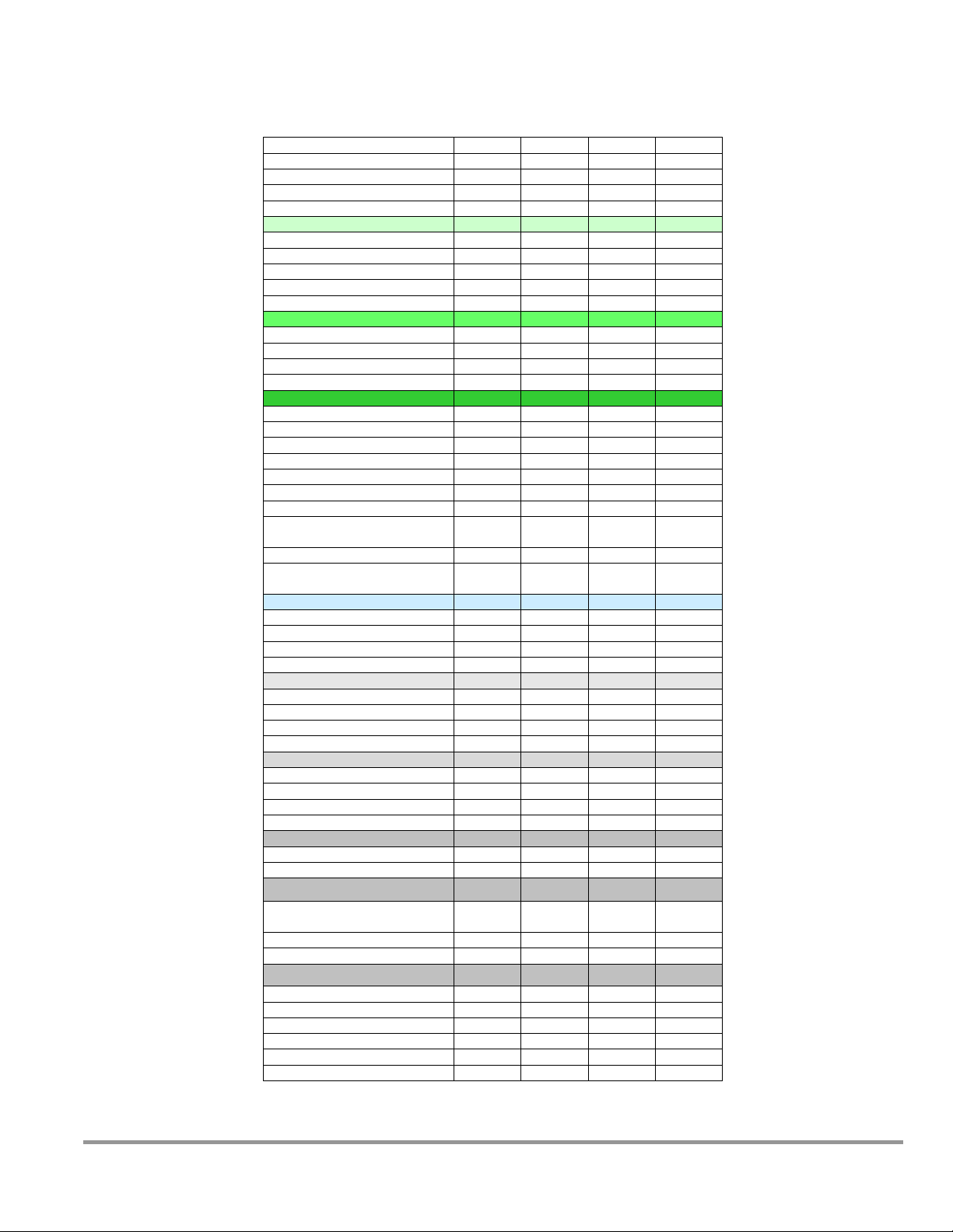
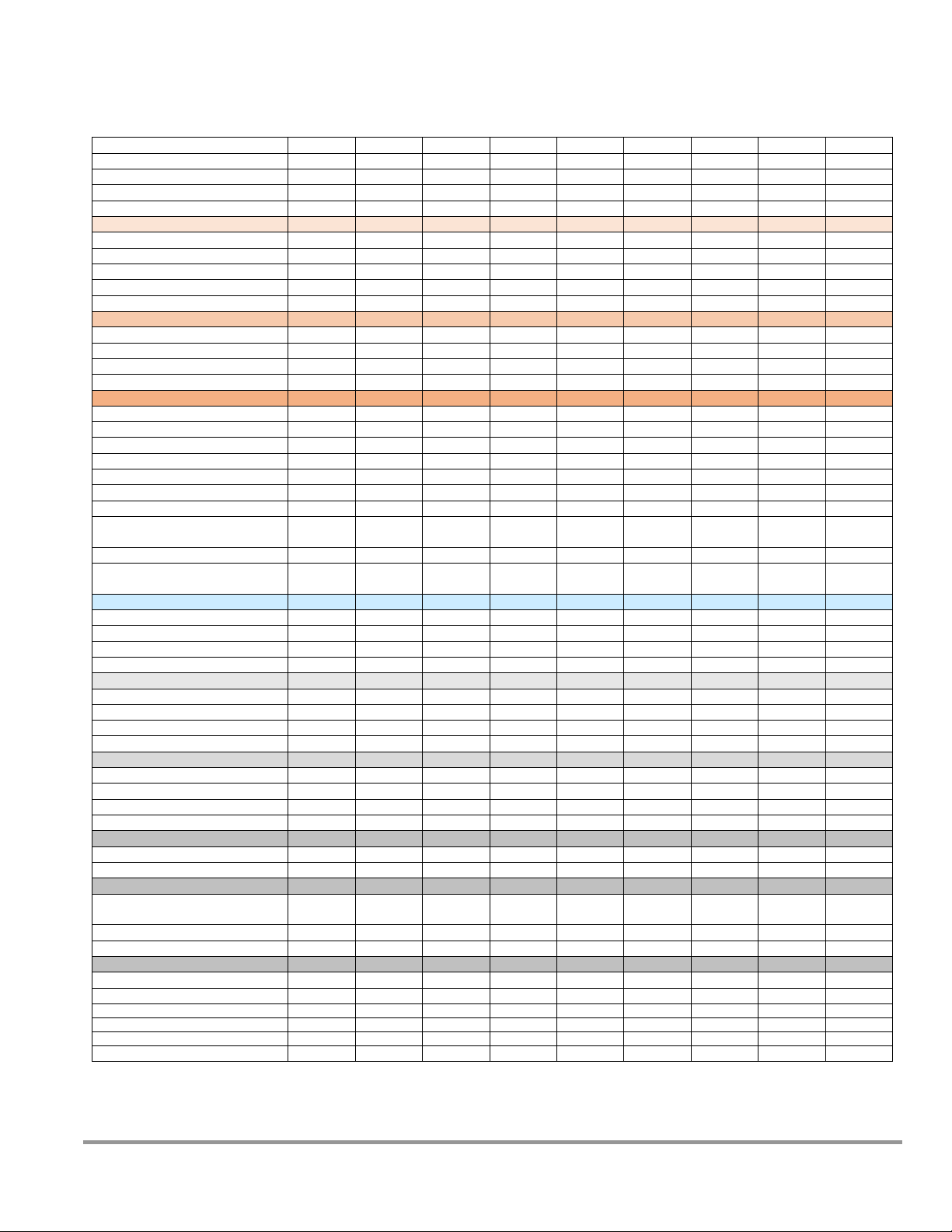
21
QuickChart – Logic+ Type A1 - Imperial Units
Model
30132
30142
30152
30162
Type
A1
A1
A1
A1
Cabinet Size (in feet)
3 4 5
6
Sash Opening (inches)
12
12
12
12
Starting Serial #
1303_
1303_
1303_
1303_
Downflow Data
Nominal Avg. Downflow (FPM)
55+/-5
55+/-5
55+/-5
55+/-5
grid # of points (rows x columns)
21 (3x7)
24 (3x8)
30(3x10)
36(3x12)
Grid distance from back & sides
6.0
6.0
6.0
6.0
Distance between rows
5.55
5.55
5.55
5.55
Distance between columns
4.08
5.21
5.39
5.50
Inflow Data
Nominal Average Inflow (FPM)
85+/-5
85+/-5
85+/-5
85+/-5
Sash Open Area (Sq. Ft)
3.04
4.04
5.04
6.04
Nominal Avg. Exhaust Vol. (CFM)
259
344
428
514
Avg. Exhaust Vol. Range (CFM)
243-274
323-364
403-454
483-544
Secondary Inflow Data
3
Sash Opening Template1
3+
4+
5+
6+
Sensor distance (inches)2
4
3.25
3.25 4 # of Test points
6 8 10
12
Test point location
* * *
*
Nominal Avg. Inflow Vel. (FPM)
259
344
428
281
Avg. Inflow Vel. Range (FPM)
243-274
323-364
403-454
264-297
Correction Factor (CF)
1 1 1
1.83
Average Inflow Volume Range
(AIV) (Avg. velocity x CF)
243-274
323-364
403-454
483-544
Sash Open Area (Sq. Ft)
3.04
4.04
5.04
6.04
Inflow Velocity Range
(AIV / Sash open area)
85+/-5
85+/-5
85+/-5
85+/-5
HEPA Filter Leak Test Data
Air Displacement (CFM)
600
800
1000
1200
Laskin Nozzles needed
1 2 2
2
Theoretical aerosol conc. (ug/l)3
23
34
27
23
Actual aerosol conc. (ug/l)4
12
18
15
15
Supply HEPA Data
Width x Depth x Height (in.)5
36x18x3.06
48x18x3.06
60x18x3.06
72x18x3.06
Performance (CFM)
335
445
555
665
Performance (Pressure in. H2O)
< .60”
<.45”
<.45”
<.42”
Labconco P/N
3838400
3838401
3838402
3838403
Exhaust HEPA Data
Width x Depth x Height (in.) 5
18x18x5.88
26x18x5.88
36x18x5.88
48x18x5.88
Performance (CFM)
266
353
441
529
Performance (Pressure in. H2O)
< 0.35”
< 0.28”
< 0.28”
< 0.28”
Labconco P/N
3838500
3838501
3838502
3838503
Motor/Blower Data
Labconco P/N6
3832200
3832201
3832207
3832208
Motor HP
½
½ ¾ ¾
Fluorescent Lamp Data
Fluorescent Lamps (2 each)
F25T8
TL741
F32T8
TL741
F40T8
SP41
F40T8
SP41
Fluor. Lamp Labconco Part #
9721901
9721900
9721903
9721903
Fluor. Ballast Labconco Part #
3838100
3838100
3838100
3838100
Ventus Canopy Data
Labconco Canopy P/N
3889200
3889201
3889202
3889203
Canopy Slot Area (F2)
.12
.12
.12
.12
Canopy Inflow Range (CFM)
20-100
20-100
20-100
20-100
Nominal Canopy Slot Velocity (FPM)
240-260
240-260
240-260
240-260
Nominal Canopy Slot Volume (CFM)
50
50
50
50
Canopy Vacuum (In. H2O)
0.1-0.15
0.1-0.15
0.1-0.15
0.1-0.15
Product Service 1-800-522-7658
Page 22
22
QuickChart – Logic+ Type A1 - Metric
Model
30132
30142
30152
30162
Type
A1
A1
A1
A1
Cabinet Size (in meters)
.91
1.22
1.52
1.83
Sash Opening (inches)
305
305
305
305
Starting Serial #
1303_
1303_
1303_
1303_
Downflow Data
Nominal Avg. Downflow (m/s)
.279 +/-.03
.279 +/-.03
.279 +/-.03
.279 +/-.03
grid # of points (rows x columns)
21 (3x7)
24 (3x8)
30(3x10)
36(3x12)
Grid distance from back & sides
152
152
152
152
Distance between rows (mm)
141
141
141
141
Distance between columns (mm)
104
132
137
140
Inflow Data
Nominal Average Inflow (m/s)
.432 +/-.03
.432 +/-.03
.432 +/-.03
.432 +/-.03
Sash Open Area (Sq. m)
.283
.375
.468
.561
Nominal Avg. Exhaust Vol. (m3/s)
.122
.162
.202
.242
Avg. Exhaust Vol. Range (m3/s)
.115-.129
.153-.172
.190-.214
.228-.257
Secondary Inflow Data
3
Sash Opening Template1
3+
4+
5+
6+
Sensor distance (mm)2
102
83
83
102
# of Test points
6 8 10
12
Test point location
* * *
*
Nominal Avg. Inflow Vel. (m/s)
1.32
1.75
2.17
1.43
Avg. Inflow Vel. Range (m/s)
1.23-1.39
1.64-1.85
2.05-2.31
1.34-1.51
Correction Factor (CF)
.0929
.0929
.0929
.1700
Average Inflow Volume Range
(AIV) (Avg. velocity x CF)
.115-.129
.153-.172
.190-.214
.228-.257
Sash Open Area (Sq. m)
.283
.375
.468
.561
Inflow Velocity Range
(AIV / Sash open area)
.432 +/-.03
.432 +/-.03
.432 +/-.03
.432 +/-.03
HEPA Filter Leak Test Data
Air Displacement (m/s)
.283
.378
.472
.566
Laskin Nozzles needed
1 2 2
2
Theoretical aerosol conc. (ug/l)3
23
34
27
23
Actual aerosol conc. (ug/l)4
12
18
15
15
Supply HEPA Data
Width x Depth x Height (in.)5
36x18x3.06
48x18x3.06
60x18x3.06
72x18x3.06
Performance (CFM)
335
445
555
665
Performance (Pressure in. H2O)
< .60”
<.45”
<.45”
<.42”
Labconco P/N
3838400
3838401
3838402
3838403
Exhaust HEPA Data
Width x Depth x Height (in.) 5
18x18x5.88
26x18x5.88
36x18x5.88
48x18x5.88
Performance (CFM)
266
353
441
529
Performance (Pressure in. H2O)
< 0.35”
< 0.28”
< 0.28”
< 0.28”
Labconco P/N
3838500
3838501
3838502
3838503
Motor/Blower Data
Labconco P/N6
3832200
3832201
3832207
3832208
Motor HP
½
½ ¾ ¾
Fluorescent Lamp Data
Fluorescent Lamps (2 each)
F25T8 TL741
F32T8 TL741
F40T8 SP41
F40T8 SP41
Fluor. Lamp Labconco Part #
9721901
9721900
9721903
9721903
Fluor. Ballast Labconco Part #
3838100
3838100
3838100
3838100
Ventus Canopy Data
Labconco Canopy P/N
3889200
3889201
3889202
3889203
Canopy Slot Area (m2)
.0111
.0111
.0111
.0111
Canopy Inflow Range (m/s)
.010-.047
.010-.047
.010-.047
.010-.047
Nominal Canopy Slot Velocity (m/s)
1.22-1.32
1.22-1.32
1.22-1.32
1.22-1.32
Nominal Canopy Slot Volume (m3/s)
.235
.235
.235
.235
Canopy Vacuum (Pa)
25-37
25-37
25-37
25-37
Product Service 1-800-522-7658
Page 23

23
QuickChart - Logic Type A1 BSCs footnotes
Logic Model Identification
The primary serial tag is on the lower outside edge of the right corner post.
The secondary serial tag is located on the front of the electronics module on
the top right side of the cabinet.
The first two digits of the serial number are the year of production; the next
two are the month. The next 5 digits are the sequence of production, and
the letter following the serial number is the revision level of the cabinet.
Downflow Test Specifications
All models are classified as uniform downflow.
All tests performed as described in ANSI/NSF Standard 49:2012.
UV Lamp, IV bar and all other accessories must be removed before
measuring downflow.
Inflow Test Specifications
All tests performed as described in ANSI/NSF Standard 49:2007.
Secondary Inflow Test Specifications
Must use Labconco holder P/N 3836405 to perform this test properly.
1. Use the appropriate template included in Certifier Kit# 3858403.
2. Measured from the bottom edge of the probe holder to the center of the
thermal anemometer sensor element.
* - Locate the single row of holes at the front of the grille. Mark the 6th hole
from the side wall and subsequent test points every 9 holes until the number of
test points marked equals the width of the cabinet in feet (3-foot cabinet, mark
the first 3 points). Repeat for the opposite side.
HEPA Filter Leak Test Specifications
3. Based on mineral oil.
4. The actual aerosol concentration is what was observed during testing.
Aerosol generator should be placed in the left rear corner of the work area, pointing
toward the rear grille. For uncontaminated units, the upstream concentration can be
sampled from the tube located under the work surface
Metric calculation of concentration is:
# of Laskin nozzles @ 138K Pascals x 6.372/Volume of air in m3/sec. = Conc. In ug/l
Supply and Exhaust HEPA Filter Specifications
5. Without gasket
Motor / Blower Specifications
6. Each motor must be programmed by Labconco for the appropriate width
cabinet. The speed control settings will fluctuate depending on local
temperature and pressure.
UV lamp Specifications
For all models, the UV lamp number is G30T8. The Labconco part number is
1271300.
For all 115/230 VAC models, the ballast assembly is Labconco part number
3829901.
For all 100 VAC models, the ballast assembly is Labconco part number
3830600.
Product Service 1-800-522-7658
Page 24
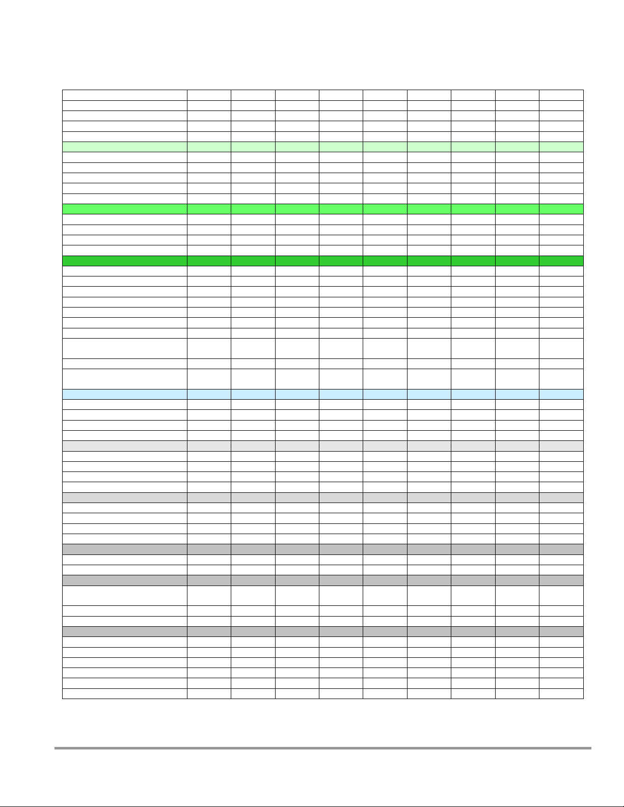
24
QuickChart – Logic+ Type A2 – Imperial Units
Model
30231
30238
30241
30248
30248xx80
30251
30258
30261
30268
Type
A2
A2
A2
A2
A2
A2
A2
A2
A2
Cabinet Size (in feet)
3 3 4 4 4 5 5 6 6
Sash Opening (inches)
10 8 10 8 8
10 8 10 8 Starting Serial #
1303_
1303_
1303_
1303_
1303_
1303_
1303_
1303_
1303_
Downflow Data
Nominal Avg. Downflow (FPM)
55+/-5
55+/-5
55+/-5
55+/-5
70+/-5
55+/-5
55+/-5
55+/-5
55+/-5
grid # of points (rows x columns)
21 (3x7)
21 (3x7)
24 (3x8)
24 (3x8)
24 (3x8)
30(3x10)
30(3x10)
36(3x12)
36(3x12)
Grid distance from back & sides
6.0
6.0
6.0
6.0
6.0
6.0
6.0
6.0
6.0
Distance between rows
5.55
5.75
5.55
5.75
5.75
5.55
5.75
5.55
5.75
Distance between columns
4.08
4.08
5.21
5.21
5.21
5.39
5.39
5.50
5.50
Inflow Data
Nominal Average Inflow (FPM)
105+/-5
105+/-5
105+/-5
105+/-5
105+/-5
105+/-5
105+/-5
105+/-5
105+/-5
Sash Open Area (Sq. Ft)
2.53
2.03
3.37
2.69
2.69
4.2
3.36
5.03
4.03
Nominal Avg. Exhaust Vol. (CFM)
266
213
354
283
283
441
353
529
423
Avg. Exhaust Vol. Range (CFM)
253-278
203-223
337-371
269-296
269-296
420-462
336-370
503-553
403-443
Secondary Inflow Data
3
Sash Opening Template
1
3+
3+
4+
4+
4+
5+
5+
6+
6+
Sensor distance (inches)2
4 4 3.25
3.25
3.25
3.25
3.25 4 4
# of Test points
6 6 8 8 8
10
10
12
12
Test point location
* * * * * * * * *
Nominal Avg. Inflow Vel. (FPM)
266
213
354
283
283
441
353
289
231
Avg. Inflow Vel. Range (FPM)
253-278
203-223
337-371
269-296
269-296
420-462
336-370
275-302
220-242
Correction Factor (CF)
1 1 1 1 1 1 1
1.83
1.83
Average Inflow Volume Range
(AIV) (Avg. velocity x CF)
253-278
203-223
337-371
269-296
269-296
420-462
336-370
503-553
403-443
Sash Open Area (Sq. Ft)
2.53
2.03
3.37
2.69
2.69
4.2
3.36
5.03
4.03
Inflow Velocity Range
(AIV / Sash open area)
100-110
100-110
100-110
100-110
100-110
100-110
100-110
100-110
100-110
HEPA Filter Leak Test Data
Air Displacement (CFM)
600
550
800
725
900
1000
900
1200
1100
Laskin Nozzles needed
1 1 2 2 2 2 2 2 2
Theoretical aerosol conc. (ug/l)3
23
25
34
37
30
27
30
23
25
Actual aerosol conc. (ug/l)4
12
14
18
21
17
15
17
15
17
Supply HEPA Data
Width x Depth x Height (in.)5
36x18x3.06
36x18x3.06
48x18x3.06
48x18x3.06
48x18x3.06
60x18x3.06
60x18x3.06
72x18x3.06
72x18x3.06
Performance (CFM)
335
335
445
445
445
555
555
665
665
Performance (Pressure in. H2O)
< .60”
<.60”
<.45”
<.45”
<.45”
< .45”
<.45”
<.42”
<.42”
Labconco P/N
3838400
3838400
3838401
3838401
3838401
3838402
3838402
3838403
3838403
Exhaust HEPA Data
Width x Depth x Height (in.) 5
18x18x5.88
18x18x5.88
26x18x5.88
26x18x5.88
26x18x5.88
36x18x5.88
36x18x5.88
48x18x5.88
48x18x5.88
Performance (CFM)
266
266
353
353
353
441
441
529
529
Performance (Pressure in. H2O)
< 0.35”
< 0.35”
< 0.28”
< 0.28”
< 0.28”
< 0.28”
< 0.28”
< 0.28”
< 0.28”
Labconco P/N
3838500
3838500
3838501
3838501
3838501
3838502
3838502
3838503
3838503
Motor/Blower Data
Labconco P/N6
3832200
3832200
3832201
3832201
3832201
3832207
3832207
3832208
3832208
Motor HP
½
½ ½ ½ ½ ¾ ¾ ¾
¾
Fluorescent Lamp Data
Fluorescent Lamps (2 each)
F25T8
TL741
F25T8
TL741
F32T8
TL741
F32T8
TL741
F32T8
TL741
F40T8
SP41
F40T8
SP41
F40T8
SP41
F40T8
SP41
Fluor. Lamp Labconco Part #
9721901
9721901
9721900
9721900
9721900
9721903
9721903
9721903
9721903
Fluor. Ballast Labconco Part #
3838100
3838100
3838100
3838100
3838100
3838100
3838100
3838100
3838100
Ventus Canopy Data
Labconco Canopy P/N
3889200
3889200
3889201
3889201
3889201
3889202
3889202
3889203
3889203
Canopy Slot Area (F2)
.12
.12
.12
.12
.12
.12
.12
.12
.12
Canopy Inflow Range (CFM)
20-100
20-100
20-100
20-100
20-100
20-100
20-100
20-100
20-100
Nominal Canopy Slot Velocity (FPM)
240-260
240-260
240-260
240-260
240-260
240-260
240-260
240-260
240-260
Nominal Canopy Slot Volume (CFM)
50
50
50
50
50
50
50
50
50
Canopy Vacuum (In. H2O)
0.1-0.15
0.1-0.15
0.1-0.15
0.1-0.15
0.1-0.15
0.1-0.15
0.1-0.15
0.1-0.15
0.1-0.15
Product Service 1-800-522-7658
Page 25
25
QuickChart – Logic+ Type A2 – Metric Units
Model
30231
30238
30241
30248
30248xx80
30251
30258
30261
30268
Type
A2
A2
A2
A2
A2
A2
A2
A2
A2
Cabinet Size (in m)
.91
.91
1.22
1.22
1.22
1.52
1.52
1.83
1.83
Sash Opening (mm)
254
203
254
203
203
254
203
254
203
Starting Serial #
1303_
1303_
1303_
1303_
1303_
1303_
1303_
1303_
1303_
Downflow Data
Nominal Avg. Downflow (m/s)
.279+/.03
.279+/.03
.279+/.03
.279+/.03
.356+/.03
.279+/.03
.279+/.03
.279+/.03
.279+/.03
grid # of points (rows x columns)
21 (3x7)
21 (3x7)
24 (3x8)
24 (3x8)
24 (3x8)
30(3x10)
30(3x10)
36(3x12)
36(3x12)
Grid distance from back & sides (mm)
152
152
152
152
152
152
152
152
152
Distance between rows (mm)
141
146
141
146
146
141
146
141
146
Distance between columns (mm)
104
104
132
132
132
137
137
140
140
Inflow Data
Nominal Average Inflow (m/s)
.533+/-.03
.533+/-.03
.533+/-.03
.533+/-.03
.533+/-.03
.533+/-.03
.533+/-.03
.533+/-.03
.533+/-.03
Sash Open Area (Sq. m)
.235
.188
.313
.250
.250
.390
.312
.468
.374
Nominal Avg. Exhaust Vol. (m3/s)
.126
.100
.167
.134
.134
.208
.166
.249
.200
Avg. Exhaust Vol. Range (m3/s)
.120-.132
.096-.105
.159-.175
.127-.140
.127-.140
.198-.218
.159-.174
.238-.261
.190-.209
Secondary Inflow Data
3
Sash Opening Template
1
3+
3+
4+
4+
4+
5+
5+
6+
6+
Sensor distance (mm)2
102
102
83
83
83
83
83
102
102
# of Test points
6 6 8 8 8
10
10
12
12
Test point location
* * * * * * * * *
Nominal Avg. Inflow Vel. (m/s)
1.35
1.08
1.80
1.44
1.44
2.24
1.79
1.47
1.17
Avg. Inflow Vel. Range (m/s)
1.29-1.41
1.03-1.13
1.71-1.88
1.37-1.50
1.37-1.50
2.13-2.35
1.71-1.88
1.40-1.53
1.12-1.23
Correction Factor (CF)
.0929
.0929
.0929
.0929
.0929
.0929
.0929
.1700
.1700
Average Inflow Volume Range
(AIV) (Avg. velocity x CF)
.120-.132
.096-.105
.159-.175
.127-.140
.127-.140
.198-.218
.159-.174
.238-.261
.190-.209
Sash Open Area (Sq. m)
.235
.188
.313
.250
.250
.390
.312
.468
.374
Inflow Velocity Range
(AIV / Sash open area)
.533+/-.03
.533+/-.03
.533+/-.03
.533+/-.03
.533+/-.03
.533+/-.03
.533+/-.03
.533+/-.03
.533+/-.03
HEPA Filter Leak Test Data
Air Displacement (m3/s)
.283
.260
.378
.342
.425
.472
.425
.566
.519
Laskin Nozzles needed
1 1 2 2 2 2 2 2 2
Theoretical aerosol conc. (ug/l)3
23
25
34
38
30
27
30
23
25
Actual aerosol conc. (ug/l)4
12
14
18
21
17
15
17
15
17
Supply HEPA Data
Width x Depth x Height (in.)5
36x18x3.06
36x18x3.06
48x18x3.06
48x18x3.06
48x18x3.06
60x18x3.06
60x18x3.06
72x18x3.06
72x18x3.06
Performance (CFM)
335
335
445
445
445
555
555
665
665
Performance (Pressure in. H2O)
< .60”
<.60”
<.45”
<.45”
<.45”
< .45”
<.45”
<.42”
<.42”
Labconco P/N
3838400
3838400
3838401
3838401
3838401
3838402
3838402
3838403
3838403
Exhaust HEPA Data
Width x Depth x Height (in.) 5
18x18x5.88
18x18x5.88
26x18x5.88
26x18x5.88
26x18x5.88
36x18x5.88
36x18x5.88
48x18x5.88
48x18x5.88
Performance (CFM)
266
266
353
353
353
441
441
529
529
Performance (Pressure in. H2O)
< 0.35”
< 0.35”
< 0.28”
< 0.28”
< 0.28”
< 0.28”
< 0.28”
< 0.28”
< 0.28”
Labconco P/N
3838500
3838500
3838501
3838501
3838501
3838502
3838502
3838503
3838503
Motor/Blower Data
Labconco P/N6
3832200
3832200
3832201
3832201
3832201
3832207
3832207
3832208
3832208
Motor HP
½
½ ½ ½ ½ ¾ ¾ ¾
¾
Fluorescent Lamp Data
Fluorescent Lamps (2 each)
F25T8
TL741
F25T8
TL741
F32T8
TL741
F32T8
TL741
F32T8
TL741
F40T8
SP41
F40T8
SP41
F40T8
SP41
F40T8
SP41
Fluor. Lamp Labconco Part #
9721901
9721901
9721900
9721900
9721900
9721903
9721903
9721903
9721903
Fluor. Ballast Labconco Part #
3838100
3838100
3838100
3838100
3838100
3838100
3838100
3838100
3838100
Ventus Canopy Data
Labconco Canopy P/N
3889200
3889200
3889201
3889201
3889201
3889202
3889202
3889203
3889203
Canopy Slot Area (m2)
.0111
.0111
.0111
.0111
.0111
.0111
.0111
.0111
.0111
Canopy Inflow Range (m/s)
.010-.047
.010-.047
.010-.047
.010-.047
.010-.047
.010-.047
.010-.047
.010-.047
.010-.047
Nominal Canopy Slot Velocity (m/s)
1.22-1.32
1.22-1.32
1.22-1.32
1.22-1.32
1.22-1.32
1.22-1.32
1.22-1.32
1.22-1.32
1.22-1.32
Nominal Canopy Slot Volume (m3/s)
.235
.235
.235
.235
.235
.235
.235
.235
.235
Canopy Vacuum (Pa)
25-37
25-37
25-37
25-37
25-37
25-37
25-37
25-37
25-37
Product Service 1-800-522-7658
Page 26

26
QuickChart - Logic Type A2 BSCs footnotes
Logic Model Identification
The primary serial tag is on the lower outside edge of the right corner post.
The secondary serial tag is located on the front of the electronics module on
the top right side of the cabinet.
The first two digits of the serial number are the year of production; the next
two are the month. The next 5 digits are the sequence of production, and
the letter following the serial number is the revision level of the cabinet.
Downflow Test Specifications
All models are classified as uniform downflow.
All tests performed as described in ANSI/NSF Standard 49:2012.
UV Lamp, IV bar and all other accessories must be removed before
measuring downflow.
Inflow Test Specifications
All tests performed as described in ANSI/NSF Standard 49:2012.
Secondary Inflow Test Specifications
Must use Labconco holder P/N 3836405 to perform this test properly.
1. Use the appropriate template included in Certifier Kit# 3858403.
2. Measured from the bottom edge of the probe holder to the center of the
thermal anemometer sensor element.
* - Locate the single row of holes at the front of the grille. Mark the 6th hole
from the side wall and subsequent test points every 9 holes until the number of
test points marked equals the width of the cabinet in feet (3-foot cabinet, mark
the first 3 points). Repeat for the opposite side.
HEPA Filter Leak Test Specifications
3. Based on mineral oil.
4. The actual aerosol concentration is what was observed during testing.
Aerosol generator should be placed in the left rear corner of the work area, pointing
toward the rear grille. For uncontaminated units, the upstream concentration can be
sampled from the tube located under the work surface
Metric calculation of concentration is:
# of Laskin nozzles @ 138K Pascals x 6.372/Volume of air in m3/sec. = Conc. In ug/l
Supply and Exhaust HEPA Filter Specifications
5. Without gasket
Motor / Blower Specifications
6. Each motor must be programmed by Labconco for the appropriate width
cabinet. The speed control settings will fluctuate depending on local
temperature and pressure.
UV lamp Specifications
For all models, the UV lamp number is G30T8. The Labconco part number is
1271300.
For all 115/230 VAC models, the ballast assembly is Labconco part number
3829901.
For all 100 VAC models, the ballast assembly is Labconco part number
3830600.
Product Service 1-800-522-7658
Page 27
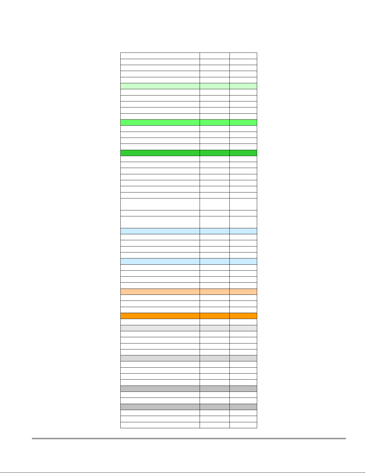
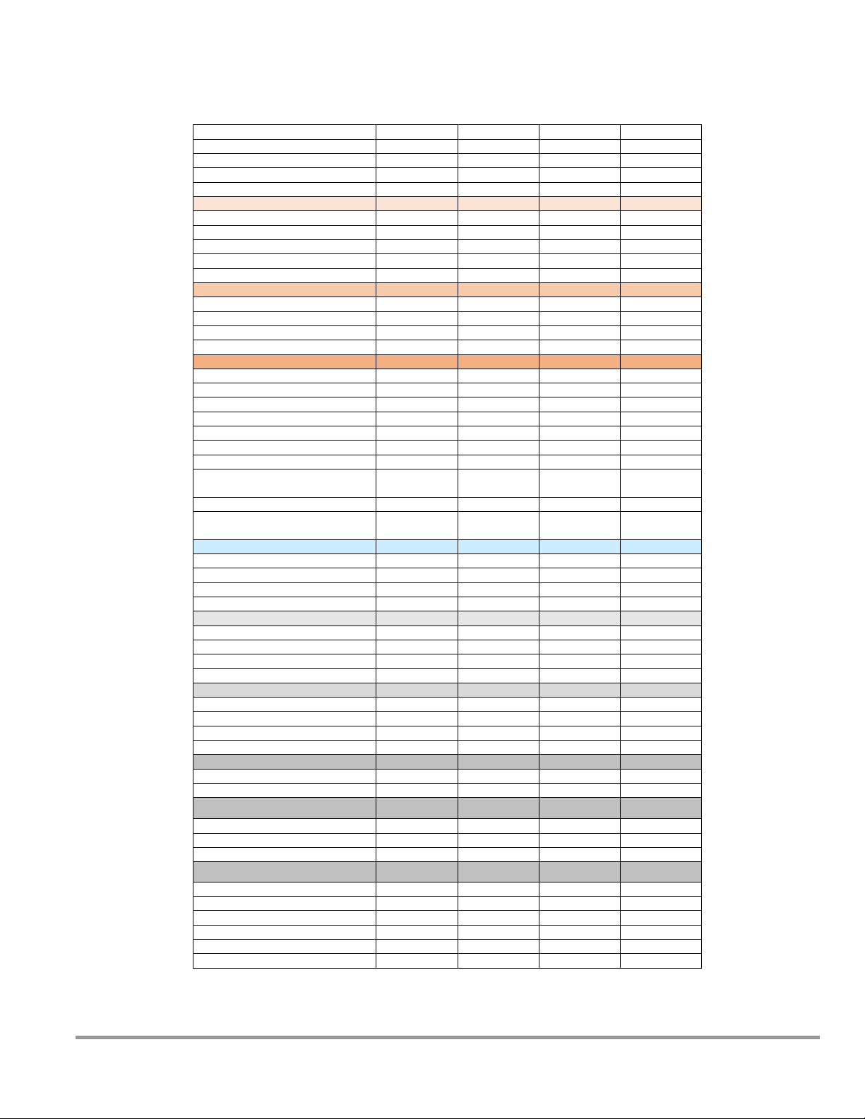
27
QuickChart – Logic+ Type B2 Imperial Units
Model
30348
30368
Type
B2
B2
Cabinet Size (in feet)
4
6
Sash Opening (inches)
8 8 Starting Serial #
1303_
1303_
Downflow Data
Nominal Avg. Downflow (FPM)
55+/-5
55+/-5
grid # of points (rows x columns)
24 (3x8)
36(3x12)
Grid distance from back & sides
6.0
6.0
Distance between rows
5.75
5.75
Distance between columns
5.21
5.50
Inflow Data
Nominal Average Inflow (FPM)
105+/-5
105+/-5
Sash Open Area (Sq. Ft)
2.69
4.03
Nominal Avg. Exhaust Vol. (CFM)
283
423
Avg. Exhaust Vol. Range (CFM)
269-296
403-443
Secondary Inflow Data
3
Sash Opening Template
1
3.7
4.95
Sensor distance (inches)2
3.25 4 # of Test points
8
12
Test point location
*
*
Nominal Avg. Inflow Vel. (FPM)
283
231
Avg. Inflow Vel. Range (FPM)
269-296
220-242
Correction Factor (CF)
1
1.83
Average Inflow Volume Range
(AIV) (Avg. velocity x CF)
269-296
403-443
Sash Open Area (Sq. Ft)
2.69
4.03
Inflow Velocity Range
(AIV / Sash open area)
100-110
100-110
Supply HEPA Leak Test Data
Air Displacement (CFM)
445
665
Laskin Nozzles needed
1 1 Theoretical aerosol conc. (ug/l)3
30
20
Actual aerosol conc. (ug/l)4
15
12
Exhaust HEPA Leak Test Data
Air Displacement (CFM)
665
998
Laskin Nozzles needed
2
2
Theoretical aerosol conc. (ug/l)3
41
27
Actual aerosol conc. (ug/l)4
25
19
Exhaust Data
DIM Exhaust Volume (CFM)5
665
998
Traverse Exhaust Volume (CFM)6
810
1218
Differential Pressure (in. H20)7
1.5
1.8
Exhaust (Inflow) Alarm Data
Alarm Setpoint (CFM Inflow)
150 +/- 5
223 +/- 5
Supply HEPA Data
Width x Depth x Height (in.)8
48x18x3.06
72x18x3.06
Performance (CFM)
445
665
Performance (Pressure in. H2O)
<.45
<.42
Labconco P/N
3838401
3838403
Exhaust HEPA Data
Width x Depth x Height (in.) 8
26x18x8.08
48x18x8.08
Performance (CFM)
720
1100
Performance (Pressure in. H2O)
.48+/-.07
.37+/-.07
Labconco P/N
3438501
3438503
Motor/Blower Data
Labconco P/N6
3832209
3832210
Motor HP
½
½
Fluorescent Lamp Data
Fluorescent Lamps (2 each)
F32T8 TL741
F40T8 SP41
Fluor. Lamp Labconco Part #
9721900
9721903
Fluor. Ballast Labconco Part #
3838100
3838100
Product Service 1-800-522-7658
Page 28
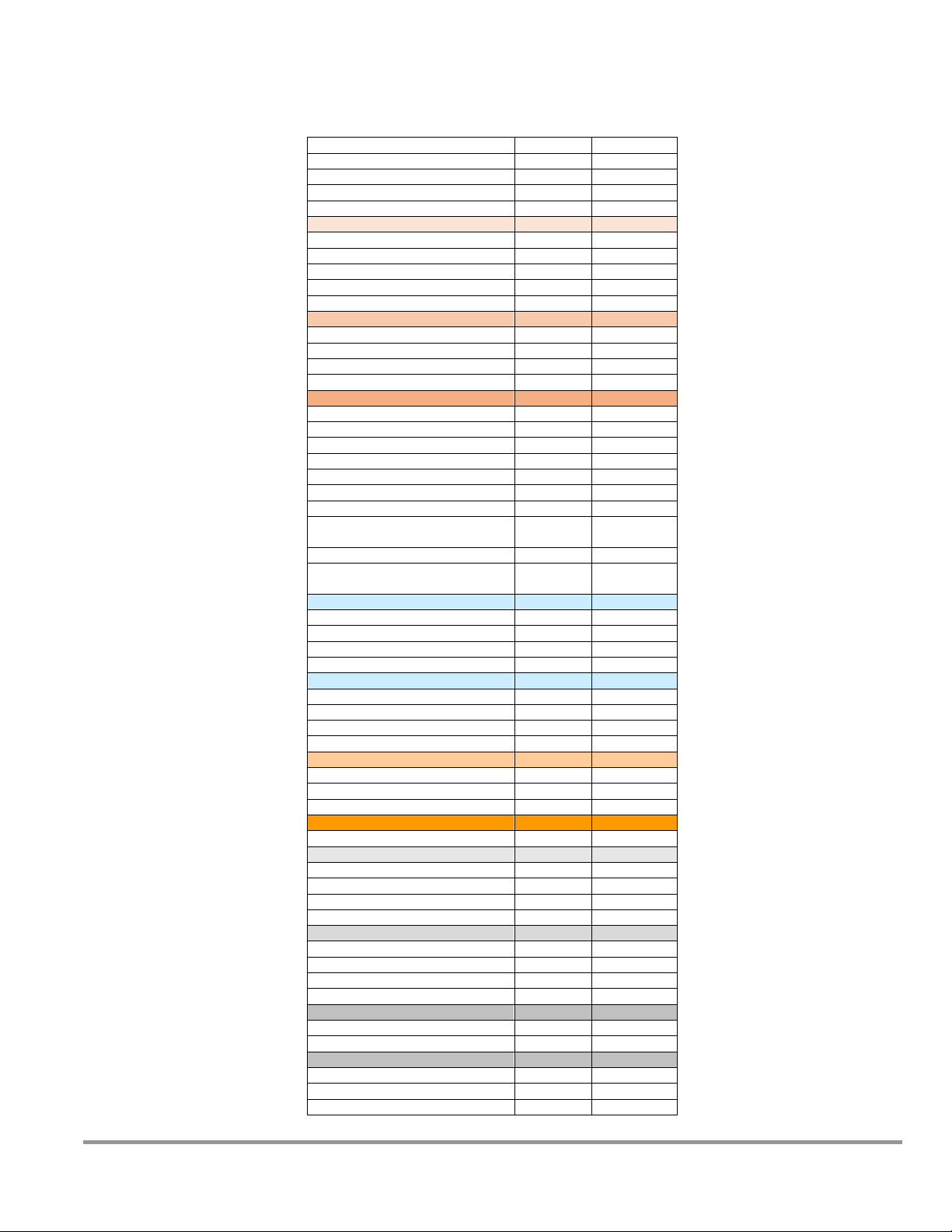
28
QuickChart – Logic+ Type B2 Metric Units
Model
30348
30368
Type
B2
B2
Cabinet Size (in m)
1.22
6
Sash Opening (mm)
203 8 Starting Serial #
1303_
1303_
Downflow Data
Nominal Avg. Downflow (m/s)
.279+/.03
55+/-5
grid # of points (rows x columns)
24 (3x8)
36(3x12)
Grid distance from back & sides
152
6.0
Distance between rows (mm)
146
5.75
Distance between columns (mm)
132
5.50
Inflow Data
Nominal Average Inflow (m/s)
.533+/-.03
105+/-5
Sash Open Area (Sq. m)
.250
.374
Nominal Avg. Exhaust Vol. (m3/s)
.134
.200
Avg. Exhaust Vol. Range (m3/s)
.127-.140
.190-.209
Secondary Inflow Data
3
Sash Opening Template
1
4+
6+
Sensor distance (mm)2
83
4
# of Test points
8
12
Test point location
*
*
Nominal Avg. Inflow Vel. (m/s)
1.44
1.17
Avg. Inflow Vel. Range (m/s)
1.37-1.50
1.12-1.23
Correction Factor (CF)
.0929
.1700
Average Inflow Volume Range
(AIV) (Avg. velocity x CF)
.127-.140
.190-.209
Sash Open Area (Sq. m)
.250
.374
Inflow Velocity Range
(AIV / Sash open area)
.533+/-.03
.533+/-.03
Supply HEPA Leak Test Data
Air Displacement (m3/s)
.210
.471
Laskin Nozzles needed
1 1 Theoretical aerosol conc. (ug/l)3
30
20
Actual aerosol conc. (ug/l)4
15
12
Exhaust HEPA Leak Test Data
Air Displacement (m3/s)
.314
.471
Laskin Nozzles needed
2
2
Theoretical aerosol conc. (ug/l)3
41
27
Actual aerosol conc. (ug/l)4
25
19
Exhaust Data
DIM Exhaust Volume (m3/s)5
.314
.471
Traverse Exhaust Volume (m3/s)6
.382
.575
Differential Pressure (Pa)7
374
448
Exhaust (Inflow) Alarm Data
Alarm Setpoint (m3/s Inflow)
.071 +/- .03
.105 +/-.03
Supply HEPA Data
Width x Depth x Height (in.)8
48x18x3.06
72x18x3.06
Performance (CFM)
445
665
Performance (Pressure in. H2O)
<.45
<.42
Labconco P/N
3838401
3838403
Exhaust HEPA Data
Width x Depth x Height (in.) 8
26x18x8.08
48x18x8.08
Performance (CFM)
720
1100
Performance (Pressure in. H2O)
.48+/-.07
.37+/-.07
Labconco P/N
3438501
3438503
Motor/Blower Data
Labconco P/N6
3832209
3832210
Motor HP
½
½
Fluorescent Lamp Data
Fluorescent Lamps (2 each)
F32T8 TL741
F40T8 SP41
Fluor. Lamp Labconco Part #
9721900
9721903
Fluor. Ballast Labconco Part #
3838100
3838100
Product Service 1-800-522-7658
Page 29

29
QuickChart – Logic+/Cell Logic+ Type B2 BSCs
footnotes
Logic Model Identification
The primary serial tag is on the lower outside edge of the right corner post.
The secondary serial tag is located on the front of the electronics module on the top
right side of the cabinet.
The first two digits of the serial number are the year of production; the next two are
the month. The next 5 digits are the sequence of production, and the letter following
the serial number is the revision level of the cabinet.
Downflow Test Specifications
All models are classified as uniform downflow.
All tests performed as described in ANSI/NSF Standard 49:2012.
UV Lamp, IV bar and all other accessories must be removed before measuring
downflow.
Inflow Test Specifications
All tests performed as described in ANSI/NSF Standard 49:2012.
Secondary Inflow Test Specifications
Must use Labconco holder P/N 3836405 to perform this test properly.
1. Use the appropriate template included in Certifier Kit# 3858403.
2. Measured from the bottom edge of the probe holder to the center of the thermal
anemometer sensor element.
* - Locate the single row of holes at the front of the grille. Mark the 6th hole from the
side wall and subsequent test points every 9 holes until the number of test points
marked equals the width of the cabinet in feet (3-foot cabinet, mark the first 3 points).
Repeat for the opposite side.
HEPA Filter Leak Test Specifications
3. Based on mineral oil.
4. The actual aerosol concentration is what was observed during testing.
Aerosol generator should be placed in the left rear corner of the work area, pointing
toward the rear grille.
For uncontaminated units, the upstream concentration can be sampled from the
tube located under the work surface.
Metric calculation of concentration is:
# of Laskin nozzles @ 138K Pascals x 6.372/Volume of air in m3/sec. =
Conc. In ug/l
Exhaust Data
5. Total Exhaust Volume. Cabinet air intake sealed shut and cabinet blower off.
6. Measured as per ASHRAE methodology for measuring air volume in round ducts.
7. Measured at the exhaust transition sampling point, relative to atmosphere.
Supply and Exhaust HEPA Filter Specifications
8. Without gasket
Motor / Blower Specifications
9. Each motor must be programmed by Labconco for the appropriate width cabinet.
UV lamp Specifications
For all models, the UV lamp number is G30T8. The Labconco part number is
For all 115/230 VAC models, the ballast assembly is Labconco part number 3829901.
For all 100 VAC models, the ballast assembly is Labconco part number 3830600. The
The speed control settings will fluctuate depending on local temperature and
pressure.
1271300.
The ballast is Robertson part number PSM2GPH18MVW.
ballast is Robertson part number RSO1GPH30100.
Product Service 1-800-522-7658
Page 30
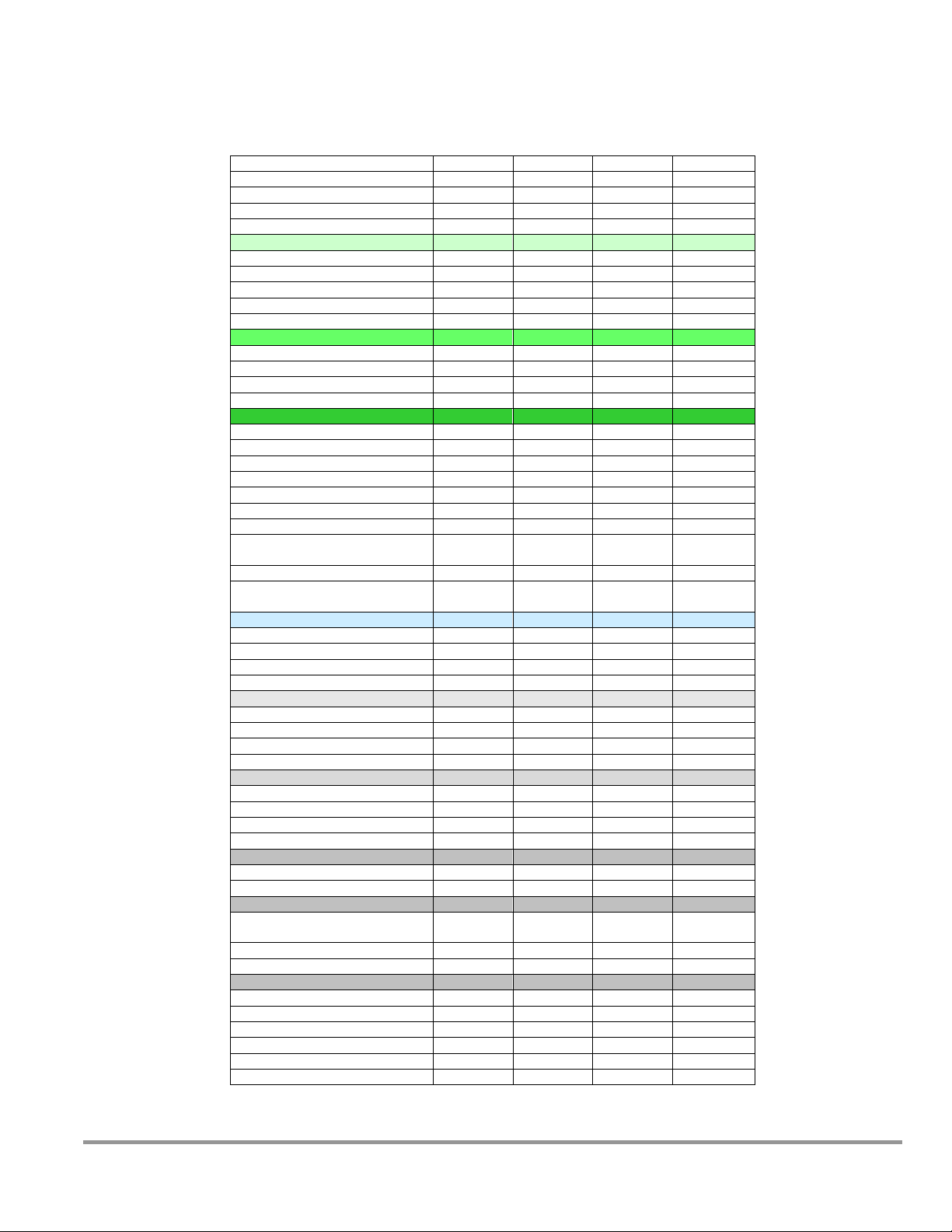
30
QuickChart – Logic+ PuriCare Procedure Stations
Model
31241
31142
31261
31162
Type
A2
A1
A2
A1
Cabinet Size (in feet)
4 4 6 6 Sash Opening (inches)
10
12
10
12
Starting Serial #
1303_
1303_
1303_
1303_
Downflow Data
Nominal Avg. Downflow (FPM)
55+/-5
55+/-5
55+/-5
55+/-5
grid # of points (rows x columns)
24 (3x8)
24 (3x8)
36(3x12)
36(3x12)
Grid distance from back & sides
6.0
6.0
6.0
6.0
Distance between rows
5.55
5.55
5.55
5.55
Distance between columns
5.21
5.21
5.50
5.50
Inflow Data
Nominal Average Inflow (FPM)
105+/-5
85+/-5
105+/-5
85+/-5
Sash Open Area (Sq. Ft)
3.37
4.04
5.03
6.04
Nominal Avg. Exhaust Vol. (CFM)
354
344
529
514
Avg. Exhaust Vol. Range (CFM)
337-371
323-364
503-553
483-544
Secondary Inflow Data
3
Sash Opening Template
1
3.81
3.81
4.95
4.95
Sensor distance (inches)2
3.25
3.25 4 4
# of Test points
8 8 12
12
Test point location
* * *
*
Nominal Avg. Inflow Vel. (FPM)
354
344
289
281
Avg. Inflow Vel. Range (FPM)
337-371
323-364
275-302
264-297
Correction Factor (CF)
1 1 1.83
1.83
Average Inflow Volume Range
(AIV) (Avg. velocity x CF)
337-371
323-364
503-553
483-544
Sash Open Area (Sq. Ft)
3.37
4.04
5.03
6.04
Inflow Velocity Range
(AIV / Sash open area)
100-110
85+/-5
100-110
85+/-5
HEPA Filter Leak Test Data
Air Displacement (CFM)
794
794
1189
1189
Laskin Nozzles needed
2 2 2
2
Theoretical aerosol conc. (ug/l)3
34
34
23
23
Actual aerosol conc. (ug/l)4
18
18
15
15
Supply HEPA Data
Width x Depth x Height (in.)5
48x18x3.06
48x18x3.06
72x18x3.06
72x18x3.06
Performance (CFM)
445
445
665
665
Performance (Pressure in. H2O)
<.45
<.45
<.42
<.42
Labconco P/N
3838401
3838401
3838403
3838403
Exhaust HEPA Data
Width x Depth x Height (in.) 5
26x18x5.88
26x18x5.88
48x18x5.88
48x18x5.88
Performance (CFM)
353
353
529
529
Performance (Pressure in. H2O)
< 0.28”
< 0.28”
< 0.28”
< 0.28”
Labconco P/N
3838501
3838501
3838503
3838503
Motor/Blower Data
Labconco P/N6
3832201
3832201
3832208
3832208
Motor HP
½ ½ ¾
¾
Fluorescent Lamp Data
Fluorescent Lamps (2 each)
F32T8
TL741
F32T8
TL741
F40T8
SP41
F40T8
SP41
Fluor. Lamp Labconco Part #
9721900
9721900
9721903
9721903
Fluor. Ballast Labconco Part #
3838100
3838100
3838100
3838100
Ventus Canopy Data
Labconco Canopy P/N
3889201
3889201
3889203
3889203
Canopy Slot Area (F2)
.12
.12
.12
.12
Canopy Inflow Range (CFM)
20-100
20-100
20-100
20-100
Nominal Canopy Slot Velocity (FPM)
240-260
240-260
240-260
240-260
Nominal Canopy Slot Volume (CFM)
50
50
50
50
Canopy Vacuum (In. H2O)
0.1-0.15
0.1-0.15
0.1-0.15
0.1-0.15
Imperial Units
Product Service 1-800-522-7658
Page 31

31
QuickChart – Logic+ PuriCare Procedure Stations
Model
31241
31142
31261
31162
Type
A2
A1
A2
A1
Cabinet Size (in m)
1.22
1.22
1.83
1.83
Sash Opening (mm)
254
305
254
305
Starting Serial #
1303_
1303_
1303_
1303_
Downflow Data
Nominal Avg. Downflow (m/s)
.279+/.03
.279 +/-.03
.279+/.03
.279 +/-.03
grid # of points (rows x columns)
24 (3x8)
24 (3x8)
36(3x12)
36(3x12)
Grid distance from back & sides (mm)
152
152
152
152
Distance between rows (mm)
141
141
141
141
Distance between columns (mm)
132
132
140
140
Inflow Data
Nominal Average Inflow (m/s)
.533+/-.03
.432 +/-.03
.533+/-.03
.432 +/-.03
Sash Open Area (Sq. m)
.313
.375
.468
.561
Nominal Avg. Exhaust Vol. (m3/s)
.167
.162
.249
.242
Avg. Exhaust Vol. Range (m3/s)
.159-.175
.153-.172
.238-.261
.228-.257
Secondary Inflow Data
3
Sash Opening Template
1
4+
4+
6+
6+
Sensor distance (mm)2
83
83
102
102
# of Test points
8 8 12
12
Test point location
* * *
*
Nominal Avg. Inflow Vel. (m/s)
1.80
1.75
1.47
1.43
Avg. Inflow Vel. Range (m/s)
1.71-1.88
1.64-1.85
1.40-1.53
1.34-1.51
Correction Factor (CF)
.0929
.0929
.1700
.1700
Average Inflow Volume Range
(AIV) (Avg. velocity x CF)
.159-.175
.153-.172
.238-.261
.228-.257
Sash Open Area (Sq. m)
.313
.375
.468
.561
Inflow Velocity Range
(AIV / Sash open area)
.533+/-.03
.432 +/-
.03
.533+/-.03
.432 +/-.03
HEPA Filter Leak Test Data
Air Displacement (m3/s)
.378
.378
.566
.566
Laskin Nozzles needed
2 2 2
2
Theoretical aerosol conc. (ug/l)3
34
34
23
23
Actual aerosol conc. (ug/l)4
18
18
15
15
Supply HEPA Data
Width x Depth x Height (in.)5
48x18x3.06
48x18x3.06
72x18x3.06
72x18x3.06
Performance (CFM)
445
445
665
665
Performance (Pressure in. H2O)
<.45”
<.45”
<.42”
<.42”
Labconco P/N
3838401
3838401
3838403
3838403
Exhaust HEPA Data
Width x Depth x Height (in.) 5
26x18x5.88
26x18x5.88
48x18x5.88
48x18x5.88
Performance (CFM)
353
353
529
529
Performance (Pressure in. H2O)
< 0.28”
< 0.28”
< 0.28”
< 0.28”
Labconco P/N
3838501
3838501
3838503
3838503
Motor/Blower Data
Labconco P/N6
3832201
3832201
3832208
3832208
Motor HP
½ ½ ¾
¾
Fluorescent Lamp Data
Fluorescent Lamps (2 each)
F32T8
TL741
F32T8
TL741
F40T8
SP41
F40T8
SP41
Fluor. Lamp Labconco Part #
9721900
9721900
9721903
9721903
Fluor. Ballast Labconco Part #
3838100
3838100
3838100
3838100
Ventus Canopy Data
Labconco Canopy P/N
3889201
3889201
3889203
3889203
Canopy Slot Area (m2)
.0111
.0111
.0111
.0111
Canopy Inflow Range (m/s)
.010-.047
.010-.047
.010-.047
.010-.047
Nominal Canopy Slot Velocity (m/s)
1.22-1.32
1.22-1.32
1.22-1.32
1.22-1.32
Nominal Canopy Slot Volume (m3/s)
.235
.235
.235
.235
Canopy Vacuum (Pa)
25-37
25-37
25-37
25-37
Metric Units
Product Service 1-800-522-7658
Page 32

32
QuickChart-Logic+ PuriCare Procedure
Stations footnotes
Logic Model Identification
The primary serial tag is on the lower outside edge of the right corner post.
The secondary serial tag is located on the front of the electronics module on
the top right side of the cabinet.
The first two digits of the serial number are the year of production; the next
two are the month. The next 5 digits are the sequence of production, and
the letter following the serial number is the revision level of the cabinet.
Downflow Test Specifications
All models are classified as uniform downflow.
All tests performed as described in ANSI/NSF Standard 49:2012.
UV Lamp, IV bar and all other accessories must be removed before
measuring downflow.
Inflow Test Specifications
All tests performed as described in ANSI/NSF Standard 49:2012.
Secondary Inflow Test Specifications
Must use Labconco holder P/N 3836405 to perform this test properly.
1. Use the appropriate template included in Certifier Kit# 3858403.
2. Measured from the bottom edge of the probe holder to the center of the
thermal anemometer sensor element.
* - Locate the single row of holes at the front of the grille. Mark the 6th hole
from the side wall and subsequent test points every 9 holes until the number of
test points marked equals the width of the cabinet in feet (3-foot cabinet, mark
the first 3 points). Repeat for the opposite side.
HEPA Filter Leak Test Specifications
3. Based on mineral oil.
4. The actual aerosol concentration is what was observed during testing.
Aerosol generator should be placed in the left rear corner of the work area, pointing
toward the rear grille. For uncontaminated units, the upstream concentration can be
sampled from the tube located under the work surface
Metric calculation of concentration is:
# of Laskin nozzles @ 138K Pascals x 6.372/Volume of air in m3/sec. =
Conc. In ug/l
Supply and Exhaust HEPA Filter Specifications
5. Without gasket
Motor / Blower Specifications
6. Each motor must be programmed by Labconco for the appropriate width
cabinet. The speed control settings will fluctuate depending on local
temperature and pressure.
UV lamp Specifications
For all models, the UV lamp number is G30T8. The Labconco part number is
1271300.
For all 115/230 VAC models, the ballast assembly is Labconco part number
3829901.
For all 100 VAC models, the ballast assembly is Labconco part number
3830600.
Product Service 1-800-522-7658
Page 33

33
QuickChart – Cell Logic+ Type A2 BSCs
Model
32239
33239
34239
32249
33249
34249
32259
33259
34259
32269
33269
34269
Type
A2
A2
A2
A2
Cabinet Size (in feet)
3 4 5
6
Sash Opening (inches)
9
9 9 9
Starting Serial #
1303_
1303_
1303_
1303_
Downflow Data
Nominal Avg. Downflow (FPM)
55+/-5
55+/-5
55+/-5
55+/-5
grid # of points (rows x columns)
21 (3x7)
24 (3x8)
30(3x10)
36(3x12)
Grid distance from back & sides
6.0
6.0
6.0
6.0
Distance between rows
5.55
5.55
5.55
5.55
Distance between columns
4.08
5.21
5.39
5.50
Inflow Data
Nominal Average Inflow (FPM)
105+/-5
105+/-5
105+/-5
105+/-5
Sash Open Area (Sq. Ft)
2.28
3.03
3.78
4.53
Nominal Avg. Exhaust Vol. (CFM)
240
318
397
476
Avg. Exhaust Vol. Range (CFM)
228-251
303-333
378-416
453-498
Secondary Inflow Data
3
Sash Opening Template
1
3+
4+
5+
6+
Sensor distance (inches)2
4
3.25
3.25
4
# of Test points
6 8 10
12
Test point location
* * *
*
Nominal Avg. Inflow Vel. (FPM)
240
318
397
260
Avg. Inflow Vel. Range (FPM)
228-251
303-333
378-416
248-272
Correction Factor (CF)
1 1 1
1.83
Average Inflow Volume Range
(AIV) (Avg. velocity x CF)
228-251
303-333
378-416
453-498
Sash Open Area (Sq. Ft)
2.28
3.03
3.78
4.53
Inflow Velocity Range
(AIV / Sash open area)
105+/-5
105+/-5
105+/-5
105+/-5
HEPA Filter Leak Test Data
Air Displacement (CFM)
596
794
991
1189
Laskin Nozzles needed
1 2 2
2
Theoretical aerosol conc. (ug/l)3
23
34
27
23
Actual aerosol conc. (ug/l)4
12
18
15
15
Supply HEPA Data
Width x Depth x Height (in.)5
36x18x3.06
48x18x3.06
60x18x3.06
72x18x3.06
Performance (CFM)
335
445
555
665
Performance (Pressure in. H2O)
< .60”
<.45”
<.45”
<.42”
Labconco P/N
3838400
3838401
3838402
3838403
Exhaust HEPA Data
Width x Depth x Height (in.) 5
18x18x5.88
26x18x5.88
36x18x5.88
48x18x5.88
Performance (CFM)
266
353
441
529
Performance (Pressure in. H2O)
< 0.35”
< 0.28”
< 0.28”
< 0.28”
Labconco P/N
3838500
3838501
3838502
3838503
Motor/Blower Data
Labconco P/N6
3832200
3832201
3832207
3832208
Motor HP
½
½ ¾ ¾
Fluorescent Lamp Data
Fluorescent Lamps (2 each)
F25T8
TL741
F32T8
TL741
F40T8
SP41
F40T8
SP41
Fluor. Lamp Labconco Part #
9721901
9721900
9721903
9721903
Fluor. Ballast Labconco Part #
3838100
3838100
3838100
3838100
Ventus Canopy Data
Labconco Canopy P/N
3889200
3889201
3889202
3889203
Canopy Slot Area (F2)
.12
.12
.12
.12
Canopy Inflow Range (CFM)
20-100
20-100
20-100
20-100
Nominal Canopy Slot Velocity (FPM)
240-260
240-260
240-260
240-260
Nominal Canopy Slot Volume (CFM)
50
50
50
50
Canopy Vacuum (In. H2O)
0.1-0.15
0.1-0.15
0.1-0.15
0.1-0.15
Imperial Units
Product Service 1-800-522-7658
Page 34

34
QuickChart – Cell Logic+ Type A2 BSCs Metric
Model
32239
33239
34239
32249
33249
34249
32259
33259
34259
32269
33269
34269
Type
A2
A2
A2
A2
Cabinet Size (in m)
.91
1.22
1.52
1.83
Sash Opening (mm)
229
229
229
229
Starting Serial #
1303_
1303_
1303_
1303_
Downflow Data
Nominal Avg. Downflow (m/s)
.279+/.03
.279 +/-.03
.279+/.03
.279 +/-.03
grid # of points (rows x columns)
21 (3x7)
24 (3x8)
30(3x10)
36(3x12)
Grid distance from back & sides (mm)
152
152
152
152
Distance between rows (mm)
141
141
141
146
Distance between columns (mm)
104
132
137
140
Inflow Data
Nominal Average Inflow (m/s)
.533+/-.03
.533+/-.03
.533+/-.03
.533+/-.03
Sash Open Area (Sq. m)
.212
.282
.351
.421
Nominal Avg. Exhaust Vol. (m3/s)
.113
.150
.187
.224
Avg. Exhaust Vol. Range
(m3/s)
.108-.118
.143-.157
.178-.196
.214-.235
Secondary Inflow Data
3
Sash Opening Template
1
3+
4+
5+
6+
Sensor distance (inches)2
102
83
83
102
# of Test points
6 8 10
12
Test point location
* * *
*
Nominal Avg. Inflow Vel. (m/s)
1.22
1.62
2.02
1.32
Avg. Inflow Vel. Range (m/s)
1.16-1.28
1.54-1.69
1.92-2.11
1.26-1.38
Correction Factor (CF)
.0929
.0929
.0929
.1700
Average Inflow Volume Range
(AIV) (Avg. velocity x CF)
.108-.118
.143-.157
.178-.196
.214-.235
Sash Open Area (Sq. m)
.212
.282
.351
.421
Inflow Velocity Range
(AIV / Sash open area)
.533+/-.03
.533+/-.03
.533+/-.03
.533+/-.03
HEPA Filter Leak Test Data
Air Displacement (m3/s)
596
794
991
1189
Laskin Nozzles needed
1 2 2
2
Theoretical aerosol conc. (ug/l)3
23
34
27
23
Actual aerosol conc. (ug/l)4
12
18
15
15
Supply HEPA Data
Width x Depth x Height (in.)5
36x18x3.06
48x18x3.06
60x18x3.06
72x18x3.06
Performance (CFM)
335
445
555
665
Performance (Pressure in. H2O)
< .60”
<.45”
<.45”
<.42”
Labconco P/N
3838400
3838401
3838402
3838403
Exhaust HEPA Data
Width x Depth x Height (in.) 5
18x18x5.88
26x18x5.88
36x18x5.88
48x18x5.88
Performance (CFM)
266
353
441
529
Performance (Pressure in. H2O)
< 0.35”
< 0.28”
< 0.28”
< 0.28”
Labconco P/N
3838500
3838501
3838502
3838503
Motor/Blower Data
Labconco P/N6
3832200
3832201
3832207
3832208
Motor HP
½
½ ¾ ¾
Fluorescent Lamp Data
Fluorescent Lamps (2 each)
F25T8 TL741
F32T8 TL741
F40T8 SP41
F40T8 SP41
Fluor. Lamp Labconco Part #
9721901
9721900
9721903
9721903
Fluor. Ballast Labconco Part #
3838100
3838100
3838100
3838100
Ventus Canopy Data
Labconco Canopy P/N
3889200
3889201
3889202
3889203
Canopy Slot Area (m2)
.12
.12
.12
.12
Canopy Inflow Range (m/s)
20-100
20-100
20-100
20-100
Nominal Canopy Slot Velocity (m/s)
240-260
240-260
240-260
240-260
Nominal Canopy Slot Volume
(m3/s)
50
50
50
50
Canopy Vacuum (Pa)
0.1-0.15
0.1-0.15
0.1-0.15
0.1-0.15
Units
Product Service 1-800-522-7658
Page 35

35
QuickChart – Cell Logic+ Type A2 BSCs footnotes
Logic Model Identification
The primary serial tag is on the lower outside edge of the right corner post.
The secondary serial tag is located on the front of the electronics module on
the top right side of the cabinet.
The first two digits of the serial number are the year of production; the next
two are the month. The next 5 digits are the sequence of production, and
the letter following the serial number is the revision level of the cabinet.
Downflow Test Specifications
All models are classified as uniform downflow.
All tests performed as described in ANSI/NSF Standard 49:2007.
UV Lamp, IV bar and all other accessories must be removed before
measuring downflow.
Inflow Test Specifications
All tests performed as described in ANSI/NSF Standard 49:2007.
Secondary Inflow Test Specifications
Must use Labconco holder P/N 3836405 to perform this test properly.
1. Use the appropriate template included in Certifier Kit# 3858403.
2. Measured from the bottom edge of the probe holder to the center of the
thermal anemometer sensor element.
* - Locate the single row of holes at the front of the grille. Mark the 6th hole
from the side wall and subsequent test points every 9 holes until the number of
test points marked equals the width of the cabinet in feet (3-foot cabinet, mark
the first 3 points). Repeat for the opposite side.
HEPA Filter Leak Test Specifications
3. Based on mineral oil.
4. The actual aerosol concentration is what was observed during testing.
Aerosol generator should be placed in the left rear corner of the work area, pointing
toward the rear grille. For uncontaminated units, the upstream concentration can be
sampled from the tube located under the work surface
Metric calculation of concentration is:
# of Laskin nozzles @ 138K Pascals x 6.372/Volume of air in m3/sec. =
Conc. In ug/l
Supply and Exhaust HEPA Filter Specifications
5. Without gasket
Motor / Blower Specifications
6. Each motor must be programmed by Labconco for the appropriate width
cabinet. The speed control settings will fluctuate depending on local
temperature and pressure.
UV lamp Specifications
For all models, the UV lamp number is G30T8. The Labconco part number is
1271300.
For all 115/230 VAC models, the ballast assembly is Labconco part number
3829901.
For all 100 VAC models, the ballast assembly is Labconco part number
3830600.
Product Service 1-800-522-7658
Page 36

36
IDENTIFYING LOGIC+ MODELS
The Logic+ platform Biosafety Cabinet can be identified readily by several
external features, as shown in Figure 1-1:
Serial number beginning with 1303xxxxx
Flush-mounted electrical outlets and covers.
Color LED display.
Figure 1-1
Logic+ Logo
Color LED Display
Flush-mounted
Electrical outlets
Product Service 1-800-522-7658
Page 37

37
SERIAL NUMBER TAGS
The model/serial number tag is located on the bottom outside edge of the
right corner post. A second tag is located on the front of the electronics
module on the top of the unit. This tag includes the unit’s operating voltage
and amperage. The model and serial numbers of each unit are also recorded
on the unit test report attached beneath the front dress panel. These items
are shown graphically in the figures 1-3 to 1-5 below:
Figure 1-3
Primary Serial Tag
Figure 1-4
Secondary Serial Tag
Figure 1-5
Final Inspection and Test Report Form
Obviously, you can get confirmation of the Biosafety Cabinet's model by
contacting Labconco's Product Service Department, and providing us with
the serial number. From this number, we can tell the date of production and
its model.
Product Service 1-800-522-7658
Page 38

38
LOGIC+ MODEL NUMBERING SYSTEM
Logic+ units’ model numbers define the configuration of the cabinet. The
first five digits define the unit's configuration, while the last four are
assigned based on the unit's options and electrical configuration. Thus, a
model number of:
30248xxxx
Labconco Product Group
3=Laminar Flow Products
Indicates the Product Family
0= Logic+
1= PuriCare
2-4= Cell Logic+
Indicates the Cabinet Type
1= Type A1
2= Type A2
3= Type B2
Indicates the Cabinet width
3= 3-foot Wide
4= 4-foot Wide
5= 5-foot Wide
6= 6-foot Wide
Indicates the sash height
1= 10” sash opening
2= 12” sash opening
8= 8” sash opening
9= 9” sash opening
Product Service 1-800-522-7658
Page 39

39
Logic+ Data Plate
The Logic+ Data Plate contains much of the information required to certify
the unit. Information on the plate includes nominal inflow and downflow
velocity settings, a description of how to establish the downflow grid and the
secondary inflow methodology are also included on the data plate, as shown
below. The plate is located in the upper left corner of the dress panel.
Figure 1-6
Product Service 1-800-522-7658
Page 40

40
Final Inspection and Test Report Form
A copy of the Final Inspection Test Report is attached to the blower plenum
cover, beneath the front dress panel. The report contains initial setup
information on inflow and downflow velocities, and the initial blower torque
setting. A copy of the report is shown in Figure 1-7, below
Figure 1-7
Model/Serial Numbers
HEPA Filter Information
Test Results
Downflow Test Results
Product Service 1-800-522-7658
Page 41

41
Theory of Operation
This section offers a brief overview of the theory of operation of the Logic+.
Airflow Patterns
Figure 1-8
All Logic+ Type A2 cabinets meet the airflow
requirements of ANSI/NSF Standard 49:2012.
Approximately 55-60% of the air in the cabinet is
filtered and recirculated, while 40-45% is filtered and
exhausted. ALL Logic+s feature intrinsically safe
designs, jacketing contaminated positive pressure
areas with negative pressure zones.
All Logic+ Type B2 cabinets meet the airflow
requirements of ANSI/NSF Standard 49:2012. All of
the air in the cabinet is filtered and none is
recirculated. ALL Type B2 Logic+s feature
intrinsically safe designs, with all contaminated
areas under negative pressure.
Figure 1-9
Product Service 1-800-522-7658
Page 42

42
ECM Motor
The modern Class II Biosafety Cabinet was developed in the early 1960’s as
a result of the increased availability of High Efficiency Particulate Air (HEPA)
filter technology. The motor of choice at the time to drive the cabinet’s
blower was the Permanent Split Capacitor (PSC) type. At the time, the PSC
motor offered manufacturers an inexpensive power source whose speed
could be electronically controlled to allow for airflow adjustment as the HEPA
filter(s) loaded.
The PSC motor is known as an induction type, for stationary windings
(stator) surround a rotating part (rotor) composed of iron or steel. As
current passes through the stator windings, it induces a magnetic field in the
rotor, causing it to rotate towards the shifting field in the stator. Because a
magnetic field must be induced in the rotor, the PSC motor is asynchronous,
with the rotor constantly lagging behind the fields being created in the
stator. As a result of this asynchronous operation, the PSC motor is
inefficient, and generates high amounts of waste heat. Attempting to control
the blower speed by reducing its voltage only increases the inefficiency of
the PSC motor.
DC motors are more efficient than their AC counterparts. In a typical DC
motor, the stator in an AC motor is replaced with permanent magnets. The
rotor then has a series of windings around it. When current is applied to the
motor, a magnetic field is created in some of the windings of the rotor,
causing it to rotate toward the magnetic field created by the permanent
magnets. Brushes in contact with a commutator allow the current, and thus
the magnetic field in the rotor to progressively shift from winding to winding,
forcing the rotor to keep rotating.
The greatest drawback of brushed DC motors is the brushes-they wear
themselves and the commutator down, eventually causing motor failure.
With the development of greater microprocessor power in the 1970s and
80s, the stage was set for an even more efficient type of DC motor – the
Electronically Commutated Motor (ECM).
Figure 1-10
In the ECM, the magnets and windings switch position –
the permanent magnet is on the rotor, and the series of
windings are placed around the rotor. The
microprocessor precisely controls the creation of
magnetic fields in the stator, so that the rotor is always
synchronous with the magnetic fields being created in
the stator. As a result, the ECM will always run more
efficiently and cooler than a comparable PSC motor.
Because of the simple, robust construction of the ECM, it
offers far greater reliability and operational service life
than the PSC motor.
Product Service 1-800-522-7658
Page 43

43
Controlling the motor’s operation with a microprocessor adds numerous
advantages. Motor speed can be efficiently controlled across a speed range
that would damage or destroy a PSC motor. Given enough microprocessor
memory and power, the manufacturer can program in any number of userselected programs controlling motor speed, power and even direction of
rotation. The ultimate expression of the power of the ECM was the
development of the constant volume algorithm, by General Electric, and
used in the Logic+ BSC. By testing a prototype model to a variety of airflows
and filter pressures, the motor/blower can be “characterized” for that size
cabinet. This characterization allows for the creation of a model-specific
motor-blower curve. By programming the curve values into the motor during
assembly, the motor will deliver the correct volume of air as the HEPA filters
load.
Electronics
The Logic+ utilizes two microprocessors. The first is part of the ECM motor,
attached to end of the motor housing, as shown in Figure 1-11. This
processor controls motor operation, and communication with the display
board. The second is located on the control board, located on the right side
wall, as shown in Figure 1-12. It controls the display and its interface to the
touchpad.
Figure 1-11
The ECM Microprocessor board is encapsulated in
epoxy to prevent moisture and dirt contamination of
the microelectronics.
Figure 1-12
The control board assembly
(located on the right side wall)
Product Service 1-800-522-7658
Page 44

44
The Logic+ has three circuit boards. The ECM microprocessor and power
supply board, located in the end of the ECM, the control board on the right
side wall, shown in Figure 2-5, and the power supply board assembly,
located in the electronics module, as shown in Figure 1-13.
Figure 1-13
UV Relay
Light Relay
Outlet Relay
The Logic+ also has an optional contact/RS232 board. This must be installed
if the user wants to signal external building monitors or controllers, or wants
the Logic+ to output operating information to a data logger. The optional
board is located in the electronics module, shown in Figure 1-14.
Figure 1-14
RS-232 Board
Product Service 1-800-522-7658
Page 45

45
Section Two –
Installation Requirements
This section offers an overview of site requirements and how to prepare the
unit for operation.
Prerequisites
Before you install the Logic+, you need to prepare the site for installation.
Examine the location where you intend to install the cabinet. You must be
certain that the area is level and of solid construction. In addition, a
dedicated source of electrical power must be located near the installation
site.
Carefully read this chapter to learn:
Location requirements.
Electrical power requirements.
Exhaust requirements.
Service utility requirements.
Space requirements.
Refer to
and environmental conditions, specifications and requirements.
Appendix C: Specifications
, for complete biosafety cabinet electrical
Space Requirements
The dimensions for the Logic+ biosafety cabinets are shown in
Miscellaneous
.
Section Nine:
Clearance
A minimum clearance of at least 6 inches (150 mm) is suggested on the top
and both sides of the cabinet for service.
Product Service 1-800-522-7658
Page 46

46
Location Requirements
Figure 2-1
Note: The biosafety cabinet should be located away from traffic patterns,
doors, fans, ventilation registers, fume hoods and any other air-handling
devices that could disrupt its airflow patterns. All windows in the room
should remain closed. Figure 2-1 shows the preferred location for the
biosafety cabinet.
Preferred location
Air register blocked or redirected
to prevent cabinet disruption
Alternate location
Main Disconnect Device
(Power cord plug in back
of the electronics module).
Do not position the unit so that it is difficult to operate the main
disconnect device.
Ne placez pas l'appareil de sorte qu'il est difficile de faire
fonctionner le dispositif principal de déconnexion.
Product Service 1-800-522-7658
Page 47

47
Exhaust Requirements Type A
If you intend to connect the biosafety cabinet to the optional VentusTM
Canopy Connection Kit, first examine the location to ensure that it
accommodates the cabinet’s exhaust duct. The area directly above the
cabinet’s exhaust port should be clear of structural elements, water and
utility lines, or other fixed obstructions. There should be enough clearance
to accommodate a 10-inch diameter duct. Avoid cabinet locations that
require an elbow directly above the cabinet’s exhaust connection or an
excessive number of elbows in the exhaust system. For further information
about the cabinet’s exhaust system requirements, please refer to
Installation.
Section 3:
Exhaust Requirements Type B2
NOTE: THE EXHAUST BLOWER CANNOT RUN AT ITS NOMINAL FLOW RATE
WITH THE SASH COMPLETELY CLOSED. IF YOU CHOOSE TO CLOSE THE
SASH COMPLETELY TO USE THE UV LIGHT FOR SURFACE DISINFECTION,
THEN THE EXHAUST BLOWER MUST BE SHUT OFF, OR ITS FLOW RATE
REDUCED 90% OR MORE FOR PROPER OPERATION. THE LOGIC+ HAS AN
OPTIONAL EN/CONTACT CIRCUIT BOARD THAT HAS DRY CONTACTS THAT
CAN BE CONFIGURED TO SIGNAL THE EXHAUST BLOWER TO TURN ON
WHEN THE LOGIC+’s BLOWER IS ON. FOR FURTHER INFORMATION,
CONTACT LABCONCO’S PRODUCT SERVICE DEPARTMENT. AS AN
ALTERNATIVE, A REMOTE ELECTRICAL SWITCH FOR THE EXHAUST
BLOWER CAN BE INSTALLED NEAR THE LOGIC+.
Before deciding on a location, examine it carefully to ensure that it
accommodates the cabinet’s exhaust duct. The area directly above the
cabinet’s exhaust port should be clear of structural elements, water and
utility lines, or other fixed obstructions. There should be enough clearance
to allow for the passage of a 10" stainless steel duct. Avoid cabinet locations
that require either an elbow directly on top of the cabinet’s exhaust
connection or an excessive number of elbows to clear other items. For a
further discussion of the cabinet’s exhaust system requirements, please go
to
Section 3: Installation.
Product Service 1-800-522-7658
Page 48

48
Electrical Requirements
Model #
Requirements
All 3-& 4-foot Type A ending in -00
115 VAC, 60 Hz, 12 Amps
All 3-& 4-foot Type A ending in -10
100 VAC, 50/60 Hz, 12 Amps
All 3-& 4-foot Type A ending in -20,
30, 40, 50, 60, 70
230 VAC, 50/60 Hz, 6 Amps
All Type B2 ending in -00
115 VAC, 60 Hz, 12 Amps
All Type B2 ending in -10
100 VAC, 50/60 Hz, 12 Amps
All Type B2 ending in -20, 30, 40,
50, 60, 70
230 VAC, 50/60 Hz, 6 Amps
All 5-& 6-foot Type A ending in -00
115 VAC, 60 Hz, 16 Amps
All 5-& 6-foot Type A ending in -10
100 VAC, 50/60 Hz, 16 Amps
All 5-& 6-foot Type A ending in -20,
30, 40, 50, 60, 70
230 VAC, 50/60 Hz, 8 Amps
Table 2-1
The biosafety cabinet models have the following electrical requirements:
Note: A dedicated outlet with an appropriate circuit breaker should
be located as close as possible to the right rear side of the cabinet,
at a height even with, or higher than, the top of the bench or stand.
Consult your local electrical codes for properly rated circuit
breakers. For safe operation the dedicated outlet must provide the
protective earthing ground connection to the cabinet.
Note: On 100 and 115 VAC models, both electrical outlets are protected by
a ground fault interrupter circuit (GFIC). Labconco does not recommend
plugging the biosafety cabinet into a GFIC outlet.
Do not use any detachable power cord that is not adequately rated
for the unit.
Ne pas utliser un fil électrique amovible qui n’est pas du tension
nominale de l’appareil.
Product Service 1-800-522-7658
Page 49

49
Service Line Requirements
All utility service lines should be ¼ inch O.D., brass, copper, or stainless
steel, and equipped with an easily accessible shut-off valve. If the service
line pressure exceeds 40 PSI, it must be equipped with a pressure regulator
to reduce the line pressure.
Note: The use of flammable gases or solvents should be avoided in the
biosafety cabinet. Open flame in the cabinet will disrupt the laminar airflow
in the cabinet and may damage the HEPA filters. Flammable gases or
solvents may reach explosive concentrations in the cabinet or ductwork. If
you feel that the procedure requires the use of an open flame or flammable
materials, contact the institution’s safety office.
The use of air or gases under high pressure should be avoided as they may
seriously disrupt the airflow patterns in the cabinet.
Product Service 1-800-522-7658
Page 50

50
Section Three –
Installation
Now that the installation is properly prepared, you are ready to inspect, install, and
certify the Logic+ biosafety cabinet. This chapter covers how to:
Unpack and move the biosafety cabinet.
Install the cabinet.
Connect the electrical supply source.
Connect the service lines.
Connect to an exhaust system (optional for Type As).
Tools required for installation the biosafety cabinet include two 1/2" wrenches, a flatblade screwdriver, a #2 Phillips screwdriver, and a carpenter’s level.
Note: The biosafety cabinet models weigh between 400–700 lbs. (182-318 kg). The
shipping pallet allows for lifting with a mechanical lift truck or floor jack. If you must lift
the product manually, use at least six (6) persons and follow safe-lifting guidelines.
Product Service 1-800-522-7658
Page 51

51
Unpacking the Biosafety Cabinet
Carefully remove the outer carton and inspect the cabinet for damage that may have
occurred in transit. If the biosafety cabinet is damaged, notify the delivery carrier
immediately and retain the entire shipment intact for inspection by the carrier.
Note: United States Interstate Commerce Commission rules require that claims be filed
with the delivery carrier within fifteen (15) days of delivery.
Do not return goods without the prior authorization of Labconco. Unauthorized returns
will not be accepted.
If the cabinet was damaged in transit, you must file a claim directly with the freight
carrier. Labconco Corporation and its dealers are not responsible for shipping damages.
Do not discard the carton or packing material for the biosafety cabinet until all of the
components have been checked, installed and tested.
The cabinet is secured to the pallet in two places on each side. To access the nuts and
bolts, remove the side panels by removing and keeping the two Phillips screws on both
panels. Swing the front of each panel away from the cabinet, and lift it straight up to
remove the panel from the cabinet.
Note: The side panels must be removed to access the fasteners that secure the
biosafety cabinet to the pallet. DO NOT ATTEMPT TO LIFT THE BIOSAFETY
CABINET BY THE SIDE PANELS; DAMAGE WILL OCCUR.
Preparing the Biosafety Cabinet for
Operation
Installation instructions (Labconco P/N 1056801) are attached to the sash of the
biosafety cabinet. If these instructions are missing or unclear, contact Product Service at
800-821-5525 or 816-333-8811. The following are located in a box either taped to the
top of or underneath the work surface:
User’s Manual CD
Drain Valve Assembly and fasteners
Power Cord
Product Registration Card
Vacu-PassTM Accessories (optional)
If you did not receive one or more of the components listed for the cabinet, or if any of
the components are damaged, contact Labconco Corporation immediately for further
instructions.
Product Service 1-800-522-7658
Page 52

52
Moving and Lifting the Cabinet
Move the cabinet, attached to its pallet, by using a floor jack, or a furniture dolly underneath the
unit. DO NOT move the cabinet by tilting it onto a hand truck.
When lifting the cabinet DO NOT lift the cabinet in the middle front area of the hull. Lifting here
may bend or distort the bottom of the cabinet, causing damage to the unit.
Installing the Biosafety Cabinet on an
Existing Work Surface
Note: The biosafety cabinet is very top heavy. Use caution when lifting or moving it.
When installing the biosafety cabinet onto an existing work surface or benchtop, ensure
that the structure can safely support the combined weight of the cabinet and any related
equipment. The work surface should be at least as wide as the cabinet and 31 inches (787
mm) deep to properly support the unit.
A hole or notch may be cut in the supporting surface in the right front corner to
accommodate the optional drain valve.
Installing the Cabinet on a Labconco Base
Stand
Labconco offers accessory Base Stands in a variety of configurations to suit your
particular needs. Stands can be ordered with adjustable telescoping legs or with a
manually or electrically adjustable hydraulic lift.
Telescoping Base Stands
These stands are included with some Logic+ models, or are available separately. The
base stands for each width cabinet are listed in Table 3-1 below. An optional caster
wheel kit is available (part # 3730500).
Product Service 1-800-522-7658
Page 53

53
Width
Base Stand w/Feet Model #
3'
3401003
4'
3401004
5'
3401005
6'
3401006
Width
Manual Lift Stand #
Electric (115V) Lift Stand
#
Electric (230V) Lift Stand
#
3'
3780200
3780100
3780103
4'
3780201
3780101
3780104
5'
3780203
3780106
3780107
6'
3780202
3780102
3780105
115V SoLo Stand
#
230V SoLo
No. America
Plug #
230V SoLo
UK Plug #
230V SoLo
Schuko Plug
#
230V SoLo
China/Australia
Plug #
3'
3780310
3780314
3780330
3780334
3780338
4'
3780311
3780315
3780331
3780335
3780339
5'
3780312
3780316
3780332
3780336
3780340
6'
3780313
3780317
3780333
3780337
3780341
Table 3-1
Table 3-2
Manual or Electric Hydraulic Lift Base Stands
These base stands offer infinitely adjustable height between 25.5 and 33.5 inches (648
to 851 mm), giving a cabinet work surface height of 28.0 to 36.0 inches. The height is
adjusted either by a manual (hand crank) or electric pump that drives hydraulic rams in
the legs of the stands. All of the hydraulic stands are equipped with fixed feet, but can
be converted to caster wheels with the addition of Caster Kit #3784000. The base
stands for each cabinet size is listed in Table 3-2 below.
Note: When installing the cabinet on the hydraulic lift base stand, ensure that the
hydraulic lines and the electrical cord are clear of any obstructions before installing the
cabinet on the stand or operating the lift system.
SoLoTM Electric Hydraulic Lift Base Stands
These base stands permit the Logic+ to be lowered enough to be transferred through a
standard doorway as low as 78 inches. Casters provide mobility and lock in place. The
SoLo Stands for each Purifier Logic+ series model is listed below.
Product Service 1-800-522-7658
Page 54

54
Connecting the Biosafety Cabinet to Utility
Figure 3-1
Service Lines
Note: Some models have a solenoid valve connected to the service valve on the right
side, rear position. The solenoid prevents gas from flowing to the service valve when the
unit blower is off. It is the only service valve position that can be fitted with a solenoid
valve. Connect the gas service to the solenoid valve.
The service lines (if any) should be connected to the tube fitting(s) on the outside of the
liner wall as shown in Figure 3-1 To install the tubing, follow these steps:
1. Ensure that the tubing is ¼ inch O.D., soft metal, and that the end has been
completely deburred.
2. Route the tubing from the rear of the cabinet, ensuring that it will line up with the
slot in the back of the side panel. The slot is located from 8 ¾ to 11 ¼ inches (222
to 288 mm) from the bottom of the cabinet.
Note: Make sure that the tube routing will not contact any electrical wires. DO NOT
loop service line tubing within the side panels of the cabinet.
3. Make sure that the nut on the tube fitting is loose, but do not remove it. Look inside
the fitting to make sure the tube ferrule is there.
4. Push the tube into the fitting until it is properly seated. The tube will go
approximately ¾ inch (19 mm) into the fitting.
5. Tighten the tube fitting nut hand tight and then, using a 7/16-inch wrench, tighten it
at least ¾ turn more.
6. Close the service valve in the biosafety cabinet and then slowly open the shutoff
valve on the service valve. Test all fittings for leakage. Tighten the tube nut slightly
if needed.
Tube fitting nut
Tube fitting
Product Service 1-800-522-7658
Page 55

55
Optional VentusTM Canopy Exhaust
Connection
Certain applications such as working with odorous products or volatile toxic materials
will require the connection of the biosafety cabinet to an exhaust system.
Note: The canopy connection, also referred to as a thimble or air gap connection,
allows single or multiple biohazard cabinets to be connected to an exhaust system.
During operation, the exhaust system draws all of the cabinet’s exhaust air, plus a
volume of room air (through the vent in the canopy) into the exhaust duct. Canopy
connections function as a “shock absorber” allowing the system to function properly
during changes in room air pressure.
For information on selecting a canopy connection, go to
Note: If the research involves the use of toxic compounds or volatile materials, contact
the facility’s safety officer or Labconco to ensure that the biosafety cabinet and its
exhaust system are compatible with the materials you will be working with.
Section Eight: Accessories.
Product Service 1-800-522-7658
Page 56

56
Optional Vacu-PassTM Cord & Cable Portal
Figure 3-2
Use
Note: There must be enough clearance to pass the cord or cable between the Logic+’s
exterior dress panel and any obstruction.
Note: Some Vacu-Pass components and the cord or cable passing through it may
become contaminated during use of the cabinet. Ensure all potentially contaminated
components are surface decontaminated before handling or removal from the cabinet.
1. Remove the grommet from the liner side wall. Remove the solid sealing plug from
the body of the portal by either pressing it through from the outside, or by carefully
inserting a spatula or similar device between the sealing plug and the body of the
portal, and prying the plug out.
2. Pass the cord or cable through the body of the portal, and then through one of the
plugs that has been cut for cord or cable use, then through the grommet, as shown
in Figure 3-2.
Note: select a plug with a hole that is slightly smaller than the cord or cable, to create a
proper seal. This will also help minimize movement of the cord or cable if it is
accidentally pulled during use.
3. Position the cord or cable as it will be used in the cabinet, and then push the plug
back into the body of the portal until it seats in the portal. Reinstall the grommet.
Product Service 1-800-522-7658
Page 57

57
Drain Valve Installation
Figure 3-3
In order to prevent damage during shipping, the drain valve assembly has not been
installed. If desired, the valve should be installed after the cabinet is in its final location.
To install the valve assembly, follow these steps:
Note: The work surface is heavy. Use caution when handling it.
4. Lift the work surface out of the biosafety cabinet by lifting on the knobs at the front
of the work surface. Steady the work surface while pulling it straight out the front of
the cabinet.
5. Using a putty knife, remove and discard the stainless steel cover that is sealed over
the drain mounting holes. Scrape out remaining sealant that is around the holes.
6. Apply a light coating of silicone sealant (user supplied) to the mounting surface of
the drain assembly. Attach the drain assembly under the bottom of the cabinet as
shown in Figure 3-3. Wipe off any excess sealant from the cabinet bottom. Ensure
that the center drain hole is unobstructed.
7. Make sure the drain valve is in the closed position.
8. Reinstall the work surface.
9. Allow the silicone sealant to cure for at least eight hours before exposing it to liquid.
NOTE: The drain valve assembly attaches to the underside of the cabinet bottom.
Apply a light coat of silicone sealant to this surface
of the connector, aligning the three holes in the
connector with the three holes in the biosafety
cabinet liner.
Product Service 1-800-522-7658
Page 58

58
Section Four -
Figure 4-1
Initial Operation of the Logic+
This section will take you through the steps to begin initial operation of the Logic+, with
an explanation the controls, display and options, in order to prepare the unit for its
initial certification.
System Reset Switch
The biosafety cabinet has a system reset switch for resetting its microprocessors. The
switch is located on the front of the electronics module, on top of the cabinet, as shown
in Figure 4-1. Ensure that the switch is in the “ON” (up) position before attempting to
operate the cabinet.
The System Reset
Switch
Product Service 1-800-522-7658
Page 59

59
Information Center
Figure 4-2
Figure 4-3
The Information Center is an LCD display located on the right side wall at eye level.
When the blower is started, the words “please wait” will be displayed, as shown in
Figure 4-2. After approximately 90 seconds, the display will switch to normal operation.
The display provides a clock, the remaining filter life, the cabinet’s current status, inflow
and downflow velocities (if equipped with the optional airflow sensor), as shown in
Figure 4-3. In the event of an alarm, the Information Center will immediately display a
context sensitive display indicating the cause of the alarm, and possible solutions, as
shown in Figure 4-4.
The display will enter sleep mode, turning itself off, one minute after the blower is
turned off or the sash is closed.
Clock
Filter Life
Status Display Window
Product Service 1-800-522-7658
Page 60

60
Alarm Screens
Sash is too high
The sash is open too far for safe operation.
Airflow Alert
The airflow patterns in the cabinet have changed,
resulting in a sudden change in the motor speed.
This is most likely due to a blockage of the grille or
the exhaust filter outlet. It may also be caused by
removal of the work surface while the cabinet is in
operation.
Airflow Alarm
If equipped with the optional airflow sensor and
the inflow or downflow velocities are excessively
high or low, this alarm will be displayed.
Canopy Alarm
If equipped with the optional canopy connection,
and there is insufficient exhaust system airflow,
this alarm will be displayed. If this alarm is
displayed, the Logic+ blower will need to be
turned off, and then back on again to reset the
alarm.
System Error
The motor and display circuit board are not
communicating properly. DO NOT USE THE
CABINET UNTIL THE PROBLEM HAS BEEN
CORRECTED.
Product Service 1-800-522-7658
Page 61

61
Operating the Sliding Sash
Figure 5-5
The counterbalanced, anti-racking sash mechanism requires only a few pounds of force
to move the sash up or down. You can open or close the sash smoothly with one or two
hands positioned on either handle.
The sash position alarm and safety interlock system senses the sash position and acts
appropriately. The biosafety cabinet has been programmed to operate at either an 8-, 9, 10- or 12-inch (203-305 mm) sash opening, depending on model. Raising the sash
above its operating height will activate the audible and visual alarms. The audible alarm
can be temporarily muted (for approximately five minutes) by depressing and releasing
the
OK/Mute
and defeat the muting of the alarm. The safety interlock system senses when the sash is
closed and allows the optional ultraviolet (UV) lamp to operate only when the sash is
closed, to protect the operator from irradiation.
button. Closing the sash back to its operating position will reset the alarm
Starting the Biosafety Cabinet
1. To start the biosafety cabinet, raise the sash until its bottom edge aligns with the
sash position label on the left corner post. The decal is shown in Figure 5-5.
2. For Type A Cabinets: Press the blower button to start the unit. The unit will
display a standby screen for approximately 90 seconds to allow the cabinet to
reach proper operating conditions. If the alarm sounds, recheck the sash
position. If the sash is too high, the sash audible alarm and the LCD display will
indicate the sash is too high.
3. For Type B2 Cabinets: Press the blower button to activate the display and
again to start the unit. If the exhaust flow is insufficient at startup, the Logic+
blower will not start, and the Status Display Window will display “airflow check”,
and continue to sample the exhaust flow. If the exhaust airflow is sufficient
within 60 seconds, the cabinet blower will then start, and the Status Display
Window will display the “please wait” message for approximately 90 seconds to
allow the cabinet to reach proper operating conditions. If the exhaust flow is
insufficient after 60 seconds, the audible alarm will sound, and the LCD display
will indicate an Inflow Alarm. The alarm can be reset by pressing the “Blower”
button again.
4. To turn the optional UV light on, the sash must be completely closed to prevent
the escape of any UV radiation. Push the UV light button
to activate the UV light.
Note: The sash must be completely closed for the UV light to
activate.
Sash position label
Product Service 1-800-522-7658
Page 62

62
The Logic+ Touchpad
Figure 5-6
The touchpad of the Logic+ is shown in Figure 5-6. Take a moment to get familiar with
the buttons, their locations and functions. Also familiarize yourself with the display
located on the right side wall. The display will report system functions, such as filter
capacity, timer displays, alarm or error messages, as well as icons that illuminate when
cabinet functions such as UV light and blower are operational.
Blower Button – Starts or stops the cabinet blower. When the
blower is in Smart-StartTM mode, opening the sash from the closed
position turns the blower on automatically. In Night-SmartTM mode,
when the sash is closed, the motor slows to idle to maintain air
cleanliness in the work area. When the sash is reopened, the
blower resumes normal operation. Pressing this button overrides
Smart-Start and Night-Smart operation.
Light Button – Turns the fluorescent lamps on or off. Closing the
sash automatically turns the lights off. When the lights are in
Smart-Start mode, raising the sash turns the lights on
automatically.
Outlet Button – Turns the electrical outlets in the work area on or
off.
UV Light Button – Turns the UV lamp on or off. When the UV
lamp is in Smart-Start mode, closing the sash turns the light on.
When the sash is raised, the light turns off automatically.
Timer Button – Allows you to select either a repeating interval
timer, or an elapsed timer (stopwatch).
OK/Mute Button – Mutes all audible alarms for approximately 5
minutes, unless there is a system error alarm. When in the Menu
mode, this button is used to select an option.
Menu Button – This button toggles the display between the
display and menu modes. When in the menu mode, pressing this
button returns you to the previous menu level.
Select Buttons – Allow you to choose different options in the
menu mode.
Product Service 1-800-522-7658
Page 63

63
Navigating the Logic+ Menu Screens
MyLogicTM allows you to use the Smart-Start or Night-Smart features that activate
functions automatically when the sash is opened or closed.
If equipped, the UV lamp can be programmed to operate for a given time interval when
the sash is closed, before it shuts off.
NOTE: When you are in the menu mode, if a selection is not made within 30
seconds, the display will reset back to display mode.
Keypad operations are shown as
green italics
NOTE: Pressing the appropriate touchpad button will override Smart-Start or
Night-Smart selections.
To access the menu, press the
menu. To select from the various menu options press the ▲ or ▼ buttons until the
selected option is displayed. Press
return to the previous menu level.
.
Display Mode Menu Mode
blue bold italic
Menu
button. The display panel will show the first level
OK/MUTE
. Menu screen selections are shown as
to accept that option, or press
Menu
Menu
to
Product Service 1-800-522-7658
Page 64

64
Navigating the MyLogicTM Menu Screens
The MyLogic screens will allow you to set the cabinet’s clock, and to personalize its
operation. Please note all MyLogic screens have a blue background.
Setting the Clock
Using the ▲ and ▼ buttons on the touchpad, highlight the
blue when selected. Press
Using the ▲ and ▼ buttons on the touchpad, highlight
when selected. Press
At this screen, select whether you want the clock
to display in a 12- or 24-Hour format.
When you have highlighted your choice, press
OK/MUTE
Use the ▲ and ▼ buttons to select the hour, and
press
Use the ▲ and ▼ buttons to select the minute,
and press
screen.
to go to the next screen…
OK/Mute
…
OK/MUTE
OK/MUTE
OK/MUTE
to return to the first MyLogic
to enter the first MyLogic screen:
OK/Mute
to enter the first clock setting screen:
set the clock
MyLogic
option-it will turn
-it will turn white
Product Service 1-800-522-7658
Page 65

65
Configuring the Logic+
In the first MyLogic screen, use the ▲ and ▼
buttons on the touchpad to highlight
Logic for use
OK/MUTE
The first screen gives you the option of activating
the Smart-Start option for the blower; if you want
the cabinet blower to start every time you raise the
sash, select
start
is selected, then the blower must be manually
started from the keypad. When
pressed, the next configuration screen will appear.
The next screen gives you the option of activating
the Smart-Start option for the fluorescent light; if
you want the lights to turn on every time you raise
the sash, select
If
stay off
manually turned on from the keypad. When
OK/MUTE
will appear.
If you want the cabinet blower to run slowly,
maintaining reduced airflows every time you close
the sash, select
press
OK/Mute
blower will stop when the sash is closed. When
OK/MUTE
will appear.
If your Logic+ is configured for a UV light, then you
will see the next two screens; if you want the UV
lamp to turn on every time you close the sash,
select
go into Night-Smart mode
OK/Mute
will not turn on when the sash is closed. When
OK/MUTE
screen will appear.
-it will turn white when selected. Press
to enter the first configuration screen:
start
, and then press
turn on
is selected, then the lights must be
is pressed, the next configuration screen
, and then press
go into Night-Smart mode
. If
stop
is selected, then the
is pressed, the next configuration screen
. If
stay off
is pressed, the final configuration
is selected, then the UV light
configure my
OK/Mute
OK/MUTE
. If
is
OK/Mute
and then
, and then press
not
.
Product Service 1-800-522-7658
Page 66

66
If you choose to use Night-Smart option for the UV lamp,
this screen allows you to control the time the UV lamp will
remain on after the sash is closed. Use the ▲ and ▼
buttons on the touchpad to cycle through the time
intervals available, and then press
The screen will then return to the first MyLogic screen.
OK/MUTE
to select it.
Navigating the Settings Menu Screens
The Settings screens will allow an administrator to set some of the cabinet’s operational
parameters. Please note all Settings screens have a green background.
Using the ▲ and ▼ buttons on the touchpad, highlight the
green when selected. Press OK to enter the first Settings screen:
Settings
option-it will turn
OK Button
Display Options
Units of Measure
Note: The Units of Measure refers to the display of
airflow velocities if the cabinet is equipped with the
optional airflow sensor.
Using the ▲ and ▼ buttons on the touchpad,
highlight the
white when selected, and then press OK. Using the
▲ and ▼ buttons on the touchpad, highlight either
metric
or
when selected, and then press OK. The screen will
then return to the first Settings screen.
Units of Measure
imperial
units of measure-it will turn white
option-it will turn
Product Service 1-800-522-7658
Page 67

67
Startup tone
The Security Lock Is:
or t o choose,
OK to select, M ENU to return
turned on
button for mor e than 5
seconds to unl ock the Logic)
turned off
(Hold the
Security Lock
Using the ▲ and ▼ buttons on the touchpad, highlight the
Startup Tone
option-it will turn white when selected, and
then press OK. Using the ▲ and ▼ buttons on the
touchpad, highlight either
Turned on
or
Turned off
option.
When turned on, an audible beep will sound during the
first 90 seconds of blower operation to caution the user
that the unit is not yet ready for use.
Security Lock
Note: The Security Lock feature “locks” the keypad to prevent unauthorized use of the
cabinet. The security lock is unlocked by holding the ▼ button for at least 5 seconds.
The lock deactivates after cabinet is unlocked.
From the Settings menu screen, use the ▲ and ▼ buttons
on the touchpad to highlight the
turn white when selected. Press
Security Lock screen. Using the ▲ and ▼ buttons on the
touchpad, highlight either
turned on
white when selected, press
return to the first Settings screen.
RS-232 Output Rate
Note: This selection will only work if the optional EN/RS-232 board is installed.
This menu option selects the rate that the RS-232 board outputs data. Data can be
output at a rate of once per second, once every 10 seconds, once every 30 seconds, or
once per minute.
From the Settings menu screen, use the ▲ and ▼ buttons
on the touchpad to highlight the
white when selected. Press
232 output screen. Using the ▲ and ▼ buttons on the
touchpad, highlight either the data output rate preferred.
It will turn white when selected, and then press OK. The
screen will then return to the first Settings screen.
Security Lock
OK/MUTE
or
OK/Mute
RS-232 output
OK/MUTE
option-it will
to enter the
turned off
-it will turn
. The screen will then
-it will turn
to enter the RS-
Product Service 1-800-522-7658
Page 68

68
UV Settings
For models equipped with the optional UV light the Logic+ has an integral UV light
maintenance system. It allows you to define how many hours you want the UV lamp to
operate before receiving a reminder to replace it, a way to monitor how many hours the
lamp has been on, and the means to reset the UV lamp hourmeter.
UV Lamp Hourmeter
This display only shows how many hours the UV lamp has been lit, and how many hours
remain until you will receive a warning to replace the lamp.
From the Settings menu screen, use the ▲ and ▼
buttons on the touchpad to highlight the
option-it will turn white when selected. Press
enter the UV Settings screen. Using the ▲ and ▼ buttons
on the touchpad, highlight UV Hourmeter-it will turn white
when selected, and then press
then return to the UV Hourmeter screen.
This screen displays how many hours the UV lamp has
operated, and how many hours of operation remain before
replacement is recommended. When finished with this
screen, press
screen.
MENU
to return to the first UV Settings
OK/Mute
Reset UV Lamp Hourmeter
This option lets you reset the UV hourmeter to 0 hours
whenever the lamp has been replaced.
This screen allows you to reset the UV Hourmeter to 0
hours if you press
you to the first UV Settings screen without resetting the
hourmeter.
OK/Mute
. Pressing
Change UV Lamp Life
In this screen, you can set the number of operating hours before receiving the replace
UV lamp warning. For most UV lamps, the output of UV light decreases at a constant
rate. Typically, after 6,000 hours of operation the lamp will output 80%. This option
allows you to set operational life of the UV lamp, in 100 hour increments.
From the UV Settings menu screen, use the ▲ and ▼
buttons on the touchpad to highlight the
it will turn white when selected. Press
the Set UV life screen. Use the ▲ and ▼ buttons to increase
or decrease the lamp life in 100 hour increments, until the
desired value is displayed, and then press
screen will then return to the UV Settings screen.
UV Settings
OK/MUTE
. The screen will
MENU
will return
Set UV Life
OK/MUTE
to enter
OK/Mute
to
option-
. The
Product Service 1-800-522-7658
Page 69

69
Timer Operation
NOTE: The timer button allows activation of an interval (countdown) or
stopwatch (elapsed) timer. The timers cannot be operated simultaneously.
To access the main timer menu, press the
operation. The main timer menu is shown on the LCD display. Use the ▲ and ▼ buttons
to highlight the
highlighted timer function.
Interval
or
Stopwatch
Timer
Timer. Press the
button anytime during normal
OK/MUTE
button to select the
Interval Timer Operation
1. When selected, the Interval Timer menu is displayed on the LCD. The timer
defaults to 0:00:00 (hours:minutes:seconds).
2. Press and hold the ▲ or ▼ buttons to increase or decrease the timer interval.
3. When the proper interval is entered on the display, press the
to start the timer.
4. When the timer reaches 0:00:00, an audible alarm will sound, and the timer will
reset itself and repeat the countdown.
5. Press the
6. Press the
menu.
OK/MUTE
Menu
button to pause the timer.
button to clear the interval timer and return to the main timer
OK/MUTE
button
Stopwatch Timer Operation
1. When selected, the Stopwatch Timer menu is displayed on the LCD. The timer
defaults to 0:00:00.
2. Press the
3. Press the
4. Press the
timer menu.
OK/MUTE
OK/MUTE
Menu
button to start the timer.
button again to zero the timer.
button to clear the stopwatch timer and return to the main
If An Airflow Alert Activates
The most common causes of an Airflow Alert are:
Blockage of the inlet grilles or exhaust outlet.
Removal of the work surface or grille during operation.
Resetting the Airflow Alert System
The Airflow Alert automatically resets to normal operation once the motor speed has
stabilized.
Product Service 1-800-522-7658
Page 70

70
Section 5
Certification Procedures for the Logic+
This section will outline test procedures to validate the performance of the Logic+.
Note: These are the only Labconco-approved test procedures for validating
the performance of the Logic+ Biosafety Cabinet. Other test procedures may
yield different or inaccurate test results.
NOTE: In order to properly certify the Logic+, you must obtain a Logic+
Certifier Kit, Labconco P/N 3858400. Qualified certifiers can obtain this kit by
contacting Labconco Customer Service Department at 800-821-5525.
Note: The ECM motor is programmed by Labconco to deliver a constant
volume of air throughout the life of the HEPA filters. Any changes to the
blower speed control should be small (less than 5 units).
Accessing the Certifier’s Menu
Note: You will need to access this menu to do any of the following:
Adjust the blower speed
To reset the filter gauge
To calibrate the optional airflow sensor
Adjusting the blower speed
1. With the Logic+ operating, press: “
2. The Display will change to Menu mode. Press the ▲ or ▼ arrows until “
is selected. Press: “OK/Mute”
3. The Display will then change to the password mode. In sequence, press:
“Light”
“UV Light”
“Timer”
“Timer”
“OK/Mute”
4. NOTE: The cabinet blower will automatically stop for approximately 60
seconds to zero the unit, and then automatically restart the blower. The
display will change to the speed setting mode. The number displayed is the
speed control setting, in this case a pulse width modulation (PWM) signal that
indicates the percentage of the motor’s duty cycle. The number should range
from 60 to 90 depending on the Logic+ model. To increase or decrease the
blower speed, press the ▲ or ▼ buttons, respectively. When the speed control
is set properly, press “
and change the display to the filter gauge mode.
OK/Mute
Menu
”
Service
” This will set the controller to its new value,
”
Product Service 1-800-522-7658
Page 71

71
Logic+ Filter Life Gauge Operation and
Resetting for Local Conditions
The filter life gauge calculates the remaining filter life by measuring and comparing the current
motor speed to the initial speed noted at the factory during assembly, and the calculated
maximum motor speed, using the formula:
100-(100x (current speed-original speed) ) = % filter life left
max. speed-original speed
So
anything
Blocking the grille.
Raising the air temperature.
Lowering the barometric pressure.
will increase the motor’s speed, causing the Filter Life Gauge to decrease. Electronic dampening
of the gauge will limit the change in readings to approximately 1%/minute.
Logic+ Biosafety Cabinets being installed at altitudes or operating at temperatures significantly
different from those at the time of manufacture (900 +/- 500 ft above sea level, 75o +/- 5o F)
must
have their filter life gauge recalibrated for local conditions. Failure to do so will result in the
users noticing a steady drop in Percent (%) Filter Life remaining as the unit operates. Below are
the instructions on how to correct the Filter Life Gauge for local conditions.
1. Ensure to correct all measurement equipment for local conditions (temperature, absolute
2. As the elevation or the ambient temperature rises, the motor power factor will have to be
3. The Logic+ MUST be recertified using instruments corrected for local conditions.
4. When the unit is recertified, and operating properly, the certifier MUST RESET THE
5. Only by performing Step #4 AFTER THE UNIT IS READJUSTED AND RECERTIFIED FOR
6. If you do not wish to reset the filter gauge, select the option “Filter not changed”, and
7. Either selection will finish the calibration mode, or lead to calibration of inflow and
that changes the motor’s current speed, like:
pressure). Anemometers may not have this ability and might have to be done manually;
whereas, a ShortRidgeTM instrument has a setting to correct for local conditions.
reduced to compensate. For an initial certification, the motor speed should be reduced
until it equals the Logic+’s “Initial Motor Speed” as reported on the unit’s test sheet, plus
approximately 10-15 RPM per each additional 1000 feet of elevation.
FILTER LIFE GAUGE, INDICATING A NEW FILTER HAS BEEN INSTALLED.
ITS LOCAL CONDITION, will the filter life gauge register 100% (+/- 2%) during
operation. As the Filters then load, the filter life gauge will then begin to drop as
appropriate.
press “Mute/OK”.
downflow velocities.
Product Service 1-800-522-7658
Page 72

72
Adjusting the optional inflow and
downflow values
Note: This step is only available if the optional airflow sensor is installed.
1. Using the ▲ or ▼ buttons, increase or decrease the displayed inflow velocity
until it matches the observed value, then press “
The display will now change to downflow velocity calibration screen.
2. Using the ▲ or ▼ buttons, increase or decrease the displayed downflow velocity
until it matches the observed value, then press “
3. Once the downflow is confirmed, the unit will then automatically turn off and
then back on.
OK/Mute
OK/Mute
” to confirm the value.
” to confirm the value.
Type A HEPA Filter Leak Test
Information
All Logic+ models were tested to the HEPA Filter Leak Test as described in ANSI/NSF
Standard 49:2012.
Note: ensure all internal surfaces of the Logic+ have been appropriately
decontaminated before proceeding.
Figure 5-1
Note: For all Logic+ models, the aerosol
generator should be placed in the left rear
corner of the work area, pointing toward the
rear grille, as shown in Figure 5-1.
If the Logic+ is Contaminated
(An upstream concentration cannot be established)
If the Logic+ has been used with biohazardous, toxic chemicals, or radioisotopes, the
DOP access port cannot be used. The upstream concentration cannot be measured
directly. Testing at Labconco has shown the actual concentration varies from the
calculated value. Table 5-1 shows the actual vs. calculated concentrations for the Type A
models.
Product Service 1-800-522-7658
Page 73

73
Cabinet
Width (Feet)
3 3 4 4 5 5 6 6 Sash Height
(inches)
10, 12
8, 9
10, 12
8, 9
10, 12
8, 9
10, 12
8, 9
Air
Displacement
(CFM)
596
543
794
723
991
903
1189
1083
Laskin Nozzles
needed
1 1 2 2 2 2 2
2
Calculated
aerosol conc.
(ug/l)1
23
25
34
38
27
30
23
25
Actual aerosol
conc. (ug/l)2
12
14
18
21
15
17
15
17
Type A HEPA Filter Leak Test Specifications
1. The calculated concentration was established by the formula:
Concentration (ug/l) = (# Laskin nozzles @ 20 PSIG x 13,500)/Volume of air displaced
2. Based on Mineral oil
1. Turn on the photometer and allow it to operate for a minimum of 5 minutes.
Leave the valve in the “CLEAR” setting.
2. Check the oil level of the generator – it must be within 1/8” of the level line
when the generator is sitting level.
3. Establish the 100% and 0% concentration levels for the photometer.
Table 5-1
Product Service 1-800-522-7658
Page 74

74
If the Logic+ is Uncontaminated
(Establishing an Upstream Concentration)
The Purifier utilizes a unique aerosol access tube for sampling the upstream
concentration of aerosol. If after reading these instructions, you have further questions,
please contact Labconco's Product Service Department.
Note: The access tube contains contaminated air under positive pressure. DO
NOT access this line until the cabinet has been decontaminated.
1. Remove the work surface by lifting the handles on either end. Pull the work
surface straight out of the Logic+.
Locate the access tube on right side of the rear plenum wall, behind through the towel
catch. As shown in Figure 5-2.
Figure 5-2
2. Pull the tube toward the front of the unit. Remove the access tube cover.
3. Using an appropriate photometer, connect the unit's upstream line to the access
tube.
Note: Keep the photometer sampling tube as short as possible. It should
never exceed 6 feet maximum.
4. Turn on the photometer and allow it to operate for a minimum of 5 minutes.
Leave the valve in the “CLEAR” setting.
5. Check the oil level of the generator – it must be within 1/8” of the level line
when the generator is sitting level.
Product Service 1-800-522-7658
Page 75

75
Type A Supply HEPA Filter Test
Downflow Diffuser Removal
1. Remove the diffuser by raising the sash as high as it will go, and then removing
the two acorn nuts with a 7/16” wrench or socket, as shown in Figure 5-3.
Figure 5-3
Removing the diffuser acorn nuts (Dress
panel and lamps removed for clarity
only).
Note: The diffuser acorn nuts are secured to the studs with a removable thread locking
compound to prevent them from vibrating loose during shipment of the Logic+. There
may be some resistance the first time the nuts are removed; this is normal. No
additional thread locking compound need be applied to these acorn nuts unless the unit
is being prepared for shipment.
2. Lower the front edge of the diffuser until clears the bottom of the sash, and then
pull the diffuser straight out of the cabinet, as shown in Figure 5-4.
Figure 5-4
3. The Logic+ is now ready for the HEPA Filter Leak Test. Set the photometer
sampling valve to “DOWNSTREAM”. Ensure there is a proper vacuum at the
sampling port of the pistol.
Product Service 1-800-522-7658
Page 76

76
4. Open the following number of Laskin nozzle(s):
For all 3-foot Logic+ models – 1 nozzle
For all 4-, 5- and 6-foot Logic+ models – 2 nozzles
5. Ensure the pressure gauge on the generator is reading 20 +/- 1 PSIG.
6. Scan the downstream side of the HEPA filter by passing the sampling nozzle of
the gun in slightly overlapping strokes over the entire surface of both of the
filters, with the sampling port not more than 1 inch from the surface of the filter
media. Scan the entire periphery of the filters and the gaskets between the filter
frame and the Logic+ frame. Scanning shall be done at a traverse rate of not
more than 2 inches per second.
Note: Operation of the photometer may become erratic when testing the front edge of
the supply filter frame, due to aspiration of room air into the front of the work area. This
problem can be minimized or eliminated by placing the edge of a sheet of rigid plastic or
metal at the edge of the filter gasket when scanning this area, as shown in Figure 5-5.
Figure 5-5
Acceptance
Aerosol penetration shall not exceed 0.01%.
Reassemble the unit by compressing the exhaust filter cover while installing its tabs
back into the exhaust filter bracket slots. Reinstall the diffuser, ensuring that the holes in
the back of the diffuser frame engage the posts on the rear wall of the work area, as
shown in Figure 5-6.
Figure 5-6
Diffuser pins engaging the holes in the rear of
the diffuser.
Product Service 1-800-522-7658
Page 77

77
Type A Exhaust HEPA Filter Test
Opening the Exhaust HEPA Filter Cover
If there is sufficient overhead clearance (18 or more inches) –
1. Loosen the two Phillips screws on the front sides of the filter cover, as shown in
Figure 5-7. Tilt the cover back access the downstream side of the filter, as shown
in Figure 5-8.
Figure 5-7
Loosen these screws to tilt the
cover back.
Remove these acorn nuts to
remove the cover.
If there is insufficient overhead clearance –
1. Loosen the two Phillips screws on the front sides of the filter cover, and remove
the four acorn nuts and washers. Carefully lift the cover off of the top of the
cabinet.
Note: exercise caution when removing or installing the exhaust filter cover,
to prevent damaging the Exhaust HEPA filter.
Product Service 1-800-522-7658
Page 78

78
2. The Logic+ is now ready for the HEPA Filter Leak Test. Set the photometer
sampling valve to “DOWNSTREAM”. Ensure there is a proper vacuum at the
sampling port of the pistol.
3. Open the following number of Laskin nozzle(s):
For all 3-foot Logic+ models – 1 nozzle
For all 4-, 5- and 6-foot Logic+ models – 2 nozzles
4. Ensure the pressure gauge on the generator is reading 20 +/- 1 PSIG.
5. Scan the downstream side of the HEPA filter by passing the sampling nozzle of
the gun in slightly overlapping strokes over the entire surface of both of the
filters, with the sampling port not more than 1 inch from the surface of the filter
media. Scan the entire periphery of the filters and the gaskets between the filter
frame and the Logic+ frame. Scanning shall be done at a traverse rate of not
more than 2 inches per second.
Note: Operation of the photometer may become erratic when testing the edges of the
exhaust filter frame, due to aspiration of room air into the front of the work area. This
problem can be minimized or eliminated by placing the edge of a sheet of rigid plastic or
metal at the edge of the filter gasket when scanning this area, as shown in Figure 5-8.
Figure 5-8
Acceptance
Aerosol penetration shall not exceed 0.01%.
Reassemble the unit by compressing the exhaust filter cover while installing its tabs
back into the exhaust filter bracket slots. Reinstall the diffuser, ensuring that the holes in
the back of the diffuser frame engage the posts on the rear wall of the work area, as
shown in Figure 5-6.
Product Service 1-800-522-7658
Page 79

79
Type B HEPA Leak Test Information
All Logic+ models were tested to the HEPA Filter Leak Test as described in ANSI/NSF
Standard 49:2012.
Note: ensure all internal surfaces of the Logic+ have been appropriately
decontaminated before proceeding.
Type B Supply HEPA Filter Leak Test
All Logic+ models were tested to the HEPA Filter Leak Test as described in ANSI/NSF
Standard 49:2012.
Note: ensure all internal surfaces of the Logic+ have been appropriately
decontaminated before proceeding.
Note: For all Logic+ models, the prefilter element should be removed, and the
aerosol generator should be placed nearby to inject the aerosol as shown in
Figure 5-9.
Figure 5-9
Place aerosol generator on top of the electronics
module
Remove the prefilter before starting the test
Measuring the Upstream Concentration
The Logic+ utilizes a unique aerosol access tube for sampling the upstream
concentration of aerosol. If after reading these instructions, you have further questions,
please contact Labconco's Product Service Department.
1. Remove the work surface by lifting the handles on either end. Pull the work
surface straight out of the Logic+.
2. Locate the access tube on right side of the rear plenum wall, passing through the
towel catch. As shown in Figure 5-10.
Product Service 1-800-522-7658
Page 80

80
Figure 5-10
Model
30340
30360
Air Displacement (CFM)
445
665
Laskin Nozzles needed
1
1
Theoretical aerosol conc.
(ug/l)1
30
20
Actual aerosol conc. (ug/l)1
15
12
3. Pull the tube toward the front of the unit. Remove the access tube cover.
4. Using an appropriate photometer, connect the unit's upstream line to the access
tube.
Note: Keep the photometer sampling tube as short as possible. It should
never exceed 6 feet maximum.
5. Turn on the photometer and allow it to operate for a minimum of 5 minutes.
Leave the valve in the “CLEAR” setting.
6. Check the oil level of the generator – it must be within 1/8” of the level line
when the generator is sitting level.
Calculating the upstream concentration
If you do not want to connect the upstream line of the photometer to the sampling port
located on the supply filter plenum, you must calculate the upstream concentration.
Testing at Labconco has shown the actual concentration varies from the calculated
value. Table 5-2 shows the actual vs. calculated concentrations for the B2 models.
Table 5-2
Type B2 Supply HEPA Filter Leak Test Specifications
1. The calculated concentration was established by the formula:
Concentration (ug/l) = (# Laskin nozzles @ 20 PSIG x 13,500)/Volume of air displaced
2. Based on Mineral oil
Product Service 1-800-522-7658
Page 81

81
1. Turn on the photometer and allow it to operate for a minimum of 5 minutes.
Leave the valve in the “CLEAR” setting.
2. Check the oil level of the generator – it must be within 1/8” of the level line
when the generator is sitting level.
3. Establish the 100% and 0% concentration levels for the photometer.
4. Remove the diffuser by raising the sash as high as it will go, and then removing
the two acorn nuts with a 7/16” wrench or socket, as shown in Figure 5-11.
Figure 5-11
Removing the diffuser acorn nuts (Dress
panel and lamps removed for clarity
only).
Note: The diffuser acorn nuts are secured to the studs with a removable thread locking
compound to prevent them from vibrating loose during shipment of the Logic+. There
may be some resistance the first time the nuts are removed; this is normal. No
additional thread locking compound need be applied to these acorn nuts unless the unit
is being prepared for shipment.
5. Lower the front edge of the diffuser until it clears the bottom of the sash, and
then pull the diffuser straight out of the cabinet, as shown in Figure 5-12.
Figure 5-12
6. The Logic+ is now ready for the Supply HEPA Filter Leak Test. Set the
photometer sampling valve to “DOWNSTREAM”. Ensure there is a proper vacuum
at the sampling port of the pistol.
Product Service 1-800-522-7658
Page 82

82
7. Open one Laskin nozzle.
8. Ensure the pressure gauge on the generator is reading 20 +/- 1 PSIG.
9. Scan the downstream side of the HEPA filter by passing the sampling nozzle of
the gun in slightly overlapping strokes over the entire surface of both of the
filters, with the sampling port not more than 1 inch from the surface of the filter
media. Scan the entire periphery of the filters and the gaskets between the filter
frame and the Logic+ frame. Scanning shall be done at a traverse rate of not
more than 2 inches per second.
Note: Operation of the photometer may become erratic when testing the front edge of
the supply filter frame, due to aspiration of room air into the front of the work area. This
problem can be minimized or eliminated by placing the edge of a sheet of rigid plastic or
metal at the edge of the filter gasket when scanning this area, as shown in Figure 5-13.
Figure 5-13
Acceptance
Aerosol penetration shall not exceed 0.01%.
Reassembly
When reinstalling the supply filter diffuser, ensure that the two holes in the back edge of
the diffuser engage the diffuser support posts on the rear wall of the work area, as
shown in Figure 5-14. Reinstall the prefilter.
Figure 5-14
Diffuser pins engaging the holes in the rear of
the diffuser.
Product Service 1-800-522-7658
Page 83

83
Type B2 Exhaust HEPA Filter Leak Test
Model
30340
30360
Air Displacement (CFM)
723
1083
Laskin Nozzles needed
2
2
Theoretical aerosol conc.
(ug/l)1
38
25
Actual aerosol conc. (ug/l)1
21
17
All Logic+ models were tested to the HEPA Filter Leak Test as described in ANSI/NSF
Standard 49:2012.
Note: ensure all internal surfaces of the Logic+ have been appropriately
decontaminated before proceeding.
Note: If so equipped, the prefilter element on the towel catch should be
removed, and the aerosol generator should be placed nearby to inject the
aerosol as shown in Figure 5-15.
Figure 5-15
Testing at Labconco has shown the actual concentration varies from the calculated
value. Table 6-2 shows the actual vs. calculated concentrations for the B2 models.
Table 5-3
Type B2 Exhaust HEPA Filter Leak Test Specifications
3. The calculated concentration was established by the formula:
Concentration (ug/l) = (# Laskin nozzles @ 20 PSIG x 13,500)/Volume of air displaced
4. Based on Mineral oil
1. Turn on the photometer and allow it to operate for a minimum of 5 minutes.
Leave the valve in the “CLEAR” setting.
2. Check the oil level of the generator – it must be within 1/8” of the level line
when the generator is sitting level.
3. Establish the 100% and 0% concentration levels for the photometer.
Product Service 1-800-522-7658
Page 84

84
4. Locate a sampling port downstream of the exhaust HEPA filter. The sampling
port should ideally be at least 10 duct diameters from any elbow and 10 duct
diameters downstream of the filter.
5. The Logic+ is now ready for the Exhaust HEPA Filter Leak Test. Set the
photometer sampling valve to “DOWNSTREAM”. Ensure there is a proper
vacuum at the sampling tube.
6. Open the Laskin nozzle(s).
7. Ensure the pressure gauge on the generator is reading 20 +/- 1 PSIG.
8. Observe the average concentration of aerosol downstream.
Acceptance
Average aerosol penetration shall not exceed 0.005%.
Reassembly
Reinstall the prefilter on the towel catch, if so equipped.
Product Service 1-800-522-7658
Page 85

85
Downflow Velocities
Cabinet Width (Feet)
3 3 4
4* 4 5 5 6
6
Sash Height (inches)
8, 9
10, 12
8, 9
8
10, 12
8, 9
10, 12
8, 9
10, 12
Nominal Avg. Downflow
(FPM)
55+/-5
55+/-5
55+/-5
75+/-5
55+/-5
55+/-5
55+/-5
55+/-5
55+/-5
Downflow test grid # of
points
21
21
24
24
24
30
30
36
36
Test Grid (# rows x #
columns)
3 x 7
3 x 7
3 x 8
3 x 8
3 x 8
3 x 10
3 x 10
3 x 12
3 x 12
Test Grid Data (in
inches)
Grid distance from back & sides
6.0
6.0
6.0
6.0
6.0
6.0
6.0
6.0
6.0
Distance between rows
5.75
5.55
5.75
5.75
5.55
5.75
5.55
5.75
5.55
Distance between columns
4.08
4.08
5.21
5.21
5.21
5.39
5.39
5.50
5.50
All Logic+ models, EXCEPT 30248xx80) are classified as having uniform downflow, and
the average downflow velocity for all models is 55+/-5 FPM, tested as per ANSI/NSF
Standard 49:2012.
All readings should be in a plane 4 inches above the bottom edge of the sash, and the
UV Lamp, IV bar and all other accessories must be removed before performing
downflow test. The test grid dimensions are outlined in Table 5-4. When taking readings
in the back two rows, the anemometer probe should be pointing toward the nearest side
wall, as shown in figure 5-16. When reading the front row, the probe should point
outward, toward the front of the cabinet, as shown in Figure 5-17. The thermal
anemometer’s time constant should be set at 10-15 seconds for greater data stability.
Table 5-4
Downflow Test Specifications
- Model #s 30248xx8x Only
Figure 5-16
Product Service 1-800-522-7658
Page 86

86
Figure 5-17
Acceptance
Average downflow shall be 55 +/-5 FPM with all test points being within +/- 16 FPM.
Inflow Velocity Calculation - Primary
Method
Note: The dress panel MUST be installed on the cabinet to obtain an accurate inflow
value.
The average inflow velocity for Logic+ A2 and B2 models is 105 ±5 FPM, and Type A1s
are 85+/-5 FPM. It should be determined by converting the inflow volume to the
average inflow velocity. The inflow volume is measured directly by sealing a direct inflow
measuring flow meter to the face of the unit. When corrected for local conditions,
dividing the inflow volume by the opening area will yield the average inflow velocity.
Product Service 1-800-522-7658
Page 87

87
Table 5-5
Width (feet)
3 4 5
6
Nominal Average Inflow
(FPM)
105+/-5
105+/-5
105+/-5
105+/-5
Sash Open Area (Sq. Ft)
2.03
2.69
3.36
4.03
Nominal Avg. Exhaust Vol.
(CFM)
213
283
353
423
Avg. Exhaust Vol. Range
(CFM)
203-223
269-296
336-370
403-443
Width (feet)
3 4 5
6
Nominal Average Inflow
(FPM)
105+/-5
105+/-5
105+/-5
105+/-5
Sash Open Area (Sq. Ft)
2.28
3.03
3.78
4.53
Nominal Avg. Exhaust Vol.
(CFM)
240
318
397
476
Avg. Exhaust Vol. Range
(CFM)
228-251
303-333
378-416
453-498
Width (feet)
3 4 5
6
Nominal Average Inflow
(FPM)
105+/-5
105+/-5
105+/-5
105+/-5
Sash Open Area (Sq. Ft)
2.53
3.37
4.2
5.03
Nominal Avg. Exhaust Vol.
(CFM)
266
354
441
529
Avg. Exhaust Vol. Range
(CFM)
253-278
337-371
420-462
503-553
Width (feet)
3 4 5
6
Nominal Average Inflow
(FPM)
85+/-5
85+/-5
85+/-5
85+/-5
Sash Open Area (Sq. Ft)
3.04
4.04
5.04
6.04
Nominal Avg. Exhaust Vol.
(CFM)
259
344
428
514
Avg. Exhaust Vol. Range
(CFM)
243-274
323-364
403-454
483-544
Inflow Test Specifications – 8 inch Sash Opening
Inflow Test Specifications – 9 inch Sash Opening
Inflow Test Specifications – 10 inch Sash Opening
Inflow Test Specifications – 12 inch Sash Opening
Acceptance
Average inflow shall be meet the specified value.
Product Service 1-800-522-7658
Page 88

88
Inflow Velocity Calculation - Secondary
Method
If the primary method cannot be performed, the secondary inflow calculation method
should be used. The secondary method uses a hot wire thermal anemometer. In this
method, the sash is lowered, and a series of velocity readings are taken at the front of
the unit.
NOTE: You must use Labconco holder P/N 3836405 to perform this test
properly. Qualified certifiers can obtain this holder as part of the Logic+
Certifier Kit, Labconco P/N 3858403, by contacting Labconco Customer
Service Department at 800-821-5525.
For each model Purifier, insert the proper template as indicated in Table 5-6, and shown
below in Figure 5-18.
The thermal anemometer probe should be positioned such that the distance from the
bottom of the probe holder to the center of the sensor element equals “Sensor Distance”
as shown in Table 5-6. Use the marks on the 6-foot templates, or a scale as shown in
Figure 5-19 & 5-20 below.
Figure 5-18
Measuring the restricted access opening
height, using the appropriate template.
Ensure that the bottom of the template is
seated in the sash stop.
Product Service 1-800-522-7658
Page 89

89
The Sensor Distance, as described in Table 5-6,
using the slots cut in the 6-foot Logic template.
4.00-inch mark
3.25-inch mark
The Sensor Distance, as described in Table 5-6,
using a scale.
Figure 5-19
Figure 5-20
Product Service 1-800-522-7658
Page 90

90
Table 5-6
Cabinet Width (feet)
3 4 5
6
Sash Opening Template
1
3+
4+
5+
6+
Sensor distance (inches)5
4
3.25
3.25
4
# of Test points
6 8 10
12
Test point location
*
* * *
Nominal Avg. Inflow Vel. (FPM)
213
283
353
231
Avg. Inflow Vel. Range (FPM)
203-223
269-296
336-370
220-242
Correction Factor (CF)
1 1 1
1.83
Average Inflow Volume Range (AIV) (Avg. velocity x CF)
203-223
269-296
336-370
403-443
Sash Open Area (Sq. Ft)
2.03
2.69
3.36
4.03
Inflow Velocity Range (AIV / Sash open area)
100-110
100-110
100-110
100-110
Cabinet Width (feet)
3 4 5
6
Sash Opening Template
1
3+
4+
5+
6+
Sensor distance (inches)2
4
3.25
3.25
4
# of Test points
6 8 10
12
Test point location
* * *
*
Nominal Avg. Inflow Vel. (FPM)
240
318
397
260
Avg. Inflow Vel. Range (FPM)
228-251
303-333
378-416
248-272
Correction Factor (CF)
1 1 1
1.83
Average Inflow Volume Range (AIV) (Avg. velocity x CF)
228-251
303-333
378-416
453-498
Sash Open Area (Sq. Ft)
2.28
3.03
3.78
4.53
Inflow Velocity Range
(AIV / Sash open area)
105+/-5
105+/-5
105+/-5
105+/-5
Cabinet Width (feet)
3 4 5
6
Sash Opening Template
1
3+
4+
5+
6+
Sensor distance (inches)5
4
3.25
3.25
4
# of Test points
6 8 10
12
Test point location
* * *
*
Nominal Avg. Inflow Vel. (FPM)
266
354
441
289
Avg. Inflow Vel. Range (FPM)
253-278
337-371
420-462
275-302
Correction Factor (CF)
1 1 1
1.83
Average Inflow Volume Range (AIV) (Avg. velocity x CF)
253-278
337-371
420-462
503-553
Sash Open Area (Sq. Ft)
2.53
3.37
4.2
5.03
Inflow Velocity Range (AIV / Sash open area)
100-110
100-110
100-110
100-110
Cabinet Width (feet)
3 4 5
6
Sash Opening Template
1
3+
4+
5+
6+
Sensor distance (inches)5
4
3.25
3.25
4
# of Test points
6 8 10
12
Test point location
* * *
*
Nominal Avg. Inflow Vel. (FPM)
259
344
428
281
Avg. Inflow Vel. Range (FPM)
243-274
323-364
403-454
264-297
Correction Factor (CF)
1 1 1
1.83
Average Inflow Volume Range (AIV) (Avg. velocity x CF)
243-274
323-364
403-454
483-544
Sash Open Area (Sq. Ft)
3.04
4.04
5.04
6.04
Inflow Velocity Range (AIV / Sash open area)
85+/-5
85+/-5
85+/-5
85+/-5
Secondary Inflow Test Specifications – 8 Inch Sash Opening
Secondary Inflow Test Specifications – 9 Inch Sash Opening
Secondary Inflow Test Specifications – 10 Inch Sash Opening
Secondary Inflow Test Specifications – 12 Inch Sash Opening
Product Service 1-800-522-7658
Page 91

91
1. Locate the single row of holes at the front of the grille. Mark the 6
the side wall and subsequent test points every 9 holes until the number of test
points marked equals the width of the cabinet in feet (for a 3-foot cabinet, for
example, mark the first 3 points). Repeat for the opposite side, as shown in
Figure 5-21.
2. Start the Purifier, and let it operate for at least 5 minutes. Establish the
necessary correction factor to the thermal anemometer to ensure compliance
with its performance in a calibrated wind tunnel. This data should be available
from the calibrator of the thermal anemometer.
3. Calculate the manufacturers recommended correction factor(s) to correct for
local conditions of temperature, humidity, barometric pressure, altitude, etc.
4. Take a series of inflow velocities by placing the probe holder so that its center
mark aligns with the marked test holes. As shown in Figure 5-22.
5. Apply the wind tunnel correction and local condition correction factors to the
thermal anemometer readings.
6. Multiply the individual readings by the correction factor shown in Table 5-6.
7. Average the corrected readings.
8. The resulting value is the inflow volume in cubic feet per minute (CFM). In order
to convert this value to the average inflow velocity of feet per minute (FPM),
divide the volume by the sash open area given in Table 5-6. The resulting value
will be the calculated average inflow velocity in FPM.
th
hole from
Figure 5-21
Marking the test point locations.
Mark the 6th hole from either end, then mark every
9th hole until the number of marked points equal
the width of the cabinet in feet.
Repeat for the other side of the grille.
Measuring the Secondary Inflow Velocity.
Note the center of the probe holder aligns with the
test points marked earlier.
Acceptance
Average inflow shall meet the specification in Table 5-6.
Figure 5-22
Product Service 1-800-522-7658
Page 92

92
Type B2 Total Exhaust Volume
Model
30348
30368
DIM-measured Exhaust
(CFM)
665+/-15
998+/-20
Traverse-measured
Exhaust (CFM)
810
1218
Model
30348
30368
Nominal Inflow (CFM)
283 +/-13
423+/-20
Inflow alarm setpoint volume (CFM)
150 +/- 5
223 +/- 5
The total volume of air exhausting from the cabinet can be determined as follows:
Note: The dress panel MUST be installed on the cabinet to obtain an accurate inflow
value.
Note: The exhaust volume noted with a DIM on the front of the cabinet may not agree
with the value obtained from a traditional Pitot tube or thermal anemometer traverse
reading of the exhaust duct.
1. Shut off the cabinet blower.
2. Remove the prefilter element from the top of the cabinet.
3. Completely seal the air intake opening with tape or plastic film secured with
tape.
4. Seal a DIM to the face of the Logic+.
5. Record at least 10 inflow volumes, and average the results. The total exhaust
volume should approximately equal the value shown in Table 5-7.
Table 5-7
Total Exhaust Volume Specifications
Type B2 Exhaust (Inflow) Alarm Setpoint
The exhaust alarm setpoint must be entered during the calibration procedure. To do
this:
1. With the cabinet operating at its nominal inflow in the calibration mode at the
alarm setpoint screen, ensure that a properly operating DIM or thermal
anemometer (for secondary inflow) is properly positioned at the face of the
Logic+.
2. Close the exhaust damper until the inflow equals 80% of the total exhaust
volume, as shown in Table 5-8.
3. Press the ‘OK’ button when the proper inflow is obtained.
4. Return the damper to the position required for nominal inflow and lock the
damper in position.
Table 5-8
Inflow Alarm Volume Specifications
Product Service 1-800-522-7658
Page 93

93
Work Area Air Cleanliness Test
(optional)
If the customer wants to verify air cleanliness in the work area, use the following
procedure:
1. Mark test points at the geometric center of the work surface, and midway
between the center test point and each side wall.
2. Place a particle counter pickup a test point, at a height of 16 inches above the
work surface, pointing into the airflow, as shown in Figure 5-23. Take three
samples of 1.0 ft3. Repeat for each test point.
3. Average the results.
Figure 5-23
Acceptance
The average count should be less than 100 particles 0.5um in size per ft3.
Product Service 1-800-522-7658
Page 94

94
Fluorescent Light Level (optional)
The fluorescent light intensity should be measured as described in ANSI/NSF Standard
49:2012, Annex F.
NOTE: The light meter should be color- and cosign corrected for accurate
readings.
1. Test points should be marked along the centerline of the work surface, starting 6
inches from the side wall, with subsequent points 12 inches apart until the center
of the work surface is reached. Repeat for the other side of the work area.
2. Take background readings at the test. It should be 15 foot-candles maximum.
3. Turn on the fluorescent lights and let them warm up for at least 5 minutes.
4. Measure the light intensities at the test points.
Acceptance
The average light level should be no less than 45 foot-candles greater than the
background level, where maximum background light levels average a maximum of
15 foot-candles.
Most common causes for insufficient light levels are:
a. Malfunctioning lamp(s)
b. Old lamp(s)
c. Dusty/dirty lamp surfaces
Noise Level (optional)
The noise level should be measured as described in ANSI/NSF Standard 49:2012.
1. Noise level should be recorded from a single point, on the centerline of the
cabinet, at a position 14 inches above the work surface, and 12 inches from the
front of the cabinet.
2. Take a background reading with the cabinet blower off at the test point. It
should be less than 55 dbA.
3. Start the cabinet blower, and take a sound reading.
Acceptance
Sound levels should be less than 67 dbA when the cabinet is new, and less than 73
dbA when the filters are loaded.
Product Service 1-800-522-7658
Page 95

95
Vibration (optional)
The vibration level should be measured as described in ANSI/NSF Standard 49:2012.
Note: The vibration meter should have a range of 20-20,000 Hz, and have an
output in displacement.
1. Vibration level should be recorded from a single point, on the geometric center
of the work surface.
2. Take a background reading with the cabinet blower off at the test point.
3. Start the cabinet blower, and take a vibration reading.
Acceptance
Vibration should be less than 0.0002 inches displacement when the cabinet is new.
UV intensity (optional)
Note: The UV radiometer should measure light at a wavelength of 254nm.
1. UV intensity should be recorded from a single point, on the geometric center of
the work surface.
2. Take a background reading with the cabinet blower off at the test point.
3. Close the sash, turn on the UV light, and let it warm up for at least 5 minutes.
Acceptance
The UV intensity should be at least 200 uW-cm2.
Most common causes for insufficient UV light levels are:
d. Malfunctioning lamp(s)
e. Old lamp(s)
f. Dusty/dirty lamp surfaces
Product Service 1-800-522-7658
Page 96

96
Ground Fault Circuit Interrupter Test
(115/100 Volt models only)
Note: The GFCI tester must be able to simulate a fault of 3mA.
1. Place the tester into any of the Logic+’s outlets. The indicator lights of the tester
should indicate normal function, and the GFCI’s indicator LED should be lit.
2. Press the test button of the tester. The indicator lights should now indicate the
circuit is inactive, and the GFCI indicator LED should be off.
3. Reset the GFCI by pressing the RESET button on the right outlet. The tester
should again indicate normal operation, and the GFCI indicator LED will
illuminate.
Figure 5-24
GFCI Reset Button
GFCI Test Button
GFCI Indicator LED
Acceptance
The GFCI trips during the simulated failure, and the indicator LED turns off. Pressing
the Reset button returns the GFCI to normal function.
Product Service 1-800-522-7658
Page 97

97
Section 6
Logic+ Service Operations
This section will review the tools needed, and common service operations for the
Logic+.
Recommended Tools for Service
The tools needed for most common service operations are:
Logic+ Certifier Kit, Labconco Part # 3858403
#2 Phillips Screwdriver or long bit for cordless drill
½-inch Socket with extension and ratchet
½-inch nut driver
7/16-inch socket or nut driver
5/16-inch socket or nut driver
Optional tools that may be needed include:
Cordless screwdriver/drill
Cordless ratchet
3/8-inch nut driver or socket and ratchet
Pliers
10-24 Tap
5/16 x 18 Tap
Note: If you use a cordless drill with an adjustable torque setting, set the
torque as low as possible to properly drive the screw or bolt.
External Dress Components
Front Dress Panel Removal and Installation
Figure 6-1
1. Locate and remove the two Phillips screws that secure
the front panel as shown in Figure 6-1. They are
located on the bottom corners of the front dress panel
2. Swing the bottom of the dress panel out to clear the
fluorescent light and then lift the front dress panel
straight up and away from the cabinet.
Product Service 1-800-522-7658
Page 98

98
To reinstall the panel, reverse these
steps, ensuring that the plastic pin in
the top corners of the dress panel
properly engage the corner posts.
Figure 6-2
Side Panel Removal
Note: The side panel(s) must be taken off to remove the Logic+ from its
pallet.
1. Remove and save the two Phillips screws on the front edge of the side panel.
2. Pivot the front of the panel away from the cabinet. Lift the panel straight up and
pull the panel straight away from the cabinet to release the rear of the side panel
from its hinge.
Side Panel Installation
1. Install the side panel by inserting both back panel hooks into the side panel
slots.
2. Ensure both panel slots are completely seated on the hooks.
3. Pivot the front of the panel toward the cabinet. Secure the panel by installing
and tightening the two Phillips screws.
Product Service 1-800-522-7658
Page 99

99
Corner Post Lower Trim
The corner post lower trim pieces are secured to the corner post by a single machine
screw and lock nut. When properly positioned, the trim piece fits tightly against corner
post. See Figure 6-3.
Figure 6-3
Use a 3/8” wrench and Phillips
screwdriver to adjust the corner post
screw.
Note: DO NOT over tighten the screw;
damage to the trim piece may occur.
If the corner post lower trim pieces do not fit flush to the bottom edge of the metal
corner post, examine the front flange of the chassis. The flange should be straight. If it
is bent back, it can be straightened by bending the flange forward with an adjustable
wrench, as shown in Figure 6-4.
Figure 6-4
Front side of the Logic+
Logic+ Chassis Flange
Using an adjustable wrench to
straighten the flange
Product Service 1-800-522-7658
Page 100

100
Sash
Operation
The Logic+ sash uses a deadweight-counterbalanced system. The system
consists of two separate weights on either side of the liner. Both weights are
synchronized by a locked axle-pulley system. Both pulleys are fixed to the axle so
that both weights must move together, preventing the sash from racking.
Adjustment
There are no adjustments for the width of the sash track. There should be
approximately 1/8-inch lateral play of the sash in its track. If there is no lateral
play, examine one or both of the corner posts to ensure that they are not bent
inward. If the sash becomes racked, or is closing unevenly, it can be aligned as
follows:
1. Close the sash completely, until the lower edge of the sash is contacting
the sash stop. If the other end of the sash is not resting on its sash stop,
CAREFULLY lift the counterweight on the “high” side of the sash. This will
allow the high side of the sash to lower to the sash stop, leveling the
sash. See Figure 6-5.
Figure 6-5
Using pliers to lift a sash
weight to level the sash.
CAUTION: Exercise
caution when lifting a
counterweight. There is
a pinch potential
between the sash cable
and pulley.
Product Service 1-800-522-7658
 Loading...