

Labconco Protector XStream 11041 Series, Protector XStream 11051 Series, Protector XStream 11081 Series, Protector XStream 11061 Series User Manual
Original instructions
Protector XStream
Laboratory Fume Hoods
Models
11041 Series
11051 Series
11061 Series
11081 Series

Original instructions
Warranty
Labconco Corporation provides a warranty to the original buyer for the repair or replacement of parts and
reasonable labor as a result of normal and proper use of the equipment with compatible chemicals. Broken
glassware and maintenance items, such as filters, gaskets, light bulbs, finishes and lubrication are not
warranted. Excluded from warranty are products with improper installation, erratic electrical or utility supply,
unauthorized repair and products used with incompatible chemicals.
The warranty for Protector® XStream® Laboratory Fume Hoods will expire one year from date of installation
or two years from date of shipment from Labconco, whichever is sooner. Warranty is non-transferable and
only applies to the owner (organization) of record.
Buyer is exclusively responsible for the set-up, installation, verification, decontamination or calibration of
equipment. This limited warranty covers parts and labor, but not transportation and insurance charges. If the
failure is determined to be covered under this warranty, the dealer or Labconco Corporation will authorize
repair or replacement of all defective parts to restore the unit to operation. Repairs may be completed by 3rd
party service agents approved by Labconco Corporation. Labconco Corporation reserves the rights to limit this
warranty based on a service agent’s travel, working hours, the site’s entry restrictions and unobstructed access
to serviceable components of the product.
Under no circumstances shall Labconco Corporation be liable for indirect, consequential, or special damages
of any kind. This warranty is exclusive and in lieu of all other warranties whether oral, or implied.
Copyright © 2019 Labconco Corporation. The information contained in this manual and the accompanying
products are copyrighted and all rights reserved by Labconco Corporation. Labconco Corporation reserves
the right to make periodic design changes without obligation to notify any person or entity of such change.
Returned or Damaged Goods
Do not return goods without the prior authorization from Labconco. Unauthorized returns will not be
accepted. If your shipment was damaged in transit, you must file a claim directly with the freight carrier.
Labconco Corporation and its dealers are not responsible for shipping damages.
The United States Interstate Commerce Commission rules require that claims be filed with the delivery
carrier within fifteen (15) days of delivery.
Limitation of Liability
The disposal and/or emission of substances used in connection with this equipment may be governed by
various federal, state, or local regulations. All users of this equipment are required to become familiar with
any regulations that apply in the user’s area concerning the dumping of waste materials in or upon water,
land, or air and to comply with such regulations. Labconco Corporation is held harmless with respect to
user’s compliance with such regulations.
Contacting Labconco Corporation
If you have questions that are not addressed in this manual, or if you need technical assistance, contact
Labconco’s Customer Service Department or Labconco’s Product Service Department at 1-800-821-5525
or 1-816-333-8811, between the hours of 7:30 a.m. and 5:30 p.m., Central Standard Time.
Part #9410600, Rev. I
ECO L864

Original instructions
TABLE OF CONTENTS
CHAPTER 1: INTRODUCTION 1
About This Manual 2
Typographical Conventions 3
(Conventions Typographiques)
Your Next Step 4
CHAPTER 2: PREREQUISITES 5
Location Requirements 6
Support Requirements 6
Exhaust Requirements 6
Electrical Requirements 7
(Exigences électriques)
Service Line Requirements 8
Space Requirements 8
CHAPTER 3: GETTING STARTED 9
Unpacking Your Fume Hood 10
Removing the Shipping Skid 10
Sash Weight Release 11
Installing the Hood on a Supporting Structure & Work Surface 11
Connecting to the Hood Exhaust System 13
Connecting the Electrical Supply Source to the Protector Fume Hood 14
Connecting the Service Lines to the Protector Fume Hood 16
Sealing the Protector Hood to the Work Surface 17
Certifying the Protector Fume Hood 17
CHAPTER 4: PERFORMANCE FEATURES AND SAFETY
PRECAUTIONS 19
Performance Features 19
Safety Precautions 23
(Consignes de sécurité)
CHAPTER 5: USING YOUR PROTECTOR XSTREAM 27
Operating the Vertical Rising Sash 27
Operating the A-Style Combination Sash 27
Operating the Blower 27
Operating the Lights 28
Working in your Protector Fume Hood 28

CHAPTER 6: MAINTAINING YOUR PROTECTOR XSTREAM 30
Service Safety Precautions 30
(Mesures de sécurité des services)
Routine Maintenance Schedule 31
Routine Service Operations 32
CHAPTER 7: MODIFYING YOUR PROTECTOR XSTREAM 33
Installing Work Surfaces 33
Installing Ceiling Enclosures Above the Fume Hood 34
Installing Rear Panels Behind the Fume Hood 36
Installing Additional Service Fixtures 37
Installing Guardian Airflow Monitors 37
Distillation Grids – Field Installation 37
Installing an Electrical Duplex Outlet 38
(Installation d'une sortie Duplex électrique)
CHAPTER 8: TROUBLESHOOTING 39
APPENDIX A: PROTECTOR XSTREAM COMPONENTS 42
APPENDIX B: PROTECTOR XSTREAM DIMENSIONS 45
APPENDIX C: PROTECTOR XSTREAM SPECIFICATIONS 46
(ANNEXE C: SPÉCIFICATIONS PROTECTEUR DU PREMIER MINISTRE)
APPENDIX D: PROTECTOR I-S HOOD 49
APPENDIX E: SERIAL NUMBER TAG DESCRIPTION 57
(ANNEXE D: DESCRIPTION DE SÉRIE TAG NUMBER)
APPENDIX F: REFERENCES 63
1
Original instructions
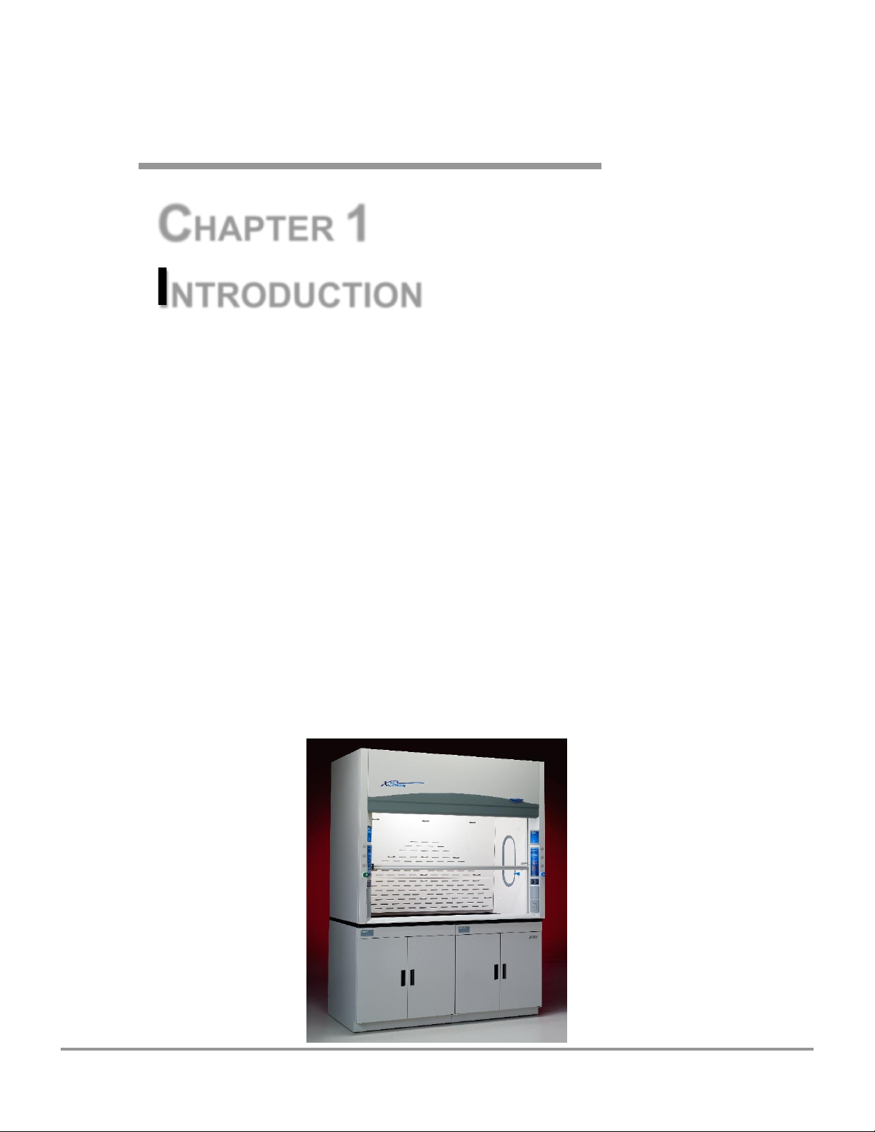
Figure 1-1
CHAPTER 1
INTRODUCTION
Congratulations on your purchase of a Labconco Protector® XStream®
Laboratory Fume Hood. Your Protector Laboratory Fume Hood is designed to
protect you by providing superior containment while conserving energy at OSHA
approved “low flow” velocities as low as 50-60 feet per minute, with test limits as
low as 40 fpm. It is the result of Labconco’s commitment to developing a high
performance fume hood and more than 60 years experience in manufacturing
fume hoods.
The Labconco Protector XStream Fume Hood has been engineered to provide
maximum containment in a laboratory, and effectively contain toxic, noxious, or
other harmful materials when properly installed. The Protector XStream offers
many unique features to enhance safety, performance, and energy savings. To
take full advantage of them, please acquaint yourself with this manual and keep it
handy for future reference. If you are unfamiliar with how high performance
fume hoods operate, please review Chapter 4: High Performance Features and
Safety Precautions before you begin working in the fume hood. Even if you are
an experienced fume hood user, please review Chapter 5: Using Your Protector
XStream, which describes your Protector XStream Hood’s features so that you
can use the hood efficiently.
Product Service 1-800-522-7658

Chapter 1: Introduction
2
Original instructions
About This Manual
This manual is designed to help you learn how to install, use, and maintain your
laboratory fume hood. Instructions for installing optional equipment on your
hood are also included.
Chapter 1: Introduction provides a brief overview of the laboratory fume hood,
explains the organization of the manual, and defines the typographical
conventions used in the manual.
Chapter 2: Prerequisites explains what you need to do to prepare your site before
you install your laboratory fume hood. Electrical and service requirements are
discussed.
Chapter 3: Getting Started contains the information you need to properly unpack,
inspect, install, and certify your laboratory fume hood.
Chapter 4: High Performance Features and Safety Precautions explains how the
Protector XStream operates and the appropriate precautions you should take when
using the fume hood.
Chapter 5: Using Your Protector XStream discusses the basic operation of your
fume hood. Information on how to prepare, use and shut down your Protector
XStream Hood are included.
Chapter 6: Maintaining Your Protector XStream explains how to perform routine
maintenance on your fume hood.
Chapter 7: Modifying Your Protector XStream explains how to modify the fume
hood or add accessories.
Chapter 8: Troubleshooting contains a table of problems you may encounter
while using your laboratory fume hood including the probable causes of the
problems and suggested corrective actions.
Appendix A: Protector XStream Hood Components contains labeled diagrams of
all of the components of the fume hoods.
Appendix B: Protector XStream Hood Dimensions contains comprehensive
diagrams showing all of the dimensions for the laboratory fume hoods.
Appendix C: Protector XStream Hood Specifications contains the electrical
requirements for laboratory fume hood. Wiring diagrams are also included.
Appendix D: Serial Number Tag Description provides current rating code used on
serial number tag
Product Service 1-800-522-7658
Chapter 1: Introduction
3
Original instructions
4'
5'
6'
!
S A 8'
Appendix E: References lists the various resources available that deal with
laboratory fume hoods.
Typographical Conventions
Recognizing the following typographical conventions will help you understand
and use this manual:
Book, chapter, and section titles are shown in italic type (e.g., Chapter 3:
Getting Started).
Steps required to perform a task are presented in a numbered format.
Comments located in the margins provide suggestions, reminders, and
references.
Critical information is presented in boldface type in paragraphs that are
preceded by the exclamation icon. Failure to comply with the information
following an exclamation icon may result in injury to the user or permanent
damage to fume hood.
Les informations critiques sont présentées en gras dans les paragraphes qui
sont précédés par l'icône d'exclamation. Ne pas se conformer aux informations
qui suivent une icône d'exclamation peut résulter à la blessure de l'utilisateur
ou à des dommages irréversibles de la hotte aspirante.
Critical information is presented in boldface type in paragraphs that are
preceded by the wrench icon. These operations should only be performed by
a trained certifier or contractor. Failure to comply with the information
following a wrench icon may result in injury to the user or permanent damage
to your hood.
Les informations critiques sont présentées en gras dans les paragraphes qui
sont précédés par l'icône de clé plate. Ces opérations devraient être seulement
exécutées par un professionnel agrée. L'échec pour se conformer aux
informations qui suivent une icône de clé plate peut résulter à la blessure de
l'utilisateur ou à des dommages irréversibles de la hotte.
Important information is presented in capitalized type in paragraphs that are
preceded by the pointer icon. It is imperative that the information contained
in these paragraphs be thoroughly read and understood by the user.
A number icon precedes information that is specific to a particular model
of laboratory fume hood. The 4' icon indicates the text is specific to the
4-foot wide model. The 5' icon indicates the text is specific to the 5-foot
model, etc.
The S icon indicates the text is specific to the standard model.
The A icon indicates the text is specific to the A-Style Combination Sash
Model.
Product Service 1-800-522-7658
Chapter 1: Introduction
4
Original instructions
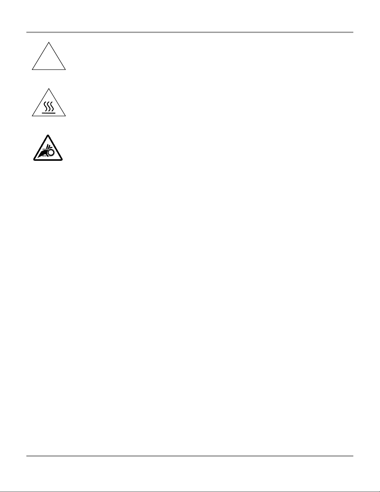
!
CAUTION – See Manual. When this symbol is on a fume hood it indicates a
caution that is detailed in this manual.
PRUDENCE – Consulter le Manuel. Quand ce symbole est sur une hotte
aspirante, il indique une prudence qui est détaillée dans ce manuel.
CAUTION – Hot Surface.
AVERTIR – Surface Chaude
CAUTION – See Manual. This symbol on the fume hood indicates the
possibility of a pinch hazard.
PRUDENCE – Consulter le Manuel. Ce symbole sur la hotte indique la
possibilité d'un risque de pincement.
Your Next Step
If your Fume Hood needs to be installed, proceed to Chapter 2: Prerequisites to
ensure your installation site meets all of the requirements. Then, go to Chapter 3:
Getting Started for instructions on how to install your laboratory fume hood and
make all of the necessary connections.
If you would like to review how Labconco’s high performance laboratory fume
hoods operate, go to Chapter 4: Performance Features and Safety Precautions.
For information on the operational characteristics of your laboratory fume hood,
go to Chapter 5: Using Your Protector XStream.
If your laboratory fume hood is installed and you need to perform routine
maintenance on the cabinet, proceed to Chapter 6: Maintaining Your Protector
XStream.
For information on making modifications to the configuration of your fume hood,
go to Chapter 7: Modifying Your Protector XStream.
Refer to Chapter 8: Troubleshooting if you are experiencing problems with your
fume hood.
Product Service 1-800-522-7658

5
Original instructions
CHAPTER 2
PREREQUISITES
Before you install your laboratory fume hood, you need to prepare your site for
installation. Carefully examine the location where you intend to install your
hood. You must be certain that the area is level and of solid construction. In
addition, a dedicated source of electrical power must be located near the
installation site.
Carefully read this chapter to learn the requirements for your installation site:
The location requirements.
The support requirements.
The exhaust requirements.
The electrical power requirements.
The service line requirements.
The space requirements.
Refer to Appendix B: Protector XStream Dimensions for complete fume hood
dimensions.
Refer to Appendix C: Protector XStream Specifications for complete laboratory
fume hood electrical and environmental conditions, specifications and
requirements.
Product Service 1-800-522-7658

Chapter 2: Prerequisites
6
Original instructions
!
!
Location Requirements
The fume hood should be located away from traffic patterns,
doors, windows, fans, ventilation registers, and any other airhandling device that could disrupt its airflow patterns. All
windows in the room should be closed.
La hotte aspirante devrait être localisé loin des voies de
circulation, des portes, des fenêtres, des ventilateurs, des
bouches de ventilation, et de tout appareil qui pourrait
interrompre ses voies de flux d'air. Toutes les fenêtres dans la
pièce devraient être fermées.
Support Requirements
DO NOT install the fume hood on a cart, dolly, or mobile
bench. ALL Protector XStream Hood installations must be
permanent and stationary. The supporting structure usually
consists of a base cabinet and chemically resistant work
surface.
NE PAS installer la hotte aspirante sur un chariot ou un banc
mobile. TOUTES les installations de la Hotte Protecteur
doivent être permanentes et fixes. La structure de soutien
consiste habituellement en un meuble doté d’une surface de
travail chimiquement résistante.
Exhaust Requirements
The exhaust duct connection has been designed for 12" nominal duct (12.75" OD)
to allow for minimum static pressure loss while operating at 50 to 100 fpm face
velocities. The 12" diameter exhaust duct also allows for proper transport
velocities away from the hood with minimal static pressure loss. Should higher
transport velocities of 1000 fpm to 2500 fpm be required, simply install a reducer
after the exhaust outlet. The exhaust volume and fume hood static pressure loss
are listed for each hood model at two sash heights and for face velocities from 40
to 100 fpm. When sizing the exhaust requirements, the choice must be made for
air foil, sash height and face velocity.
Product Service 1-800-522-7658
Chapter 2: Prerequisites
7
Original instructions
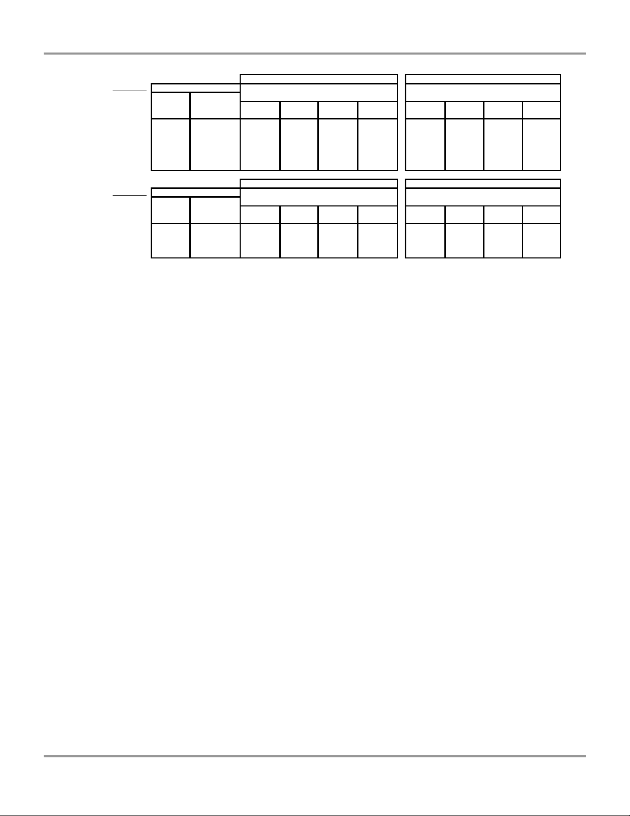
Projected Airflows and Static Pressure
Eco Energy Saving Air Foil Flush Air Foil
Hood Type Face Velocity (fpm) Airflow Volumetric Rate (CFM) @ Airflow Volumetric Rate (CFM) @
Sash at Sash at 62.5% Static Pressure (inches of water) Static Pressure (inches of water)
Full open open 4' 5' 6' 8' 4' 5' 6' 8'
at 28" at 18" Hood Hood Hood Hood Hood Hood Hood Hood
XSTREAM 100 160 705, 0.26" 930, 0.32" 1150, 0.41" 1600, 0.29" 740, 0.28" 975, 0.34" 1205, 0.44" 1675, 0.31"
80 128 565, 0.17" 745, 0.20" 920, 0.26" 1280, 0.19" 590, 0.18" 780, 0.22" 965, 0.28" 1340, 0.20"
60 96 425, 0.09" 560, 0.12" 690, 0.15" 960, 0.10" 445, 0.10" 585, 0.12" 725, 0.16" 1005, 0.11"
50 80 350, 0.06" 465, 0.08" 575, 0.10" 800, 0.07" 370, 0.07" 490, 0.08" 605, 0.11" 840, 0.08"
40 64 280, 0.04" 370, 0.05" 460, 0.07" 640, 0.05" 295, 0.05" 390, 0.06" 480, 0.07" 670, 0.05"
Eco Energy Saving Air Foil Flush Air Foil
Hood Type Face Velocity (fpm) Airflow Volumetric Rate (CFM) @ Airflow Volumetric Rate (CFM) @
Sash at Sash at Static Pressure (inches of water) Static Pressure (inches of water)
62.50% Full open 4' 5' 6' 8' 4' 5' 6' 8'
open at 18" at 28" Hood Hood Hood Hood Hood Hood Hood Hood
XSTREAM 100 62 440, 0.10" 580, 0.12" 720, 0.16" 1000, 0.11" 475, 0.11" 625, 0.13" 775, 0.17" 1075, 0.12"
80 50 350, 0.06" 465, 0.08" 575, 0.10" 800, 0.07" 380, 0.07" 500, 0.08" 620, 0.11" 860, 0.08"
60 38 265, 0.04" 350, 0.05" 430, 0.06" 600, 0.04" 285, 0.04" 375, 0.05" 465, 0.06" 645, 0.04"
Proper blower selection can be determined from these exhaust requirements and
the total system static pressure loss. Contact Labconco Customer Service for
assistance in sizing a remote blower system.
Electrical Requirements
The Protector XStream Hood models feature internal wiring for the LED light
assembly and light switch. All internal wiring is terminated at the single point
wiring junction box for hook-up by a qualified electrician. The blower switch,
and light switch wires are also terminated at the single point wiring junction box
for hook-up by a qualified electrician. Refer to Chapter 3: Getting Started and
Appendix C: Protector XStream Specifications for the wiring diagram for proper
electrical installation.
Les modèles Protector XStream Hood sont dotés d'un câblage interne pour
l'éclairage LED et l'interrupteur. Tout le câblage interne est terminé à la boîte de
jonction point de câblage unique pour le raccordement par un électricien qualifié.
Le bouton du ventilateur, et fils de l'interrupteur de lumière sont également mis
fin à la boîte de jonction point de câblage unique pour le raccordement par un
électricien qualifié. Reportez-vous au Chapitre 3: Mise en route et à l'Annexe C:
Spécifications Premier Protector pour le schéma de câblage pour l'installation
électrique correcte.
Product Service 1-800-522-7658

Chapter 2: Prerequisites
8
Original instructions
Service Line Requirements
All service lines to the laboratory fume hood should be ¼ inch outside diameter,
copper (brass for natural gas), and equipped with an easily accessible shut-off
valve, should disconnection be required. Recommended operating pressure is 40
PSI, with a maximum allowable pressure of 200 PSI. Consider a pressure
regulator to reduce line pressure to 40 PSI. Please check with local codes for
other requirements.
Space Requirements
The dimensions for the different models are shown in Appendix B: Protector
XStream Dimensions.
Product Service 1-800-522-7658

9
Original instructions
!
CHAPTER 3
GETTING STARTED
Now that the site for your laboratory fume hood is properly prepared, you are
ready to unpack, inspect, install, and certify your unit. Read this chapter to learn
how to:
Unpack and move your Protector Hood.
Set up the fume hood with the supporting structure and work surface.
Connect to an exhaust system.
Connect the electrical supply source.
Connect the service lines.
Seal the Protector Hood to the work surface.
Arrange certification of your Protector Hood.
Depending upon which model you are installing, you may need common
plumbing and electrical installation tools in addition to 5/16", 3/8", 7/16", and
1/2" wrenches, ratchets, sockets, a nut driver set, a flat-blade screwdriver, a
Phillips screwdriver, and a carpenter level to complete the instructions in the
chapter.
The Protector XStream Hood models weigh between 400 to 800
lbs. (182-363 kg). The shipping skid allows for lifting with a
mechanical lift truck or floor jack. If you must lift the fume
hood manually, follow safe-lifting guidelines. Normally, the
fume hood can be slid off a hydraulic lift table and be placed
into position on top of the work surface. Do not lift by the
front air foil.
Les XStream modèles de la Hotte Protecteur pèsent entre 400 à
800 livres. (182-363 Kg). La palette bois d’envoi permet le
soulèvement par un camion muni d’un élévateur mécanique ou
par un cric rouleur. Si vous devez soulever manuellement la
hotte aspirante, respectez les règles de sécurité du soulèvement.
Normalement, la hotte aspirante peut être glissée d'une table
munie d’un élévateur hydraulique et être placée en position sur
Product Service 1-800-522-7658
Chapter 3: Getting Started
10
Original instructions
The United
States
Interstate
Commerce
Commission
rules require
that claims be
filed with the
delivery
carrier within
fifteen (15)
days of
delivery.
!
la surface de travail. Ne pas soulever par l’écoulement d'air du
devant.
Unpacking Your Laboratory Fume Hood
Carefully remove the shrink-wrap or carton on your fume hood and inspect it for
damage that may have occurred in transit. If your unit is damaged, notify the
delivery carrier immediately and retain the entire shipment intact for inspection
by the carrier.
DO NOT RETURN GOODS WITHOUT THE PRIOR
AUTHORIZATION OF LABCONCO. UNAUTHORIZED
RETURNS WILL NOT BE ACCEPTED.
IF YOUR HOOD WAS DAMAGED IN TRANSIT, YOU MUST
FILE A CLAIM DIRECTLY WITH THE FREIGHT CARRIER.
LABCONCO CORPORATION AND ITS DEALERS ARE NOT
RESPONSIBLE FOR SHIPPING DAMAGES.
Do not discard the shipping skid or packing material for your fume hood until you
have checked all of the components and installed and tested the unit. The
XStream fume hood baffles are shipped loose behind the hood and do not
discard. The lower baffle is 12.9" tall and the middle baffle is 27.4" tall. See
Figure 1-1, Figure 3-1 and Figure B-1 that shows proper XStream baffle
installation. Do not remove the fume hood from its shipping skid until it is ready
to be placed into its final location. Move the unit by placing a flat, low dolly
under the shipping skid, or by using a floor jack.
Do not move the hood by tilting it onto a hand truck.
Ne pas déplacer la hotte en le penchant sur un diable.
Removing the Shipping Skid
LEAVE THE FUME HOOD ATTACHED TO ITS SHIPPING
SKID UNTIL IT IS AS CLOSE TO ITS FINAL LOCATION AS
POSSIBLE. MOVE THE HOOD BY USING A SUITABLE
FLOOR JACK, OR BY PLACING A FURNITURE DOLLY
UNDERNEATH THE SKID. DO NOT MOVE THE HOOD BY
TILTING IT ONTO A HAND TRUCK.
After you verify the fume hood components, move your hood to the location
where you want to install it. Follow the steps listed next to remove the shipping
skid from your unit.
1. Remove the side panels by unscrewing the concealed screw. Then lift
off the side panels.
Product Service 1-800-522-7658
Chapter 3: Getting Started
11
Original instructions
!
!
2. Find the hardware (lag screws, etc.) that attach the fume hood to the
skid and remove the hardware. Some hardware is on the sides and
some is on the back.
Sash Weight Release
To protect the fume hood from damage in shipment, the sash weight has been
secured to the back of the fume hood with screws. Simply remove the screws and
make sure the sash cables or chains are on the pulleys or sprockets before
operating the sash. On models with more than one sash, the sash weights have
been secured to the shipping skid with lag screws. Remove the weights from the
skid and attach them to the respective sash cables or chains using the threaded
connectors provided.
NOTE: THE SASH WEIGHT ITSELF WAS INDIVIDUALLY
MATCHED FOR THIS SPECIFIC HOOD AND SHOULD NOT
BE EXCHANGED ON ANY OTHER UNIT.
Installing the Hood on a Supporting
Structure and Work Surface
The Protector Hood is heavy! Use caution when lifting or
moving the unit.
La Hotte Protecteur est lourd ! Prudence en soulevant ou en
déplaçant l'objet.
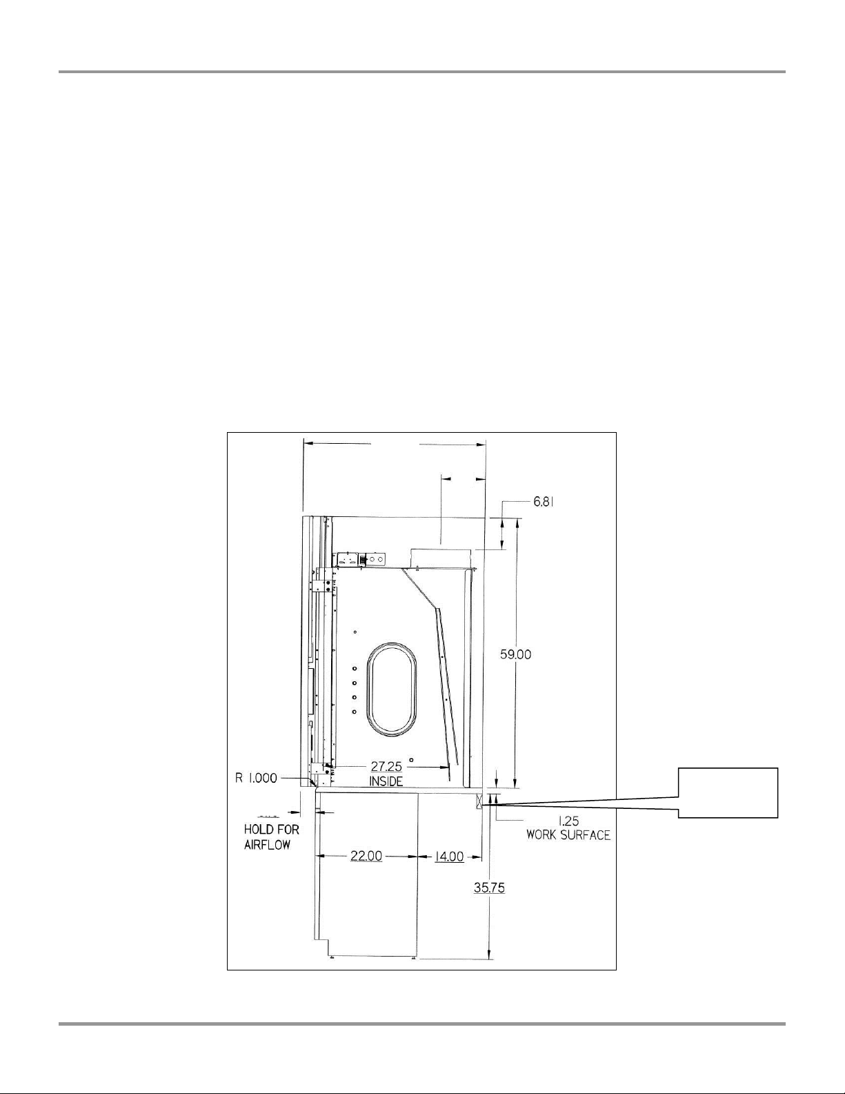
When installing the Protector XStream Fume Hood onto a chemically-resistant
work surface or benchtop, ensure that the structure can safely support the combined
weight of the fume hood and any related equipment. The work surface should be at
least as wide as the hood to properly support it. The work surface is aligned flush
with the back of the fume hood for good airflow: this will provide the correct
spacing under the air foil for proper bypass airflow. The Protector XStream with
Eco-Foil performs best with a work surface having a large 1.0" leading radius to
promote aerodynamic airflow at low velocities. The high performance XStream
work surface should have a 36" deep dimension. The lower base cabinets are placed
flush with the front of the work surface as shown in Figure 3-1.
WARNING: It is important to: 1). Support the rear of the
work surface and fume hood. 2). The cross support provides
support for the bottom of the work surface. 3). Install the
cross support after the base cabinets and work surface are
leveled and before installing the hood.
AVERTISSEMENT : Il est important de soutenir l'arrière de
la surface de travail et la hotte aspirante. Le support
Product Service 1-800-522-7658
Chapter 3: Getting Started
12
Original instructions
Place Cross
Support Here.
37.7
1.7
9.34
tranversal soutient le bas de la surface de travail. Installer le
support transversal après que les meubles et la surface de
travail soient nivelés et avant d'installer la hotte.
The following are instructions for mounting a cross support:
1. Level the base cabinets and the work surface. Work surface should be
placed flush with the back of the fume hood as shown in Figure 3-1.
2. Scribe a line on the wall or back of the base cabinet to locate the
support under the work surface.
3. Mount the support by attaching it to the wall or base cabinet.
4. Place the hood on top of the work surface and cross support.
The work surface should be smooth and durable, such as a chemical-resistant epoxy
resin. The surface should be nonporous and resistant to the acids, solvents, and
chemicals used in conjunction with the Protector XStream Fume Hood. The work
surface should also contain a dished recessed area for containing primary spills.
Figure 3-1
Product Service 1-800-522-7658
Chapter 3: Getting Started
13
Original instructions
!
!
Connecting to the Hood Exhaust System
WARNING: The weight of the exhaust ductwork system must
be supported independently of the hood superstructure. Do
not allow this weight to be supported by the hood structure as
damage to the hood may occur.
AVERTISSEMENT : Le poids du système d'aspiration de
ductwork doit être soutenu d'une manière indépendante de la
superstructure de la hotte. Au cas où ce poids est supporté par
la structure de la hotte, des dommages à la hotte peuvent
arriver.
The exhaust connection should be installed by a qualified
HVAC contractor. The exhaust connection on your hood has
been designed for 12" nominal pipe (12.75" OD) to allow for
minimum static pressure loss with proper transport velocities
away from the hood. Should higher transport velocities be
required, simply install a reducer after the hood exhaust outlet.
Consult Labconco Customer Service should you require help
sizing your blower for the exhaust volume and total system
static pressure loss.
La connexion d'échappement devrait être installée par un
professionnel de CVC agrée. La connexion d'aspiration sur
votre hotte a été conçue pour un tuyau nominal de 12 pouces
(12,75 pouces de diamètre externe) afin d’avoir une perte
minimale de pression statique avec les correctes flux de
transport loin de la hotte. Consulter le Service Clientèle de
Labconco si la calibration de votre soufflerie pour le volume
d'aspiration et la perte de pression statique du système le
requiert.
The selected exhaust duct material should match the hood
procedures and chemicals used to ensure compatibility.
Le matériel de conduit d'aspiration choisi devrait être en
conformité avec les procédures de la hotte et les produits
chimiques qui sont utilisés pour garantir la compatibilité.
Product Service 1-800-522-7658

Chapter 3: Getting Started
14
Original instructions
!
Connecting the Electrical Supply Source
to the Protector Fume Hood
Prior to connecting any electrical wiring to the fume hood structure, refer to the
hood identification plate for the proper electrical requirements of your specific
model.
WARNING: The building electrical supply system for
Protector XStream Hoods should include overload protection.
A switch or circuit breaker should be in close proximity to the
equipment and within easy reach of the operator. The switch
or circuit breaker is to be marked as the disconnecting device
for the equipment. Consult the NEC-2002 for proper
installation.
AVERTISSEMENT : Le système d’alimentation électrique de la
Hotte Protecteur doit inclure la protection contre la surcharge. Un
commutateur ou disjoncteur doit être tout près de l'équipement et
à portée facile de l'opérateur. Le commutateur ou le disjoncteur
doit être marqué comme l'appareil débranchant pour
l'équipement. Consulter le NEC-2002 pour une installation
correcte.
The identification plate, model number, serial number, and electrical connection
boxes are accessible from the front of the fume hood by removing the front panel.
The Protector XStream Hood is wired for 115 Volt, 50/60 Hz, 20 Amp or
230Volt, 50/60 Hz, 10 Amp electrical service. Check the I.D. plate behind the
front panel for voltage verification. The number of circuits varies depending on
the model. All of the electrical connections are terminated at the field wiring
terminal box for hook-up by a qualified electrician. We recommend each circuit
be a dedicated branch circuit. However, if wired together the maximum load
allowed is the sum of individual outlets plus the rating of the unit (i.e. 2 Amps).
The single point internal junction box is used for the connection of the lights,
blower, and duplex outlets. Refer to the wiring diagram for your Protector
XStream in Appendix C: Protector XStream Fume Hood Specifications.
The fume hood is required to be grounded to the MAINS protective earthing ground
for safe operation. Using a ring terminal sized for a 10-24 machine screw, connect
the MAINS ground conductor to the grounding lug marked with the protective
earthing symbol, . Only MAINS ground conductors should be connected to the
protective earthing ground lug, no other conductors should be connected to this
grounding lug. Using wire nuts connect the MAINS supply conductors to the fume
hood supply wires. Insure that the wires are connected as per the appropriate wire
color codes for the input voltage. For 115V Phase (Hot) is black and Neutral is
white, for 230V Phase1 is brown and Phase2 is blue. Refer to the wiring diagram for
your Protector XStream in Appendix C: Protector XStream Specifications.
Product Service 1-800-522-7658
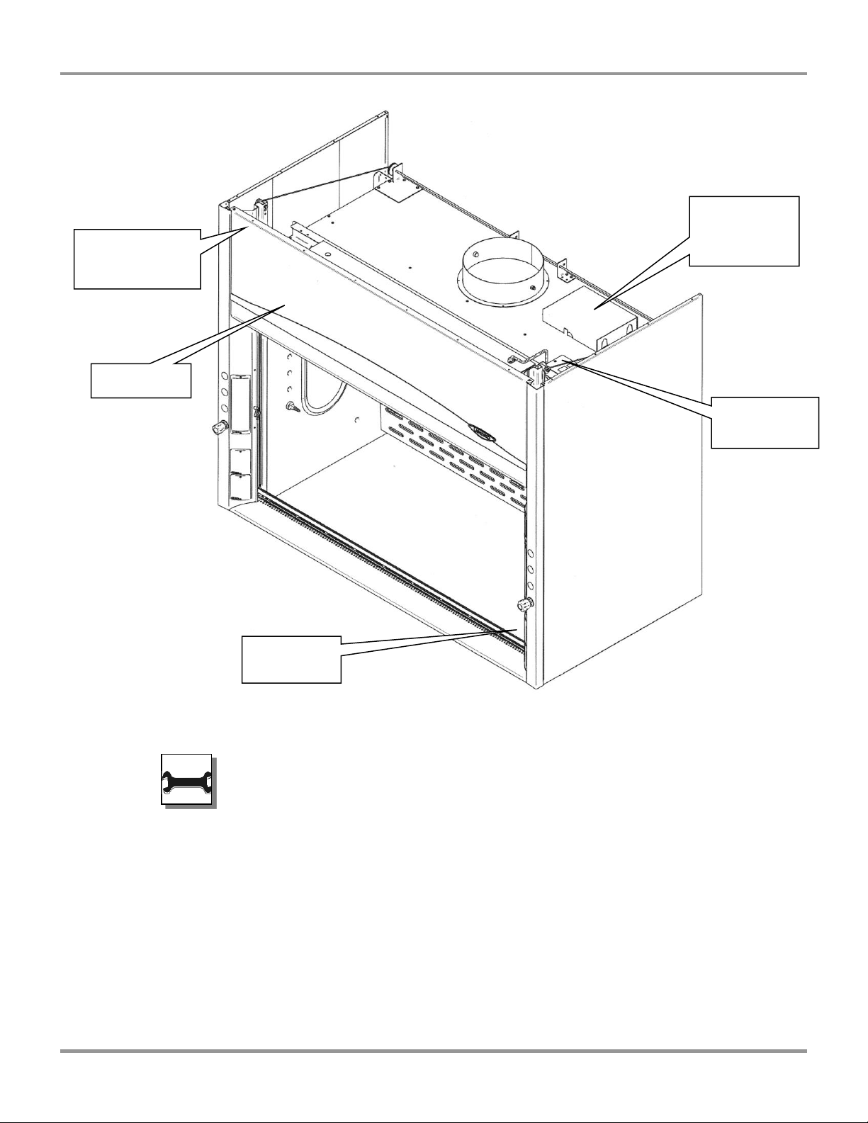
15
Original instructions
Internal
Junction Box
Primary I.D. Plate
Front Panel
Front Panel
Secondary
I.D. Label
Box Assembly,
and loose parts
Located behind
Chapter 3: Getting Started
holds manual
Figure 3-2
All wiring for the fume hood SHOULD be performed by a
licensed electrician and conform to all local codes. In most
cases, the hood will require the use of shielded conduit to
protect the wiring into the hood. The grounding connection
shall not be made to the terminal box cover.
Tout le câblage électrique pour la hotte aspirante devrait être
exécuté par un électricien agrée et être conforme à tous les
règles en vigueur. Dans la plupart des cas, la hotte exigera
l'usage de conduit blindé pour protéger le câblage électrique
dans la hotte. La prise de terre ne sera pas faite à la couverture
de la boîte du terminal.
Product Service 1-800-522-7658

Chapter 3: Getting Started
16
Original instructions
Air
Hot Water
Vacuum
Cold Water
Natural Gas – See Caution Below
!
!
!
The LED light has been mounted outside the top liner panel and is sealed from
vapors inside the hood structure. To change the LED light bulbs in your hood, you
must first remove the front panel from the hood. Next remove the knock out
plugs holding the light fixture in place. Lift fixture up and replace any defective
bulbs. Reverse order to reassemble.
Connecting the Service Lines to the
Protector Fume Hood
The hoods with service fixtures have been plumbed from the valve to the hose
connector or gooseneck for your installation convenience. A qualified installer
shall provide the tubing. Tubing can enter the hood from above, through the
back, or through the work surface to make these connections to the service
fixtures.
NOTE: Inspect all fittings for leakage. Tighten the fittings
slightly if needed.
NOTE : Inspecter toutes les installations à la recherche de
fuite. Resserrer les installations légèrement si nécessaires.
CAUTION: Do not use oxygen with any standard service
fixture. Contact Labconco Customer Service for oxygen
fixture information.
PRUDENCE : Ne pas utiliser de l'oxygène avec l'accessoire de
service standard. Contacter le Service Clientèle de Labconco
pour les informations d'accessoire d'oxygène.
Should access to the hood plumbing fixture bodies be required, remove the
service access plate on the hood front corner posts by loosening their individual
screws (see item 11, Figure A-1 in Appendix A). The valve body will now be fully
exposed for any service work that may be necessary. The service fixtures
supplied on your laboratory hood are designed for use with the following services:
WARNING: Contact Labconco Customer Service directly
before using any service other than those listed above in these
valves to assure full compatibility.
AVERTISSEMENT : Contacter le Service Clientèle de
Labconco directement avant d'utiliser n'importe quel service
autre que ceux énumérés au-dessus dans ces soupapes pour
assurer une pleine compatibilité.
Product Service 1-800-522-7658

Chapter 3: Getting Started
17
Original instructions
!
CAUTION: Natural gas should be used only in the service
fixture that has been pre-plumbed with brass tubing. Sulfur
content of the gas could cause deterioration of standard copper
supply lines.
PRUDENCE : Le gaz naturel devrait être seulement utilisé
dans l'accessoire de service qui a été pré soudé avec des tuyaux
de cuivre. Le contenu soufré du gaz pourrait causer la
détérioration des lignes d’alimentation en cuivre standard.
Sealing the Protector Hood to the Work
Surface
When the hood has been set in place, ducted, wired, and plumbed, it should be
sealed at the work surface to prevent spilled materials from collecting under the
walls of the hood. Materials such as silicone sealants are recommended to seal
the hood structure.
Certifying the Protector Fume Hood
The combination of your laboratory hood, exhaust ductwork, and exhaust blower
gives you the flexibility to change the airflow at the sash opening of your hood.
To determine the actual face velocity at the sash opening, airflow velocity
readings will need to be taken. This should be done across the sash opening of
the hood in accordance with the Industrial Ventilation Manual section on
laboratory hoods (see Appendix E: References). Labconco recommends an
average face velocity at the sash opening of 50 to 100 feet per minute for
Protector XStream high performance fume hoods. Consult Chapter 2 for proper
airflow volumes for your particular model. To ensure the performance at 50-60
feet per minute, Labconco researchers successfully challenged the Protector
XStream at face velocities lower than 50 feet per minute, under various adverse
conditions.
Your Protector Fume Hood has been tested at the factory per ASHRAE 110-1995.
All hoods achieve an “as manufactured rating” of less than 0.05 part per million
(ppm) at 4 liters per minute (lpm); AM <0.05 (consult Labconco for individual
fume hood ratings). For “field use” ASHRAE testing contact Labconco Sales
Engineering Team or Customer Service for a certified on-site contractor.
Product Service 1-800-522-7658
 Loading...