

Page 1

Protector®
Controlled Atmosphere Glove Box
INSTRUCTION MANUAL
Models 50600-00, 50700-00, 50800-00
Models 50600-02, 50700-02, 50800-02
Models 50601-00, 50701-00, 50801-00
Models 50601-02, 50701-02, 50801-02
Product designs are subject to change without notice
© 2002 Labconco Corporation
50755 Revision E / ECO A616
Printed in U.S.A.
Page 2

TABLE OF CONTENTS
Introduction
Components Shipped...................................................................... 4
General Description........................................................................ 5
Performance ................................................................................... 6
Component Identification ............................................................... 7
Installation
Location ......................................................................................... 11
Pressure Relief Bubbler .................................................................. 12
Gas and Vacuum Internal Connections ........................................... 14
Gas and Vacuum External Connections .......................................... 15
Glove Attachment .......................................................................... 20
Safety Precautions.................................................................................... 21
Normal Operation
Start Up.......................................................................................... 22
Operation of Controls ..................................................................... 22
General Operating Instructions ....................................................... 29
Routine Maintenance............................................................................... 31
Routine Maintenance Schedule....................................................... 31
Checking Pressure Relief Bubbler ..................................................31
Glove Replacement ........................................................................ 31
Fluorescent Lamp Replacement...................................................... 32
Checking Door Latch Tension ........................................................ 33
Plumbing Diagrams .................................................................................34
Wiring Diagrams...................................................................................... 37
Replacement Parts ................................................................................... 43
Accessories................................................................................................ 49
Warranty.................................................................................................. 51
Shipping Claims ....................................................................................... 52
Contacting Labconco ............................................................................... 53
Declaration of Conformity....................................................................... 54
Page 3

INTRODUCTION
Components Shipped
Carefully check the contents of the carton for damage that might have occurred in transit.
Do not discard the carton or packing material until all components have been checked against the
following component list and the equipment has been installed and tested.
As shipped, the shipping carton should contain one of the following:
Catalog No. Description
506000000 Controlled Atmosphere Glove Box, 115V, Fiberglass liner (manual pressure control)
507000000 Controlled Atmosphere Glove Box, 115V Fiberglass liner (automatic pressure
control module)
508000000 Controlled Atmosphere Glove Box, 115V, Fiberglass liner (automatic pressure
control module and automatic purge/fill control module)
506000002 Controlled Atmosphere Glove Box, 230V, Fiberglass liner (manual pressure control)
507000002 Controlled Atmosphere Glove Box, 230V, Fiberglass liner (automatic pressure
control module)
508000002 Controlled Atmosphere Glove Box, 230V, Fiberglass liner (automatic pressure
control module and automatic purge/fill control module)
506010000 Controlled Atmosphere Glove Box, 115V, Stainless steel liner (manual pressure
control)
507010000 Controlled Atmosphere Glove Box, 115V, Stainless steel liner (automatic pressure
control module)
508010000 Controlled Atmosphere Glove Box, 115V, Stainless Steel liner (automatic pressure
control module and automatic purge/fill control module)
506010002 Controlled Atmosphere Glove Box, 230V, Stainless steel liner (manual pressure
control)
507010002 Controlled Atmosphere Glove Box, 230V, Stainless Steel liner (automatic pressure
control module)
508010002 Controlled Atmosphere Glove Box, 230V, Stainless steel liner (automatic pressure
control module and automatic purge/fill control module)
4
Page 4
INTRODUCTION
AND ONE EACH OF THE FOLLOWING:
5005600 Glove Kit-Pair, Neoprene size 9-3/4 (includes 2 O-rings)
1965600 O-Ring Clamps (2)
5060300 Pressure Relief Bubbler (includes mounting hardware and 1 liter vacuum pump oil)
5079500 Connection Tube Assembly (not required on Models 508000000 and 508010000)
5075500 Instruction Manual
General Description
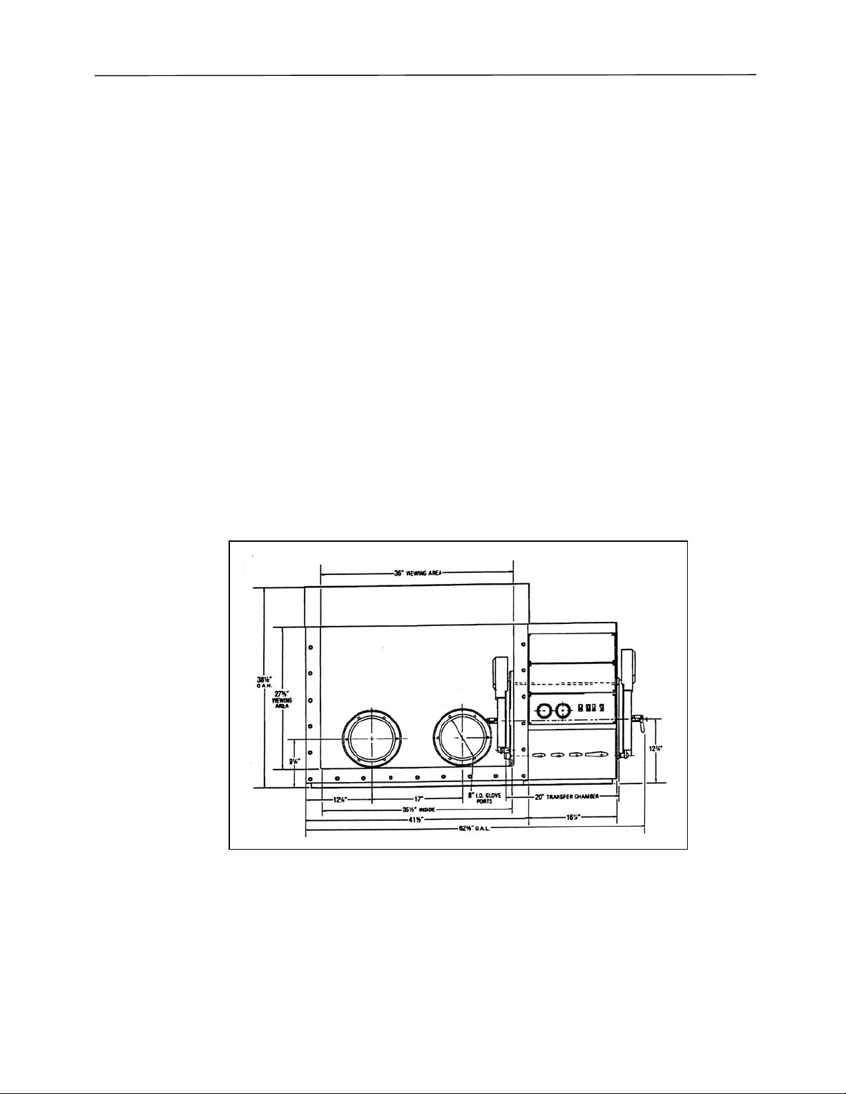
The Protector® Controlled Atmosphere Glove Box is available as a basic box with
manually controlled valves or with optional automatic systems. The basic models, 506000000 and
506010000, include a control panel with pressure gauges and switches. Models 507000000 and
507010000 include an automatic pressure control module. The pressure control module
automatically monitors and controls glove box pressure and alerts you to pressures outside preset
pressure limits. A foot pedal allows you hand-free adjustment of the glove box enclosure pressure.
Models 508000000 and 508010000 include a purge/fill control module. The purge/fill
control module automatically regulates evacuation and backfill of the transfer chamber in addition
to the basic control panel and the automatic pressure control module.
Figure 1
5
Page 5

INTRODUCTION
Performance
The Labconco Protector Controlled Atmosphere Glove Box provides an effective physical
barrier between the laboratory and the glove box interior. This barrier system results in three
distinct advantages. First, it helps protect the technician from hazardous materials. Secondly, it
protects valuable laboratory materials against the effects of ambient air and moisture. Finally, it
provides a protective, leak-tight environment as required for your research testing or production
procedures.
A transfer chamber enables samples, materials or equipment to be passed between the
laboratory and the glove box while maintaining an established glove box gas environment.
Environment Conditions
This equipment is designed to be safe under the following conditions:
• Indoor use
• Altitude up to 6562 Ft. (2000m)
• Temperature 41° to 104° (5° to 40°)
• Maximum relative humidity 80% for temperatures up to 88°F (31°C) decreasing
linearly to 50% relative humidity at 104° (40°C)
• Mains supply voltage fluctuations not to exceed ± 10% of the nominal voltage
• Transient over voltages according to Installation Categories II (Over voltage
Categories per IEC 1010)
• Pollution degrees 2 (Normally only non-conductive foreign matter, solid, liquid, or
gaseous (ionized gases), that may produce a reduction of dielectric strength or
surface resistively occurs. Occasionally, however, a temporary conductivity caused
by condensation must be expected), in accordance with IEC 664
6
Page 6

INTRODUCTION
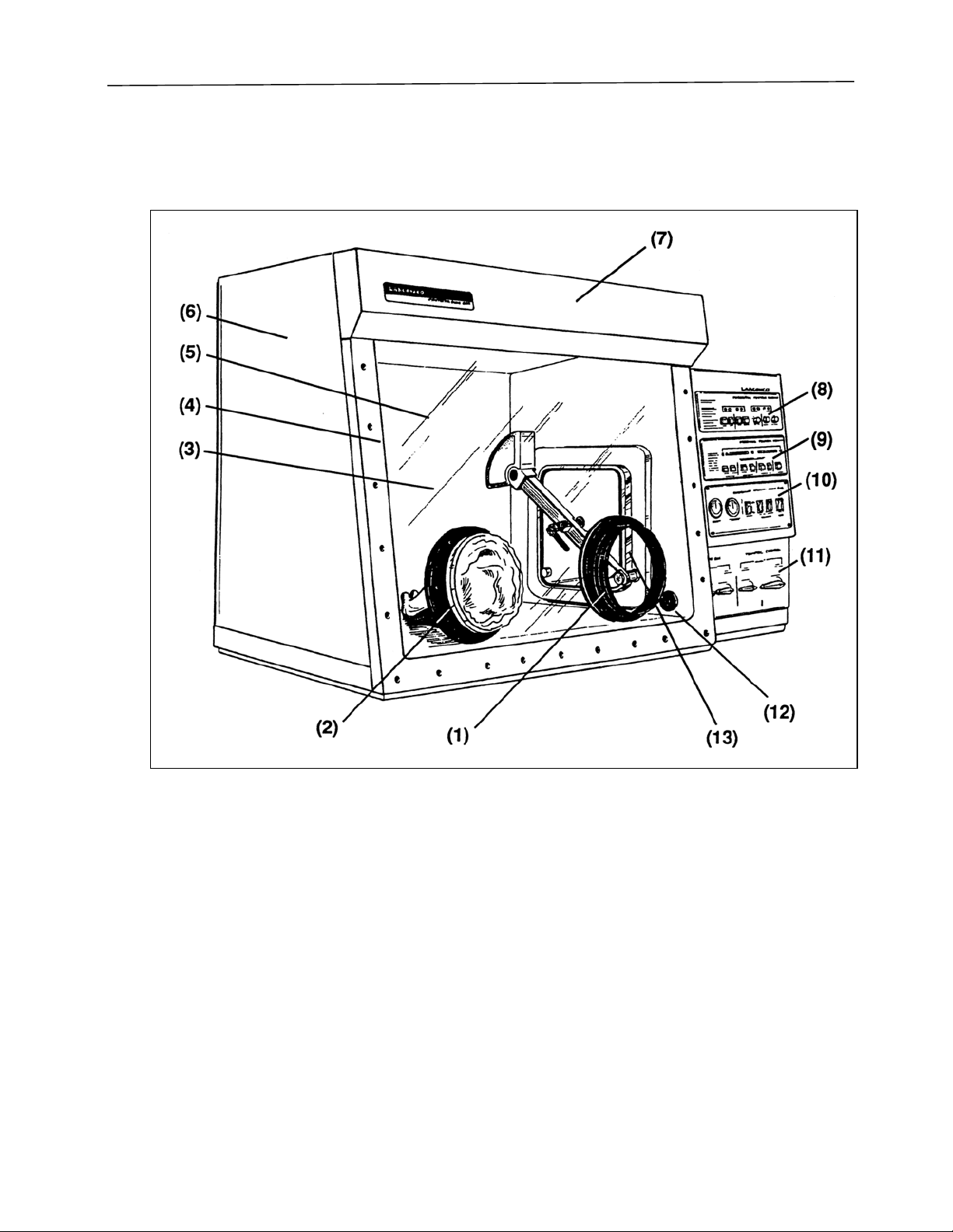
Component Identification
General components of the glove box are listed below and identified in Figure 2.
1. Glove Ports. Epoxy coated aluminum, 8" I.D. spaced 17 inches apart, sealed to viewing
window with one-piece molded neoprene gasket. Supplied with dual O-ring grooves,
neoprene gloves, retaining O-rings and clamps.
2. Neoprene Gloves. Supplied with the glove box, gloves are .015" thick neoprene, 30" long,
one pair size 9-3/4. Note: For replacement gloves see Replacement Parts, page 44.
3. Fiberglass Interior Liner (Models 506000000, 507000000 & 508000000). This liner is a
1/4" thick, one piece molded liner with _” rounded corners
3A. Stainless Steel Liner (Models 506010000, 507010000, & 508010000). This liner is of 12
gauge, type 304 stainless steel with 3/4" rounded corners.
4. Window Frame. The frame of 12-gauge epoxy coated steel, attached with 30 stainless
steel _-20 screws, is removable for full access to the interior.
5. Viewing Window. 3/8" thick laminated safety glass, mounted at 10° angle and sealed with
one-piece molded neoprene gasket. Optional 3/8" thick polycarbonate with abrasion
resistant coating available.
6. Left Side Panel. The 20-gauge epoxy coated steel side panel is easily removable for
access to glove box gas inlet port and left electrical outlet.
7. Fluorescent Lamp. One 30-watt lamp provides illumination to interior work surface equal
to 60 one-foot candles. Supplied with electrical cord and plug, the lamp may be easily
removed for bulb replacement and for access to removable viewing window.
8. Purge/Fill Control Module (Models 508000000 & 508010000 only). This module
automatically controls evacuation and backfill of transfer chamber. See figure 14, page 24.
9. Pressure Control Module (Models 507000000, 507010000, 508000000 and 508010000).
This module automatically controls the glove box pressure with a foot operated pressure
switch. Figure 12 and 13, page 22.
10. Control Panel. This panel contains gauges for glove box pressure and transfer chamber
vacuum and switches for fluorescent lamp, interior receptacles and exterior rear mounted
receptacle.
11. Manual Valves. For user control of gas input and exhaust of the glove box and the
transfer chamber. Supplied with operation label.
12. 115 Volt, 3-Wire Receptacles (Models 506000000, 506010000, 507000000, 507010000,
508000000 and 508010000). One right and one left interior receptacles, 6 amp combined
rating. Exterior switches provide separate control of each receptacle.
12A. 230Volt, 3-Wire Receptacles. One right and one left interior receptacles. Exterior
switches provide separate control of each receptacle.
13. Interior Transfer Chamber Door (Models 506000000, 507000000, 508000000).
Features 3/4" thick clear acrylic, counterweighted with quick operating latch.
7
Page 7
INTRODUCTION
13A. Interior Transfer Chamber Door (Models 506010000, 507010000, 508010000). 11
gauge type 304 stainless steel, counterweighted with quick operating latch.
Figure 2
8
Page 8

INTRODUCTION
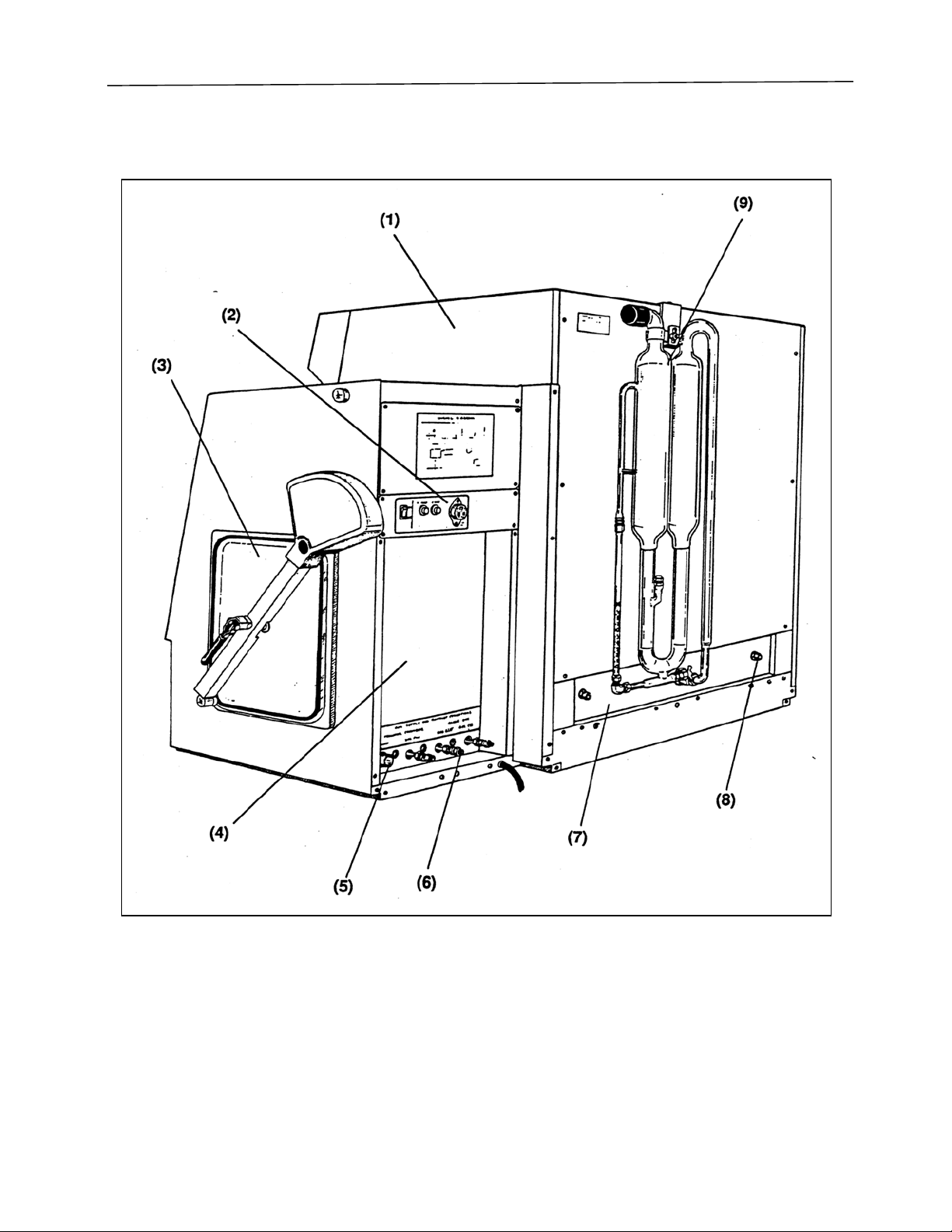
Components visible from the rear of the unit are listed below and identified in Figure 3.
1. Right Side Panel. Easily removed for access to glove box pressure gauge port.
2. Rear Electrical Panel. Contains electrical receptacle for vacuum pump operation
(controlled by front mounted switch), and two manual reset circuit breakers. The 230 volt
models are equipped with one manual reset circuit breakers.
NOTE: The rear electrical receptacle on Models 507000000, 507010000, 508000000 and
508010000, is controlled automatically by the pressure control module.
3. Exterior Transfer Chamber Door (Models 506000000, 507000000 and 508000000).
Counterweighted with a quick operating latch made of 3/4" thick clear acrylic.
3A. Exterior Transfer Chamber Door (Models 506010000, 507010000, and 508010000).
12 gauge, type 304 stainless steel counterweighted with quick operating latch.
4. Lower Rear Access Panel. Contains label to identify gas input and exhaust connections.
Removable to allow access to wiring and plumbing.
5. Vacuum Pump Connection. Accommodates the vacuum pump hose for purging the
transfer chamber (7/8" O.D. copper). NOTE: On Models 508000000 and 508010000, the
vacuum pump connection is equipped with a solenoid valve.
6. Gas Connections. Accommodates the glove box gas intake and exhaust and the transfer
chamber gas fill connections (3/8" *Swagelok® union).
NOTE: On Models 507000000, 507010000, 508000000 and 508010000, the glove box
gas intake and exhaust are equipped with solenoid valves. On Models 508000000,
508010000, the transfer chamber gas fill is also equipped with a solenoid valve.
7. Pass-through. Space provided for field installation of special fittings.
8. Fittings. For connecting optional Drying Train (catalog #5061300).
9. Pressure Relief Bubbler. Protects against equipment damage or personal injury due to
inadvertent over pressurization or decompression. Oil level may be varied to relieve
positive and negative pressure at any point between ±10" H
O.
2
NOTE: The pressure relief bubbler is shipped in a separate carton. See section on
Pressure Relief Bubbler, page 12.
*Swagelok® is a registered trademark of the Crawford Fitting Company.
9
Page 9
INTRODUCTION
Figure 3
10
Page 10
INSTALLATION
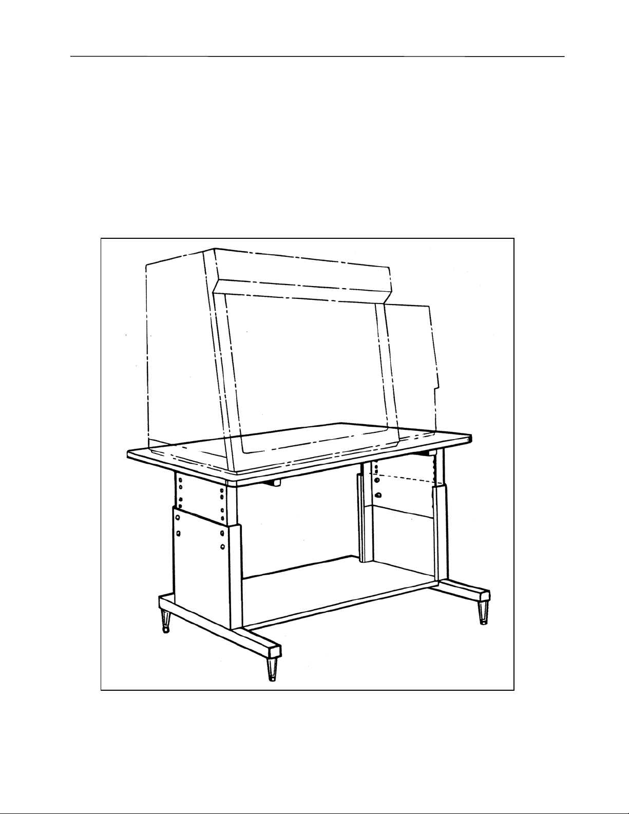
Location
The glove box should be placed on a stable, level base stand equipped with a lower shelf to
accommodate a vacuum pump near an electrical receptacle rated at 115V, 60 Hz, 20 amp for 115
volt models, or 230V, 50 Hz, 10 amp for 230 volt models. The base stand must be capable of
supporting 500 pounds minimum, and the height should provide a comfortable working position
through the glove ports. Recommended clearance between the back of the glove box and the wall
is 18 inches minimum to provide convenient access to connections on the rear of the unit. Frontal
clearance of approximately five feet should be ample to allow passage of personnel while a
technician is working at the front of the unit.
Figure 4
11
Page 11

INSTALLATION
Pressure Relief Bubbler
The Pressure Relief Bubbler operates with vacuum pump oil having a specific gravity of
0.87. The user must determine the compatibility of substances used in the glove box with vacuum
pump oil.
The Pressure Relief Bubbler is designed to relieve positive and negative pressure in the
glove box. The relief pressure point is established by the amount of oil that is poured into the
bubbler at time of installation. The oil level may be varied to relieve pressure at any point between
± 10" H2O. Recommended relief pressure is 7" H2O.
The bubbler operates on the same principle as a U-tube manometer. When pressure or
vacuum is applied to the bubbler, the oil level in one column will decrease as it increases in the
other column. The vertical difference between the two oil column levels indicates the pressure or
vacuum applied to the bubbler. When this pressure becomes sufficient to lower the oil level in one
of the columns to the level of the return bend, any additional pressure or vacuum is vented through
the full column by oil bubbling. The accumulator at the top of each column traps oil droplets in
the relief pressure air stream and prevents them from escaping the bubbler. The user must
determine whether the exhaust port of the bubbler should be filtered or vented outside the
laboratory.
CAUTION NOTES:
A. Failure to install the pressure relief bubbler may result in equipment damage or personal
injury due to inadvertent over pressurization or excessive decompression of the glove box.
B. If the bubbler exhaust is to be filtered or vented outside the laboratory, it is the user’s
responsibility to ensure that any additional airflow restriction is less than 0.5" H
O static
2
pressure.
C. In case of excessive decompression, the user must determine whether laboratory
atmosphere entering the glove box could result in fire or explosion hazards.
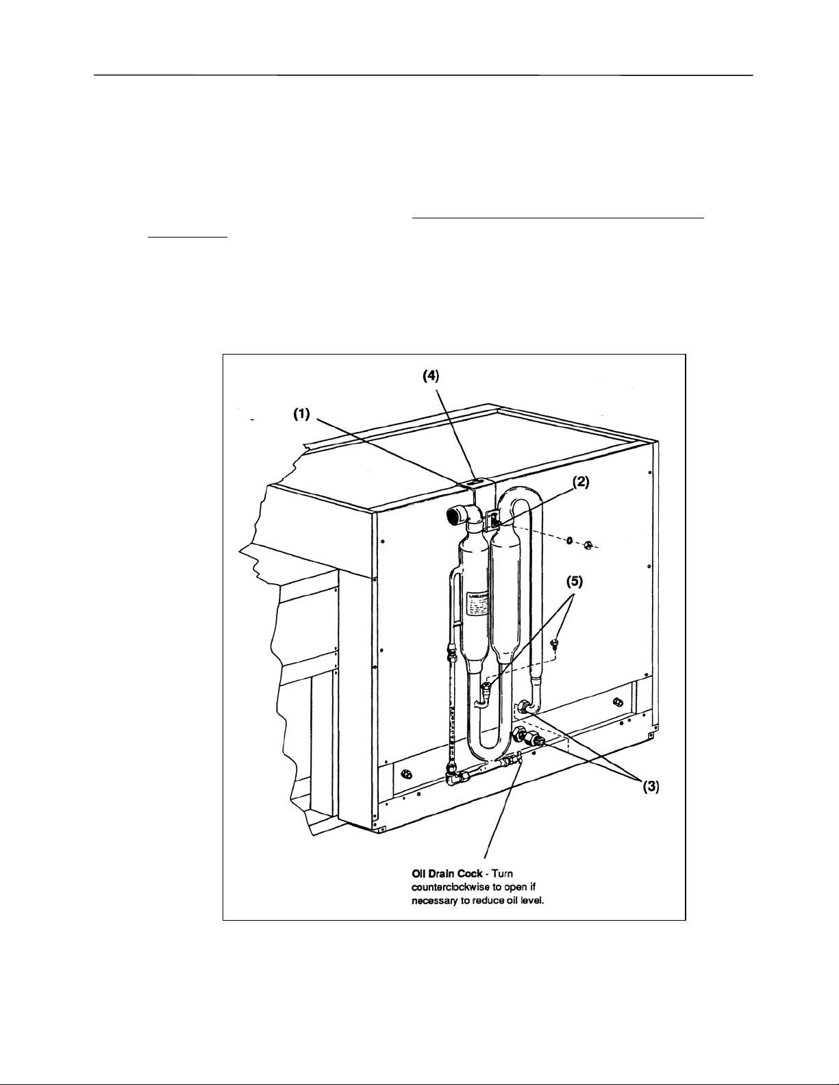
The Pressure Relief Bubbler with mounting hardware and a 1-liter bottle of vacuum pump
oil is packaged in a separate carton located above the transfer chamber. The bubbler must be
installed to avoid equipment damage or personal injury. Install according to the following steps
and refer to Figure 5.
1. Attach hanger bracket to top back edge of cabinet with #8 x 1/2" screw. Leave screw loose
to allow adjustment later.
2. Attach bubbler to hanger bracket with the nut, washer and _-20 screw (installed on the
upper cross member of the bubbler). Leave the nut untightened for later adjustment.
3. Insert lower end of bubbler into the Swagelok fitting. Make sure the bubbler tube end and
brass conical shaped ferrule enters the fitting freely with no binding. Thread the Swagelok
nut onto the fitting by hand until hand-tight. Hold the fitting with a wrench and tighten the
nut an additional _ turn.
12
Page 12
INSTALLATION
4. Hold the bubbler straight (with the vertical tubes perpendicular to the glove box base) and
tighten the top hanger bracket #8 x 1/2" screw. Secure the bubbler to the hanger bracket by
tightening the _-20 nut.
5. Remove the pipe plug from the fill spout and fill the bubbler with vacuum pump oil (.87
specific gravity) to the desired pressure relief level (must be less than 10) as indicated on
the graduated sight glass (inches H
applications. When nearing the desired fill level, add a small amount of oil at a time and
wait for it to drain into the bubbler and sight glass. When the desired level is reached,
install and tighten the fill spout plug.
NOTE: When loosening or tightening the fill plug or drain cock, be sure to hold the
bubbler’s stationary fitting with a wrench to avoid damage to the bubbler’s soldered joints.
O). The recommended level is 7 inches for most
2
Figure 5
13
Page 13
INSTALLATION
Gas and Vacuum Internal Connections (Models 506000000, 506010000, 507000000 and
507010000)
Before making gas and vacuum connections on all models except 508000000 or
508010000, determine if the transfer chamber should be backfilled with gas directly from your
inert gas supply tank or from the glove box. If the transfer chamber is to be backfilled from the
glove box on Models 506000000 and 506010000 (without automatic pressure control), it will be
necessary to throttle the glove box “gas in” manual valve and the transfer chamber “gas fill”
manual valve while the transfer chamber is filling in order to prevent excessive glove box
decompression.
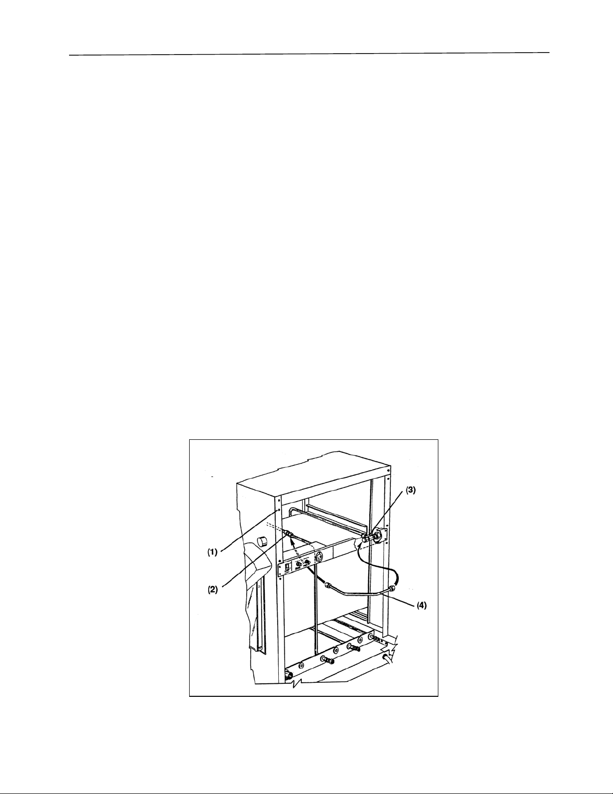
The glove box has been shipped with internal connections made for backfilling the transfer
chamber from the gas supply tank. If this is the method desired for backfilling, no other internal
connections are required. However, if you desire to backfill the transfer chamber from the glove
box, it will be necessary to make internal reconnection as follows: See Figure 6.
1. Remove rear access panels with Phillips type screwdriver.
2. Disconnect the transfer chamber “gas fill” tube from the Swagelok union located above the
transfer chamber.
3. Remove the Swagelok plug from this tee.
4. Install the tube assembly (Catalog No. 5079500) supplied with your unit.
5. Reinstall rear access panel.
Models 508000000 and 508010000 are supplied with internal connections and solenoid
valves to allow the user to select the gas source for transfer chamber backfilling by actuating “gas
source” switch on the front control panel. No internal reconnection is required.
Figure 6
14
Page 14

INSTALLATION
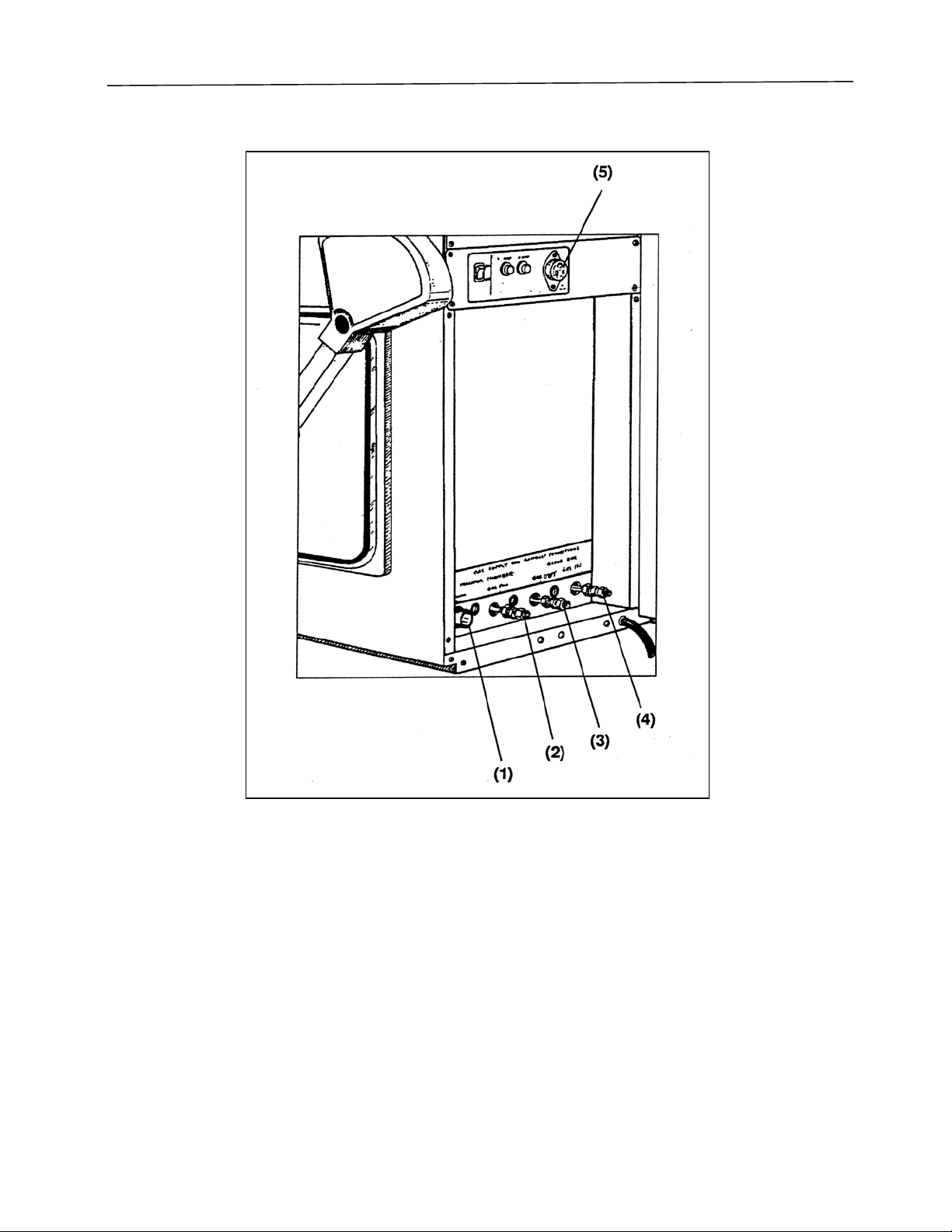
Gas and Vacuum External Connections
All gas and vacuum connections are located on the back of the transfer chamber housing
and are clearly labeled as shown in Figure 7.
1. Vacuum Pump Connection. This is a copper tube of 7/8" O.D. on Models 506000000,
506010000, 507000000, and 507010000. On Models 508000000 and 508010000, this is a
solenoid valve with 3/4" female pipe connection. Connect to your vacuum pump intake. A
vacuum pump with capacity ranging from 110-190 liters per minute is recommended. On
Models 508000000 and 508010000, this connection must be made to the vacuum pump
controlled automatically by the electrical receptacle mounted on the back of the unit.
2. Transfer Chamber Gas Fill. This is a 3/8" Swagelok connection on Models 506000000,
506010000, 507000000, and 507010000. On Models 508000000 and 508010000, this is a
solenoid valve with 3/8" female pipe connection. Connect to your inert gas supply.
NOTE: On Models 506000000, 506010000, 507000000, and 507010000, disregard this
fitting if you wish to backfill the transfer chamber from the glove box, and have made
internal reconnection as shown on Page 14.
3. Glove Box Exhaust. This is a 3/8" Swagelok connection on Models 506000000 and
506010000. On Models 507000000, 507010000, 508000000 and 508010000, this is a
solenoid valve with 3/8" female pipe connection. This allows connection to a vacuum
pump for purging the glove box or to enable the glove box to be operated under negative
pressure. On Models 507000000, 507010000, 508000000, and 508010000, this connection
must be made to the vacuum pump controlled automatically by the electrical receptacle
located on the back of the unit.
CAUTION: Each operator must determine if the glove box exhaust should be ventilated
and/or filtered for protection of health and environment.
4. Glove Box Gas Fill. This is a 3/8" Swagelok connection on Models 506000000 and
506010000. On Models 507000000, 507010000, 508000000 and 508010000, this is a
solenoid valve with 3/8" female pipe connection. Connect to your glove box inert gas
supply. Excessive gas supply pressure will cause difficulties in throttling the manual
valves on Models 506000000 and 506010000 to maintain desired glove box pressure.
5. Electrical Receptacle for Vacuum Pump. Connect the pump electrical supply cord to the
receptacle located on back of the glove box. This receptacle is controlled by the “exterior
outlet” switch on the front control panel and is protected by a manual reset circuit breaker
located on the rear panel.
NOTE: On Models 507000000, 507010000, 508000000 and 508010000, this receptacle is
automatically controlled when the front control panel switch is in the “Auto” position.
CAUTION: Each operator must determine if pump exhaust should be ventilated and/or
filtered for protection of health and environment.
15
Page 15
INSTALLATION
Figure 7
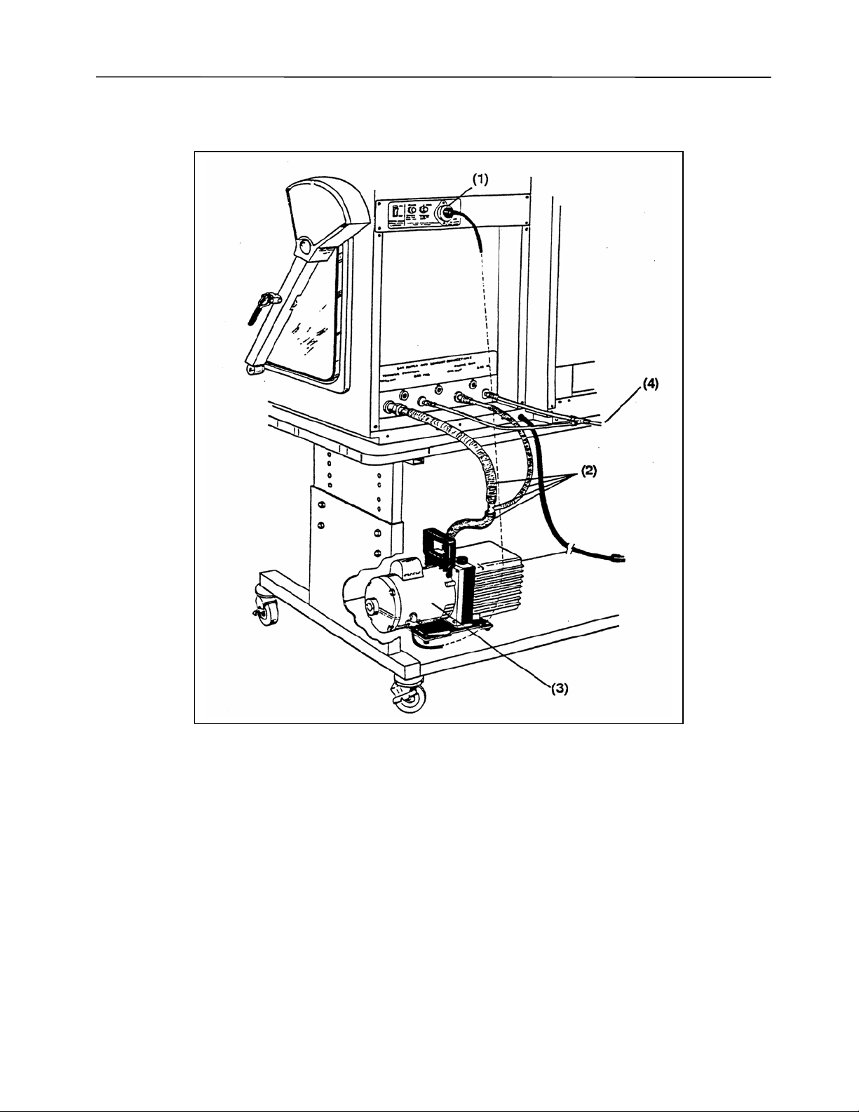
Gas and vacuum connections are illustrated for the various models in Figures 8, 9 and 10.
The illustrations show connections for models as follows: Figure 8 depicts Models 506000000 and
506010000, Figure 9 depicts Models 507000000 and 507010000, Figure 10 depicts Models
508000000 and 508010000.
16
Page 16
Models 5060000 and 5060100
INSTALLATION
Figure 8
1. Electrical Receptacle for Vacuum Pump. Controlled by the “Exterior Outlet” switch on
the front panel.
2. Vacuum Connection Kit. Labconco Catalog No. 5060600 or equivalent.
3. Vacuum Pump. Labconco Catalog No. 1467700 (190 liters/minute) or Labconco Catalog
No. 1472100 (113 liters/minute) or their equivalents.
4. Connection to Inert Gas Supply. Regulated to 15 – 20 psi.
Complete Connection Kit, Vacuum and Gas (includes 5060600). Labconco Catalog No.
5060800. See Accessories Section for list of parts provided in kits.
17
Page 17

INSTALLATION
Models 5070000 and 5070100
Figure 9
1. Electrical Receptacle for Vacuum Pump. Automatically controlled by pressure control
module.
2. Vacuum Connection Kit. Labconco Catalog No. 5060600.
3. Vacuum Pump. Labconco Catalog No. 1467700 (190 liters/minute) or Catalog No.
1472100 (113 liters/minute) or their equivalents.
4. Connection to Inert Gas Supply. Regulated to 15 – 20 psi.
Complete Connection Kit, Vacuum and Gas (includes 5060600). Labconco Catalog No.
5060900. See in Accessories Section for list of parts provided in kits.
18
Page 18

Models 5080000 and 5080100
INSTALLATION
Figure 10
1. Electrical Receptacle for Vacuum Pump. Automatically controlled by pressure control
module.
2. Vacuum Connection Kit. Labconco Catalog No. 5060600 or equivalent.
3. Vacuum Pump. Catalog No. 1467700 (190 liters/minute) or Catalog No. 1472100 (113
liters/minute) or their equivalents.
4. Connection to Inert Gas Supply. NOTE: This tubing should be no less than 5/16" inside
diameter. Insufficient gas flow volume can cause the gas inlet solenoid valve to be
inadvertently opened by vacuum when the transfer chamber gas fill solenoid opens. This
will cause gas from the glove box to flow into the transfer chamber, resulting in a decrease
of glove box pressure. Also the valve may make a chattering noise. If 5/16" I.D. tubing is
used, the gas supply regulator pressure setting of 20-25 psi should provide adequate gas
19
Page 19

INSTALLATION
volume. If smaller, more restrictive tubing is used, the regulator pressure may be increased
to 30-40 psi to provide ample flow.
Complete Connection Kit, Vacuum and Gas (includes 5060600). Catalog No. 5061100.
See Accessories Section, for list of parts provided in kits.
Glove Attachment
With glove thumbs up and right/left orientation, secure the gloves in place on the glove
ports by stretching the beaded glove cuff into the groove nearest the window. Install the 8"
diameter O-ring onto the outer groove over the glove surface. Install the band clamp over the Oring as shown in the drawing below.
Figure 11
20
Page 20

SAFETY PRECAUTIONS
The following safety precautions should be regarded when operating the Controlled
Atmosphere Glove Box.
• This product is neither designed nor intended to be an explosion-proof enclosure. It is the
responsibility of the user to determine the lower explosive limits and flammability of the
enclosed gases and other matter. The user is also responsible for using proper precautions
to prevent equipment damage or injury due to explosion or combustion.
• It is the responsibility of the user to determine the suitability of this product for the
intended applications.
• Operation of the glove box with internal pressure beyond the range ±10 inches water
column could result in cabinet damage, glass breakage or loss of the controlled atmosphere.
The Pressure Relief Bubbler is designed to prevent operation beyond this pressure range
(see Installation Instructions).
• Failure to install the Pressure Relief Bubbler may result in equipment damage or personal
injury due to inadvertent over pressurization or excessive decompression of the glove box.
• If the bubbler exhaust is filtered or vented outside the laboratory, it is the user’s
responsibility to ensure that any additional airflow restriction is less than 0.5" H2O static
pressure.
• In case of excessive decompression, the user must determine whether laboratory
atmosphere entering the glove box could result in fire or explosion hazards.
21
Page 21

NORMAL OPERATION
Start Up
• Confirm that the glove box electrical power cord is plugged into a 115 volt, 60 Hz, 20 amp
electrical power source (or 230V, 50Hz, 10 amp) as appropriate.
• Switch on the fluorescent lamp and check to make sure the bulb is working.
Operation of Controls
Pressure Control Module (Models 5070000, 5070100, 5080000 and 5080100)
A. To energize the automatic control module, actuate the pressure control power switch
located on the rear panel to the “ON” position as shown below:
REAR ELECTRICAL PANEL
Figure 12
B. Actuate the exterior outlet switch located on the front control panel to the “Auto” position
as shown below:
Switch to “AUTO” on
Model 50700
and 50800
Figure 13
22
Page 22

NORMAL OPERATION
C. The Labconco CA Glove Box is designed to operate in the range of +6 to –6 inches of
water pressure (gauge). With such a relatively small amount of pressure/vacuum setting,
outside factors can and will alter the working pressures in the box. To overcome these
factors, the Pressure Control Module will maintain the desired pressure differential with the
surrounding atmosphere. Those factors that cause change in the gauge pressure inside the
box are:
Inside temperature changes Atmosphere/Room pressure changes
Movements of the Gloves Leaks in the box
Temperature Changes in the Glove Box – The expected pressure changes due to
temperature fluctuations within the box will be in the order of 0.5 inches of water per
degree F temperature change, (at 70F). The difference from theoretical calculations can be
explained by the change in volume via moving walls and compression of the gloves. In
addition to ambient variations, any electrical equipment or endo/exothermic processes
present in the box will result in a change of gauge pressure.
Atmospheric or Room Pressure Changes – There is a direct correlation between the
atmospheric pressure and the gauge reading on the box. The indicator on the box is “gauge
pressure”, the difference from inside the box to atmospheric pressure. So, for each 1" of
mercury change in barometric pressure, there can be a change up to 13 inches of water
pressure. Pressures exerted by HVAC systems are usually small in comparison to the other
factors listed here.
Movement of the Gloves – It is readily apparent that whenever the gloves are moved, the
change in volume is sensed by the pressure gauge. Set the pressure High/Low limits at
sufficient range to accommodate normal movement within the box. You will hear the
solenoid valves energize as the pressure indicator moves beyond the limit set points.
D. Functional descriptions of the pressure control module switches and indicators are shown
on the following page.
23
Page 23

NORMAL OPERATION
Figure 14
24
Page 24

NORMAL OPERATION
Purge/Fill Control Module (Models 5080000 and 5080100)
A. To energize the purge/fill automatic control module, actuate the pressure control power
switch located on the rear panel to the “ON” position.
B. Actuate the exterior outlet switch located on the front control panel to the “AUTO”
position.
Switches and indicator functions are as shown below:
Figure 15
25
Page 25

NORMAL OPERATION
Glove Box Valves and Gauge (Models 5060000 and 5060100 with Manual Pressure Control)
Positive Pressure Operation (Refer to the diagram below)
With the inner door closed and the glove box “gas in” and “gas out” valves closed (valve
handles horizontal), open the gas supply tank valve. Then slowly open the “gas in” valve and
observe the pressure gauge. When pressure reaches +2 to +3 inches water column, close the valve.
Open the glove box “gas out” valve and turn the vacuum pump switch on to allow the pressure to
reach zero inches water column or atmospheric pressure. Then close the “gas out” valve and
switch the vacuum pump off.
Negative Pressure Operation (Refer to the diagram below)
If the glove box is to be operated under negative pressure and the exhaust is connected to a
vacuum pump, turn the vacuum pump switch on and open the “gas out” valve to reduce glove box
pressure to -2" to -3" water column, then close the “gas out” valve and turn the pump off. Open
the “gas in” valve, allowing the pressure to reach zero inches water column or atmospheric
pressure, then close the gas valve.
NOTE: On Models 5060000 and 5060100, all valves must be left closed when the glove
box is unattended.
Figure 16
26
Page 26

NORMAL OPERATION
Transfer Chamber Valves and Gauge (Models 5060000, 5060100, 5070000 and 5070100 with
Manual Pressure Control)
With inner and outer transfer chamber doors closed and latched and transfer chamber “fill”
and “vacuum” valves closed (valves handles horizontal), switch exterior outlet “ON” to start the
vacuum pump. Open the vacuum valve and observe the vacuum gauge as the transfer chamber
decompresses. When it reaches the vacuum level you plan to use for a purge level, close the
vacuum valve, turn off the pump, open the “gas fill” valve and observe as the gauge returns to
atmospheric pressure. Close the “gas fill” valve.
CAUTION: If connections have been made for backfilling the transfer chamber from the
glove box, you must also observe the glove box pressure and throttle the glove box “gas in”
valve and the transfer chamber vacuum valve to make sure the glove box pressure does not
measure below -5" water column.
NOTE: Precautions should be taken to make sure the inner transfer chamber door is
closed and sealed while purging the transfer chamber with vacuum. Failure to do so will
result in the pressure relief bubbler relieving pressure, thereby, introducing laboratory air to
the glove box.
Glove Box Valves, Gauge and Controls (Models 5070000, 5070100, 5080000 and 5080100
with Pressure Control Module)
With the inner door closed and the glove box “gas in” and “gas out” valves closed (valve
handles horizontal), open the gas supply tank valve. Adjust the high/low limit switches to indicate,
by the dim light band in the display, positive pressure between +2 and +3. Next open the “gas in”
valve. The glove box pressure, indicated by the bright light display segment, will be increased to
within +2 to +3. Adjust the high/low limit switches to a span of –2 to –3, and then open the “gas
out” valve. The glove box pressure will then be decreased to within the –2 to –3 span on the
negative display as indicated. Leave the manual valves on.
Actuate the pressure setting switches to increase or decrease the pressure momentarily
beyond the limits of the span. When you release these switches, the pressure will automatically
return to within the indicated span. Repeat this check out procedure by using the foot-operated
switch. NOTE: Take care not to exceed the range of ±5" H2O.
Adjust the high/low limit switches to a span of –1 to +1 and actuate the pressure setting
switches to give actual pressure of zero.
NOTE: On Models 5070000, 5070100, 5080000, and 5080100, the manual control valves
must remain open to provide automatic control of glove box pressure. If a malfunction occurs in
the pressure control system, the manual valves can be closed to protect the established glove box
environment.
27
Page 27

NORMAL OPERATION
Transfer Chamber Valves, Gauge and Controls (Models 5080000 and 5080100 with
Purge/Fill Control Module)
Check to see if the pressure control module is energized and the lighted pressure display is
on. If not, turn on the rear panel pressure control power switch and make sure the front panel
vacuum pump outlet switch is in the AUTO position. Also make sure both the inner and outer
transfer chamber doors are closed and latched.
A. To perform an automatic purge/fill sequence.
1. Switch the backfill gas source to the desired position.
Tank – all transfer chamber fill cycles will be from the gas supply tank.
Box – all fill cycles will be from the glove box.
Tank/Box – all fill cycles will be from the gas supply tank except the last fill will
be from the glove box.
2. Adjust the vacuum switch to the vacuum level desired for the purge cycle (usually
near the 30" Hg level).
NOTE: During the actual usage, you will be able to optimize this switch position
by observing the vacuum gauge during the purge cycle and adjust the switch to
provide the vacuum level suitable for your procedures. Turning the switch
counterclockwise increases the vacuum level.
3. Set the “Cycles” switch to select from 1 to 4 purge/fill cycles.
4. Actuate the “Start” switch.
Purge – The vacuum pump will start up and evacuation of the transfer chamber will
begin and the “Purge” indicator light will be on, continuing until the level of your
vacuum setting is reached. Observe the vacuum gauge during this cycle and check
the reading at the completion of the purge cycle. Adjust the vacuum switch if
desired to provide a different vacuum level during the next purge cycle.
Backfill – When the purge cycle has completed, the vacuum pump will stop and
backfilling of the transfer chamber will begin. At this point, one of the fill source
indicator lights will be on, indicating which backfill source switch position has been
set. This will continue until the transfer chamber has reached atmospheric pressure.
NOTE: If the gas source switch is set on “Tank”, the solenoid valve between the
glove box and transfer chamber will open for a few seconds at the end of the fill
cycle to equalize the pressure of the glove box and the transfer chamber.
B. End Indicator. This indicator will illuminate at the completion of the purge/fill cycles and
when pressures in the glove box and transfer chamber have been equalized. The inner or
outer door on the transfer chamber may then be opened. The “end” light along with
28
Page 28

NORMAL OPERATION
“sequence” indicators (the number of cycles selected) will remain lighted until the next
purge/fill cycle is started.
C. Clear Switch. Actuating this switch prevents the purge/fill cycle form progressing through
the entire sequence. The system will advance directly to the last fill cycle and then end the
sequence.
D. Manual Mode. Actuating either the “Purge” or “Fill” switch overrides all automatic
controls:
Purge Switch – Depress this switch to operate the vacuum pump and evacuate the transfer
chamber. The vacuum pump will continue operating until this switch is again depressed,
then released.
Fill Switch – Hold in this switch to fill the transfer chamber. Release the switch
intermittently (if back filling from the glove box) as necessary to ensure the glove box
pressure level does not measure below -5" H2O. Release the switch when pressure in the
transfer chamber reaches zero. Do not pressurize the transfer chamber.
General Operating Instructions
Important note: All operators of this equipment should thoroughly read and understand
the preceding information under Operation of Controls before beginning this operating
instruction section. After becoming familiar with the glove box controls, you are ready to fill the
glove box with inert gas and begin your operations.
Only the user can determine what type of atmosphere and pressure level is appropriate for
the type of work being performed. If the ill effects of air in leakage outweighed the effects of out
leakage, one would choose to operate under a positive pressure. Set the “High and Low Limits”
on the Control Panel entirely in the positive pressure range. As long as viable samples are kept in
the unit, the controls, inert gas supply, and vacuum pump should remain active. The pump and gas
are necessary to compensate for temperature/pressure swings that would cause a box to go from a
positive pressure state to a negative pressure, or vice versa.
Establishing Inert Gas Environments:
The inert gas environment may be achieved by alternately purging and filling the glove box
or by simultaneously throttling the “gas in” and “gas out” valves while gas flows through the glove
box on Models 5060000 and 5060100. On Models 5070000, 5070100, 5080000, and 5080100,
this may be done by actuating the pressure setting, “Increase” and “Decrease” switches. During
either method, observe the glove box pressure gauge to see that it remains between ±5" water
column.
Determine the appropriate pressure for your operating procedures and adjust accordingly.
Usually a comfortable glove manipulation level is between ± 0.3" to 0.8" water column.
29
Page 29

NORMAL OPERATION
NOTE: Notice that the pressure gauge changes drastically when the gloves are pulled inward or
outward. When selecting operating pressure, this must be considered to, ensure operating limits of
± 5" water column are not exceeded.
CAUTION: On Models 5060000 and 5060100 all valves must be closed when the glove box is
unattended.
To further reduce the moisture level, the optional Drying Train (Catalog #50613) may be
installed.
Transfer Procedure (Models 5060000, 5060100, 5070000 and 5070100:
1. Transfer from laboratory into glove box – Make sure the inner chamber door is closed.
Place material into the transfer chamber and close the outer transfer chamber door.
Transfer from glove box outward to laboratory – Make sure the outer door is closed. Place
material into the transfer chamber and close the inner door.
2. Turn on the vacuum pump and open the vacuum valve. Purge the chamber to the vacuum
level you have selected. Close the vacuum valve. Open the chamber “gas fill” valve and
monitor the glove box pressure if backfilling from the glove box. Do not exceed the
atmospheric pressure within the transfer chamber.
3. Repeat Step 2 as required for your operation.
4. When final backfill sequence is completed (the vacuum gauge has returned to zero
reading), open the inner or outer chamber door (depending on the direction of transfer) and
remove or position the material. Close and latch the appropriate door.
NOTE: The level of purge vacuum and the number of purge/fill sequences is determined
by the operator.
Transfer Procedure (Models 5080000 and 5080100 with Purge/Fill Control Module):
1. Transfer from laboratory into glove box - Make sure the inner chamber door is closed.
Place material into the transfer chamber and close the outer transfer chamber door.
Transfer from glove box outward to laboratory – Make sure the outer door is closed. Place
material into the transfer chamber and close the inner door.
2. Purge/Fill Cycle – On Model 5080000 and 5080100, these sequences are performed
automatically. To review the information, refer to the previous section, Operation of
Controls. See section on Transfer Chamber and Valves, page 27.
3. When final backfill sequence is completed as indicated by the “End” light, open the inner
or outer door and remove or position the material (depending on the direction of transfer).
Close and latch the appropriate door.
30
Page 30

ROUTINE MAINTENANCE
Routine Maintenance Schedule
The maintenance required to the glove box is strongly dependent upon the amount of use
and the tolerance to leakage. Highly critical or hazardous procedures dictate a more frequent
inspection. Establish a schedule and keep a record of maintenance that reasonably satisfies the
needs of the piece of equipment. Include in that schedule the following items:
Quarterly, or more frequently
• Check the oil level in the bubbler through the sight glass.
• Inspect the gloves for signs of damage or wear. Replace if necessary. See procedure
below.
• Check the closing tension of the door latches. Look for consistent and sufficient gasket
compression.
As Needed Based on the Application
• Perform leak checks
• Check Pressure Relief Bubbler. See procedure below.
• Conduct maintenance on the vacuum pump as recommended by the manufacturer.
Checking Pressure Relief Bubbler
• Bring the glove box pressure to atmospheric pressure.
• Make sure the oil level indication in the sight glass is at the pressure relief level desired for
your glove box operations. Recommended oil level is 7.
• If you want the pressure to relieve at a higher level – less than 10" H
O pressure, add
2
vacuum pump oil having a specific gravity of .87 by following the instruction described in
the Installation Section Pressure Relief Bubbler.
• If you want the pressure to relieve at a lower level, drain off some of the oil by opening the
drain cock located at the bottom of the bubbler.
• Retighten the drain cock securely.
Glove Replacement
If it becomes necessary to change gloves without disturbing the integrity of the glove box
environment, follow these steps:
• Remove the O-ring from the old glove.
• Roll the old glove cuff bead from the inner groove nearest the window to the outside
groove.
• Insert the new glove through the old glove until the fingers of both are inside the glove box.
31
Page 31

ROUTINE MAINTENANCE
• Stretch the new glove’s beaded cuff over the old glove cuff and into the groove nearest the
window.
• To remove the old glove, grasp the new glove surface and manipulate the old glove bead
free from the outer groove.
• With the other glove hand inside the box, pull the old glove into the glove box.
• Install the O-ring over the new glove onto the outer groove.
Fluorescent Lamp Replacement
• Turn the light switch off and unplug the lamp cord from the receptacle located on the
outside top of the cabinet.
• From the top of the lamp housing, remove the two Phillips-type screws attaching the lamp
assembly to the top edge of the window frame.
• Remove the lamp assembly from the unit.
• The lamp tube can then be easily removed and replaced. Replacement lamp part number
12779, fluorescent lamp #F30T12/CW/RS may be purchased from most local lighting
supply stores.
• Re-install the lamp assembly and attach with the two Phillips-type screws. Plug in the
power cord and switch on the lamp. Refer to the illustration below.
Figure 17
32
Page 32

ROUTINE MAINTENANCE
Checking Door Latch Tension
Closing the latch handle should require some firm force, indicating compression of the
rubber door seals. Seal compression and latching force can be adjusted as follows:
• First close and latch the door.
• Then using a _ inch open-end wrench, turn the door adjustment screw (located between the
door and the latch bar) clockwise to increase the seal compression and latching force. Turn
screw counterclockwise to decrease compressions. Refer to the illustration below:
Figure 18
33
Page 33

PLUMBING DIAGRAMS
Models 5060000 and 5060100
Figure 19
34
Page 34

Models 5070000 and 5070100
PLUMBING DIAGRAMS
Figure 20
35
Page 35

PLUMBING DIAGRAMS
Models 5080000 and 5080100
Figure 21
36
Page 36

Models 5060000 and 5060100 – 115 VAC, 60 Hz
WIRING DIAGRAMS
Figure 22
37
Page 37

WIRING DIAGRAMS
Models 5070000 and 5070100 – 115 VAC, 60 Hz
Figure 23
38
Page 38

Models 5080000 and 5080100 – 115 VAC, 60 Hz
WIRING DIAGRAMS
Figure 24
39
Page 39

WIRING DIAGRAMS
Models 5060000-02 and 5060100-02 – 230 VAC, 50 Hz
Figure 25
40
Page 40

Models 5070000-02 and 5070100-02 – 230 VAC, 50 Hz
WIRING DIAGRAMS
Figure 26
41
Page 41

WIRING DIAGRAMS
Models 5080000-02 and 5080100-02 – 230 VAC, 50 Hz
Figure 27
42
Page 42

REPLACEMENT PARTS
Figure 28
43
Page 43

REPLACEMENT PARTS
Ref.
No.
115066600 Glass Viewing Window
215066700 Polycarbonate Lexan Viewing Window
315067200 Window Gasket – not shown – For models with fiberglass liner
3A 1 5098400 Window Gasket – not shown – For models with stainless steel liner
415005500 Kit: 8-1/2 Size Neoprene Gloves (1 pr) O-Rings (2)
51 Pr 1640500 8-1/2 Size Neoprene Gloves
615005501 Kit: 8-1/2 Size Butyl Gloves (1 pr), O-Rings (2)
71 Pr 1640501 8-1/2 Size Butyl Gloves
815005502 Kit: 8-1/2 Size Hypalon Gloves (1 pr), O-Rings (2)
91 Pr 1640502 8-1/2 Size Hypalon Gloves
10 1 5005600 Kit: 9-3/4 Neoprene Gloves (1), O-Rings (2)
11 1 Pr 1640600 9-3/4 Size Neoprene Gloves
12 1 5005601 Kit: 9-3/4 Size Butyl Gloves (1 pr), O-Rings (2)
13 1 Pr 1640601 9-3/4 Size Butyl Gloves (1 Pr)
14 1 5005602 Kit: 9-3/4 Size Hypalon Gloves (1 Pr.), O-Rings (2)
15 1 Pr 1640602 9-3/4 Size Hypalon Glove (1 Pr)
16 1 Pr 1640000 O-Rings for Gloves
17 1 Pr 1965600 Clamps, for Gloves
18 1 1361500 Pressure Gauge, ± 5" H2O
19 1 1361600 Vacuum Gauge, 0-30" Hg
20 3 1361900 3/8" Valve
21 1 1361901 1/2" Valve
22 3 1329700 Switch, SPST, 115V
22A 3 1301500 Switch, DPST, 230V
23 1 1329701 Switch, SPDT, 115V
23A 1 1301501 Switch, DPDT, 230V
24 1 5064200 Transfer Chamber Door Gasket – For models with fiberglass liner
24A 1 5098300 Transfer Chamber Door Gasket – For models with stainless steel liner
25 1 1248400 External Receptacle, 115V
25A 1 1290900 External Receptacle, 230V
26 1 1327201 Circuit Breaker, 10 Amp, 115V
26A 1 1291200 Circuit Breaker, 10 Amp, 230V
27 1 1327203 Circuit Breaker, 6 Amp, 115V
28 1 5077501 Pressure Control Module – Models 5070000, 5070100, 5080000 and
29 1 5080501 Purge/Fill Control Module – Models 5080000 and 5080100 only*
30 1 5060300 Kit, Pressure Relief Bubbler
A Glove Port Components – detailed on page 45
B Sealed Receptacle Components – detailed on page 45
C Fluorescent Lamp Assembly – detailed on page 46
D Inner Door Assembly – detailed on page 47
E Outer Door Assembly – detailed on page 48
*For solenoid valves and pressure transducer refer to Plumbing Diagrams
Qty. Catalog No. Description
5080100*
44
Page 44

Glove Ports
REPLACEMENT PARTS
Ref.
No.
115074201 Glove Port
215074301 Glove Port Mounting Ring
315066800 Glove Port Gasket
411889310 Glove Port Mounting Screw
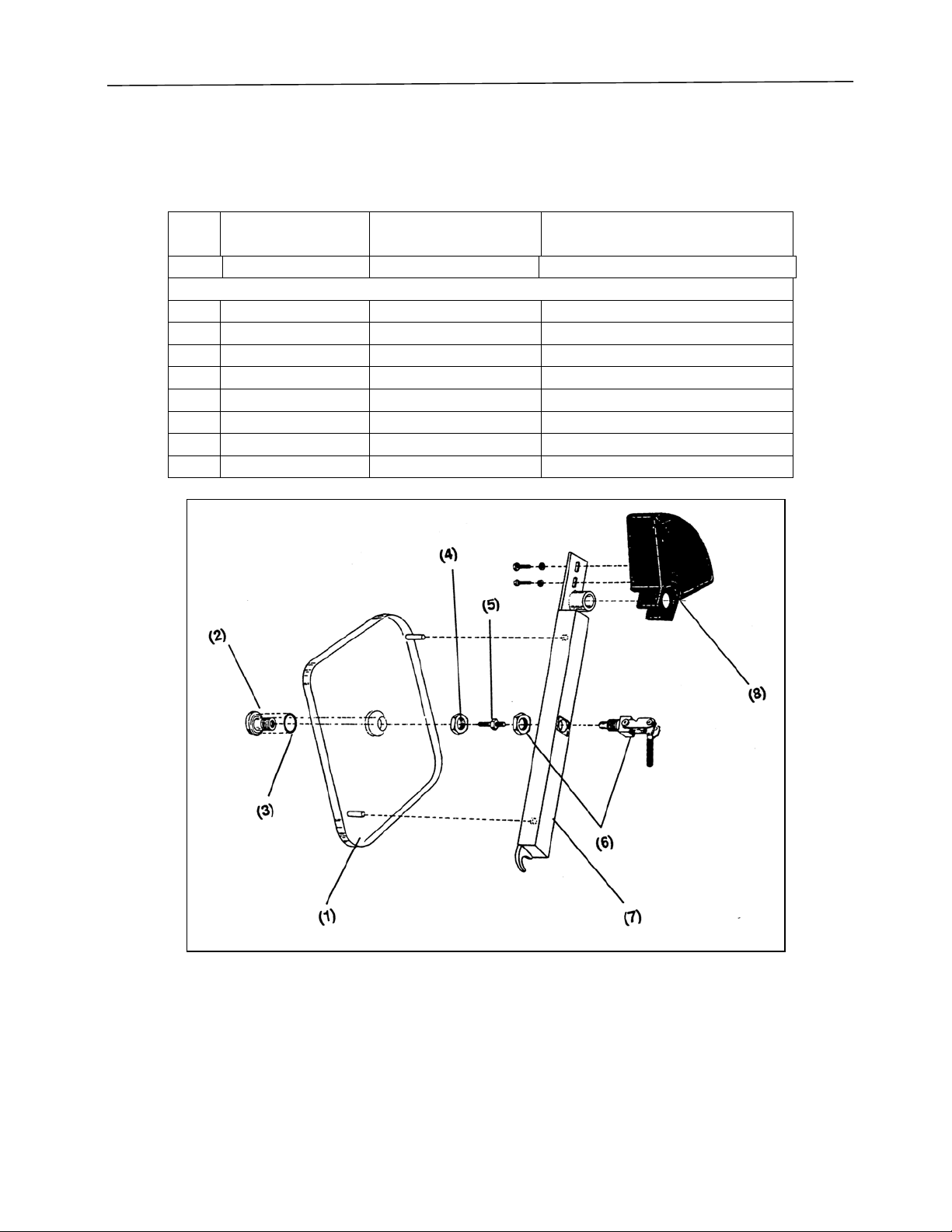
Sealed Receptacle Assembly
Qty. Catalog No. Description
Figure 29
Ref.
No.
115075600 Sealed Receptacle, 115V
1A 1 5102100 Sealed Receptacle, 230V
211645702 Receptacle O-Ring
311349100 Cupped Washer
411349200 Locknut
Qty. Catalog No. Description
Figure 30
45
Page 45

REPLACEMENT PARTS
Fluorescent Lamp Assembly (Complete with Bulb), No. 5072602 (115V) or No. 5072603
(230V)
Ref.
No.
111277900 Lamp Bulb #F30T12/CW/RS (also available locally)
215072700 Lamp Fixture Assembly – 115V
2A 1 5072701 Lamp Fixture Assembly – 230V
315072901 Lamp Housing
Qty. Catalog No. Description
Figure 31
46
Page 46

REPLACEMENT PARTS
Inner Door Assembly
No. 5067701 (Used on 5060000, 5070000, 5080000 with fiberglass liners) or No. 5098500
(Used on 5060100, 5070100, 5080100 with stainless steel liners).
Ref.
No.
Note: Acrylic and stainless steel doors are not interchangeable
1 5102800 5097900 Inner Door Assembly
2 5064500 Door Fitting
3 1645701 Door O-Ring
4 1927000 Nut, Stainless Steel _=16
5 5064600 5064600 Door Adjusting Screw
6 5068600 5068600 Door Clamp
7 5085201 5085201 Inside Latch Bar Assembly
8 5074401 5074401 Inside Counterweight
9 5098100 Grab Knob
Catalog No. Catalog No. Description
Acrylic 5067701) Stainless Steel 509850
Figure 32
47
Page 47
REPLACEMENT PARTS
Outer Door Assembly
No. 5068401 (Used on 5060000, 5070000, 5080000 with fiberglass liners) or No. 5098600
(Used on 5060100, 5070100, 5080100 with stainless steel liners).
Ref.
No.
Note: Acrylic and stainless steel doors are not interchangeable
1 5102900 5097500 Outer Door Assembly
2 5064500 Door Fitting
3 1645701 Door O-Ring
4 1927000 Nut, Stainless Steel _-16
5 5064600 5064600 Door Adjusting Screw
6 5068600 5068600 Door Clamp
7 5085301 5085301 Outside Latch Bar Assembly
8 5074501 5074501 Outside Counterweight
Catalog No. Catalog No. Description
Acrylic 5068401 Stainless Steel 5098600
Figure 33
48
Page 48

ACCESSORIES
Accessory
Part#
5061600 Interior Storage Shelves
5062000 Glove Box Mobile Stand
5062001 Glove Box Stand
5060400 Interior Glove Port Cover
Description
Three epoxy coated stainless steel storage shelves are attached to
stainless steel upright supports. Shelves are adjustable height,
measuring 6" D x 30" W x 21-1/2" H. Components may be passed
through the transfer chamber and assembled within the Glove Box
enclosure. Installation by customer.
Welded steel construction, epoxy coated with black phenolic
laminate top surface. 1/1/8" thick x 30" D x 60" W, height adjustable
from 30 to 37 inches. Lower storage shelf provides convenient space
for vacuum pump and optional drying train. Accessory includes 5"
swivel casters with locking brakes.
Same as above except furnished with adjustable leveling feet instead
of casters.
12 gauge stainless steel with molded rubber self-centering gasket and
spring-loaded latches with adjustable closure knob. Use for internal
sealing of glove port in event of worn or damaged gloves.
5060500 Exterior Glove Port Cover
12 gauge stainless steel with molded neoprene self-centering gasket.
Adjustable tension knob with latching bar attaches to port mounting
ring screw adaptors. Use to reduce leakage due to permeation of
gloves when glove box is not in use, but interior atmosphere is
maintained.
5061300 Drying Train
Enables you to reduce humidity within the Glove Box to
approximately 5 PPM. Uses a stainless steel column filled with
molecular sieve with recirculation provided by a leak tight diaphragm
pump. Consult factory for more details.
1467700 Vacuum Pump (190 Liters/Minute)
115 VAC, 60 Hz, 6.3 Amps. 113 liters per minute pumping capacity
with gas ballast. Blank off pressure of 0.2 microns.
1472100 Vacuum Pump (113 Liters/Minute)
115VAC, 60 Hz, 6.3 Amps. 113 liters per minute pumping capacity
with gas ballast. Blank off pressure of 0.2 microns.
5060600 Vacuum Connection Kit
For connecting Glove Box exhaust in parallel with transfer chamber
49
Page 49

ACCESSORIES
and vacuum pump. It includes the following components:
• Neoprene vacuum tubing, 3/4" I.D. x 3/8" wall x 3 ft long
• Neoprene vacuum tubing, 3/4" I.D. x 3/8" wall x 12" long
• Stainless steel reducing elbow/tee, 7/8" x 7/8" x 3/8"
• Vacuum tubing, 5/16" I.D. x 3/16" wall x 6 ft long
• Copper tubing, 3/8" O.D. x 12" long, to connect with the
Glove Box exhaust Swagelok fitting.
5060800 Complete Connection Kit, Vacuum and Gas
For models 506000000 and 506010000, Kit includes:
• Vacuum Connection Kit 5060600
• Copper tubing 3/8" O.D. x 15 ft.
• Brass tee, Swagelok 3/8"
5060900 Complete Connection Kit, Vacuum and Gas
For models 507000000 and 507010000. Kit includes:
• Vacuum Connection Kit 5060600
• Copper tubing 3/8" O.D. x 15 ft
• Brass tee, Swagelok, 3/8"
• Swagelok connector, 3/8" tube x 3/8" male pipe (2)
5061100 Complete Connection Kit, Vacuum and Gas
For models 508000000 and 508010000 Kit includes:
• Vacuum Connection Kit 5060600
• Copper tubing 3/8" O.D. x 15 ft.
• Brass Tee, Swagelok, 3/8"
• Swagelok connector, 3/8" tube x 3/8" male pipe (3)
• Copper tube, 7/8" O.D. x 5"
• Swagelok connector, 7/8" tube x 3/4" male pipe.
50
Page 50

WARRANTY
We are committed to providing our customers with quality equipment and service after the sale.
Part of this objective involves keeping you informed of changes and new product additions. We,
therefore, request that you take a moment to fill out the product registration card so we many know
your location as well as some of the reasons that prompted you to purchase our product.
Labconco provides a warranty on all parts and factory workmanship. The warranty includes areas
of defective material and workmanship, provided such defect results from normal and proper use
of the equipment.
The warranty for all Labconco products will expire one year from date of installation or two years
from date of shipment from Labconco, whichever is sooner, except the following:
• Purifier® Delta® Series Biological Safety Cabinets carry a three-year warranty from date
of installation or four years from date of shipment from Labconco, whichever is sooner.
• Carts carry a lifetime warranty.
• Glassware is not warranted from breakage when dropped or mishandled.
This limited warranty covers parts and labor, but not transportation and insurance charges. In the
event of a warranty claim, contact Labconco Corporation or the dealer who sold you the product.
If the cause is determined to be a manufacturing fault, the dealer or Labconco Corporation will
repair or replace all defective parts to restore the unit to operation. Under no circumstances shall
Labconco Corporation be liable for indirect, consequential, or special damages of any kind. This
statement may be altered by a specific published amendment. No individual has authorization to
alter the provisions of this warranty policy or its amendments. Lamps and filters are not covered
by this warranty. Damage due to corrosion or accidental breakage is also not covered.
WARNING: The disposal and/or emission of substances used in connection with this equipment
may be governed by various federal, state or local regulations. All users of this equipment are
urged to become familiar with any regulations that apply in the user’s area concerning the
dumping of waste materials in or upon water, land or air and to comply with such regulations.
51
Page 51

SHIPPING CLAIMS
If a shipment is received in visibly damaged condition, be certain to make a notation on the
delivering carrier’s receipt and have their agent confirm the damage on your receipt. Otherwise,
the damage claim may be refused.
If concealed damage or pilferage is discovered, notify the carrier immediately and retain the entire
shipment intact for inspection. Interstate Commerce Commission rules require that the claim be
filed with the carrier within 15 days after delivery.
NOTE: Do not return goods. Goods returned without prior authorization will not be accepted.
Labconco Corporation and its dealers are not responsible for shipping damage. Claims must be
filed directly with the freight carrier by the recipient. If authorization has been received to return
this product, by accepting this approval, the user assumes all responsibility and liability for
biological and chemical decontamination and cleansing. Labconco reserves the right to refuse
delivery of any products, which do not appear to have been properly cleaned and/or
decontaminated prior to return.
52
Page 52

CONTACTING LABCONCO
If you have any questions that are not addressed in this manual, or if you need technical assistance,
please contact Labconco’s Sales Information Department at 1-800-821-5525, and Service
Information at 1-800-522-7658 or 1-816-333-8811, between the hours of 7:00 a.m. and 6:00 p.m.
Central Standard Time.
Labconco’s mailing address is:
Labconco Corporation
8811 Prospect Avenue
Kansas City, Missouri 64132-2696
Fax # 816-363-0130
Visit Labconco through the Internet at:
http://www.labconco.com
or
Email: labconco@labconco.com
53
Page 53

54
 Loading...