

Page 1

LABCONCO CORPORATION 8811 Prospect Ave, Kansas City, MO 64132
(816) 333-8811, Fax (816) 363-0130, (800) 821-5525
Pressure Controller Operating Instructions
General Description
These operating instructions are designed for the operation of the Pressure Controller used with
Labconco’s Precise Glove Boxes. The Pressure Controller performs three automatic modes on
the glove box. First, it cycles the purging/filling process in the main glove box chamber and
transfer chamber up to 199 cycles. Second, it regulates vacuum/pressure between -5 and +5
inches of water gauge in the main glove box chamber through the glove box pressure control
program mode. Third, it regulates vacuum in the transfer chamber between 0 and -29 inches of
mercury during the purging/filling process.
Models covered in these operating instructions:
5238600, Glove Box Pressure Controller, 100/115 volt, 50/60Hz
5238601, Glove Box Pressure Controller, 230 volt, 50/60Hz
Labconco Operating Instructions 5242600, Rev. B 4/27/07, ECO E275 1 of 20
Page 2
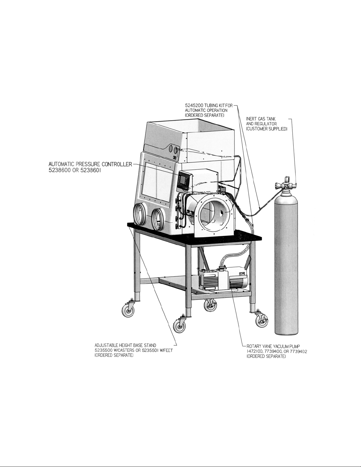
Setup
Connect the Glove Box Controller using the Labconco connections/tubing kit #5245200 (ordered
separately). Follow the separate mechanical installation instructions included with the Pressure
Controller and also listed on pages 14 through 19 of these operating instructions. When
completed, the installed system should look like the diagram below.
Labconco Operating Instructions 5242600, Rev. B 4/27/07, ECO E275 2 of 20
Page 3
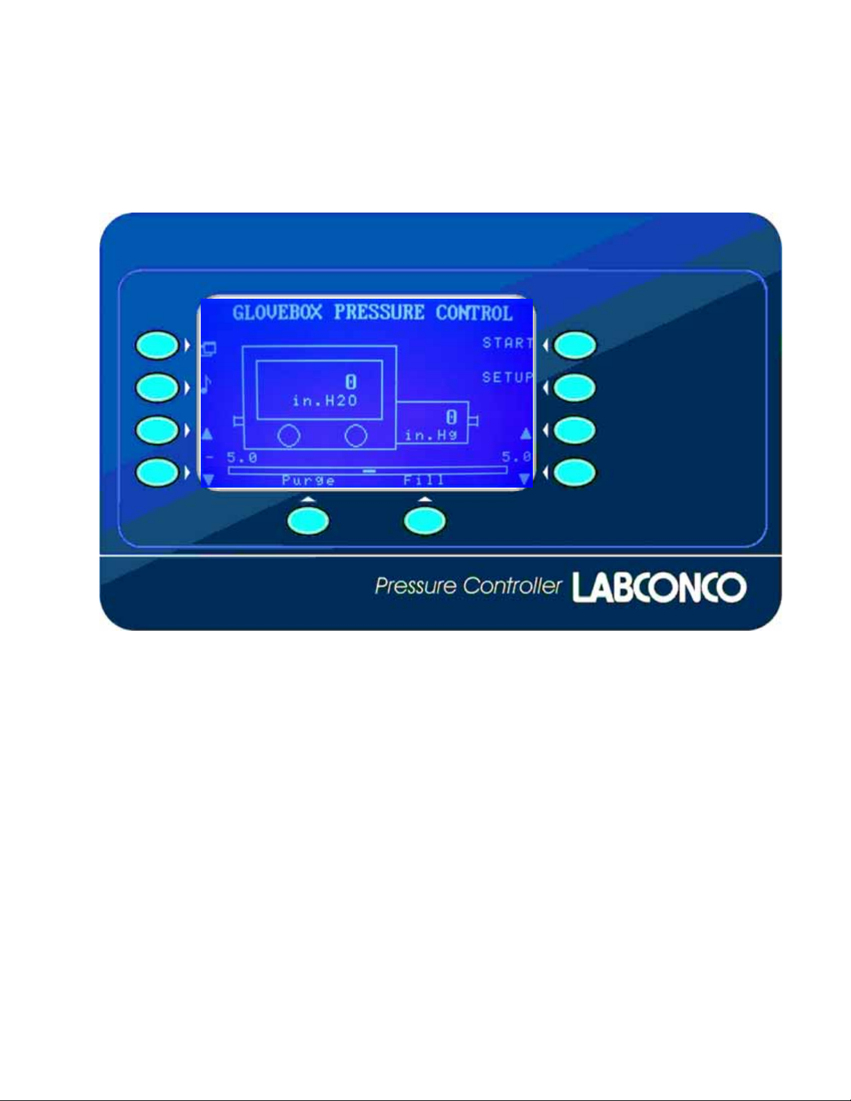
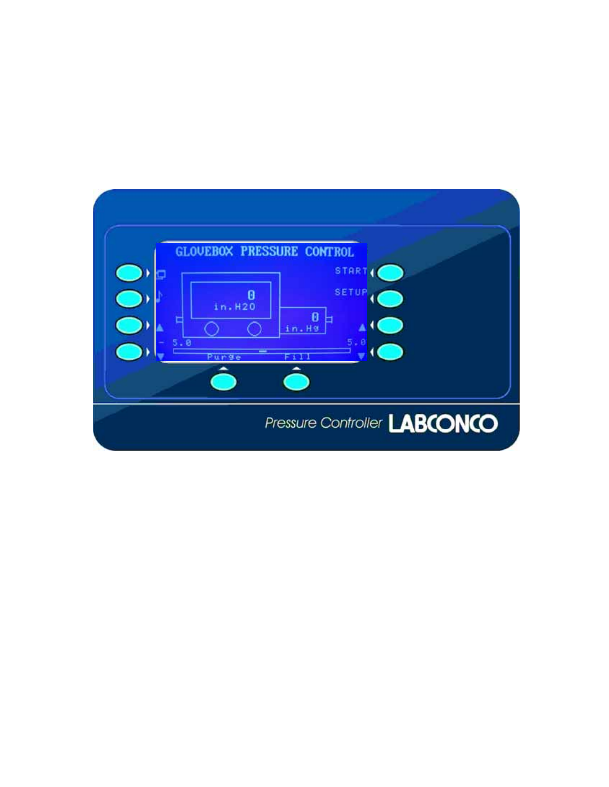
Front Panel Description
The front panel includes a large display screen and touchpad keys that are adjacent to the LCD
display. The operation of these keys will be defined by text on the display screen (LCD). Each
key may perform a different operation depending on the control mode selected.
Labconco Operating Instructions 5242600, Rev. B 4/27/07, ECO E275 3 of 20
Page 4
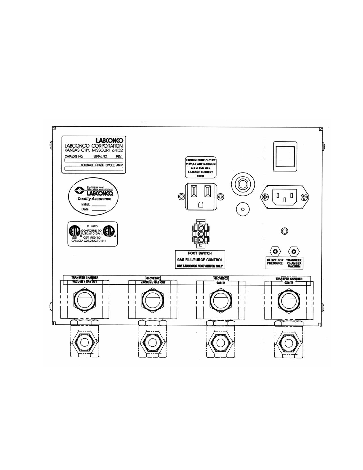
Rear Panel Description
The rear panel includes the power inlet and circuit breakers, power on/off switch, the outlet
receptacle for plugging in a vacuum pump (the receptacle varies for 115 volt and 230 volt
models), and electrical connection for the glove box pressure control footswitch. The 4 electric
solenoid valves that provide control of the glove box Main Chamber gas in/gas out, and Transfer
Chamber gas in/gas out are also located on the rear panel. See the separate mechanical
installation instructions for plumbing connections to these valves. For your convenience, the
separate mechanical and plumbing installation instructions are also located at the back of these
operating instructions on pages 14 through 19.
Labconco Operating Instructions 5242600, Rev. B 4/27/07, ECO E275 4 of 20
Page 5
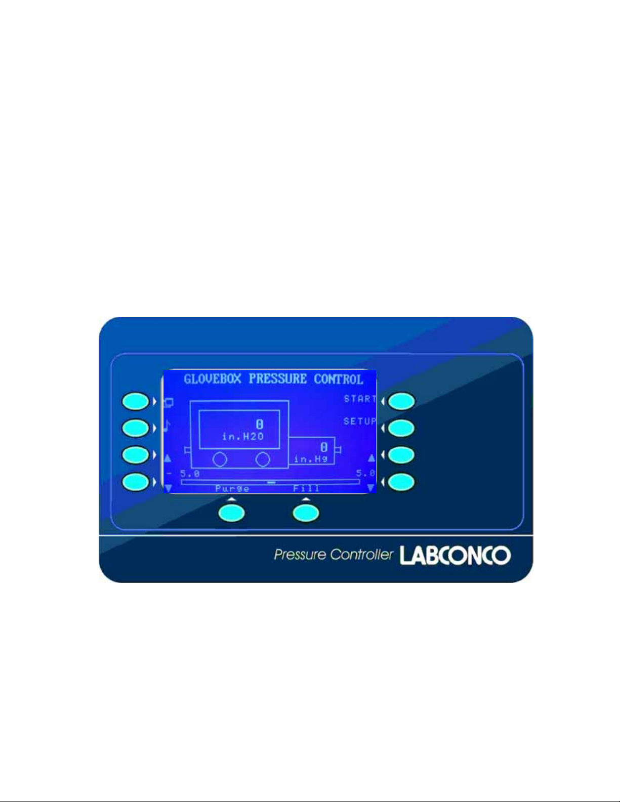
Main Modes of Operation
The Labconco Glove Box Pressure Controller display has four main screens that provide access
to the 4 modes of operation listed below. The operation modes are covered in the next sections of
this document.
1.) Glove Box Pressure Control Mode
2.) Glove Box Purge and Fill Mode
3.) Transfer Chamber Purge and Fill Mode
4.) Setup Mode
Press the Mode key at the upper-left hand corner of the display screen to switch between each of
these four operation modes. Please be aware that if one of the glove box modes is
running/started, other glove box operation modes cannot be used. For example, if the Glove Box
Pressure Control mode has started (using the start key), the menu page for the Glove Box
Purge/Fill mode cannot be used – this prevents operational control conflicts from occurring at the
same time.
Mode Key
Mute/Alarm
Increase
Lower Limit
Decrease
Lower Limit
Manual
Purge
Start/Stop
Setup
Increase
Upper Limit
Decrease
Upper Limit
Manual
Fill
Labconco Operating Instructions 5242600, Rev. B 4/27/07, ECO E275 5 of 20
Page 6
Glove Box Pressure Control – Operation Mode 1
The Pressure Control mode will allow the user to set a high pressure limit up to +5 inches water
column and a low pressure limit to -5 inches water column [+/- 12.6 mBar or +/- 1245 Pacals].
Set these high and low pressure limits with the keys adjacent to the “up” and “down” arrows on
the display. Once these limits are set, and the START key is pressed, the Pressure Controller will
automatically control the gas inlet valve, gas outlet valve, and the power to the outlet receptacle
for a vacuum pump. Pressure in the Glove Box Main Chamber will be displayed inside the glove
box icon on the display screen.
Mode Key
Mute/Alarm
Lower Limit
Decrease
Lower Limit
Increase
Manual control keys for “PURGE” and “FILL” (located along the bottom of the display) will
allow the corresponding valves to be controlled by the user to increase or decrease the pressure
inside the glove box. Note: These manual keys will not operate the valves when the pressure
is outside the limits of +/- 5 inches of water [+/- 12.6 mBar]. A three-position footswitch is
included with the Automatic Pressure Controller. The footswitch provides manual foot control of
the gas inlet and vacuum outlet valves. The pressure inside the glove box will be displayed inside
the glove box icon on the display screen.
An audio alarm will actuate if the pressure exceeds the maximum limits of +/- 5 inches of water.
An “alarm reset” key (identified by the musical icon) is provided to mute this alarm. The alarm
will reset automatically when the pressure returns within +/- 5 inches [+/- 12.6 mBar].
Manual
Purge
Start/Stop
Setup
Increase
Upper Limit
Decrease
Upper Limit
Manual
Fill
Labconco Operating Instructions 5242600, Rev. B 4/27/07, ECO E275 6 of 20
Page 7

Glove Box Purge/Fill – Operation Mode 2
The Glove Box Purge/Fill mode uses the same solenoid valves on the glove box that are used in
the Pressure Control Mode. The Pressure Control mode will be temporarily suspended while a
“Purge/Fill” command is being executed.
Mode Key
Mute/Alarm
Increase
Lower Limit
Decrease
Lower Limit
Note that this display screen looks similar to the Pressure Control mode described previously.
However, the “SETUP” key has changed to a “Cycles” key. Up to 199 cycles can be set for
automatic “Purge/Fill” of the glove box main chamber by holding the “Cycles” key. To decrease
the number cycles, press the “Cycles” key to 199 cycles and go around again until a lower cycle
quantity appears. Use this display screen to also set the low pressure level for purging and the
high pressure level for filling by adjusting the upper and lower limit keys. The Labconco
Pressure Controller allows the glove box Main Chamber pressure levels to be set to +/- 5 inches
of water column [+/- 12.6 mBar]. Once the pressure limits and number of cycles have been
selected, press the key adjacent to “Start,” and the automated purge and fill process will begin
and continue for the number of cycles selected. Each cycle number will be displayed during the
process. To cancel the automated purge and fill process, press the key adjacent to “Stop” and the
process will be stopped.
Note that when the “Glove Box Purge/Fill” mode is in operation, there are no keys available to
allow for system setup as the “Cycles” key replaced the “SETUP” key. Use the “Mode” key in
the upper left hand corner adjacent to the icon to return to the “Glove Box Pressure Control”
screen to use the “Select” mode.
Manual
Purge
Start/Stop
Cycles
Increase
Upper Limit
Decrease
Upper Limit
Manual
Fill
Labconco Operating Instructions 5242600, Rev. B 4/27/07, ECO E275 7 of 20
Page 8

Transfer Chamber Purge and Fill – Operation Mode 3
The Transfer Chamber Purge/Fill mode controls the pressure exchange inside the transfer
chamber. Pressure in the transfer chamber will be displayed inside the transfer chamber icon on
the display screen. This operation mode controls the gas inlet and gas outlet solenoid valves
connected to the transfer chamber.
Mode Key
Mute/Alarm
Increase
Lower Limit
Lower Limit
Decrease
The user may select up to 199 “Purge/Fill” cycles by adjusting the cycles increase and decrease
arrow keys. The user can select the level of pressure inside the transfer chamber during each purge
between 0 and -29.5 inches of Mercury/Hg [0 -999 mBars] by adjusting the lower limit keys. Once
the lower pressure limit and number of cycles have been selected, press the key adjacent to “Start,”
and the automated purge and fill process will begin and continue for the number of cycles selected.
Each cycle will be displayed during the process. To cancel the automated purge and fill process,
press the key adjacent to “Stop” and the process will be stopped.
Manual
Purge
Start/Stop
Setup
Increase
Cycles
Decrease
Cycles
Manual
Fill
Labconco Operating Instructions 5242600, Rev. B 4/27/07, ECO E275 8 of 20
Page 9

Setup Menu – Operation Mode 4
Pressing the key opposite the word “Setup,” allows access to the setup operation mode. In the
setup mode, the user may select their preferred units of pressure that are displayed, restore
settings back to the default state, or calibrate the pressure sensors. The keys adjacent to the up
and down arrows on the lower right of the display are used to select one of the three options.
After toggling up or down, push the NEXT key to select the option.
Select
Key Up
Select
Key Down
Back to
Previous
Screen
Next
Screen
Option 1
Units of Measure: If this option is selected, the key adjacent to “Next” is used to select pressure
units of inches of water/inches of mercury or mBar.
Helpful conversions are as follows:
1 mBar = .39 inches of water column
1 mbar = .0292 inches of mercury
1 inch of water = 2.52 mBar = .0737 inches of mercury
1 inch of mercury = 34.25 mBar
All pressures are measured with respect to atmosphere pressure.
Option 2
Restore Defaults: The restore defaults option restores all control settings to the initial
programmed settings which are listed in the back of these operating instructions.
Labconco Operating Instructions 5242600, Rev. B 4/27/07, ECO E275 9 of 20
Page 10

Option 3
Calibration: The pressure sensors inside the controller can be calibrated using atmospheric
pressure (single point calibration) or atmospheric pressure and a specific pressure level (two
point calibration). Two point calibration provides increased accuracy; however, Labconco
recommends that only the single point calibration be used because it does not require a calibrated
pressure measurement standard. When “Calibration” is selected, the display screen below
appears. The keys adjacent to the up and down arrows on the lower right of the display are used
to select one of the options. After toggling up or down, push the NEXT key to select the option.
Select
Key Up
Select
Key Down
Back to
Previous
Screen
Next
Screen
Note: If option 2 or 3 above is selected, an accurate, traceable pressure measuring device must
be connected to the Labconco pressure sensors. Consult Labconco for further instructions for this
type of calibration.
Option 1 above is normally selected. Both doors must be open so atmospheric pressure is
available to both the glove box main chamber and transfer chamber. Select the NEXT key to
advance the screen to sensor offset for Option 1. The display screen changes are shown on the
next page for Option 1.
Labconco Operating Instructions 5242600, Rev. B 4/27/07, ECO E275 10 of 20
Page 11

Back to
Previous
Screen
Yes, All
Doors
Open
To calibrate the pressure sensors for both chambers, the doors must be open so that atmospheric
pressure is present at both sensors. This is the “zero point” for both sensors. Both pressure
gauges on the glove box will also read “zero.”
With both doors open, press the key adjacent to “Yes.” Once this is done, the following display
screen on the next page appears:
Labconco Operating Instructions 5242600, Rev. B 4/27/07, ECO E275 11 of 20
Page 12

Main Glove
Box Chamber
Select Key
This display screen confirms that the doors are open and the sensors are ready for auto-zeroing.
First, select the Main Glove Box Chamber key (Box) and wait for complete calibration to zero
pressure. Next, select the Transfer Chamber key (CH) and wait for complete calibration to zero
pressure. Once the key adjacent to “Save” is pressed, the new sensor offset valves for both
chambers are stored, and this pressure becomes the zero point for both chambers. Select the
back key two times when calibration is complete to return to the three main modes of operation.
Pressure Control Foot Switch (Labconco #5243600)
Back to
Previous
Screen
Transfer
Chamber
Select Key
Save
Zero
Point
The three position (increase gas/fill, off, purge/decrease gas) foot switch should be plugged into
the back panel of the Labconco Pressure Controller. The Foot Switch has the same effect as
pressing the Purge and Fill keys on the display panel. The action of the Foot Switch depends on
what mode of operation is shown on the display. If the transfer chamber screen is shown on the
display, the Foot Switch will control the Transfer Chamber gas in and gas out valves. If the
display shows the Glove Box Pressure Control or the Glove Box Purge/Fill, the Foot Switch will
control the Glove Box Main Chamber gas in and gas out valves. The foot switch will not work
when the pressure/vacuum inside has exceeded the user preset limits shown on the display.
Labconco Operating Instructions 5242600, Rev. B 4/27/07, ECO E275 12 of 20
Page 13

Labconco Glove Box Controller Specifications
Glove Box
Operating Range Default Settings
Pressure Control
Pressure Control Limits -5 inches of water column to
+5 inches of water column;
+/- 5 inches of water column;
[+/- 12.6 mBar].
[+/- 12.6 mBar]
Manual Control Available Purge (Gas out);
Fill (Gas in)
Audio Alarm level Whenever pressure
outside limits
Glove Box Purge/Fill
Purge/Fill Pressure Limit +/- 5 inches of water column;
Manual Control Available Purge (Gas out);
+/- 5 inches of water column;
[+/- 12.6 mBar].
[+/- 12.6 mBar].
Fill (Gas in)
Number of Purge/Fill
0 to 199 1
Cycles
Audio Alarm level Whenever pressure
outside limits
Transfer Chamber
Purge/Fill
Purge Pressure Limit -29.5 inches of Mercury/Hg
[-999 mBars]
Fill Pressure Limit 0 inches of Mercury/Hg
[0 mBars](atmosphere)
Number of Purge/Fill
0 to 199 1
-29.5 inches of Mercury/Hg
[-999 mBars]
0 inches of Mercury/Hg
[0 mBars](atmosphere)
Cycles
Audio Alarm level -29.5 inches of Mercury/Hg
[-999 mBars]
Whenever pressure/vacuum
outside limits
Labconco Operating Instructions 5242600, Rev. B 4/27/07, ECO E275 13 of 20
Page 14

Mechanical and Plumbing Installation Instructions
NOTE: The Pressure Controller is configured to mount on the Glove Box. If your use
is better served in the benchtop configuration, a benchtop mounting bracket (#5239100)
can be ordered separately.
Glove Box Mounting:
Installation
1. Remove the two acorn nuts and lock washers as shown in Detail A insert. Place the
Pressure Controller assembly over the studs as shown and secure with the previously
removed nuts and washers.
2. See the plumbing installation section for the Glove Box mounting.
Labconco Operating Instructions 5242600, Rev. B 4/27/07, ECO E275 14 of 20
Page 15

Benchtop Mounting:
Installation (Detail B)
1. Disconnect the power source from the Pressure Controller.
2. Remove the Glove Box mounting bracket and attach the Benchtop mounting bracket.
3. Remove the eight screws that attach the Pressure Controller Cover to the Pressure
Controller. Lift the cover straight up and set aside.
4. Remove the six nuts securing the Pressure Controller to the Glove Box bracket.
5. Next, place the Pressure Controller on top of the Benchtop Mounting Bracket, attach
with the six nuts previously removed securing the Pressure Controller to the Benchtop
Mounting Bracket.
6. See plumbing installation section for benchtop mounting.
Labconco Operating Instructions 5242600, Rev. B 4/27/07, ECO E275 15 of 20
Page 16

Plumbing:
Always install the polyvinyl tubing to the solenoid valves on the pressure
controller before placing at the benchtop location. Refer to Detail C for valve
inlet and outlet order.
Glove Box Installation
1. The Pressure Controller has been pre-plumbed for installation in the Glove Box
configuration.
2. Route the tubing to the Glove Box and Transfer Chamber as shown in Detail C. Note:
Tube routing maybe dependent upon your application. Always insure that the
tubing is routed to the correct solenoid valve on the Pressure Controller as
stated on the back of the unit.
3. See Detail D for proper tube installation to the valves on the Glove Box and Transfer
Chamber.
Labconco Operating Instructions 5242600, Rev. B 4/27/07, ECO E275 16 of 20
Page 17

Benchtop Installation: With the Pressure Controller temporary located at the benchtop location
proceed as follows.
1. Measure the distance between the solenoid valves of the Pressure Controller and the
valves on the glove box. Cut the 3/16 ID tubing (the larger of the tubing in your kit)
to the measured lengths.
2. The solenoid valves are embossed with IN or OUT port on the body of the valve, to
indicate the direction of flow. Install the cut lengths of the tubing to the correct port
of the solenoid valve as shown in Detail C.
3. Secure the tubes to the underside of the mounting bracket using the “C” clips
provided and place at the approximate locations shown in Detail C.
4. Route the tubing to the Glove Box and Transfer Chamber as shown in Detail C. Note:
Tube routing maybe dependent upon your application. Always insure that the
tubing is routed to the correct solenoid valve on the Pressure Controller as
stated on the back of the unit.
5. See Detail D for proper tube installation to the valves on the Glove Box and Transfer
Chamber.
Sensor Integration:
The Pressure Controller must be integrated to the glove box. This connection
allows your Pressure Controller to monitor the condition of the glove box
chamber and transfer chamber.
TUBE INSERT
TUBE FERRULE
BACK FERRULE
NUT
TUBING
Installation
1. Your kit comes with extra length of polyvinyl tubing so you can integrate the
Pressure Controller with the glove box. This integration requires you to splice into the
existing tubing of your Glove Box, install a bulkhead fitting and new tubing.
Labconco Operating Instructions 5242600, Rev. B 4/27/07, ECO E275 17 of 20
Page 18

2. Bulkhead Fitting
a. Locate the brass mini bulkhead fitting in your kit and install the fitting at the
opening provided on the back wall of the glove box wrapper (see Detail E).
3. Glove Box Pressure
a. Locate the line that comes from the pressure gauge (see Detail E ) to the
fitting installed at the top of your glove box. This gauge is labeled on the front
panel and is the one on your right when looking at the back of the front panel
(see Detail E). This line is also a contaminated line on existing glove boxes
and the appropriate precautions should be taken.
b. Make a cut in the line about halfway between the gauge and the fitting. Join
the cut lengths together with the brass tee that came with you kit.
c. Measure and cut a length of the 3/32 ID polyvinyl tubing (the smaller of the
tubing) and connect the spliced tee to the mini bulkhead fitting on the back of
the Glove Box wrapper.
d. Again, measure and cut a length of the same tubing and connect it between the
mini bulkhead fitting on the glove box wrapper and the port labeled “Glove
Box Pressure” on the back of the Pressure Controller (see Detail E).
4. Transfer Chamber Vacuum
a. Locate the existing line that comes from the back of your glove box wrapper
to the transfer chamber fitting (see Detail E).
b. Make a cut in the line at a point near or within 12 inches of the transfer
chamber fitting and join the line together with a brass tee that came with your
kit.
c. Measure and cut a length of the 3/32 ID polyvinyl tubing (the smaller of the
tubing) and connect the spliced tee to the port labeled “Transfer Chamber
Vacuum” on the back of he Pressure Controller (see Detail E).
Labconco Operating Instructions 5242600, Rev. B 4/27/07, ECO E275 18 of 20
Page 19

Parts List:
Part No. Description
1 5239800 Pressure Controller 115V
1 5239801 Pressure Controller 230V
2 5239100 Benchtop bracket (ordered separately)
3 5237000 Glove Box bracket
4 1539500 3/16 ID Polyvinyl Tubing
5 1409900 Tube Inserts
6 1407400 Brass Tee
7 1554304 3/32 ID Polyvinyl Tubing
8 1337100 Power Cord – 115V
8 1338000 Power Cord – 230V
9 1449400 Mini Bulkhead Fitting
10 1937700 “C” Clips
Labconco Operating Instructions 5242600, Rev. B 4/27/07, ECO E275 19 of 20
Page 20

Copyright © 2007 Labconco Corporation. Al l right s reser ved .
The information contained in this manual and the accompanying products are copyrighted and all rights reserved by
Labconco Corporation. Labconco Corporation reserves the right to make periodic design changes without
obligation to notify any person or entity of such change.
Warranty
Labconco provides a warranty on all parts and factory workmanship. The warranty includes areas of
defective material and workmanship, provided such defect results from normal and proper use of the
equipment.
The warranty for all Labconco products will expire one year from date of installation or two years from
date of shipment from Labconco, whichever is sooner, except the following;
• Purifier® Delta® Series Biological Safety Cabinets and PuriCare® Lab Animal Research
Stations carry a three-year warranty from date of installation or four years from date of shipment
from Labconco, whichever is sooner.
• SteamScrubber® & FlaskScrubber® Glassware Washers carry a two-year warranty from date of
installation or three years from date of shipment from Labconco, whichever is sooner.
• Blood Drawing Chairs carry a ten year warranty.
• Carts carry a lifetime warranty.
• Glassware is not warranted from breakage when dropped or mi shan dl ed.
This limited warranty covers parts and labor, but not transportation and insurance charges. In the event of
a warranty claim, contact Labconco Corporation or the dealer who sold you the product. If the cause is
determined to be a manufacturing fault, the dealer or Labconco Corporation will repair or replace all
defective parts to restore the unit to operation. Under no circumstances shall Labconco Corporation be
liable for indirect, consequential, or special damages of any kind. This statement may be altered by a
specific published amendment. No individual has authorization to alter the provisions of this warranty
policy or its amendments. Lamps and filters are not covered by this warranty. Damage due to corrosion or
accidental breakage is not covered.
Returned or Damaged Goods
Do not return goods without the prior authorization from Labconco. Unauthorized returns will not be accepted. If
your shipment was damaged in transit, you must file a claim directly with the freight carrier. Labconco Corporation
and its dealers are not responsible for shipping dam ages.
The United States Interstate Commerce Commission rules require that claims be filed with the delivery carrier
within fifteen (15) days of delivery.
Limitation of Liability
The disposal and/or emission of substances used in connection with this equipment may be governed by various
federal, state, or local regulations. All users of this equipment are required to become familiar with any regulations
that apply in the user’s area concerning the dumping of waste materials in or upon water, land, or air and to comply
with such regulations. Labconco Corporation is held harmless with respect to user’s compliance with such
regulations.
Contacting Labconco Corporation
If you have questions that are not addressed in this manual, or if you need technical assistance, contact Labconco’s
Customer Service Department or Labconco’s Product Service Department at 1-800-821-5525 or 1-816-333-8811,
between the hours of 7:00 a.m. and 6:00 p.m., Central Standard Time.
Labconco Operating Instructions 5242600, Rev. B 4/27/07, ECO E275 20 of 20
 Loading...