

Labconco Paramount 69632, Paramount 69633, Paramount 69634, Paramount 69635, Paramount 69636 User Manual
Page 1

User’s Manual
Paramount®Ductless Enclosures
Models
69632 Series, 2' Widths
69633 Series, 3' Widths
69634 Series, 4' Widths
69635 Series, 5' Widths
69636 Series, 6' Widths
To receive important product updates,
complete your product registration card
online at register.labconco.com
Labconco Corporation
8811 Prospect Avenue
Kansas City, MO 64132-2696
800-821-5525, 816-333-8811
FAX 816-363-0130
E-MAIL labconco@labconco.com
HOME PAGE www.labconco.com
Please read the User’s Manual before operating the equipment.
Page 2

Copyright © 2008, 2009, 2010 Labconco Corporation. All rights reserved.
The information contained in this manual and the accompanying products are copyrighted and all rights
reserved by Labconco Corporation. Labconco Corporation reserves the right to make periodic design
changes without obligation to notify any person or entity of such change.
Warranty
Labconco provides a warranty on all parts and factory workmanship. The warranty includes areas
of defective material and workmanship, provided such defect results from normal and proper use of
the equipment.
The warranty for all Labconco products will expire one year from date of installation or two years
from date of shipment from Labconco, whichever is sooner, except the following;
• Purifier® Logic® Biological Safety Cabinets and PuriCare® Lab Animal Research
Stations carry a three-year warranty from date of installation or four years from date of
shipment from Labconco, whichever is sooner.
• SteamScrubber® & FlaskScrubber® Glassware Washers carry a two-year warranty from
date of installation or three years from date of shipment from Labconco, whichever is
sooner.
• Blood Drawing Chairs carry a ten year warranty.
• Carts carry a lifetime warranty.
• Glassware is not warranted from breakage when dropped or mishandled.
This limited warranty covers parts and labor, but not transportation and insurance charges. In the
event of a warranty claim, contact Labconco Corporation or the dealer who sold you the product. If
the cause is determined to be a manufacturing fault, the dealer or Labconco Corporation will repair
or replace all defective parts to restore the unit to operation. Under no circumstances shall
Labconco Corporation be liable for indirect, consequential, or special damages of any kind. This
statement may be altered by a specific published amendment. No individual has authorization to
alter the provisions of this warranty policy or its amendments. Lamps and filters are not covered by
this warranty. Damage due to corrosion or accidental breakage is not covered.
Returned or Damaged Goods
Do not return goods without the prior authorization from Labconco. Unauthorized returns will not be
accepted. If your shipment was damaged in transit, you must file a claim directly with the freight
carrier. Labconco Corporation and its dealers are not responsible for shipping damages.
The United States Interstate Commerce Commission rules require that claims be filed with the delivery
carrier within fifteen (15) days of delivery.
Limitation of Liability
The disposal and/or emission of substances used in connection with this equipment may be governed by
various federal, state, or local regulations. All users of this equipment are required to become familiar
with any regulations that apply in the user’s area concerning the dumping of waste materials in or upon
water, land, or air and to comply with such regulations. Labconco Corporation is held harmless with
respect to user’s compliance with such regulations.
Contacting Labconco Corporation
If you have questions that are not addressed in this manual, or if you need technical assistance, contact
Labconco’s Customer Service Department or Labconco’s Product Service Department at 1-800-8215525 or 1-816-333-8811, between the hours of 7:00 a.m. and 6:00 p.m., Central Standard Time.
Part #6968600, Rev. D
ECO G099
Page 3

T
AABBLLEE
T
CHAPTER 1: INTRODUCTION 1
CHAPTER 2: PREREQUISITES 3
Support and Stability Requirements 3
Location and Air Current Requirements 4
Exhaust and Blower Requirements 4
Electrical Requirements 6
Space Requirements 6
CHAPTER 3: GETTING STARTED 7
Unpacking the Enclosure 8
Set Up the Ductless Enclosure on a Supporting Structure and
Work Surface 8
Install Carbon Filters and/or HEPA Filters 11
Connect the Electrical Supply 12
Set Filter Life and Filter Check Timers 12
Initial Safety-First™ Vapor Sensor Warm Up Period 13
Reset or Change the Airflow Face Velocity (If Necessary) 13
Validate the Enclosure 14
Seal the Enclosure to the Work Surface 14
Connecting to the Exhaust System (If Applicable) 14
CHAPTER 4: PERFORMANCE FEATURES AND SAFETY
High Performance Containment 17
Safety-First™ Vapor Sensor 18
Smart-Flow™ Airflow Monitor 19
Quiet, Energy-Efficient ECM Impeller 19
Audible/Visual Alarms 19
Large Control Panel LCD Display 19
Ergonomic Sloped Front 20
Convenient Filter Replacement 20
Durable Construction 20
Fluorescent Light with Electronic Ballast 20
Utility Iris Ports 20
O
O
PRECAUTIONS 15
FF
C
C
OONNTTEENNTTSS
Page 4

Maximum Visibility 21
Simple Electrical Connection 21
Safety Precautions 21
Misapplications that Could Result in a Hazardous Situation 24
CHAPTER 5: USING THE DUCTLESS ENCLOSURE 25
Information Center 25
Status Area 26
Operating the Pivoting Sash 26
Starting the Ductless Enclosure 26
The Paramount Touchpad 27
All Program Screens 28
Calibration Program Screens 31
Diagnostic Program Screens 32
User Selectable Features 33
Clock Timer Operation 33
Interval Timer Operation 33
Elapsed Timer Operation 33
Light Lamp Timer and Blower Timer 34
Blower Operation 34
Enclosure Set Up 34
Units of Measure 34
Security Lock 34
Filter Setup Display Options 35
Restoring Software Default Settings 35
Calibration 35
Diagnostic Test Operation 35
If a Check Airflow Activates 36
Resetting the Airflow Alert System 36
Working in the Paramount Ductless Enclosure 36
CHAPTER 6: MAINTAINING THE DUCTLESS ENCLOSURE 38
Routine Maintenance Schedule 38
Determination of When to Replace Carbon Filters 39
Determination of When to Replace HEPA Filters 41
Install Carbon Filters and/or HEPA Filters 42
Set Filter Life and Filter Check Timers 42
HEPA Filter Leak Test 42
Change the Airflow Face Velocity (If Necessary) 44
Initial Certification 44
Re-Certification 44
Fluorescent Light Replacement 45
Motorized Impeller Replacement 47
Main Control Board Replacement 48
Organic Sensor Board Replacement 49
Page 5

CHAPTER 7: ACCESSORIZING THE DUCTLESS
ENCLOSURE 50
Filters 50
Work Surfaces 51
Work Surface with Deck Mounted Valves, Gooseneck,
and Cupsink 52
Base Stands, Accessory Shelves, Seismic Supports and
Hydraulic Lift Base Stands 53
Storage Cabinets 54
Exhaust Transitions 55
Remote Blowers 56
Exhaust Dampers 57
Utility Shelf Kits and Holders 57
Syringe Pump Kit and Detector Tubes 57
Sash Closures 58
CHAPTER 8: TROUBLESHOOTING 59
APPENDIX A: REPLACEMENT PARTS 62
APPENDIX B: PARAMOUNT DIMENSIONS 65
APPENDIX C: SPECIFICATIONS 66
APPENDIX D: QUICK CHART 67
APPENDIX E: ESTIMATED FILTER LIFE CALCULATION 68
APPENDIX F: FILTRATION EFFICIENCY TEST RESULTS 70
Acetone 71
Ethyl Alcohol 72
Isopropyl Alcohol 73
Toluene 74
Hydrochloric Acid 75
DECLARATION OF CONFORMITY 76
Page 6

CChhaapptteerr 11::
IInnttrroodduuccttiioonn
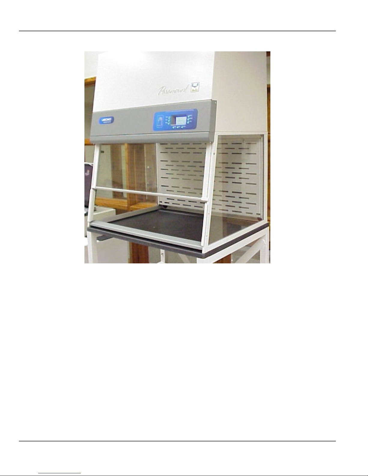
Congratulations on the purchase of a Labconco Paramount
Enclosure, commonly called a ductless fume hood. Unlike traditional fume
hoods, the Paramount Ductless Enclosure is considered green as it conserves
energy because it requires no ducting. The Paramount Ductless Enclosure
is a self-contained work station that protects the operator from specified
vapors and/or particulates released in the work area, through the use of
carbon filters and/or HEPA filters. Typical organic solvents, formaldehyde,
acid gases, ammonia, amines, particulates, and powders are contained inside
the enclosure to protect the operator and then filtered. Purified air is drawn
from the filters and returned to the room. Vapors are adsorbed on activated
carbon filters or impregnated carbon filters and particulates/powders are
filtered by the HEPA filter.
Each Paramount Ductless Enclosure includes the Safety-First™ Vapor
Sensor that detects filter saturation and alerts the operator to replace the
filters. The early warning provided by the Safety-First Vapor Sensor
provides the user ample time (5-10% remaining filter life) to complete work
in process before changing the filters. The Safety-First Vapor Sensor
includes a primary and secondary sensor for redundant monitoring and the
sensor detects typical organic solvents, smoke particulates, ammonia gases,
formaldehyde gases, and hydrogen sulfide gases. The Paramount Ductless
Enclosure is the result of Labconco’s years of experience in the design and
manufacture of fume hoods and ductless hoods.
The Paramount Ductless Enclosure offers many unique features to enhance
safety, performance, and ergonomics. Safety is illustrated with the SafetyFirst Vapor Sensor. Performance and Safety are illustrated with validated
containment and patented aerodynamic features (U.S. Patent No. 6,461,233).
Ergonomics is illustrated with the patented inclined design (U.S. Patent No.
D538,941). To take full advantage of all features, please acquaint yourself
with this manual and keep it handy for future reference. If you are unfamiliar
with how ductless enclosures operate, please review Chapter 4: Performance
Features and Safety Precautions, before you begin working.
®
Ductless
Product Service 1-800-522-7658
1
Page 7

Chapter 1: Introduction
Even if you are an experienced ductless enclosure user, please review
Chapter 5: Using the Ductless Enclosure; it describes the Paramount
Ductless Enclosure features so that you can use it efficiently and effortlessly.
The Paramount Ductless Enclosure ships without any filters. Chapter 3:
Getting Started and Chapter 6: Maintaining the Ductless Enclosure, must
be followed to properly select and install filters.
This manual and other technical information is available in PDF format
at our website: www.labconco.com.
2
Product Service 1-800-522-7658
Page 8

CChhaapptteerr 22::
PPrreerreeqquuiissiitteess
Before you install the Paramount Ductless Enclosure, you need to prepare
your site for installation. A dedicated source of electrical power should be
located near the installation site to power the ductless enclosure and other
apparatus. Additionally, the enclosure should be strategically placed in the
lab to provide efficient workflow.
Carefully read this chapter to learn the requirements for your installation site:
• The support and stability requirements.
• The location and air current requirements.
• The exhaust and blower requirements.
• The electrical power requirements.
• Space requirements.
Refer to Appendix B: Dimensions for complete enclosure dimensions.
Refer to Appendix C: Specifications for complete enclosure electrical and
environmental conditions, specifications and requirements.
Support and Stability Requirements
At a minimum, the supporting structure usually consists of a base cabinet or
stand and a chemically resistant work surface. Please consider the following:
• Work surfaces should be of a thick rigid material that remains stable.
• A bench that is rigidly mounted to the floor or fixed to the wall may
be appropriate.
• Tubular stands or mobile benches with locking casters may be
appropriate.
Product Service 1-800-522-7658
3
Page 9

Chapter 2: Prerequisites
Location and Air Current Requirements
The Paramount Ductless Enclosures have been designed to contain hazards
by negating typical cross drafts and turbulence within the opening. However,
it is recommended that the enclosure be placed in an area to avoid:
• High traffic areas where walking might cause an air disturbance or be a
nuisance.
• Overhead or wall HVAC diffusers, fans, radiators or other lab equipment
producing air currents.
• Near doorways or windows that may be opened.
Exhaust and Blower Requirements
The Paramount Ductless Enclosure uses a green, 95% energy efficient,
electronically-commutated motorized (ECM) impeller to draw room air past
the operator and through the enclosure (see Appendix D for power usage by
model). This contaminated air is passed through filters and exhausted out the
top of the enclosure. The filtered exhaust air is normally recirculated into the
laboratory or may be exhausted outside with the addition of the Canopy
Exhaust Connection and remote blower listed in Chapter 7. Contact
Labconco for blower sizing assistance for exhausting to the outside.
Electrical connections are covered in Chapter 2 for this configuration.
Data for the enclosure’s exhaust volume, noise pressure and face velocity are
listed on the next page in chart form for each Paramount Ductless Enclosure
model at face velocities of 60, 80, and 100 fpm. All models are shipped to
operate at 75-80 fpm, but can be reset by the Safety Officer or certification
technician through a password protected menu.
Important Note: If the enclosure is connected directly to a house exhaust system,
an adjustable damper (or valve) must be installed to control the airflow properly.
This is equally important when a house exhaust system is controlling multiple
ductless enclosures. See Chapter 7 for information on accessories.
4
Product Service 1-800-522-7658
Page 10
Chapter 2: Prerequisites
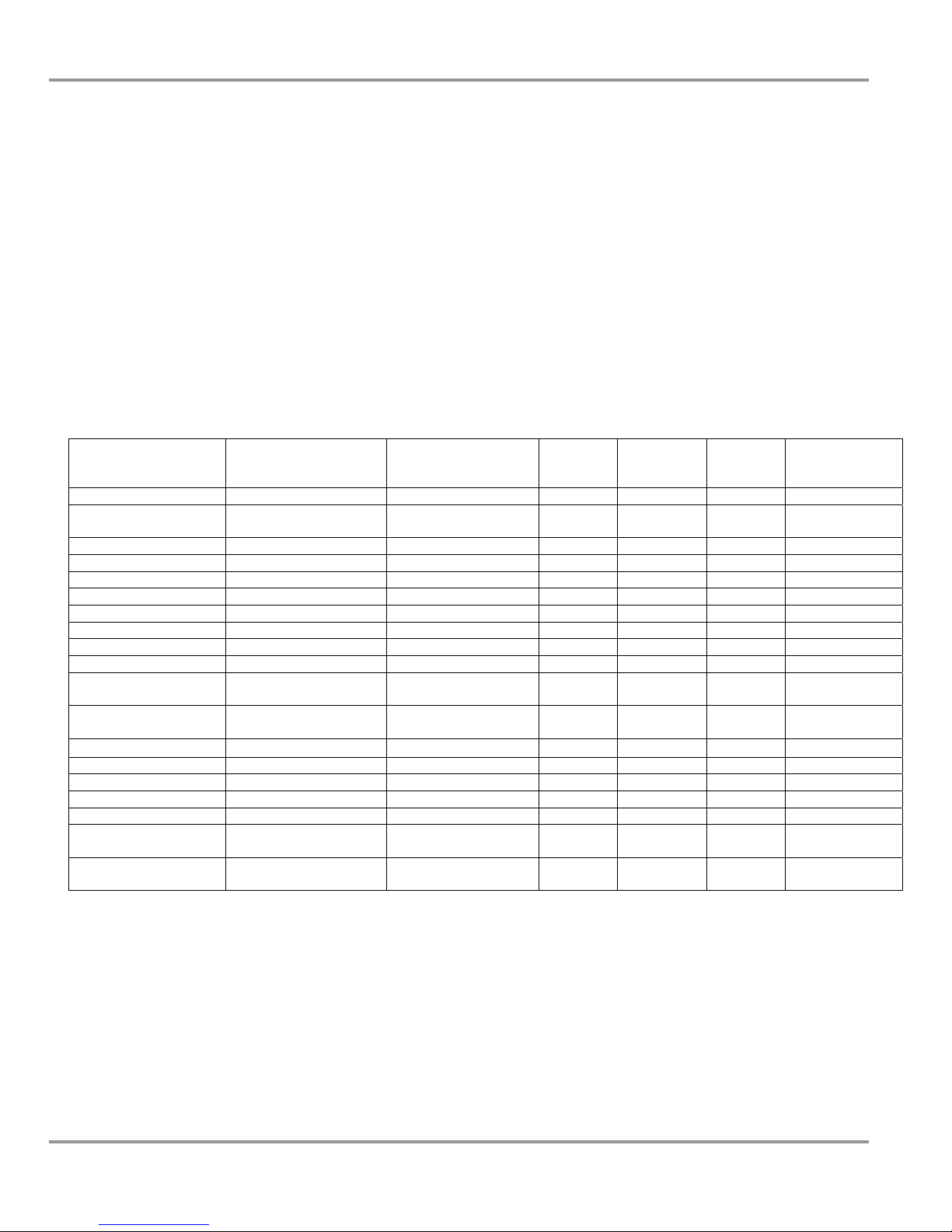
Model No. Voltage
6963200 100-115V 2' 22.7" 9.4" 29" 43.7"
6963220 208-230V 2' 22.7" 9.4" 29" 43.7”
6963300 100-115V 3' 22.7" 9.4" 29" 43.7"
6963301 100-115V 3' 32" 12" 29" 53"
6963302 100-115V 3' 32" x 360° 12" 29" 53"
6963320 208-230V 3' 22.7" 9.4" 29" 43.7"
6963321 208-230V 3' 32" 12" 29" 53"
6963322 208-230V 3' 32" x 360° 12" 29" 53"
6963400 100-115V 4' 22.7" 9.4" 29" 43.7"
6963401 100-115V 4' 32" 12" 29" 53"
6963402 100-115V 4' 32" x 360° 12" 29" 53"
6963403 100-115V 4' 35" 12" 35.5" 56"
6963420 208-230V 4' 22.7" 9.4" 29" 43.7"
6963421 208-230V 4' 32" 12" 29" 53"
6963422 208-230V 4' 32" x 360° 12" 29" 53"
6963423 208-230V 4' 35" 12" 35.5" 56"
6963501 100-115V 5' 32" 9.4" 29" 53"
6963503 100-115V 5' 35" 9.4" 35.5" 56"
6963521 208-230V 5' 32" 9.4" 29" 53"
6963523 208-230V 5' 35" 9.4" 35.5" 56"
6963601 100-115V 6' 32" 12" 29" 53"
6963603 100-115V 6' 35" 12" 35.5" 56"
6963621 208-230V 6' 32" 12" 29" 53"
6963623 208-230V 6' 35" 12" 35.5" 56"
Enclosure
Width
Internal
Working
Height
Sash
Opening
Exterior
Depth
Exterior
Height
Face
Velocity
(fpm)
60
80
100
60
80
100
60
80
100
60
80
100
60
80
100
60
80
100
60
80
100
60
80
100
60
80
100
60
80
100
60
80
100
60
80
100
60
80
100
60
80
100
60
80
100
60
80
100
60
80
100
60
80
100
60
80
100
60
80
100
60
80
100
60
80
100
60
80
100
60
80
100
Airflow
Exhaust
Volume
(CFM)
85
115
145
85
115
145
130
175
220
170
230
285
170
230
285
130
175
220
170
230
285
170
230
285
175
235
295
230
305
380
230
305
380
230
305
380
175
235
295
230
305
380
230
305
380
230
305
380
220
295
370
220
295
370
220
295
370
220
295
370
350
465
580
350
465
580
350
465
580
350
465
580
Noise
Pressure
(dbA)
50
54
59
50
54
59
46
52
56
52
57
62
52
57
62
46
52
56
52
57
62
52
57
62
53
57
62
57
62
67
57
62
67
59
62
67
53
57
62
57
62
67
57
62
67
59
62
67
57
62
67
57
62
67
57
62
67
57
62
67
57
61
66
57
61
66
57
61
66
57
61
66
Product Service 1-800-522-7658
5
Page 11

Chapter 2: Prerequisites
Electrical Requirements
Standard duplex electrical receptacles should be nearby for connecting the
Paramount Ductless Enclosure and other equipment. The enclosures include iris
pass-through ports to allow electrical cords through the back of the enclosure
without leaving a large hole for contaminants to escape. (See Appendix C for
amperage.)
There is no provision for controlling a remote blower for exhausting air from the
Paramount Ductless Enclosure. If remote blower control is required, a qualified
electrician may connect a wall-mounted power outlet switch receptacle nearby so
that the switch controls both the remote blower and the outlet. The power cord
for the Paramount is then plugged into this outlet.
Space Requirements
The dimensions for the different models are shown in the chart in Chapter 2 and
detailed in Appendix B: Dimensions. To convert inches to millimeters, multiply
by 25.4.
6
Product Service 1-800-522-7658
Page 12

CChhaapptteerr 33::
GGeettttiinngg SSttaarrtteedd
Now that the site for your Paramount Ductless Enclosure is properly
prepared, you are ready to unpack, inspect, install, and validate your system.
Read this chapter to learn how to:
• Unpack and move the enclosure.
• Set up the enclosure with the proper supporting structure and work
surface.
• Install carbon filters and/or HEPA filters.
• Connect the electrical supply.
• Set Filter Life and Filter Check Timers.
• Reset or change the face velocity, if necessary.
• Validate the enclosure.
• Seal the enclosure to the work surface.
• If applicable, connect to an exhaust system.
Depending upon which model you are installing, you may need common
mechanical and electrical installation tools in addition to 5/16", 3/8", 7/16",
and 1/2" wrenches, ratchets, sockets, a nut driver set, a flat-blade screwdriver,
a Phillips screwdriver, and a carpenter level to complete the instructions in
the chapter.
Note: Each enclosure model weighs between 125 to 350 lbs. (55 to 152 kg).
The shipping container allows for lifting with a mechanical lift truck or
floor jack. If you must lift the enclosure manually, follow safe-lifting
guidelines. Do not lift by the front air foil.
Product Service 1-800-522-7658
7
Page 13

Chapter 3: Getting Started
Unpacking the Enclosure
We recommend that you do not remove the enclosure from its shipping
container until it is ready to be placed into its final location. Move the unit
by placing a flat, low dolly under the shipping skid, or by using a floor jack.
Carefully remove the shrink-wrap or carton on the enclosure and inspect it
for damage that may have occurred in transit. If damaged, notify the delivery
carrier immediately and retain the entire shipment intact for inspection by the
carrier.
Note: The United States Interstate Commerce Commission rules require that
claims be filed with the delivery carrier within fifteen (15) days of delivery.
Note: Do not return goods without the prior authorization of Labconco.
Unauthorized returns will not be accepted.
Note: If the enclosure was damaged in transit, you must file a claim directly
with the freight carrier. Labconco Corporation and its dealers are not
responsible for shipping damages.
Do not discard the packing material until you have checked all of the
components and tested the enclosure.
Do not move the enclosure by tilting it onto a hand truck.
Set Up the Ductless Enclosure on a Supporting
Structure and Work Surface
When installing the enclosure onto a chemical-resistant work surface or
benchtop, ensure that the structure can safely support the combined weight of
the enclosure and any related equipment. See Chapter 7: Accessorizing the
Paramount Ductless Enclosure for appropriate work surfaces, stands,
and cabinets. The work surface should be at least as wide as the enclosure
to properly support it. The front of the enclosure should be aligned within
0.3" of the front of the work surface as shown in Figure 3-1. Mounting holes
are provided in the Labconco accessory work surfaces to secure the
enclosure. RTV Silicone sealant can be applied to seal the work surface to
the enclosure.
Work Surface Specifications
The work surface should be smooth, rigid, and durable. The surface should
be non-porous and resistant to the powders, solvents and chemicals used in
conjunction with the Paramount Ductless Enclosure.
8
Product Service 1-800-522-7658
Page 14

Chapter 3: Getting Started
Work Surface and Enclosure Installation
1. Level the base cabinets and the work surface. Work surface should be
placed flush with the front of the stand or base cabinet as shown in
Figure 3-1.
2. Identify and position the work surface ensuring the mounting holes
will align with the four screw locations on the base of the enclosure.
(Rear mounting holes are located close to the rear edge.)
3. Secure the work surface to the base cabinet with a structural adhesive
or silicone sealant.
4. Before moving the enclosure, insert the supplied mounting screws in
the four holes. Allow a minimum of 1/8" clearance under the head of
the screw for positioning the enclosure. For the stainless work
surfaces, use a #10-24 x 3/8" hex washer head screw (Labconco part
number 1885806).
5. Place the enclosure on the work surface and slide the rear flange and
front air foil flanges under the mounting screw heads.
6. Tighten the four screws to complete the installation.
7. If desired, apply RTV silicone to seal the work surface and enclosure.
Product Service 1-800-522-7658
9
Page 15
Chapter 3: Getting Started
Figure 3-1
Paramount Ductless Enclosure Installation
10
Product Service 1-800-522-7658
Page 16
Chapter 3: Getting Started
Install Carbon Filters and/or HEPA Filters
Refer to Figure 3-2 for a view of the filter loading compartment with the
front panel removed. The Paramount Ductless Enclosure ships without
filters that must be ordered separately. It is highly recommended that
an extra set of new filters be on hand on a continuous basis.
To remove the front panel, use a Phillips screwdriver to loosen the two
screws holding the front panel in position; slide the front panel forward and
then up to remove. The filter loading compartment is hinged and supported
by gas spring cylinders. Lift the handle up and remove the cardboard
packing. The cardboard packing will be replaced with filters that always
stack two high.
The Paramount Ductless Enclosure has seven different filter types identified
below:
6938100 HEPA Filter, 15" x 18" x 1.5", 99.99% efficient particulate on 0.3 micron
6938200 Activated Carbon Filter, Organic Vapor 7.5 lbs.
6938201 Impregnated Carbon Filter Acid-Sulfur 10 lbs.
6938202 Impregnated Carbon Filter, Ammonia-Amine 11 lbs.
6938203 Impregnated Carbon Filter, Formaldehyde-Formalin 10 lbs.
6938204 Mixed Bed Carbon Filter, Org. Vap., Acid-Sul., Ammon, Form (25% Mix) 10 lbs.
6938205 Impregnated Carbon Filter, Radioisotope 10 lbs.
All impregnated Carbon Filters, specific chemical treated, have an organic
vapor capacity of 25%. Mixed Bed Carbon Filters have an organic vapor
capacity of 50%. For example, the Impregnated Acid Filter has 25% of 10
pounds or 2.5 pounds of organic vapor capacity. Thus, a common application
using solvents with acids would require one Activated Carbon Filter for
organic vapors and one Impregnated Acid Filter for acid vapors.
Any combination of two filter types may be used. Filters are always loaded
with the gasket side up. If placing the Paramount Ductless Enclosure in a
clean room, always place the HEPA filter above the carbon filter to eliminate
any trace carbon particles from entering the clean room. Load the stacked
filters into the individual filter compartments. The Paramount model sizes,
filter compartments, and number of filters are listed below for installation
convenience.
Paramount
Size
2' 1 2 15 lbs.
3' 2 4 30 lbs.
4' 3 6 45 lbs.
5' 3 6 45 lbs.
6' 4 8 60 lbs.
Filter
Compartments
Required
No. of Filters
Total Organic
Vapor Filter Weight
Product Service 1-800-522-7658
11
Page 17

Chapter 3: Getting Started
To install the filters, push the stacked filters to the stop in the rear of each
filter compartment. After loading the stacked filters into the compartments,
close the gas spring cylinders by pulling the handle down and compressing
the filter gaskets. Filter installation is complete.
Figure 3-2
Filter Installation
Connect the Electrical Supply
Simply connect the 115V power cord supplied to the IEC electrical supply
plug on the back of the enclosure. For 230V, the same procedure applies
except it is shipped without a plug. Install the appropriate plug for your
electrical specifications per local codes. (See Appendix C for amperage.)
Set Filter Life and Filter Check Timers
Once the filters are installed and electrical power is connected, it is necessary
to set the Filter Life Timers in the Filter Setup menus described in Chapter 5:
Using the Ductless Enclosure. Consult the separate Paramount Chemical
Guide, Appendix E: Estimated Filter Life Calculation, and/or Labconco
Specialist to determine the filter capacity. Through the use of all three
sources, set the Filter Life Timers.
12
Product Service 1-800-522-7658
Page 18

Chapter 3: Getting Started
Initial Safety-First™ Vapor Sensor Warm Up Period
The Safety-First™ Vapor Sensor includes a 5V, 0.28W integrated heater and
any detectable gas that accumulates during shipment must be driven off the
organic sensor over an initial 10-30 minute warm up period with the blower
activated. Refer to the Diagnostic Program Screen for Organic Sensor on
page 32 in Chapter 5 to view the display of the millivolt levels of the Vapor
Sensor. With new filters installed, the Organic Sensor should read between
1300-1500 millivolts after the initial 10-30 minute warm up period with the
blower running. All filters should be changed upon completion of work once
the Organic Sensor sees an increase of 400-500 millivolts with the display
indicating “Replace Filters.”
Reset or Change the Airflow Face Velocity
(If Necessary)
The face velocity for the Paramount Ductless Enclosure has been preset at the
factory between 75-80 fpm. Important Note: Transport, altitude, and
temperature differences may require a reset of the “Calibration” of the
“Pressure Sensor” as outlined in Chapter 5: Using the Ductless Enclosure.
When “Calibration” of the “Pressure Sensor” is reset, it is best to try the
previously calibrated values of motor speed and airflow face velocity and
then confirm the average face velocity through the enclosure sash opening.
Adjust the motor speed and airflow face velocity as necessary after
confirmation. Average face velocity measurements are made using a
calibrated thermal anemometer and taking an average across the sash opening
at 5" directly below the sash handle.
Additionally, the same “Calibration” menu in Chapter 5 should be used to
change the face velocity to another value. For most applications, 75-80 fpm
is ideal. However, there are some requirements for 100 fpm. Furthermore,
the face velocity alarm has been preset at the factory at 60 fpm. If needed,
follow the “Calibration” menu for the “Airflow Alarm” in Chapter 5 and
adjust the alarm value between 10-20 fpm below the actual face velocity.
The Paramount Ductless Enclosure has been set up to accept the SmartFlow™ feedback system. The Smart-Flow feature adjusts the motor speed
automatically for filter pressure drop, barometric pressure, and room
temperature, and maintains constant airflow velocity at the calibrated value.
Note: At altitudes above or below 900 feet, the Paramount must be
recalibrated to account for significant pressure changes that will have an
effect on face velocity. Face velocity measurements are always made using a
calibrated thermal anemometer and taking an average across the sash
opening. Follow the “Calibration” menu for “Pressure Sensor” as outlined in
Chapter 5: Using the Ductless Enclosure for recalibration of face velocity.
Product Service 1-800-522-7658
13
Page 19

Chapter 3: Getting Started
Validate the Enclosure
To determine the actual face velocity at the sash opening, airflow velocity
readings are taken. Each Paramount Ductless Enclosure has been preset at
75-80 fpm. The “average face velocity” is achieved by taking readings
across the enclosure with the readings 6" from the ends and evenly spaced
every 12". Readings are measured at 5" directly below the upper sash handle.
Refer to Chapter 2 for proper airflow volumes for your particular model.
The Paramount Ductless Enclosures have been tested at Labconco’s airflow test
facility per ASHRAE 110-1995. All enclosures achieve an “as manufactured
rating” of less than 0.05 part per million (ppm) at 4 liters per minute (lpm); AM
<0.05 (Consult Labconco for individual ratings). For particulate powder
validation, Labconco had containment testing performed to validate the
enclosures for naproxen sodium powders. The Paramount Ductless Enclosures
demonstrated excellent containment when used by an operator using excellent
technique and good containment when used by an operator using marginal
technique. While no enclosure can compensate for improper technique, these
tests confirm that the Paramount Ductless Enclosures provide a safe working
environment. For copies of these validation reports, contact Labconco at 800821-5525 or 816-333-8811.
Seal the Enclosure to the Work Surface
When the enclosure has been set in place, it can be sealed at the work surface
to prevent spilled materials from collecting under the walls. A bead of
silicone sealant is recommended to seal the enclosure to the work surface.
Connecting to the Exhaust System (If Applicable)
WARNING: The weight of the exhaust ductwork system must be
supported independently of the enclosure superstructure or damage may
occur.
The exhaust system should be installed by a qualified HVAC contractor.
Normal operations with the Paramount Ductless Enclosure are exhausted into
the room and the accessory Canopy Exhaust Connection is not required. The
Canopy Exhaust Connection aids in the further removal of chemicals beyond
the filters or applications where a higher degree of powder and particulate
removal is required. However, if desired, the Canopy Exhaust Connection
(see Chapter 7) accessory has been designed to accept 6" diameter ductwork.
Review Chapter 2 for exhaust prerequisites and review Chapter 7 for ordering
blower exhaust equipment. Consult Labconco should you require help sizing
your blower for the exhaust volume and system static pressure loss. To
ensure compatibility, the selected exhaust duct material should match the
enclosure, procedures and chemical applications.
14
Product Service 1-800-522-7658
Page 20

CChhaapptteerr 44::
PPeerrffoorrm
maannccee FFeeaattuurreess aanndd
SSaaffeettyy PPrreeccaauuttiioonnss
The Paramount Ductless Enclosure is a self-contained filtered enclosure that
protects the operator from specified vapors and particulates through the
revolutionary combination of features to enhance safety, performance, and
ergonomics. Carbon filters and/or HEPA filters must be installed.
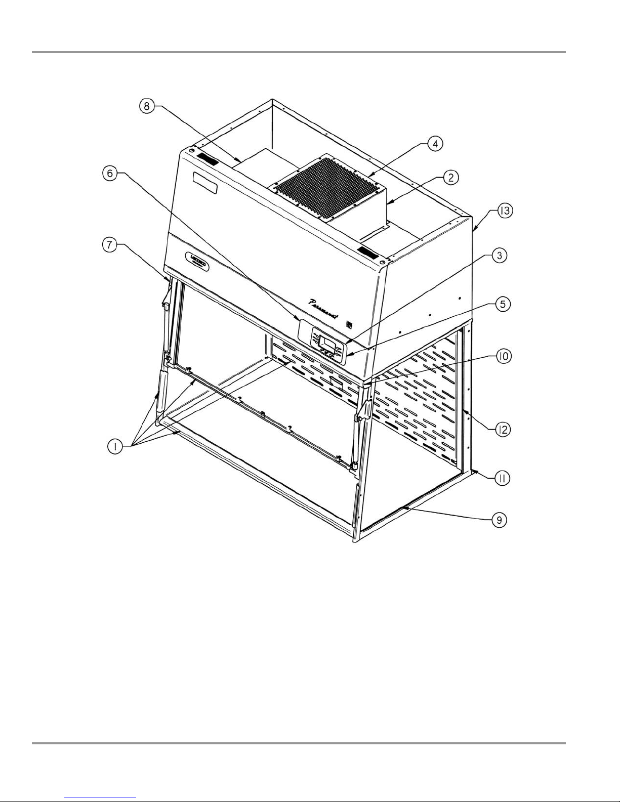
All Paramount Ductless Enclosures have the following performance features
as illustrated in Figure 4-1:
1. High Performance Containment
2. Safety-First™ Vapor Sensor
3. Smart-Flow™ Airflow Monitor
4. Quiet, Energy-Efficient ECM Impeller
5. Audible/Visual Alarms
6. Large Control Panel LCD Display
7. Ergonomic Sloped Front
8. Convenient Filter Replacement
9. Durable Construction
10. Fluorescent Light with Electronic Ballast
11. Utility Iris Ports
12. Maximum Visibility
13. Simple Electrical Connection
Product Service 1-800-522-7658
15
Page 21
Chapter 4: Performance Features and Safety Precautions
16
Figure 4-1
Performance Features
Product Service 1-800-522-7658
Page 22
Chapter 4: Performance Features and Safety Precautions
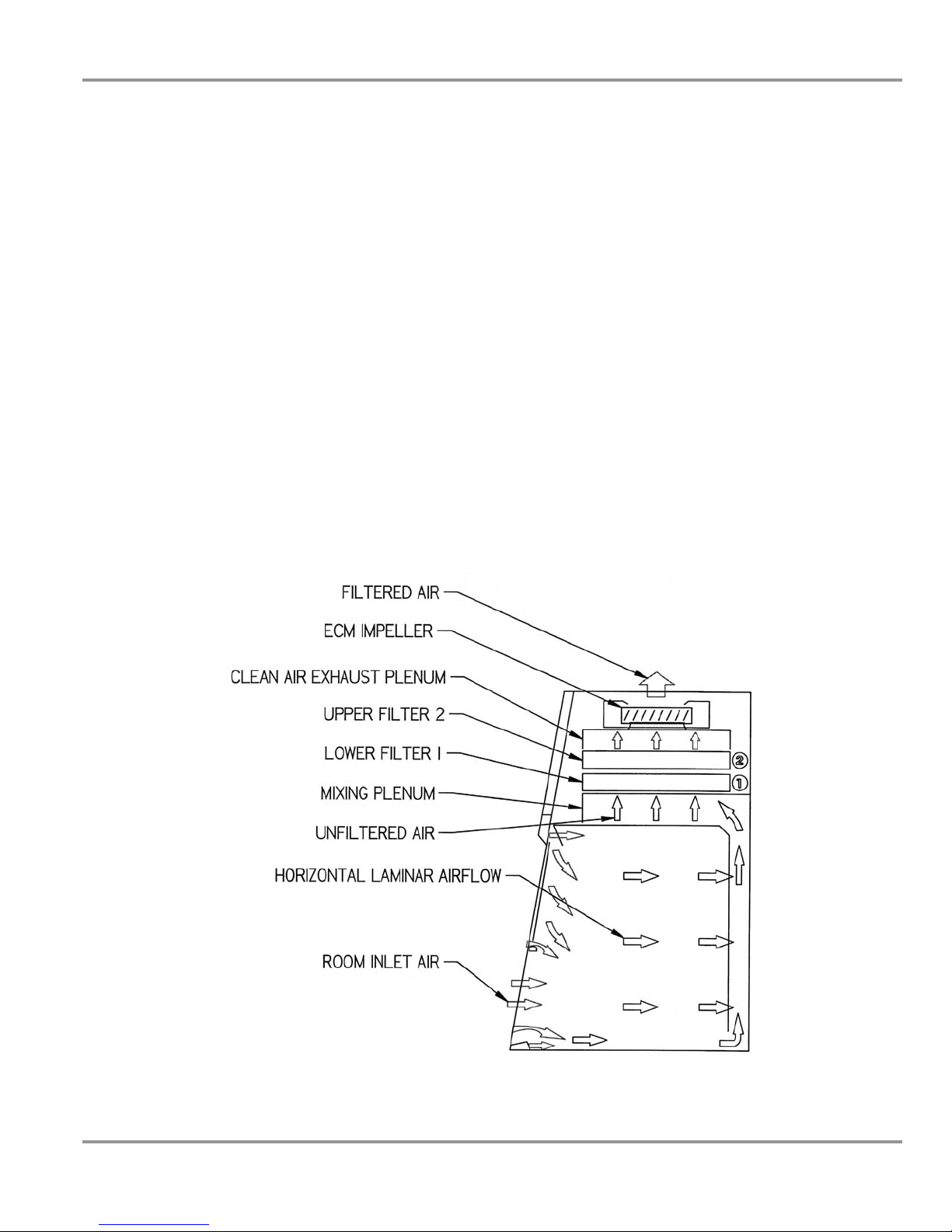
High Performance Containment
The Paramount Ductless Enclosures use patented technology to direct air into
and through the contaminated air chamber (U.S. Patent 6,461,233). The
containment enhancing and aerodynamic designs of the lower CleanSweep™ Air Foil, upper sash foil, side air foils, upper dilution air supply,
and zoned rear perforated baffle all work in concert to produce horizontal
airflow patterns that significantly reduce chemical concentrations through the
work area (illustrated in Figure 4-2). The unique lower air foil shape and
Clean-Sweep™ openings sweep the work surface and create a constant
protective barrier from contaminants. The radiused upper sash foil includes
an open air passage directly atop the sash foil into the enclosure chamber and
directs chemical concentrations away from the sash opening. The side entry
air foils allow turbulence-free air to enter the enclosure from the sides and
allow clean air to sweep the interior walls. The upper dilution air supply
provides by-pass air from above the work surface to constantly bathe the
inside of the sash and upper chamber with clean air to reduce chemical
concentrations. The zoned rear perforated baffle directs horizontal laminar
air streams to the three zones to minimize the potential for air to roll forward
preventing contaminants from moving toward the sash opening.
Product Service 1-800-522-7658
Figure 4-2
Airflow Diagram
17
Page 23
Chapter 4: Performance Features and Safety Precautions
Safety-First™ Vapor Sensor
The Safety-First™ Vapor Sensor detects filter saturation in the exhaust to
alert the operator to replace the filters. The early warning provided by the
Safety-First Vapor Sensor provides the user ample time (5-10% remaining
filter life) to complete work in process before replacing the filters. The early
warning signals with an intermittent beep and the LCD display message alerts
the user to replace filters. The final warning signals with a constant alarm
and the LCD display message alerts the user to replace filters. The SafetyFirst Vapor Sensor includes a primary and secondary backup sensor for
redundant monitoring. Both sensors detect typical organic vapor solvents,
smoke particulates, ammonia gases, formaldehyde gases and hydrogen
sulfide gases. The Safety-First Vapor Sensor has an optimal detection range
of 1-10 ppm. Typical concentrations tested by Labconco for chemicals in
separate chemical families are listed in order of sensor sensitivity as follows:
Chemical Family Chemical
Aldehydes & Ketones Cyclohexanone 0.2-0.5 ppm 0.068 50 22% OV
Mixture of Aliphatic
Hydrocarbons
Particulates Cigarette smoke 0.4-1.0 ppm N/A N/A N/A OV & HEPA
Aldehydes & Ketones Acetone 0.5-1.0 ppm 4.58 250 2% OV
Aromatic Hydrocarbons Toluene 0.5-1.0 ppm 0.16 100 20% OV
Ethers Methyl Tert-Butyl Ether 0.5-1.0 ppm 0.053 50 9% OV
Sulfur Compounds Hydrogen Sulfide 0.5-2.0 ppm 0.0005 10 10% AG, Acid-Sulfur
Nitrogen Compounds Diethylamine 1.5-2.0 ppm 0.186 10 7% OV
Esters Ethyl Acetate 1.5-4 ppm 0.61 400 9% OV
Ethers Diethyl Ether 2-4 ppm 2.29 400 4% OV
Aldehydes Formaldehyde 2-4 ppm, best to use
Nitrogen Compounds Ammonia Solution
Alcohols
Acids Acetic Acid 5-6 ppm 0.016 10 4% OV
Halogens Chlorobenzene 5-8 ppm 0.741 10 20% OV
Alcohols Isopropyl Alcohol 8-11 ppm 22 200 7% OV
Aliphatic Hydrocarbons Hexane 9-15 ppm 21.9 50 11% OV
Alcohols
Mineral Acids Hydrochloric Acid Not Detected, use other
Important Note: Clean up procedures using alcohols or volatile
*
Gasoline 0.3-1.0 ppm 0.3 300 11% OV
(Ammonium Hydroxide)
Ethyl Alcohol
Methanol
*
*
Sensitivity Alert
Concentration
other detector methods
2-5 ppm 5.75 25 10% AM, Ammonia-
2.5-4 ppm 0.136 1000 1.3% OV
15-25 ppm 141 200 0.1%,
detector means
Odor
Threshold
(ppm)
0.87 0.1 ceiling,
0.77 5 17% AG, Acid-Sulfur
chemicals with low filter capacity could saturate the filters quickly.
Important Note: The vapor sensor does not detect mineral acid gases such
as hydrochloric acid, nitric acid, or sulfuric acid and other detector means
such as a mineral acid sensor or interval timed sampling with sampling tubes
must be used.
Chemical Safety Note: The chart above is only a guideline! Frequent
chemical testing or filter monitoring is recommended for other chemicals. If
chemical suitability is ever in question, always work below the acceptable
exposure limit/TWA to maximize both safety and filter performance.
Exposure
Limit TWA
(ppm)
0.016
Filter
Capacity
(%W)
10% FORM
very low
Filter Type
Amine
not recommended
18
Product Service 1-800-522-7658
Page 24

Chapter 4: Performance Features and Safety Precautions
Smart-Flow™ Airflow Monitor
The Smart-Flow™ Airflow Monitor continuously monitors airflow and
displays face velocity. An audible/visual alarm alerts the user to low airflow
conditions. The Smart-Flow Airflow Monitor enables the motor speed to
automatically adjust for conditions such as temperature, barometric pressure,
and filter loading and maintain constant programmed airflow speed. The
Smart-Flow feedback maintains constant airflow speed through the use of
constant velocity pressure measurement accomplished with a pitot tube and
pressure sensor mounted on the control board. Transport, altitude, and
temperature differences require the airflow re-calibration steps as outlined in
Chapter 5 and 6. Use the “Calibration” menu in Chapter 5 to reset the
“Pressure Sensor” values for “motor speed” and “airflow face velocity.”
Quiet, Energy-Efficient ECM Impeller
The electronically commutated motorized (ECM) impeller is 95% energy
efficient providing “green” energy savings (See Appendix D). Because of
the high efficiency, the impeller runs extremely quiet for the comparative
amount of airflow volume. All Paramounts run at or below 62 dbA at 80 fpm
and most Paramounts run at or below 59 dbA at 80 fpm. By design, the ECM
impeller is located after the filters assuring an intrinsically safe design where
all contaminated air is filtered effectively. See Chapter 2: Prerequisites for
complete airflow exhaust volume, noise pressure, and face velocities of 60,
80 and 100 fpm. The ECM impeller has a programmable blower timer
should you desire additional “green” energy savings.
Audible/Visual Alarms
The audible/visual alarms remind the operator to check the filters with
sampling tubes or replace the filter. Filter replacement alarms occur in
audible/visual modes for both filter saturation activated by the Safety-First
Vapor Sensor or the final filter elapsed time. A low airflow alarm occurs
when the face velocity drops below programmed levels.
Large Control Panel LCD Display
The large (3" x 1.5") LCD message center provides continuous status reports
for each filter, displays airflow speed, and displays alarm messages for both
filters and airflow. The touchpad can be programmed for filter types, filter
check times, and filter replacement times. Audible/visual alert time messages
appear after the specified number of hours has elapsed. The audible/visual
alarm reminds the operator to check the filters with sampling tubes or replace
the filters. Filter replacement audible/visual alarms occur for both the SafetyFirst Vapor Sensor and final filter elapsed time.
Product Service 1-800-522-7658
19
Page 25

Chapter 4: Performance Features and Safety Precautions
Ergonomic Sloped Front
The ergonomic slope provides maximum visibility and comfort, reduces
glare, thereby minimizing operator fatigue. The space saving design (U.S.
Patent No. D538,941) increases effective laboratory work space, because the
impeller and filters are all self-contained within the enclosure and a separate
filtered blower unit is not required.
Convenient Filter Replacement
The Paramount filter compartment was designed to make filter replacement
convenient and easy. The gas spring assisted clamping mechanism opens
effortlessly and applies uniform pressure across the entire top surface of the
filters for leak-proof, one-step filter replacement from the front of the
enclosure.
Durable Construction
Unlike comparable plastic or acrylic ductless fume hoods and enclosures, the
Paramount Ductless Enclosure is manufactured with durable tempered safety
glass and dry powder epoxy-coated aluminum and steel. The sides and sash
are made from tempered safety glass that will not easily discolor or craze like
plastic. The frame is made from dry powder epoxy-coated aluminum and
steel providing further strength and corrosion resistance to solvents and acids.
Fluorescent Light with Electronic Ballast
The fluorescent light is located above the work area, out of contact with
contaminated air and easy to service. All Paramounts have a fluorescent light
and energy saving light timer with electronic ballast. The light timer is a
programmable feature should you desire additional “green” energy savings.
Utility Iris Ports
All Paramounts have two utility iris ports that allow electrical cords and data
cords to pass through the back of the enclosure without leaving a large hole
for contaminants to escape. The enclosure ships with both solid plugs and
iris ports for your convenience.
20
Product Service 1-800-522-7658
Page 26

Chapter 4: Performance Features and Safety Precautions
Maximum Visibility
Visibility is maximized on all units with at least 270 degree visibility from
both sides and the front pivoting sash. Some 3' and 4' models have 360
degree visibility which is especially useful in classroom demonstrations. See
Chapter 2: Prerequisites for model differences and model numbers.
Simple Electrical Connection
All 100-115V Paramounts are pre-wired with circuit breaker and IEC
electrical power cord that is simply plugged into a nearby electrical
receptacle. 230V units are shipped without a plug. Install the appropriate
plug for your electrical specification per local codes. All the impeller, light,
and airflow monitor wiring is internal and no electrical wiring connections
are needed. Paramounts are available in two voltages, 100-115V, 50/60 Hz
and 230V, 50/60 Hz. See Chapter 2: Prerequisites for model numbers.
Safety Precautions
1. Although the enclosure has been engineered to maintain optimum
operator safety, caution should always be used while working. Prior
to using the enclosure, check to make sure that the exhaust blower is
operating and that air is entering the enclosure at its specified face
velocity. The airflow monitor will alert the user to a problem with
airflow.
2. Use good housekeeping in the enclosure at all times. Clean up spills
immediately. Periodically clean enclosure interior.
3. Do not overload the work surface with apparatus or work material.
The safe operation of the enclosure is based upon having proper
airflow through the structure. Do not place large objects directly on
the work surface. Instead, elevate the object 3/4" on blocks to allow a
flow of air under the object and into the rear baffle exhaust slots.
Ensure blocks are level and secured in place.
4. Blocking large portions of the rear baffle will change the airflow
pattern in the enclosure causing turbulence. (Do not store containers
or supplies against the rear baffle, as this will affect airflow).
5. Always work with your hands as far back into the enclosure as
possible. Keep all powders, chemicals and apparatus inside the lower
air foil of the enclosure.
6. Do not work in this enclosure without the blower running and a face
velocity of 60-100 fpm.
7. Perchloric acid use in this enclosure is prohibited.
8. High-level radioisotope materials are prohibited in this enclosure.
Consult your Safety Officer.
Product Service 1-800-522-7658
21
Page 27

Chapter 4: Performance Features and Safety Precautions
9. Avoid cross drafts and limit traffic in front of the enclosure. Air
disturbances created may draw contaminants out of the enclosure.
10. A qualified certification technician should test the enclosure before it
is initially used. The enclosure should be validated whenever it is
relocated.
11. The use of safety goggles, protective clothing, gloves and any other
personal protective equipment recommended by your safety officer
should be used.
12. The sash must remain in the down position while using the enclosure.
13. Proper performance of the enclosure depends largely upon its location
and the operator’s work habits. Consult the references in Appendix D.
14. The enclosure should be recertified whenever it is serviced or at least
annually thereafter.
15. Use of an open flame must be avoided in the Paramount. Open
flames may disrupt the airflow patterns in the cabinet and cause a fire
hazard with volatile chemicals and solvents.
16. Handle new and used filters with care during installation and removal.
Refer to Installation Instructions in this manual for proper handling of
filters.
17. Saturated carbon filters and HEPA filters are to be disposed of as
hazardous waste. The user is responsible for recording the chemicals
adsorbed or removed by the filters and disposing of them properly.
18. Use in areas where only trained users have access to the enclosure.
Any new users must be trained and should also read this User’s
Manual.
19. Do not use the Paramount in a poorly ventilated area. If the
Paramount is to be used in a confined space, make sure the space is
well ventilated and the concentration of toxic contaminants cannot
accumulate greater than the exposure limit/TWA.
20. The warning properties (i.e., odor, taste) of the volatile organic
compounds or other material being used in the enclosure must be
adequate to provide an early indication that the carbon filter may be
saturated. In other words, it is best when the odor threshold is less
than the exposure limit/TWA.
21. Highly toxic vapors, unknown reaction, hazardous particulate, or
processes generating high levels of contaminants are not intended for
use in the Paramount.
22. Labconco Filter labels are color coded to match NIOSH respirator
types. Only chemicals which can be safely adsorbed/treated with the
specific carbon based filters installed or removed by HEPA filters are
appropriate for use in this enclosure.
22
Product Service 1-800-522-7658
Page 28

Chapter 4: Performance Features and Safety Precautions
23. Use the smallest possible quantity of chemical(s) within the enclosure
and never exceed the amount which can be effectively adsorbed by
the filters before breakthrough.
24. Leave the blower on for at least one minute after work in the
enclosure has been completed.
25. If a chemical is spilled on the work surface DO NOT switch off the
blower until all traces of the chemical has been removed.
26. Make sure filters are installed prior to each use. Remove the front
panel to install the filters.
27. If the blower fails during use, chemical processes should cease and
the area should be vacated and ventilated before servicing the blower.
28. Always refer to the Paramount Chemical Guide and/or the NIOSH
Pocket Guide to Chemical Hazards before proceeding. For additional
help with filter and chemical selection, contact Labconco at 800-8215525 or 816-333-8811.
29. The surface of the HEPA filter is fragile and should not be touched.
Care must be taken to avoid puncturing the HEPA filter during
installation or normal operation. If you suspect that a HEPA filter has
been damaged DO NOT use the enclosure; contact a local
certification agency or Labconco. Reference Chapter 6 for the HEPA
filter certification procedure.
30. The HEPA filter in the enclosure will gradually accumulate airborne
particulate matter from the room and from work performed in the
enclosure. The rate of accumulation will depend upon the cleanliness
of the room air, the amount of time the enclosure is operating and the
nature of work being done in the enclosure.
31. Ensure that the ductless enclosure is connected to an electrical service
in accordance with local and national electrical codes. Failure to do
so may create a fire or electrical hazard. Do not remove or service
any electrical components without first disconnecting the enclosure
from electrical service.
32. Tag the enclosure with appropriate warning, if any filters have been
removed for service.
Product Service 1-800-522-7658
23
Page 29

Chapter 4: Performance Features and Safety Precautions
Misapplications that Could Result in a
Hazardous Situation
There is one scenario where the Paramount’s misapplication could be a part
of a hazardous condition. That situation is where;
1. the Inlet Concentration is greater than the exposure limit/TWA,
2. the filter becomes saturated,
3. the user continues to operate,
4. and the ventilation of the room is insufficient to dilute the exhaust of
the Paramount to below the exposure limit/TWA for the chemical.
Important Note: When the inlet concentration is greater than the exposure
limit/TWA, extra measures must be taken to monitor the number of air room
exchanges. A well designed room with proper air exchanges will properly
dilute the exhaust from the Paramount by a multiplier of 25%.
24
Product Service 1-800-522-7658
Page 30
CChhaapptteerr 55::
UUssiinngg tthhee DDuuccttlleessss EEnncclloossuurree
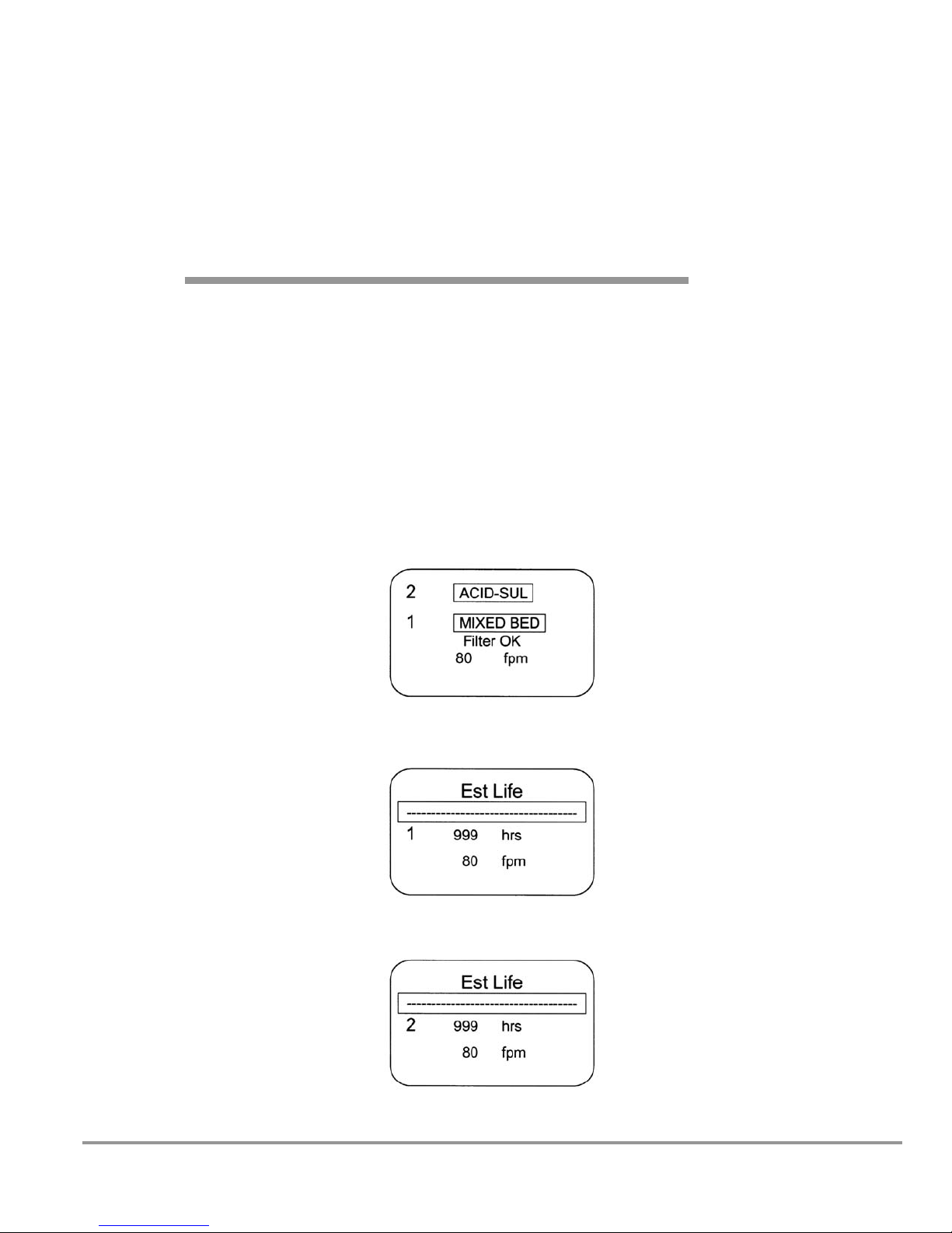
Information Center
The Information Center is an LCD display located on the control panel. The
center’s display is divided into three screens that alternate in normal mode, as
shown below to display filter status, estimated filter life, filter type, filter
replacement alarms, inflow face velocity, and airflow alarms.
Product Service 1-800-522-7658
25
Page 31

Chapter 5: Using The Ductless Enclosure
Status Area
The LCD displays the Paramount Ductless Enclosure’s condition during
operation such as the filter types, face velocity, and bar graph to display the
remaining filter life in hours. This line can display any of the following
messages:
Filters OK
Both filters are operating properly. (No audible alarm)
Check Filter-t
The filter check life timer has expired as programmed and the filters
should be checked with colormetric detector tubes or other
instrumentation. (Intermittent audible alarm)
Replace Filter-s or -t
The filter needs to be replaced immediately as either the Safety-First
Vapor Sensor (-s) has detected filter breakthrough or the filter final life
timer (-t) has expired. (Continuous audible alarm; can be muted for 5
minutes)
Note: The early warning signal that occurs with 5-10% remaining filter
life is an intermittent audible alarm along with “Replace Filter-s.”
Check Airflow
The airflow patterns in the ductless enclosure have changed, resulting in
a sudden change in the motor speed. This is most likely due to a
blockage of the exhaust filter outlet, complete blockage of the filters,
filter saturation, or motorized impeller failure. (Continuous audible
alarm; can be muted for 5 minutes)
Operating the Pivoting Sash
You can open or close the sash by pivoting the sash. A latch or gas spring
will retain the sash in the open position for loading only. Always work with
the sash in the closed position.
Starting the Ductless Enclosure
1. To start the ductless enclosure, press the “Blower” button.
2. To turn the fluorescent light on, press the “Light” button.
Note: The sash must be completely closed before performing work in the
enclosure.
26
Product Service 1-800-522-7658
Page 32

Chapter 5: Using The Ductless Enclosure
The Paramount Touchpad
The touchpad of the Paramount Ductless Enclosure is shown below. Take a
moment to get familiar with the buttons, their location and function. Also
familiarize yourself with the display located on the front. The display will
report system functions, such as filter types, filter life, timer displays, filter
status, and low airflow alarm messages.
Menu Button – This button toggles the display between menu modes. When
in the menu mode, this button returns you to the previous menu.
Filter Button – Automatically goes to the filter setup menu, which allows
you to display and change the programmable filter parameters such as filter
type, filter location, filter check time, and filter final time.
Mute Button
– Allows you to temporarily mute an alarm for 5 minutes.
Select Up/Down Yes/No Buttons – Allows you to change options and
values in the menu mode.
Enter Button
– Allows you to enter or select a value or select an option in
menu mode.
Timer Button
– Allows you to select either a repeating interval timer or an
elapsed timer.
Blower Button
– Starts or stops the enclosure blower. When the blower
button is activated, the inflow face velocity will register a face velocity.
Light Button
– Turns the fluorescent light on or off.
Product Service 1-800-522-7658
27
Page 33

Chapter 5: Using The Ductless Enclosure
All Program Screens
28
Product Service 1-800-522-7658
Page 34

Chapter 5: Using The Ductless Enclosure
Main Setup Screens
Product Service 1-800-522-7658
29
Page 35

Chapter 5: Using The Ductless Enclosure
Filter Setup Program Screens
30
Product Service 1-800-522-7658
Page 36
Chapter 5: Using The Ductless Enclosure
Calibration Program Screens
Product Service 1-800-522-7658
31
Page 37

Chapter 5: Using The Ductless Enclosure
Diagnostic Program Screens
Pressure Sensor Diagnostic Notes:
X20 CAL example represents a
pressure of 134 with the impeller off
and 212 with the motor speed at 157
producing 90 fpm for this calibration
example. With Smart Flow enabled,
the Paramount maintains constant
pressure as indicated by the pitot
tube and pressure sensor to maintain
constant airflow face velocity.
32
Organic Sensor Diagnostic Notes:
Organic Sensor example represents
sensor S1 calibrated in clean air at
1400 millivolts. When sensor S1
sees an increase of 400 millivolts to
1800 millivolts, the Early Warning
“Replace Filter-s” appears on the
LCD display with an intermittent beep
as only 5-10% filter life remains.
Filters should be changed upon
completion of work. When sensor S1
sees an increase of 500 millivolts to
1900 millivolts, the Final “Replace
Filter-s” Alarm sounds a continuous
beep that can only be muted for 5
minutes.
Product Service 1-800-522-7658
Page 38

Chapter 5: Using The Ductless Enclosure
User Selectable Features
The Paramount Ductless Enclosure offers the user unsurpassed flexibility and
convenience.
To access the menu, press the “MENU” button. The LCD display panel
will show the first level menu. To select from the various menu options
press the “▲” and “▼” buttons until the selected option is displayed.
Press “ENTER” to accept that option, or press “MENU” to return to the
previous menu.
For further explanation of the menu and its options, please refer to the
Paramount Touchpad at the beginning of Chapter 5.
Clock Timer Operation
NOTE: The Timer button displays the menu functions of an Interval
(countdown) Timer or Elapsed (stopwatch) Timer. The timers cannot be
operated simultaneously.
To access the main timer menu, press the “TIMER” button anytime during
normal operation. The main timer menu is shown on the LCD display. Use
the “▲” and “▼” buttons to highlight the Interval or Elapsed Timer. Press
the “Enter” button to select the highlighted timer function.
Interval Timer Operation
1. When selected, the Interval Timer menu is displayed on the LCD.
The timer defaults to 0:00:00 (hours:minutes:seconds).
2. Press and hold the “▲” or “▼” buttons to increase or decrease the
timer interval.
3. When the proper interval is entered on the display, press the
“ENTER” button to start the timer.
4. When the timer reaches 0:00:00, an audible alarm will sound, and the
timer will reset itself and repeat the countdown.
5. Press the “ENTER” button to pause the timer.
6. Press the “MENU” button to clear the interval timer and return to the
main timer menu.
Elapsed Timer Operation
1. When selected, the Elapsed Timer menu is displayed on the LCD.
The timer defaults to 0:00:00 (hours:minutes:seconds),
2. Press the “ENTER” button to start the timer.
3. Press the “ENTER” button again to zero the timer.
4. Press the “MENU” button to clear the elapsed timer and return to the
main timer menu.
Product Service 1-800-522-7658
33
Page 39

Chapter 5: Using The Ductless Enclosure
Light Lamp Timer and Blower Timer
Both timers allow you to decide whether the fluorescent lamp or blower will
operate continuously or for a limited time period that you select. This may be
desired for energy-savings as well as a safeguard for light-sensitive materials.
Interval
When the “interval” option is selected, the Light Lamp Timer or Blower
Timer menu is displayed.
Interval Timer
This window lets you set the amount of time for the fluorescent
lamp to stay lit once activated or the blower to stay running. Use the
“▲” and “▼” buttons to select the amount of time, then press the
“ENTER” button to set the interval.
Continuous
In the continuous mode, the fluorescent lights or blower will remain
on until the “LIGHT” button is pressed, or the “BLOWER” button is
pressed.
Blower Operation
This blower switch allows you to run the ductless enclosure and the face
velocity will be displayed. Note: Always work in the ductless enclosure with
the blower running.
Enclosure Set Up
These selections allow for the customization of the display and the ductless
enclosure operation.
Units of Measure
This option allows you to select the air velocity units of measure. When
“Metric” is selected, the air velocities are displayed in meters-persecond. When “US” is selected, the velocities are displayed in feet-perminute.
Security Lock
NOTE: The security lock automatically reactivates and locks out
the keypad.
The security lock feature prevents parameters of the Paramount from
being changed by unauthorized users. To engage the security lock,
access the Security Lock submenu. Select the “ON” option, and press
the “ENTER” button. Once engaged, the operator must enter the proper
password to lock or unlock the enclosure.
34
Product Service 1-800-522-7658
Page 40

Chapter 5: Using The Ductless Enclosure
Filter Setup Display Options
This menu selection determines which filters are loaded and displayed in
the lower and upper positions. One of seven filter types must be selected
for each filter position.
The filter check time and filter final life must be selected next for each
filter position. Consult Chapter 3, Appendix E, the Labconco Specialist,
and the Paramount Chemical Guide for proper program times.
Restoring Software Default Settings
To restore the default settings to their original configuration:
1. Access the Menu, and select “SETUP.” Press “ENTER.”
2. In the Setup submenu, select “Restore Defaults.” Press “ENTER.”
Table of Default Settings
Blower: Smart-Flow enabled
Units of Measure: fpm
Security Lock: OFF, Non-secure
Timers: Blower and Light Timers disabled.
Filter Timers: Enabled; Interval set at 100 hours, Final set at
500 hours.
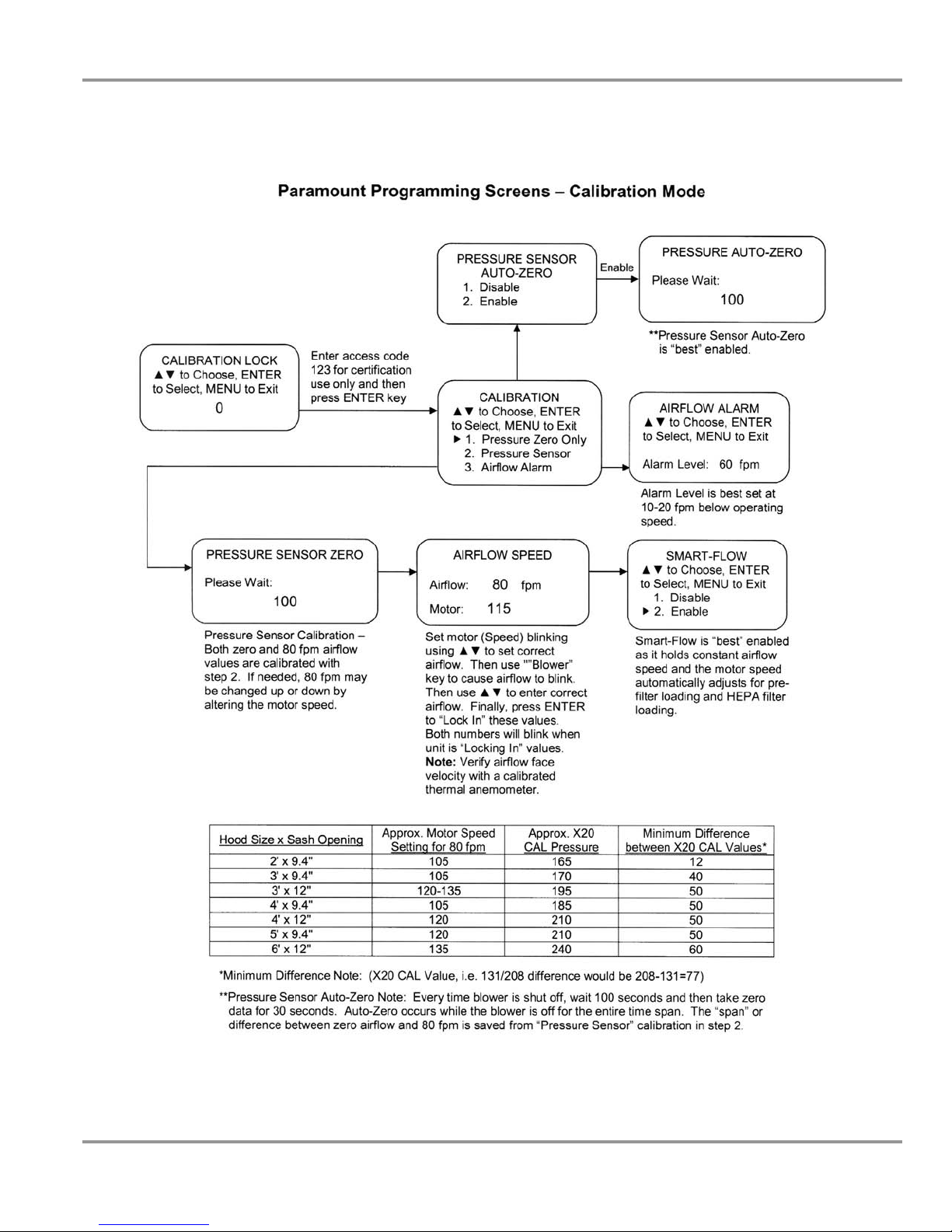
Calibration
This password-protected selection is for qualified certifiers to adjust the
blower speed, face velocity, and the low airflow alarm setpoint. Certifier
access code is set at 123.
Diagnostic Test Operation
When the “Diagnostic Test” menu is selected, the LCD allows “Keypad
Test” to help troubleshoot any malfunction. The “Pressure Sensor”
displays pressure values to help troubleshoot an airflow malfunction.
The “Organic Sensor” displays chemical breakthrough (millivolt
readings) and alarm setpoints to troubleshoot an organic sensor
malfunction.
Product Service 1-800-522-7658
35
Page 41

Chapter 5: Using The Ductless Enclosure
If a Check Airflow Activates
The most common causes of a check airflow alarm are:
• Blockage of the inlet perforated baffle or exhaust outlet.
• Loading or blockage of the filters resulting in low airflow.
• Motorized impeller failure or faulty electrical connector to the impeller.
Note: If the alarm sounds during use, immediately take appropriate action to
prevent contamination to you and other personnel in the area.
Resetting the Airflow Alert System
The Check Airflow Alarm automatically resets to normal operation and
displays the face velocity once the face velocity has increased and stabilized.
Working In the Paramount Ductless Enclosure
Planning
• Thoroughly understand procedures and equipment required before
beginning work.
• Arrange for minimal disruptions, such as room traffic or entry into the
room while the cabinet is in use.
Start-up
• Turn on blower and observe face velocity.
• Turn on the fluorescent light.
• Allow the enclosure to operate unobstructed for 1 minute.
• Wear a long sleeved lab coat with knit cuffs and over-the-cuff rubber
gloves. Use protective eyewear. Wear a protective mask if appropriate.
Loading Materials and Equipment
• Only load the materials required for the procedure. Do not overload
the enclosure.
• Do not obstruct the enclosure’s perforated baffle.
• Large objects should not be placed close together.
• Always operate with the sash in the closed position.
36
Product Service 1-800-522-7658
Page 42

Chapter 5: Using The Ductless Enclosure
Work Techniques
• Keep all materials a minimum of 4 inches (100 mm) from the inside
of the lower air foil, and perform all contaminated operations as far to
the rear of the work area as possible.
• Segregate all clean and contaminated materials in the work area.
• Arrange materials to minimize the movement of contaminated
materials into clean areas.
• Keep all discarded contaminated material to the rear of the work area.
• Avoid moving materials or the operator's hands and arms through the
front access opening during use.
• Avoid the use of an open flame.
• Avoid using techniques or procedures that disrupt the airflow patterns
of the enclosure.
Final Purging
• Upon completion of work, the enclosure should be allowed to operate
for two to three minutes undisturbed, to purge airborne contaminants
from the work area.
Unloading Materials and Equipment
• Objects in contact with contaminated material should be surface
decontaminated before removal from the enclosure.
• All open trays or containers should be covered before being removed
from the enclosure.
Wipe-Down
• Wipe down the interior surfaces of the enclosure with suitable
solvent, disinfectant, or cleaner. Important Note:
Clean up
procedures using alcohols or volatile chemicals with low filter
capacity could saturate the filters quickly.
• Dispose of used rubber gloves appropriately, and have
soiled/contaminated lab coats laundered properly.
• Wash hands and arms thoroughly with soap.
Shutdown
• Turn off the fluorescent light and enclosure blower to preserve filter life.
Product Service 1-800-522-7658
37
Page 43

CChhaapptteerr 66::
MMaaiinnttaaiinniinngg tthhee DDuuccttlleessss
EEnncclloossuurree
Replacing the carbon filters, HEPA filters, and fluorescent light is the
primary routine maintenance required.
Review this chapter on maintenance for the following:
• Routine Maintenance.
• Determination of when to replace carbon filters.
• Determination of when to replace HEPA filters.
• Install carbon filters and/or HEPA filters.
• Set Filter Life and Filter Check Timers.
• HEPA filter leak test.
• Reset or change the inflow face velocity, if necessary.
• Initial Certification.
• Re-Certification.
• Fluorescent light replacement.
• Motorized impeller replacement.
• Main control board replacement.
• Organic sensor board replacement.
Routine Maintenance Schedule
Weekly
• Wipe down the interior surfaces of the enclosure with a suitable
solvent, disinfectant, or cleaner, depending upon the usage of the unit
and allow to dry.
• Using a damp cloth, clean the exterior surfaces of the enclosure,
particularly the front and top to remove any accumulated dust.
• Operate the exhaust system, noting the airflow velocity on the display
and airflow through the enclosure using a source of visible smoke.
38
Product Service 1-800-522-7658
Page 44

Chapter 6: Maintaining the Ductless Enclosure
Quarterly (or more often as required)
• Note the airflow velocity on the display. Determine the actual airflow
face velocity through the sash opening of the enclosure where the
average reading should be at the specified velocity. (Use calibrated
thermal anemometer or other approved apparatus).
• The enclosure’s perforated baffle should be checked for any blockage
to ensure that the enclosure is maintaining proper airflow.
• Replace carbon filters when chemical breakthrough is indicated by
organic sensor, odor, time, detector tube, or for some chemicals,
analytical instrumentation. See “Install Carbon Filters” section of this
manual in Chapter 3.
• While the enclosure is filled with a contaminant, test filter condition
on carbon filters using the appropriate gas detector tube at intervals
of 20% of the total estimated time. The exception to the 20%
recommendation is formaldehyde or any carcinogen or suspected
carcinogen. These hazardous chemicals must be checked at a
minimum of every 10% of the total estimated time. Gas detector
tubes for the specific chemicals that are being used in the enclosure
can be obtained from your laboratory supply dealer.
• All weekly activities.
Annually
• Replace fluorescent lamps, if necessary.
• Replace HEPA filters if the face velocity drops below the
recommended speed for your facility as the airflow alarm alerts you.
• Have the enclosure validated by a qualified certification technician.
See Certification and Recertification in Chapter 6.
• All quarterly activities.
Determination of When to Replace Carbon Filters
The carbon filters MUST be replaced when any one of the following four
conditions are met:
1. The Safety-First Vapor Sensor indicates chemical breakthrough with an
audible alarm and the display reads “Replace Filters.”
2. The Filter Life timer has expired as programmed for typical usage.
3. Chemical odor in the work area is detectable, or the concentration of the
chemical in the work area is greater than the exposure limit/TWA.
4. Gas detector tubes change color when sampling the ductless enclosure
outlet (exhaust), indicating breakthrough.
Product Service 1-800-522-7658
39
Page 45

Chapter 6: Maintaining the Ductless Enclosure
There are five means of determining when its time to change the carbon
filters (not shown in the order of preference).
Odor - A person’s sensitivity to odor, tolerance of odor and their comfort
level under odoriferous conditions vary with the individual. Odor is an
indicator that chemicals are passing through the carbon filter. Additionally,
several points need to be understood:
• Odor can be used as a prompt to sample the exhaust to confirm
breakthrough.
• Organic chemicals approved for use in the ductless hood usually have
odors that are detectable before reaching the time weighted exposure
limits.
Safety-First Vapor Sensor - The organic sensor detects filter saturation
from exhaust gas concentration to alert the operator to replace filters. The
electronic sensor will signal when the concentration is under 5 ppm for most
chemicals with a range of 0.1-30 ppm. The early warning provided by the
Safety-First Vapor Sensor provides the user ample time (5-10% remaining
filter life) to complete work in process before replacing the filters. The vapor
sensor includes a primary and backup sensor for redundant monitoring and
both sensors detect typical organic solvents, smoke particulates, ammonia
gases, formaldehyde gases, and hydrogen sulfide gases; the vapor sensor does
not detect mineral acid gases such as hydrochloric acid, nitric acid, or sulfuric
acid. Consult the table in Chapter 4 for a partial listing of tested chemicals in
order of sensitivity as the sensitivity differs for each chemical; most tested
chemicals have a sensitivity alert concentration below 5 ppm as provided in
the table in Chapter 4.
Safety Note: The use of the organic sensor is not recommended for the
determination of filter saturation when the exposure limit/TWA for the
chemical is under 5 ppm. Other detection methods must be implemented
unless testing is performed by the end user and the known exhaust
concentration is below the acceptable exposure limit/TWA.
Detection Tubes - Color change indicators can be used to measure the
concentration of the chemical at the exit side of the carbon filter, between
filters, or in the outlet exhaust. A kit including syringe pump and flexible
tubing can be purchased as an accessory from Labconco (Catalog #
6924900). Labconco Customer Service Representatives are supplied with
detector tube catalog numbers, as well as telephone numbers to direct you to
where to purchase these items.
For organic, mineral acid, formaldehyde and ammonia, chemical specific
detector tubes should be purchased when installing fresh filters. Each kit
contains instructions on how many strokes of the syringe are required to
obtain the stated sensitivity. The sampling syringe is connected to the
ductless enclosure exhaust. The hose from the sampling syringe inlet can be
40
Product Service 1-800-522-7658
Page 46

Chapter 6: Maintaining the Ductless Enclosure
inserted between the stacked filters to sample the lower filter or inserted
through the holes in the blower exhaust cover to sample both filters. Connect
the syringe to the detector tube while the system is running and pull the air
through the tube with the syringe. Each stroke of the syringe represents a
100-ml sample and corresponds to the number of strokes necessary to give
the indicated color changes. Due to the wide variety of organics and varying
exposure limit/TWA’s, it is recommended that specific detector tubes be
purchased directly from Sensidyne, Dräger or your laboratory supply dealer.
Alternate detector pumps can also be purchased from your laboratory supply
dealers.
The vast majority of detector tubes available start measuring at the exposure
limit/TWA and the concentration value measured is not important. When a
user observes any color change in the tube, they should replace the filter
immediately. If no detector tube for your specific chemical is available, other
means of detection must be used.
Time - For applications that have very consistent inlet concentrations and
operating time, “Time” can be used to anticipate saturation or exposure
limit/TWA levels based on prior experience. However, this does not replace
the need for sampling. Consult Labconco Specialist for an estimate of carbon
filter life based on chemical usage. Refer to Chapter 3 on how to “Set the
Filter Life and Filter Check Timers.” Detector tubes, or analytical
instrumentation should always be used to determine concentrations in the
carbon filter. It is recommended that the carbon filters be checked with
detector tubes or other means at intervals of 20% of the total estimated filter
life. The exception to the 20% recommendation is formaldehyde and any
carcinogen or suspected carcinogen. These more hazardous chemicals must
be checked at least every 10% of the total estimated time.
Analytical Instrumentation - This is the most accurate means of measuring
concentrations of any chemical. It is the method of choice when no detector
tubes are available or the tubes are not sensitive enough to measure at the
exposure limit/TWA concentration for the chemical. This method is also to
be used to determine saturation when the chemical concentration is below the
measurement range of detector tubes. One relatively low cost method of
analytical instrumentation includes the use of a PID (photoionization
detector) that measures gas concentrations and is available from RAE
Systems or PID Analyzers, LLC.
Determination of When to Replace HEPA Filters
The HEPA filters in ductless enclosures gradually accumulate airborne
particulate matter and powders from the enclosure and room. The rate of
accumulation will depend upon the cleanliness of the room air, the amount of
time the enclosure is operating, and the nature of work being done in the
enclosure. Replace HEPA filters if the face velocity drops below the
recommended velocity. Replace HEPA filters if it fails the HEPA Filter Leak
Test in Chapter 6.
Product Service 1-800-522-7658
41
Page 47

Chapter 6: Maintaining the Ductless Enclosure
Install Carbon Filters and/or HEPA Filters
Refer to the instructions in Chapter 3 on filter installation during startup.
Set Filter Life and Filter Check Timers
Refer to the instructions in Chapter 3 on setting the Filter Life and Filter
Check Life Timers. Refer to the Filter Setup menus in Chapter 5.
HEPA Filter Leak Test
Purpose
After installing the new HEPA filter, the HEPA filter can be leak checked.
This test is performed to determine the integrity of the HEPA filter, the filter
housing, and the filter mounting frames. Leak testing is to be done by a
qualified technician with calibrated equipment. Leak check testing is
performed as a downstream average above the perforated exhaust cover
above the motorized impeller. The filter passes the leak test at .01% or
better. Reference Leak Testing and Photometer scanning from the Institute
of Environmental Services (IES-RP-CC001.3)
Apparatus
1. An aerosol photometer ATI model 2D, 2E, 2G or equivalent. Air
Techniques Hamilton Associates inc. 11403 Cron Ridge Dr. Owings
Mills, MD 21117
2. One aerosol generator of the Laskin nozzle(s) type. An aerosol of
mineral oil or suitable liquid shall be created by flowing air through it.
The compressed air supplied to the generator should be adjusted to a
pressure of 10± 1 psig. during operation. Air Techniques Inc. Model
TDA-4A or equal. One nozzle at 10 psig is (67.5 cfm x 100ug/l)/(Vol. of
air), For the 2' at 80 fpm or 115 cfm, one nozzle @10 psig is 6,750/115
cfm = 59 ug/l. For the 3' at 80 fpm or 230 cfm, one nozzle @ 10 psig is
29 ug/l. For the 4' at 80 fpm or 305 cfm, one nozzle at 10 psig is 22 ug/l.
For the 5' at 80 fpm or 295 cfm, one nozzle at 10 psig is 23 ug/l. For the
6' at 80 fpm or 230 cfm (two impellers draw 465 cfm), one nozzle at 10
psig is 29 ug/l.
3. Mineral oil (Catalog #1491400).
4. Sampling Nozzle, Rectangular 1/2" x 3-1/4", Air Techniques, Inc.
42
Product Service 1-800-522-7658
Page 48

Chapter 6: Maintaining the Ductless Enclosure
Procedure
For the ATI 2G Photometer
1. Turn on the photometer and allow it to operate for a minimum of 5
minutes. Leave the valve in the “CLEAR” setting.
2. Press the “ENTER” keypad. Press the “REF” keypad.
3. The display will display “P1” for approximately 1 second, and then
display a numerical value.
4. Using the “^” or “ν” keypads, respectively, increase or decrease the
numerical value until it equals 59 (2'), 29 (3'), 22 (4'), 23 (5'), 29 (6') for
the enclosure at 80 fpm inflow velocity.
5. Press the “ENTER” Keypad. The photometer will scan for 15 seconds,
and then the “0” keypad will flash. Press the “Enter” keypad. The unit
will scan for 5 seconds, the display will read “0000,” and the unit will
sound a confirming tone.
6. Set the valve to “DOWNSTREAM.” Place the palm of your hand over
the sampling port of the pistol. There should be a strong vacuum at this
port. If the vacuum is weak, contact Air Techniques Hamilton Associates.
7. Turn the enclosure on and let it operate for a minimum of 5 minutes.
8. Maintain the following airflows at 80 fpm; 2' (115 cfm), 3' (230 cfm), 4'
(305 cfm.), 5' (295 cfm), 6' (230 cfm, each impeller).
9. Position the aerosol generator discharge in the intake of the baffle inside
the enclosure. For 6' sizes with two impellers, position the generator to
the far left and the far right to test each filter.
10. Start the aerosol generator (Pressure to be +/- 1 psig). (10 psig). Ensure
that one Laskin nozzle is in the “open” position.
11. Allow the generator to operate for a minimum of 15 seconds. For all
integral motorized impeller models, scan the downstream exhaust side of
the HEPA filter by passing the sampling nozzle of the gun above the
perforated exhaust cover above the impeller. Scan the entire periphery of
the perforated exhaust cover, within 1 inch of the surface.
Acceptance
Aerosol penetration as a downstream average shall not exceed 0.01 percent
measured by the photometer.
Product Service 1-800-522-7658
43
Page 49

Chapter 6: Maintaining the Ductless Enclosure
Change the Airflow Face Velocity (If Necessary)
The Paramount has been tested and shipped at a face velocity of 75-80 fpm.
If necessary, refer to the instructions in Chapter 3 to change the face velocity.
Refer to the “Calibration” menus in Chapter 5 that refer to the “Pressure
Sensor” and “Airflow Alarm.” The “Calibration” menus require a password
to protect the ductless enclosure integrity and the password can only be
obtained from Labconco Product Service for certifier use. The “Airflow
Alarm” should be set at 10-20 fpm below the normal operating face velocity
and it was tested and shipped at 60 fpm.
Initial Certification
The ductless enclosure has been certified at the factory for an inflow velocity
of 75-80 fpm. The ductless enclosure should be certified for the proper
inflow velocity required by your Safety Officer. Transport, altitude, or
temperature differences may require the “Calibration” of the “Pressure
Sensor” to be reset as outlined in Chapter 5: Using the Ductless Enclosure.
If a HEPA filter is used, it is a conservative recommendation to perform the
HEPA Filter Leak Test should there be any damage to the media caused
during transport.
Re-Certification
Under normal operating conditions, the enclosure should be recertified at
least annually if serviced. The certifier should perform the following tests.
• Airflow Velocity Test. If necessary, reset the Airflow Face Velocity and
Motor Speed per the “Calibration” of the “Pressure Sensor” menu listed
in Chapter 5.
• HEPA Filter Leak Test, if installed.
In addition, the following test should also be performed at the user’s
discretion:
• Smoke Test to determine proper airflow patterns.
44
Product Service 1-800-522-7658
Page 50

Chapter 6: Maintaining the Ductless Enclosure
Figure 6-1
Light Replacement
Fluorescent Light Replacement
1. Disconnect the power.
2. Locate the small light reflector located under the control panel shown
in Figure 6-1.
3. Remove the light reflector by removing two Phillips screws on the
bottom of the light reflector.
4. Remove the old fluorescent lamp from the light sockets and metal
support clips as shown in Figure 6-2.
5. Reinstall the new fluorescent lamp and light reflector in reverse order.
6. Power the unit up and try the new fluorescent lamp.
Product Service 1-800-522-7658
45
Page 51
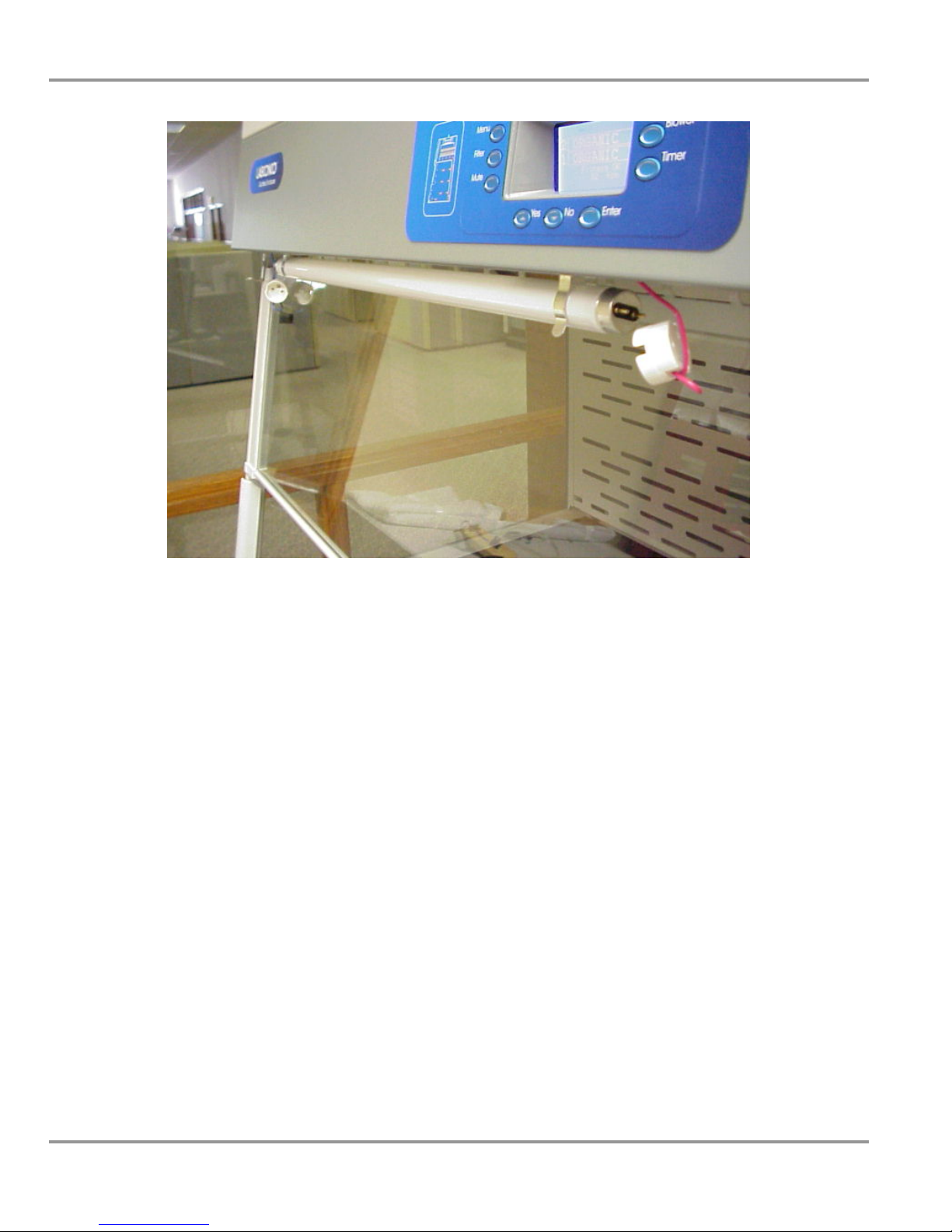
Chapter 6: Maintaining the Ductless Enclosure
Figure 6-2
Light Replacement
46
Product Service 1-800-522-7658
Page 52

Chapter 6: Maintaining the Ductless Enclosure
Motorized Impeller Replacement
The motorized impeller (ECM) must be replaced as a complete unit; it has
over 50,000 hours of useful life as tested. See Appendix A for Replacement
Parts Diagram. See Figure 6-3 for a view of the motorized impeller plenum
assembly.
1. Disconnect all power and consult the wiring diagram on the back of the
front panel and disconnect all the wires of the motorized impeller from
the quick disconnect connector. Be sure to connect wires on the new
motor in the same way the old motor was wired and not get the wires or
hoses tangled in the impeller.
2. Remove four screws in the motorized impeller bracket that hold it down.
Remove the motorized impeller and bracket.
WARNING: High-speed blower. Never operate impeller with housing
off.
3. Reassemble the new motorized impeller by reversing the assembly steps.
Figure 6-3
Motorized Impeller Replacement
Product Service 1-800-522-7658
47
Page 53

Chapter 6: Maintaining the Ductless Enclosure
Main Control Board Replacement
If the main control board is replaced, the Paramount must be calibrated per
the menu screens in Chapter 5. See Appendix A: Replacement Parts, and
reference Figure 6-4.
1. Consult the wiring diagram on the back of the front panel and disconnect
all power.
2. Remove the hardware to rotate the header control panel.
3. Locate the connectors to the main control board and remove the
connectors per the wiring diagram.
4. Label the two pressure hoses and remove the two pressure hoses from the
control board. The hoses must be installed properly with the front hose
corresponding with the front “total pressure” hose from the motorized
impeller assembly (front to front throughout).
5. Remove the control board from the plastic display bezel by removing the
four Phillips screws.
6. Reassemble the new control board in reverse order and follow the
“Calibration” menu screens from Chapter 5 as the Pressure Sensor,
Airflow Alarm, and Organic Sensor all need calibration.
48
Figure 6-4
Main Control Board
Product Service 1-800-522-7658
Page 54
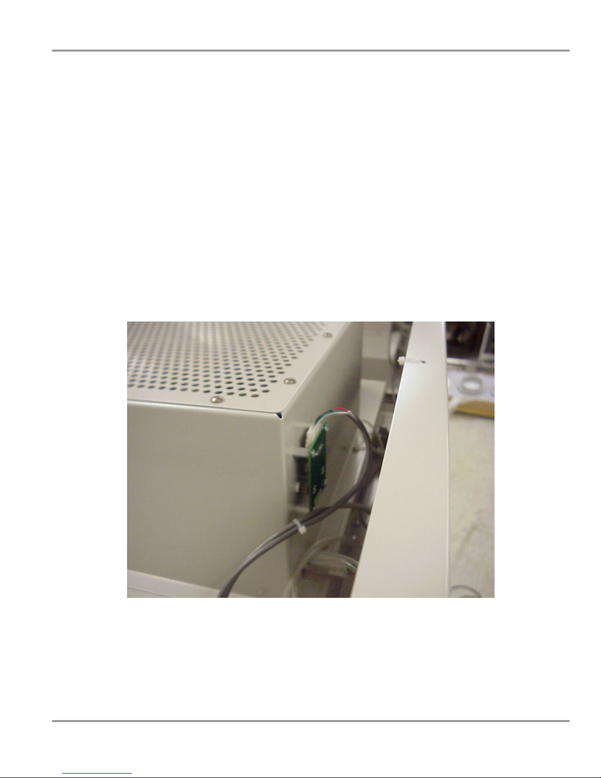
Chapter 6: Maintaining the Ductless Enclosure
Organic Sensor Board Replacement
If the organic sensor board is replaced, the Paramount must be calibrated for
the “Organic Sensor.” Contact Labconco Product Service. See Appendix A:
Replacement Parts and reference Figure 6-5. Please note that the 6'
Paramount utilizes two organic sensor boards, one for each motorized
impeller.
1. Consult the wiring diagram on the back of the front panel and disconnect
all power.
2. Remove the organic sensor connector as shown in Figure 6-5.
3. Remove the four Phillips screws that mount the organic sensor board.
4. Install the new organic sensor board in reverse order. Note: Be careful
with the delicate electronic sensors on the organic sensor board and do
not move them or rotate them.
5. Follow the “Calibration” menu screens from Chapter 5 as the Organic
Sensor needs calibration. A separate code and procedure is required and
Product Service must be contacted.
Product Service 1-800-522-7658
Figure 6-5
Organic Sensor Board
49
Page 55

CChhaapptteerr 77::
AAcccceessssoorriizziinngg tthhee DDuuccttlleessss
EEnncclloossuurree
There are several ways to accessorize and/or modify the ductless enclosure
for your individual requirements. These include the addition of carbon
filters, HEPA filters, work surfaces, impregnated carbon filters, base stands,
base stand shelves, storage cabinets, seismic support, exhaust transition,
remote blowers, exhaust dampers, utility shelf kits, syringe pump kits, deck
mounted valves with work surface and sash closures.
1. Filters
The Paramount Ductless Enclosure operates with seven different filter types
with at least one filter type required for successful operation:
Catalog # Description
6938100 HEPA Filter, 15" x 18" x 1.5", 99.99% efficient particulate
6938200 Activated Carbon Filter, Organic Vapor 7.5 lbs.
6938201 Impregnated Carbon Filter Acid-Sulfur 10 lbs.
6938202 Impregnated Carbon Filter, Ammonia-Amine 11 lbs.
6938203 Impregnated Carbon Filter, Formaldehyde-Formalin 10 lbs.
6938204 Mixed Bed Carbon Filter, Org. Vap., Acid-Sul., Ammon, Form (25% Mix) 10 lbs.
6938205 Impregnated Carbon Filter, Radioisotope 10 lbs.
The Paramount model sizes, filter compartments, and number of filters are
listed below for installation convenience.
Paramount
Size
2' 1 2 15 lbs.
3' 2 4 30 lbs.
4' 3 6 45 lbs.
5' 3 6 45 lbs.
6' 4 8 60 lbs.
Filter
Compartments
Required
No. of Filters
Total Organic
Vapor Filter Weight
50
Product Service 1-800-522-7658
Page 56

Chapter 7: Accessorizing the Ductless Enclosure
2. Work Surfaces
An optional work surface is available to attach to the ductless enclosure. The
black epoxy work surfaces are contoured to fit the dimensions of the ductless
enclosures to contain spills. The stainless work surfaces include a front
trough to contain spills. See Figure 3-1 for installation.
Catalog # Description Dimensions (W x D x H)
3909900 Black, 2' W x 29", Epoxy 24" x 29" x 1"
3909901 Black, 3' W x 29", Epoxy 36" x 29" x 1"
3909902 Black, 4' W x 29", Epoxy 48" x 29" x 1"
3909906 Black, 4' W x 35.5" Epoxy 48" x 35.5" x 1"
3975504 4' (Deep) Stainless w/Trough 48" x 35.5" x 0.8"
3909907 Black, 5' W x 29" Epoxy 60" x 29" x 1"
3909908 Black, 5' W x 35.5" Epoxy 60" x 35.5" x 1"
3975502 5' Stainless w/ Trough 60 x 29" x 0.8"
3975503 5' (Deep) Stainless w/ Trough 60" x 35.5" x 0.8"
3909910 Black, 6' W x 29" Epoxy 72" x 29" x 1"
3909911 Black, 6' W x 35.5" Epoxy 72” x 35.5" x 1"
3975602 6' Stainless w/ Trough 72" x 29" x 0.8"
3975603 6' (Deep) Stainless w/ Trough 72" x 35.5" x 0.8"
Product Service 1-800-522-7658
51
Page 57

Chapter 7: Accessorizing the Ductless Enclosure
3. Work Surface with Deck Mounted Valves, Gooseneck, and Cupsink
The work surfaces supplied with deck mounted valves allow the convenience of
water, air, and vacuum along with a cupsink and cold water gooseneck fixture.
NOTE: Work Surfaces with Deck Mounted Service Fixtures cannot
be used with a Protector Solvent Cabinet. Solvent Cabinets have a
top that cannot be penetrated.
Catalog # Description
6963800 3' w x 29" d Black Epoxy Work Surface w/three deck mounted
valves, cupsink, and gooseneck
6963801 4' w x 29" d Black Epoxy Work Surface w/three deck mounted
valves, cupsink, and gooseneck
6963802 5' w x 29" d Black Epoxy Work Surface w/three deck mounted
valves, cupsink, and gooseneck
6963803 6' w x 29" d Black Epoxy Work Surface w/three deck mounted
valves, cupsink, and gooseneck
52
Product Service 1-800-522-7658
Page 58

Chapter 7: Accessorizing the Ductless Enclosure
4. Base Stands, Accessory Shelves, Seismic Supports, and Hydraulic Lift Base
Stands
The following base stands, hydraulic lift base stands, accessory shelves, and
seismic supports may be used with the accessory work surfaces to support the
Paramount Ductless Enclosures. Hydraulic Lift Base Stands allow easy
movement up and down and through doorways as they are portable and can
be supplied with toe-locking casters.
Catalog # Description Size (if applicable)
3746700 2' Base Stand w/Feet 2' x 29" x 27.5"-33.5"
3746701 3' Base Stand w/Feet 3' x 29" x 27.5"-33.5"
3746702 4' Base Stand w/Feet 4' x 29" x 27.5"-33.5"
3746703 5' Base Stand w/Feet 5' x 29" x 27.5"-33.5"
3746704 6' Base Stand w/Feet 6' x 29" x 27.5"-33.5"
3746710 2' Base Stand w/Casters 2' x 29" x 27.5"-33.5"
3746711 3' Base Stand w/Casters 3' x 29" x 27.5"-33.5"
3746712 4' Base Stand w/Casters 4' x 29" x 27.5"-33.5"
3746713 5' Base Stand w/Casters 5' x 29" x 27.5"-33.5"
3746714 6' Base Stand w/Casters 6' x 29" x 27.5"-33.5"
3811100 2' Shelf, Base Stand 25.4” x 20.4"
3811101 3' Shelf, Base Stand 25.4" x 32.4"
3811102 4' Shelf, Base Stand 25.4" x 44.4"
3811103 5' Shelf, Base Stand 25.4" x 56.4"
3811104 6' Shelf, Base Stand 25.4" x 68.4"
3857000 Seismic Support Bracket Kit N/A
3780310 Portable 3' SoLo Hydraulic Lift Base Stand, 115V 53.5" x 34.3" x 17.2"-36.8"
3780314 Portable 3' SoLo Hydraulic Lift Base Stand, 230V 53.5" x 34.3" x 17.2"-36.8"
3780311 Portable 4' SoLo Hydraulic Lift Base Stand, 115V 65.5" x 34.3" x 17.2"-36.8"
3780315 Portable 4' SoLo Hydraulic Lift Base Stand, 230V 65.5" x 34.3" x 17.2"-36.8"
3780312 Portable 5' SoLo Hydraulic Lift Base Stand, 115V 77.5" x 34.3" x 17.2"-36.8"
3780316 Portable 5' SoLo Hydraulic Lift Base Stand, 230V 77.5" x 34.3" x 17.2"-36.8"
3780313 Portable 6' SoLo Hydraulic Lift Base Stand, 115V 89.5" x 34.3" x 17.2"-36.8"
3780317 Portable 6' SoLo Hydraulic Lift Base Stand, 230V 89.5" x 34.3" x 17.2"-36.8"
3780300 3' Electric Hydraulic Lift Base Stand, 115V, 60Hz 36.0" W x 29.0" Dp
3780303 3' Electric Hydraulic Lift Base Stand, 230V, 50Hz 36.0" W x 29.0" Dp
3780301 4' Electric Hydraulic Lift Base Stand, 115V, 60 Hz 48.0" W x 29.0" Dp
3780304 4' Electric Hydraulic Lift Base Stand, 230V, 50 Hz 48.0" W x 29.0" Dp
3780302 6' Electric Hydraulic Lift Base Stand, 115V, 60 Hz 72.0" W x 29.0" Dp
3780305 6' Electric Hydraulic Lift Base Stand, 230V, 50 Hz 72.0" W x 29.0" Dp
3780400 3' Manual Hydraulic Lift Base Stand 36.0" W x 29.0 Dp
3780401 4' Manual Hydraulic Lift Base Stand 48.0" W x 29.0" Dp
3780402 6' Manual Hydraulic Lift Base Stand 72.0" W x 29.0" Dp
3784000 Portable Caster Kit for Electric and Manual
Hydraulic Lift Base Stands
N/A
Product Service 1-800-522-7658
53
Page 59

Chapter 7: Accessorizing the Ductless Enclosure
5. Storage Cabinets
The following storage cabinets may be used with the accessory work surfaces
to support the Paramount Ductless Enclosures.
Size/Description Dual Doors Right Hinge Left Hinge Dual Doors Right Hinge Left Hinge
48" 9902000 - - 9901000 - 36" 9902100 - - 9901100 - 30" 9902200 - - 9901200 - 24" - 9902300 9902400 - 9901300 9901500
18" - - - - 9901400 9901600
48" w/Self-Closing Doors 9903000 - - - - 36" w/Self-Closing Doors 9903100 - - - - 30" w/Self-Closing Doors 9903200 - - - - 24" w/Self-Closing Doors - 9903300 9903400 - - 24" ADA - 9906000 9906100 - 9905000 9905200
24" ADA w/Self-Closing Doors - 9906200 9906300 - - 18" ADA - - - - 9905100 9905300
SOLVENT ACID
Size/Description Dual Doors Right Hinge Left Hinge Dual Doors Right Hinge Left Hinge
48" 9900000 - - - - 36" 9900100 - - - - 30" 9900200 - - - - 24" - 9900300 9900600 - - 18" - 9900400 9900700 - 9907000 9907100
12" - 9900500 9900800 - - -
STANDARD BASE VACUUM PUMP
54
Product Service 1-800-522-7658
Page 60

Chapter 7: Accessorizing the Ductless Enclosure
6. Exhaust Transitions
Canopy Exhaust Transitions connect each motorized impeller for ducting to
the outside. The Canopy Exhaust Transition is available for 6" nominal duct
(6' Paramount requiring two). The Canopy Exhaust Transition should be
sealed to the top of the enclosure with silicone sealant to prevent leaks.
Catalog # Description
6963700 Canopy Exhaust Transition (Paramount)
3927600 Flexible Hose, 6" ID Black with 6.09" ID cuffs, suitable for
pharmaceutical and clean room applications. 8' length with
two hose clamps.
Product Service 1-800-522-7658
55
Page 61
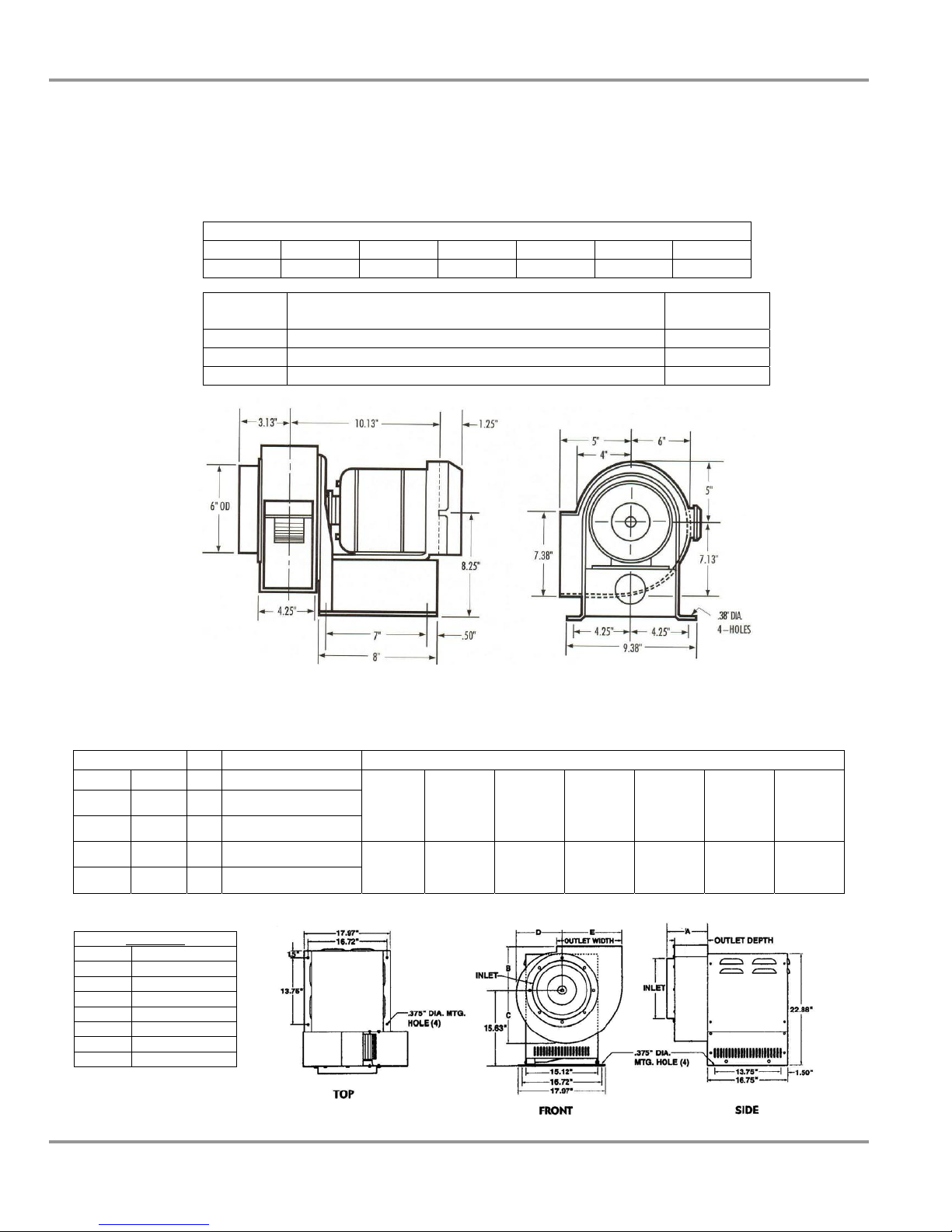
Chapter 7: Accessorizing the Ductless Enclosure
7. Remote Blowers – used to exhaust to the outside only.
6" nominal ID inlet blower has a 1/4 hp direct drive motor and corrosion-resistant
epoxy-coated steel housing and wheel with blower inlet of 6.00" ID. Outlet dimensions
are 4.25" x 7.38" OD.
CFM @ Static Pressure-Inches of H2O
S.P. 0.0" 0.125" 0.25" 0.50" 0.75" 0.87"
CFM 595 560 515 420 300 167
Catalog # Description
Shipping Wt.
(lbs./kg.)
4863500 Remote Blower, 115 V, 60 Hz. 4.4 amps 35/16
4863501 Remote Blower, 115/230 V, 50 Hz, 5.6/2.8 amps 35/16
7053501 Explosion-Proof Remote Blower, 115 V, 60 Hz, 4.4 amps 40/18
10" nominal ID inlet blower has a 1/4 hp or 1/3 hp adjustable belt drive motor and
corrosion resistant epoxy coated steel housing and wheel with blower inlet of 10.87" ID.
Outlet dimensions are 5.5" x 10" OD.
Catalog # HP Description CFM@RPM Ranges at Static Pressure (inches of H20)
Std. EP .25" .38" .50" .62" .75" .88" 1.00"
7068200 1/4
7068300 1/4
7068400 1/3
7068500 1/3
Remote Blower, 115V, 60
Hz, 4.4 A
Explosion Proof Blower
115V, 60 Hz, 4.5 A
Remote Blower, 115V, 60
Hz, 6.1 A
Explosion Proof Blower,
115V, 60 Hz, 6.4 A
540@800 410@800 350@870 390@970
720@950 760@1050 710@1060 620@1060
760@1050 710@1060 620@1060 430@1060 460@1150 500@1220
850@1130 825@1160 790@1190 770@1220 740@1260 640@1260
Dimensions
A 7.16"
B 7.00"
C 8.13"
D 6.81"
E 9.25"
Inlet 10.87" ID
Outlet 5.5"D x 10.0"W
Wheel 9.0" Dia.
56
Product Service 1-800-522-7658
Page 62
Chapter 7: Accessorizing the Ductless Enclosure
8. Exhaust Dampers
Exhaust dampers allow adjustments required to maintain proper airflow for
roof-mounted blowers or house exhaust systems.
Catalog # Description
3924000 6" Epoxy Coated Steel In-Line adjustable damper
4724200 6" PVC In-line adjustable damper
5983400 10" PVC In-line adjustable
3776800 10" Airtight Damper (10" tall)
9. Utility Shelf Kits and Holders
Labconco offers a utility shelf kit part number 3925000 consisting of three
shelves to hold items inside the enclosure. One shelf may be used for the
printer, one shelf for spatulas and weigh brushes, and one miscellaneous
shelf. The shelves hang from slots in the rear baffle.
Labconco also offers a 3927700 Bottle Holder with a 3" diameter opening
and a 3927800 Tissue Holder to hold a 4.63" x 4.75" box of tissues. These
holders also hang from slots in the rear baffle.
10. Syringe Pump Kit and Detector Tubes
The Syringe Pump Kit and chemical specific detector tubes may be used as a
timed detection means to determine filter replacement. Chemical specific
organic vapor detector tubes and pumps may be ordered from your laboratory
supply dealer or directly from Dräger, Inc. or Sensidyne.
Catalog # Description
6924900 Syringe Pump Kit
6925700 Detector Tubes, Ammonia – Pkg. of 3
6925800 Detector Tubes, Acid – Pkg. of 3
6926000 Detector Tubes, Formaldehyde – Pkg. of 3
Product Service 1-800-522-7658
57
Page 63
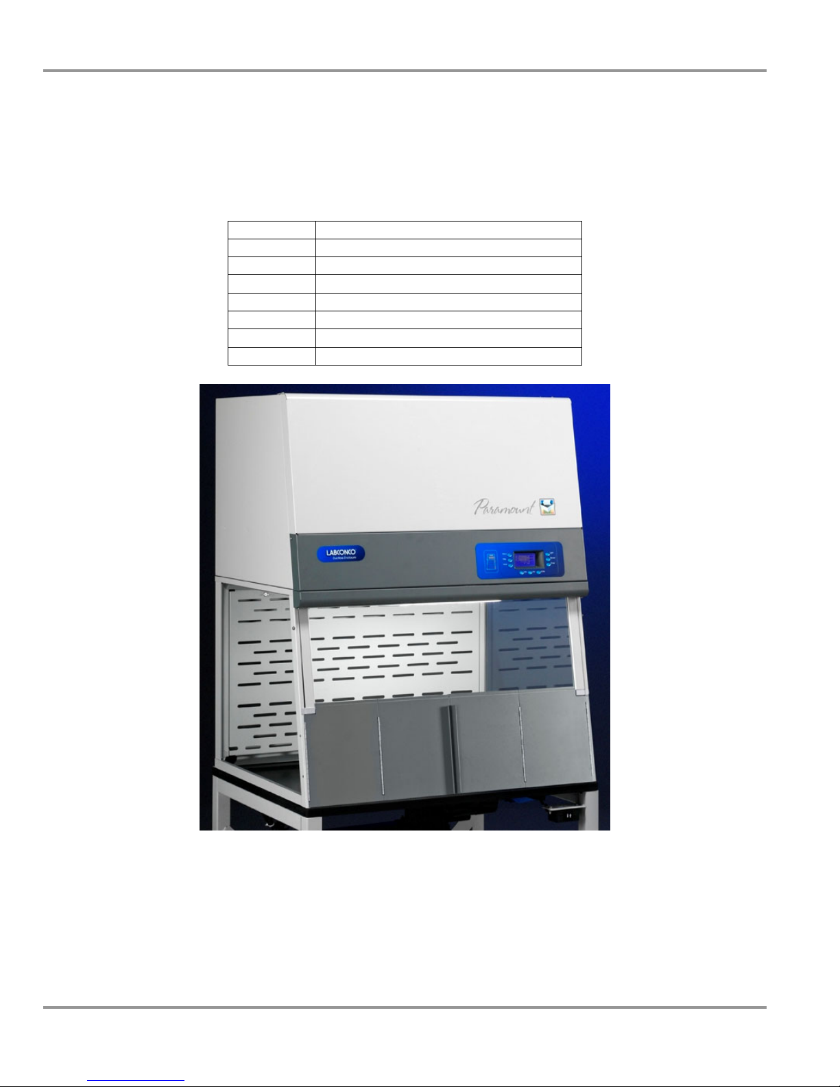
Chapter 7: Accessorizing the Ductless Enclosure
11. Sash Closures
All Paramount Ductless Enclosures have a standard sash opening at the bottom
consisting of 9.4" or 12". Sometimes it is necessary to close the lower sash
opening during operating procedures. The Sash Closure consists of bi-fold
doors to close the opening.
Catalog # Description
6963900 2' w x 9.4" h Sash Closure
6963901 3' w x 9.4" h Sash Closure
6963902 3' w x 12" h Sash Closure
6963903 4' w x 9.4" h Sash Closure
6963904 4' w x 12" h Sash Closure
6963905 5' w x 9.4" h Sash Closure
6963906 6' w x 12" h Sash Closure
58
Product Service 1-800-522-7658
Page 64

CChhaapptteerr 88::
TTrroouubblleesshhoooottiinngg
Refer to the following table if your ductless enclosure fails to operate
properly. If the suggested corrective actions do not solve your problem,
contact Labconco for additional assistance.
PROBLEM CAUSE CORRECTIVE ACTION
“Replace Filters”
continuous alarm
occurs
“Check Filters”
intermittent alarm
occurs frequently
Improper final time
programmed and
display reads “Replace
Filters-t”, (t = time)
Organic sensor alarms
and display reads
“Replace Filters-s”,
(s = organic sensor)
“Mute” will not stay
operational
Improper check time
programmed and
display reads “Check
Filters-t”, (t = time)
See Chapters 3 and 5 to properly set the
Filter Final Life Timer.
Organic sensor has detected filter
breakthrough. Replace filters
immediately. A spare set of filters
should always be on hand. Consult
Chapters 3, 4, and 5, the Labconco
Specialist, and the Chemical Guide for
estimated filter life based on specific
chemical use. All chemicals have a
different estimated filter life based on
specific chemical use. Always limit
chemical use, cover up chemicals when
not in use and turn off blower to
preserve filter life.
The “Mute” alarm can only be off for 5
minutes and must be pushed every 5
minutes until the filters have been
replaced. See Chapters 3, 5 & 6.
See Chapters 3 and 5 to properly set the
Filter Check Life Timer.
Product Service 1-800-522-7658
59
Page 65
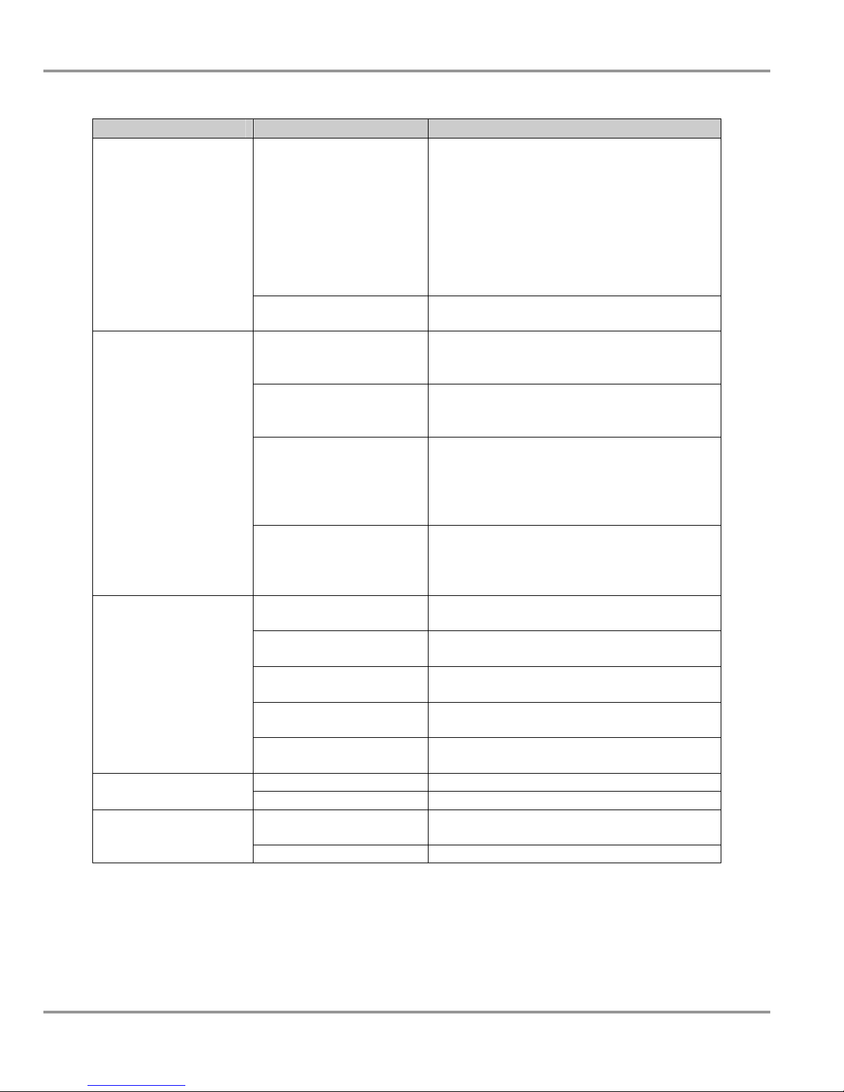
Chapter 8: Troubleshooting
PROBLEM CAUSE CORRECTIVE ACTION
Replace filters
intermittent alarm
occurs
Contaminants outside
of enclosure
Blower will not
operate
Low face velocity
Blower and lights will
not operate
Organic sensor alarms
intermittently and display
reads “Replace Filters-s”,
s = organic sensor
Carbon filter loaded with
chemicals.
Improper user techniques
for the enclosure.
Restriction of the baffle
air slots or blockage of
the exhaust outlet.
External factors are
disrupting the enclosure
airflow patterns or acting
as a source of
contamination.
Enclosure has improper
face velocity.
Unit not plugged into
outlet.
Circuit breaker(s) or
Ground Fault Interrupter.
Blower wiring is
disconnected.
Blower switch is
defective.
Motorized impeller is
defective.
Enclosure sash not closed. Close sash to the lowest position.
HEPA filter clogged. Replace HEPA filter.
Unit not plugged into
outlet.
Circuit breaker(s) tripped. Reset or replace circuit breaker.
Organic sensor has detected filter
breakthrough and only 5-10% of filter life
remains. Replace filters with a spare set of
filters stored. Consult Chapters 3, 4, and 5,
Filter Specialist, and Chemical Guide for
filter life based on specific chemical use. All
chemicals have different life. Always limit
chemical use, cover up chemicals and turn
off blower when not in used to preserve life.
Replace carbon filter.
See “Validate the Enclosure” Chapter 3 and
“Safety Precautions” Chapter 4 sections in
the manual.
Remove obstruction to ensure that all air
slots and the exhaust outlet are unobstructed.
See “Location Requirements” Chapter 2,
“Validate the Enclosure” Chapter 3, and
“Safety Precautions” Chapter 4 sections of
this manual.
Have enclosure certified per Chapter 6 and
check exhaust system. Check carbon filters
and replace if necessary. Enclosure should
have an average face velocity of 60-100 fpm.
Plug the enclosure into appropriate electrical
service.
Reset circuit breaker.
Inspect blower wiring.
Replace membrane switch on control panel.
Replace motorized impeller. See Chapter 6.
Plug enclosure into appropriate electrical
service.
60
Product Service 1-800-522-7658
Page 66

Chapter 8: Troubleshooting
PROBLEM CAUSE CORRECTIVE ACTION
Lights do not work
Airflow monitor
malfunction
Lamp not installed
properly.
Lamp wiring
disconnected.
Defective lamp. Replace lamp.
Light switch is defective. Replace membrane switch on control
Defective electronic
ballast.
No audible alarm. Alarm has been temporarily silenced
Wrong alarm set point. Airflow monitor alarm is preset at 60
Constant audible alarm. Check airflow and calibration of airflow
Continuous alarm. Check the face velocity of the enclosure
Low airflow. Check airflow and reset airflow monitor.
Inspect lamp installation.
Inspect lamp wiring.
panel.
Replace ballast.
using “mute” button.
fpm. Repeat calibration steps outlined in
this manual in Chapter 3, Chapter 5 and
Chapter 6.
monitor. See Chapter 5 & 6.
as the airflow of the system may have
changed. If incorrect, follow the
calibration steps in Chapters 3, 5 and 6.
The carbon filter pre-filter or HEPA filter
may have become loaded.
See Chapter 5 & 6. Look for filter
blockage or paper debris.
Product Service 1-800-522-7658
61
Page 67

AAppppeennddiixx AA::
RReeppllaacceem
meenntt PPaarrttss
The components that are available for your ductless enclosure are listed. The
parts shown are the most commonly requested. If other parts are required,
please contact Product Service.
Item Quantity Part No. Description
1A 1 6938100 HEPA Filter, 99.99% efficient on 0.3 micron, particulate
1B 1 6938200 Activated Carbon Filter, Organic Vapor, 7.5 lbs.
1C 1 6938201 Impregnated Acid-Sulfur Filter, 10 lbs.
1D 1 6938202 Impregnated Ammonia-Amine Filter, 11 lbs.
1E 1 6938203 Impregnated Formaldehyde-Formalin Filter, 10 lbs.
1F 1 6938204 25% Mixed Bed Carbon Filter, OV, Acid-Sul, Ammon, Form, 10 lbs.
1G 1 6938205 Impregnated Radioisotope Filter, 10 lbs.
2A 1 3991500 Sash Assy., 2' Short (22.7" IH)
2B 1 3991501 Sash Assy., 3' Short (22.7" IH)
2C 1 6970100 Sash Assy., 3' Tall (32" IH)
2D 1 3991502 Sash Assy., 4' Short (22.7" IH)
2E 1 6970101 Sash Assy., 4' Tall (32" IH)
2F 1 Sash Assy., 4' Extra Tall (35" IH)
2G 1 6976300 Sash Assy., 5' Tall (32" IH)
2H 1 Sash Assy., 5' Extra Tall (35" IH)
2I 1 3957301 Sash Assy., 6' Tall (32" IH)
2J 1 Sash Assy., 6' Extra Tall (35" IH)
3A 1 3907500 Sash Stop R.H.
3B 1 3907501 Sash Stop L.H.
4A 1 6916500 Latch, Sash
4B 1 3906700 Bracket, Latch
4C 1 1927403 Spring, Compression
4D 2 1893206 Screw, 8-32 x .38" lg. Phillips Pan S.S., Type F
4E 2 3973204 Sash Gas Spring Assy., 15# (3')
4F 2 3973203 Sash Gas Spring Assy., 20# (4')
4G 2 3973200 Sash Gas Spring Assy., 30# (5', 6')
5 1.9' 6913700 Wiper, Sash Seal
6A 2 1936800 Bushing, Closed 1.50" Dia.
6B 2 1934601 Bushing, w/Flex Shutter 1.50" Dia.
7 2 3915403 Side, Air Foil
8A 1 3907700 Light Reflector, 2' w
8B 1 3907701 Light Reflector, 3' w
8C 1 3907702 Light Reflector, 4' w
8D 1 3907703 Light Reflector, 5' w
8E 1 3907704 Light Reflector, 6' w
8F 2, 4 or 6 3908899 Reflector Tape
8G 2 1889308 Screw, #10-24 x 0.50 Phillips
62
Product Service 1-800-522-7658
Page 68

Appendix A: Replacement Parts
Item Quantity Part No. Description
9A 1 6964700 Front Panel, 2'
9B 1 6964701 Front Panel, 3'
9C 1 6964702 Front Panel, 4'
9D 1 6964703 Front Panel, 5'
9E 1 6964704 Front Panel, 6'
9F 1 6964101 Label, Front Panel
10 1 6964100 Membrane Switch
11A 1 6964300 ECM Motorized Impeller, 115V
11B 1 6964301 ECM Motorized Impeller, 230V
12A 1 1295500 Ballast, 2'
12B 1 1295400 Ballast (3', 4', 5', or 6')
13A 1 3708300 Lamp, Fluorescent 2' (F15T8-SP35)
13B 1 9721902 Lamp, Fluorescent 3' (F17T8)
13C 1 9721901 Lamp, Fluorescent 4' (F25T8)
13D 1 9721900 Lamp, Fluorescent 5' (F32T8)
13E 1 9721903 Lamp, Fluorescent 6' (F40T8)
13F 2 3836800 Lamp Holder Socket, Push-On
13G 2 3836700 Clip, Lampholder
14 1 6964500 Main Control Board
15A 1 or 2 6965200 Organic Sensor Board
15B 1 6967800 Harness, Organic Sensor, 2' w
15C 1 6967900 Harness, Organic Sensor, 3'-5' w
15D 1 6968000 Harness, Organic Sensor, 6' w
16A 1 6967500 Main Harness, 2' w
16B 1 6967600 Main Harness, 3', 4', 5', 6' w
16C 1 6967700 Main Harness, 6' w Extra ECM Blower
17A 1 or 2 1327204 Circuit Breaker, 5A (115V) - 2', 3', 4', 5' or (230V) - 6'
17B 2 1327200 Circuit Breaker, 3A (230V) - 2', 3', 4', 5'
17C 1 1327201 Circuit Breaker, 10A, 6' (115V)
18A 30' 1554304 Tubing, Pressure Sensor – Airflow
18B 1 or 2 6969300 Bracket, Pitot Tube – Airflow
18C 4 or 8 1449400 Fitting, Pitot – Airflow
18D 1 6977400 Connection Tee, 6' Unit
19A 1 1305800 Power Cord, 115V, Right Angle
19B 1 1305900 Power Cord, 230V, Right Angle
20A 1 or 2 6913000 Gas Assist Spring, Filter Clamping
20B 2 or 4 1906225 Jam Nut 3/8-16
20C 2 or 4 1910018 Lockwasher 3/8 Split
20D 2 or 4 1881712 Screw, 3/8-16 Hex, .75 lg.
Product Service 1-800-522-7658
63
Page 69
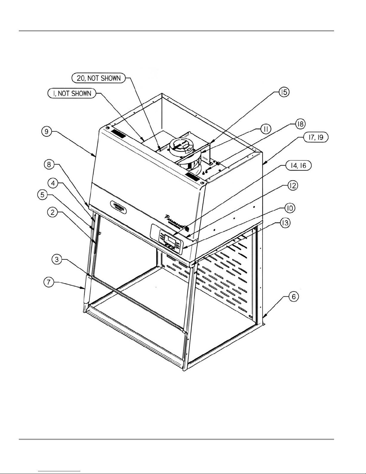
Appendix A: Components
A-1
64
Product Service 1-800-522-7658
Page 70

AAppppeennddiixx BB::
PPaarraam
moouunntt DDii
meennssiioonnss
m
Models Paramount Description A B C D E F
6963200, -20 2' Short 24.0 22.7 23.4 29.0 43.7 9.4
6963300, -20 3' Short 36.0 22.7 23.4 29.0 43.7 9.4
6963301, -21 3' Tall 36.0 32.0 23.4 29.0 53.0 12.0
6963302, -21 3' x 360 Visibility 36.0 32.0 23.4 29.0 53.0 12.0
6963400, -20 4' Short 48.0 22.7 23.4 29.0 43.7 9.4
6963401, -21 4' Tall 48.0 32.0 23.4 29.0 53.0 12.0
6963402, -22 4' x 360 Visibility 48.0 32.0 23.4 29.0 53.0 12.0
6963403, -23 4' Deep 48.0 35.0 30.0 35.5 56.0 12.0
6963501, -21 5' Tall 60.0 32.0 23.4 29.0 53.0 9.4
6963503, -23 5' Deep 60.0 35.0 30.0 35.5 56.0 9.4
6963601, -21 6' Tall 72.0 32.0 23.4 29.0 53.0 12.0
6963603, -23 6' Deep 72.0 35.0 30.0 35.5 56.0 12.0
(All dimensions in inches)
Product Service 1-800-522-7658
65
Page 71

AAppppeennddiixx CC::
SSppeecciiffiiccaattiioonnss
This Appendix contains technical information about all the Paramount
Ductless Enclosures including electrical specifications and environmental
operating conditions.
Electrical Specifications
• All 2', 3', 4', 5' Paramounts – 100-115V, 5 Amps, 50/60 Hz or 230V,
3 Amps, 50/60 Hz.
• 6' Paramounts – 100-115V, 10 Amps, 50/60 Hz or 230V, 5 Amps,
50/60 Hz.
Environmental Conditions
• Indoor use only.
• Maximum altitude: 10,000 feet (3,058 meters). Airflow must be
recalibrated at altitudes above or below 900 feet (275 meters).
• Ambient temperature range: 41° to 104°F (5° to 40°C).
• Maximum relative humidity: 80% for temperatures up to 88°F
(31°C), decreasing linearly to 50% relative humidity at 104°F (40°C).
• Main supply voltage fluctuations not to exceed ±10% of the nominal
voltage.
• Transient overvoltages according to Installation Categories II
(Overvoltage Categories per IEC 1010). Temporary voltage spikes on
the AC input line that may be as high as 1500V for 115V models and
2500V for 230V models are allowed.
• Used in an environment of Pollution degrees 2 (i.e., where normally
only non-conductive atmospheres are present). Occasionally,
however, a temporary conductivity caused by condensation must be
expected, in accordance with IEC 664.
66
Product Service 1-800-522-7658
Page 72

AAppppeennddiixx DD::
QQuuiicckk CChhaarrtt
Model No.’s
Model Size
Sash Height from Work Surface
(inches)
Total Open Area with Bypass (sq.
Exhaust Airflow Volume at 80fpm
(CFM)
Alarm Airflow Volume at 60 fpm
(CFM)
*Motor Horsepower (HP) 0.06 0.06 0.09 0.09 0.16 0.16 0.26
Fluorescent Lights F15T8-SP35 F17T8 F17T8 F25T8 F25T8 F32T8 F40T8
Number of Filters 2 4 4 6 6 6 8
6963200, -20 6963300, -20
2' 3' 3' 4' 4' 5' 6'
9.4 9.4 12.0 9.4 12.0 9.4 12.0
1.45 2.20 2.85 2.95 3.80 3.70 5.80
ft.)
115 175 230 235 305 295 465
85 130 170 175 230 220 350
6963301, -02,
-21, -22
6963400, -20
6963401, -02,
-03, -21, -22,
-23
6963501, -03,
-21, -23
Paramount Ductless Enclosure Wattage, Energy Use, and Operating Costs.
Blower Power (watts) 49 45 73 71 122 118 197
Total Power w/display(watts) 66 65 93 99 150 153 241
(based on 2000 hours per year and
(based on one annual organic filter change)
Ductwork Installation Cost ($) $0 $0 $0 $0 $0 $0 $0
Adaptability/Mobility Cost ($) $0 $0 $0 $0 $0 $0 $0
Total Annual Operating Cost ($) $411 $811 $816 $1216 $1225 $1226 $1640
Conventional Fume Hood Comparison
based on $7 per CFM at 100 fpm
Light Power (watts) 22 24 24 32 32 39 53
Electric Energy Cost ($)
$0.078/kwh)
Operating Filter Cost ($)
$11 $11 $16 $16 $25 $26 $40
$400 $800 $800 $1200 $1200 $1200 $1600
$1015 $1540 $1995 $2065 $2660 $2590 $4060
6963601, -03,
-21, -23
Product Service 1-800-522-7658
67
Page 73

AAppppeennddiixx EE::
EEssttiim
The following examples are useful for estimating filter life so the Filter Life
Timers can be set properly.
Organic Vapor Carbon Filter Life
Consult the separate Paramount Chemical Guide and/or Labconco Specialist
to determine the filter capacity for your chemical. For example, assume you
are working with 10 ppm acetone in a 3' Paramount loaded with the required
four filters. Acetone has a specific gravity SPGR = 0.79 with a molecular
weight MW = 58.1. A 3' Paramount at 80 fpm uses 175 CFM or 4956 LPM.
The evaporation rate in ml/min can be solved by the following equation:
PPM = (SPGR/MW) * (24400000/Airflow (LPM)) * Evap. Rate (ml/min).
For 10 ppm acetone or 90 ml lost per week during 2 hours use per day, the
equations are solved below:
There are 30 pounds of activated carbon in a 3' Paramount which equals
13,500 g. Thus, the carbon Filter Life Time is calculated for acetone with a
2% filter capacity at (13,500 g/0.12 g/min) / (1 hour/60 min) * 2% capacity =
38 hours. The Final Life Timer should be set for 40 hours, rounded up from
38 hours. The Check Life Timer should be set for 20-25% intervals or every
10 hours and the carbon filters can be validated every 10 hours to verify safe
filter use.
Other chemicals such as ethyl acetate at 9% filter capacity and toluene at
20% filter capacity have much longer filter lives. For example, ethyl acetate
at 10 ppm used in the 3' Paramount will have a Filter Life of 120 hours.
Furthermore, toluene at 10 ppm used in the 3' Paramount will have a Filter
Life of 240 hours. These three chemicals are summarized in the table that
follows to show the Filter Life ranges and you should consult the Labconco
Specialist and/or Paramount Chemical Guide for further information on other
chemicals.
maatteedd FFiilltteerr LLiiffee CCaallccuullaattiioonn
• 10 = (0.79/58.1) * (24400000/4956) * Evap. Rate (ml/min)
• Evap. Rate = 0.15 ml/min = 90 ml/week * 1 week /10 hours use *
10 hours/600 minutes
• Evap. Rate in (g/min) = 0.15 ml/min * 0.79 g/ml = 0.12 g/min
68
Product Service 1-800-522-7658
Page 74
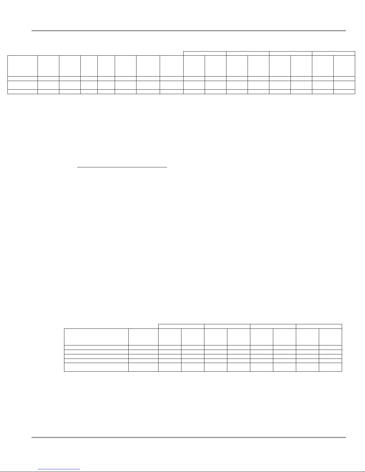
Appendix E: Accessories
2' (2 Filters) 3' (4 Filters) 4' & 5' (6 Filters) 6' (8 Filters)
Inlet
Concentration
10 ppm 0.15 Acetone 0.79 58.1 2% 40 hours 10 hours 135 g 171 ml 270 g 342 ml 405 g 513 ml 540 g 684 ml
10 ppm 0.20 Eth yl
10 ppm 0.22 Toluene 0.87 92.1 20% 240 hours 60 hours 1350 g 1552 ml 2700 g 3104 ml 4050 g 4656 ml 5400 g 6208 ml
Evap.
Rate
(ml/min)
Organic
Chemical
Acetate
SPGR MW
0.90 88.1 9% 120 hours 30 hours 608 g 675 ml 1216 g 1350 ml 1824 g 2025 ml 2432 g 2700 ml
Organic
Vapor
Adsorbed
Filter
Capacity
Estimated
Filter Life
Estimated
Check Life
Adsorbed
Weight
Adsorbed
Volume
Adsorbed
Weight
Adsorbed
Volume
Adsorbed
Weight
Adsorbed
Volume
Adsorbed
Weight
If the inlet concentration is decreased to 1 ppm, then the estimated filter life
will be increased by an average factor of 5. Likewise, if the inlet
concentration is increased to 25 ppm, then the estimated filter life will be
decreased by an average factor of 2. Experience with routine use will
establish a predictable filter life that is representative of your specific
chemical work.
Impregnated Carbon Filter Life
To estimate impregnated carbon filter life for acids, formaldehyde-formalin,
and ammonia, use the following chart below. The values in the chart below
are expressed in weight (grams) and volume (milliliters) which can be used to
estimate Filter Life from a known usage.
For example, you estimate that 37% hydrochloric acid is being used at 500
ml per week and want to know how to program the Filter Life timer for a 3'
Paramount. A 3' Paramount uses 40 pounds of impregnated carbon at 17%
estimated life before saturation. 17% of 40 pounds is equivalent to 3060
grams of available carbon. There are 424 g/L of hydrochloric acid in a 37%
solution. Thus, there are 3060 grams/424 g per L or 7.2 Liters (7200 ml) of
hydrochloric acid before saturation. Assuming there are 10 hours of use per
week at 500 ml per week, the expected Final Life is programmed at 140
hours and the Check Life is programmed at 40 hours and it comes from the
following calculation:
(7200 ml/500 ml/week) * 10 hours/week = 144 hours, rounded to 140 hours
Chemical
37% Hydrochloric Acid 17% 1530 g 3600 ml 3060 g 7200 ml 4590 g 10800 ml 6120 g 14400 ml
67% Nitric Acid 12% 1080 g 1150 ml 2160 g 2300 ml 3240 g 3450 ml 4320 g 4600 ml
96% Sulfuric Acid 11% 990 g 560 ml 1980 g 1120 ml 2970 g 1680 ml 3960 g 2240 ml
37% Formaldehyde or Formalin 10% 900 g 2250 ml 1800 g 4500 ml 2700 g 6750 ml 3600 g 9000 ml
50% Ammonia Solution
(Ammonium Hydroxide)
Impregnated
Carbon
Adsorbed
Filter Capacity
10% 990 g 1980 ml 1980 g 3960 ml 2970 g 5940 ml 3960 g 7920 ml
2' (2 Filters) 3' (4 Filters) 4' & 5' (6 Filters) 6' (8 Filters)
Adsorbed
Weight
Adsorbed
Volume
Adsorbed
Weight
Adsorbed
Volume
Adsorbed
Weight
Adsorbed
Volume
Adsorbed
Weight
Adsorbed
Volume
Adsorbed
Volume
Product Service 1-800-522-7658
69
Page 75

AAppppeennddiixx FF::
FFiillttrraattiioonn EEffffiicciieennccyy TTeesstt RReessuullttss
Ductless enclosures require filtration efficiency testing to validate performance.
Independent testing, conducted by a consultant and the University of Kansas,
concluded the tested filtration efficiency for acetone, ethanol, isopropyl alcohol,
toluene and hydrochloric acid was excellent. Filtration capacity is defined as a
percentage of the chemical mass adsorbed compared to the total carbon filter weight.
Utilizing analytical instrumentation, the organic vapor filter and acid vapor filter were
both independently tested for filtration efficiency. The solvents and acids listed below
were evaporated at both low and high evaporation rates. Low evaporation rates are
typical in ductless enclosures in order to maximize useful carbon filter life. Both
ethanol and acetone were specifically tested at low evaporation rates of 14ppm and
22ppm, respectively, to simulate real laboratory conditions of chemicals with low
filter capacities. High evaporation rates of 100-462ppm were used for most of the
organic solvents and mineral acid to accelerate the testing process of chemicals with
higher filtration capacity and determine filter saturation and chemical breakthrough.
The testing was designed to assess the filtration efficiency of the filters. As suggested
by carbon manufacturers, carbon filters usually have a 30 percent to 40 percent
filtration capacity of theoretical values for organic chemicals with higher carbon
affinity. The test results show a filtration efficiency of 33-39 percent for chemicals
with higher affinity for organic vapor carbon and directly in line with the 30-40
percent as suggested by carbon manufacturers. Since ethanol has very low filter
capacity, it is not alarming that the filtration efficiency is 17-19 percent; the test
results prove the practical matter of using low quantities of ethanol or any other
chemical with very lower filter capacity. The mineral acid filtration efficiency of
hydrochloric acid approached 83 percent of theoretical value and is attributed to the
chemisorption process of the treated acid filters. To conclude, the filtration efficiency
test data and charts indicate the ductless enclosure filtration was in line with carbon
manufacturer expectations and will provide a safe working environment for
controlled environments.
Exposure Evaporation No. of 3' Paramount Chemical Mass Detected Saturation Filtration Capacity Filtration
Chemical
Acetone 250 ppm 22 ppm 4 13500 grams 153 grams 1-2 ppm 1.1% 2.8% 39%
Ethanol or 1000 ppm 14 ppm 4 13500 grams 32 grams 6-9 ppm 0.3% 1.6% 19%
Ethyl Alcohol 1000 ppm 206 ppm 4 13500 grams 148 grams 6-9 ppm 1.1% 6.3% 17%
Isopropyl Alcohol 400 ppm 462 ppm 4 13500 grams 824 grams 8-11 ppm 6.1% 17.7% 34%
Toluene 100 ppm 155 ppm 4 13500 grams 1317 grams 0.5-1 ppm 9.8% 29.7% 33%
Limit Rate Filters Carbon Filter Mass Adsorbed Breakthrough Concentration Tested Theoretical Efficiency
37% Hydrochloric 5 ppm 100 ppm 4 18000 grams 2529 grams 0.5-1 ppm 14.1% 17.0% 83%
Acid of treated carbon
70
Product Service 1-800-522-7658
Page 76

Acetone
A
Appendix F: Filtration Efficiency Test Results
Exposure limit
250 ppm
Temp. 22° C
Hum. 41%
175 CFM
80 fpm face
verage evaporation
Evaporation by
heated container
rate 0.32 ml/min. 21.9
ppm inlet conc.
30# carbon 4x8
coconut shell
Test time 11.25 hrs.
400 ppm current TLV
PID detector
1-2 ppm
Breakthrough with
153 grams filtration
capacity
3' Paramount Model #6963300
SEFA 9 Method
Acetone (Reagent Grade) Test 9/10/08
Mass Adsorbed (grams) Acetone
0 20 40 60 80 100 120 140 160 180
3
2.5
2
1.5
1
0.5
Acetone Exhaust Concentration (ppm)
0
Product Service 1-800-522-7658
71
Page 77
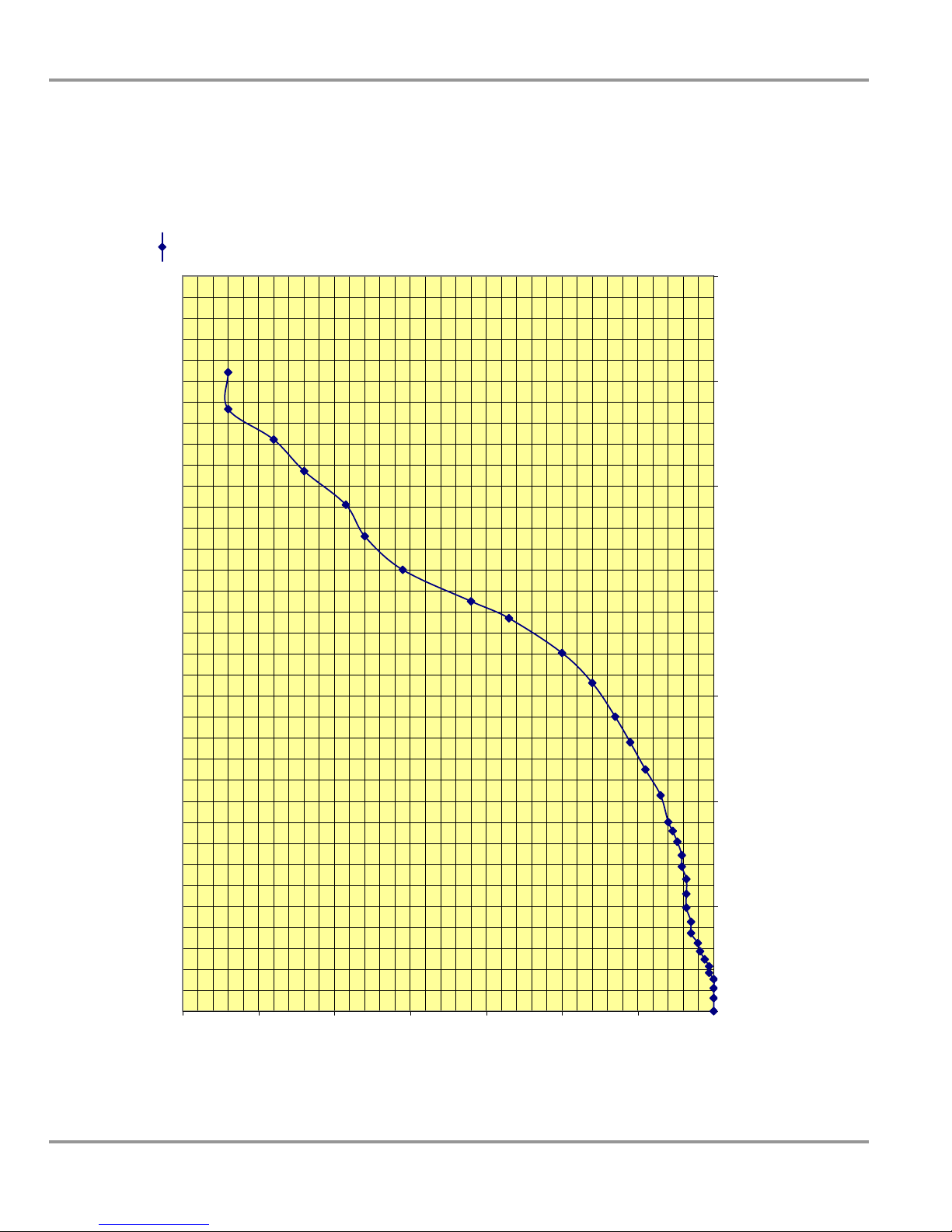
Appendix F: Filtration Efficiency Test Results
Ethyl Alcohol
or Ethanol
Exposure limit 1000
ppm
Temp. 20° C
Hum. 41%
175 CFM
80 fpm face
Evaporation by heated
verage evaporation
container
rate 2.44 ml/min. 206
ppm inlet conc.
30# carbon 4x8 coconut
shell
Test time 5.25 hrs.
1000 ppm current TLV
PID detector
6-9 ppm Breakthrough
with 148 grams filtration
capacity
SEFA 9 Method
3' Paramount Model # 6963300
Ethyl Alcohol (Reagent Grade) Test 10/01/08
72
Mass Adsorbed (grams)
0 100 200 300 400 500 600 700
140
120
100
80
60
40
Ethyl Alcohol Exhaust Concentration (ppm)
20
0
Product Service 1-800-522-7658
Page 78
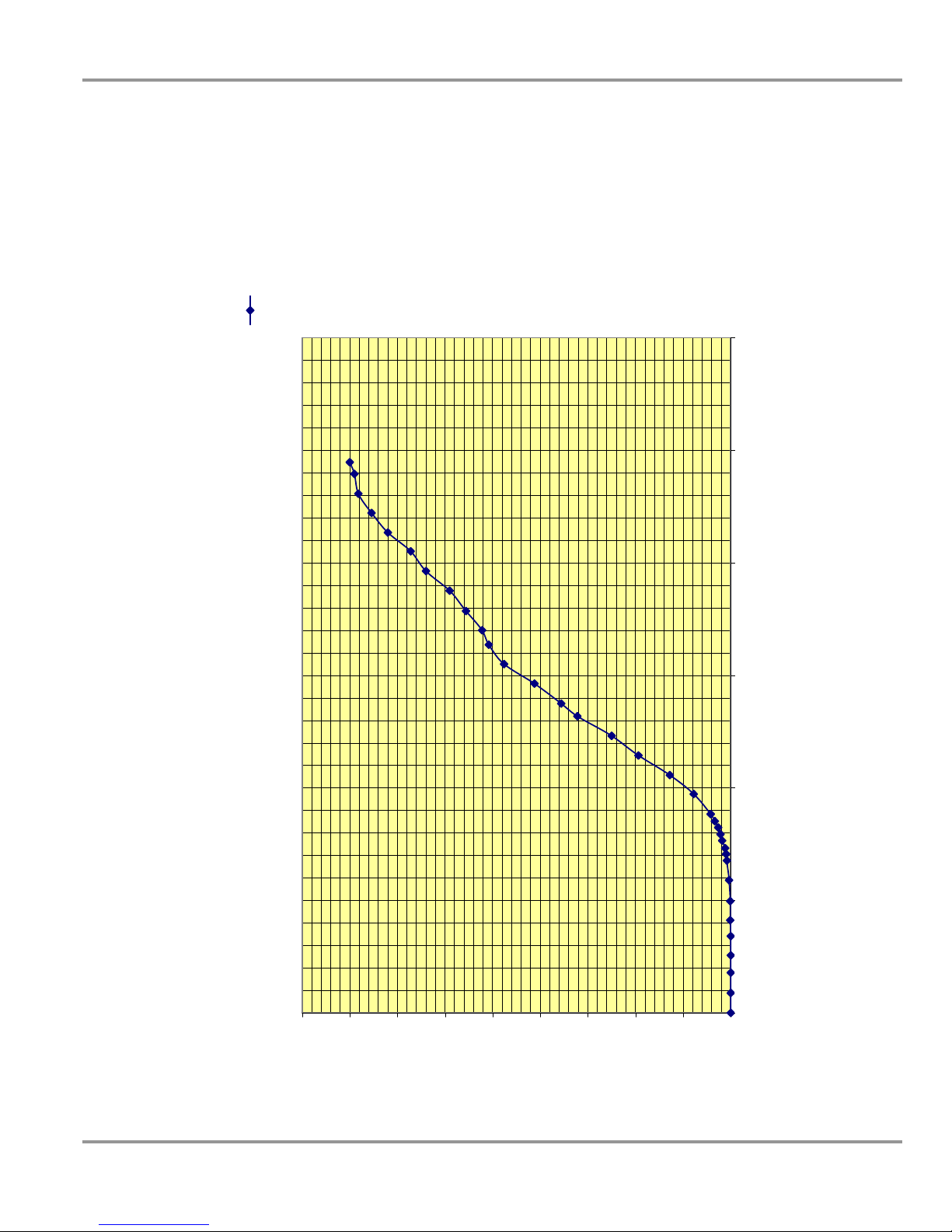
Appendix F: Filtration Efficiency Test Results
2-Propanol or
Isopropyl Alcohol
verage evaporation rate
7.13 ml/min. 462 ppm inlet
conc.
30# carbon 4x8 coconut
shell
Test time 7.15 hrs.
400 ppm current TLV
PID detector
8-11 ppm Breakthrough with
Exposure limit 400 ppm
Temp. 20° C
Hum. 41%
175 CFM
79 fpm face
Evaporation by heated
container
824 grams filtration capacity
SEFA 9 Method
3' Paramount Model # 6963300
2-Propanol (Reagent Grade) Test 9/16/08
400
450
350
300
Product Service 1-800-522-7658
Mass Adsorbed (grams) 2-Propanol
0 500 1000 1500 2000 2500 3000
100
250
200
150
50
2-Propanol Exhaust Concentration (ppm)
0
73
Page 79
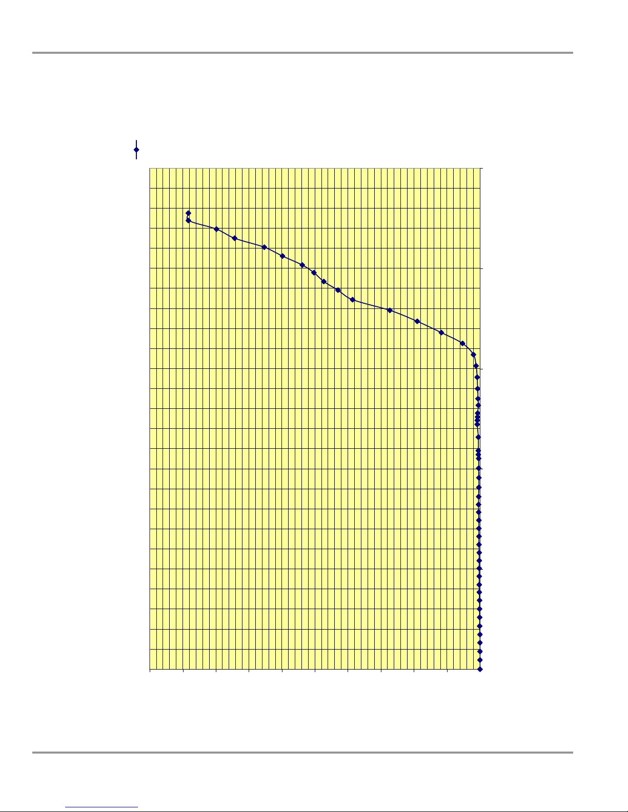
Appendix F: Filtration Efficiency Test Results
A
Toluene
Exposure limit 100
ppm
Temp.22 C
Hum. 40%
175 CFM
79 fpm face
Evaporation by
verage evaporation
heated container
rate 3.32 ml/min. 155
ppm inlet conc.
30# carbon 4x8
coconut shell
Test time 12.25 hrs.
100 ppm current TLV
PID detector
0.5-1 ppm
Breakthrough with
1317 grams filtration
capacity
3' Paramount Model # 6963300
Toluene (Reagent Grade) Test 9/23/08
SEFA 9 Method
Mass Adsorbed (grams) Toluene
0 500 1000 1500 2000 2500
100
90
80
70
60
50
40
30
20
Toluene Exhaust Concentration (ppm)
10
0
74
Product Service 1-800-522-7658
Page 80

HCL mass calculated as
100% HCL
Exposure limit 5 ppm
Appendix F: Filtration Efficiency Test Results
verage evaporation rate
1.72 ml/min 100 ppm inlet
conc.
40# carbon 4x8 coconut
shell impregnated
Test time 24.6 hrs.
5 ppm current TLV
Detection: Continous
monitoring of exhaust at
1.5 ml/min with acid gas
colorimetric tubes until
begin of color change, then
exhaust sample every 15-
30 minutes with HCL
colorimetric tubes 1-10
ppm.
0.5-1 ppm Breakthrough
with 2529 grams filtration
Temp. 20° C
Hum. 41%
175 CFM
79 fpm face
Evaporation by heated
container
capacity
3' Paramount Model # 6963300
HCL Acid Test 10/02/08
SEFA 9 Method
Mass Adsorbed (grams) HCL - Mass Calculated as 100% HCL
0 500 1000 1500 2000 2500 3000
4.5
4
3.5
3
2.5
2
1.5
HCL Exhaust Concentration (ppm)
1
0.5
0
Product Service 1-800-522-7658
75
Page 81

DECLARATION OF CONFORMITY
Application Council Directive(s): 73/23/EEC, 89/336/EEC, 2002/95/EC (ROHS),
2002/96/EC (WEEE), 2004/108/EC
Standard(s) to which conformity is declared: EN61010-1, EN61326-1, EN55022,
EN61000-3-2/3
Manufacturer’s Name: Labconco Corporation
Manufacturer’s Address: 8811 Prospect Avenue
Kansas City, MO 64132 USA
Importer’s Name: See Shipping/Customs Documents
Importer’s Address: See Shipping/Customs Documents for your equipment
Type of Equipment: Laboratory Equipment
Model No: Paramount Ductless Enclosures
69632 Series 2' Paramount
69633 Series 3' Paramount
69634 Series 4' Paramount
69635 Series 5' Paramount
69636 Series 6' Paramount
Serial No.: Various – See Individual Declaration
Year of Manufacture: 2008 and subsequent
I, the undersigned, hereby declare that the equipment specified above conforms to the
above Directive(s) and Standard(s).
See individual Declaration of Conformity which
will be signed by the importer for your country.
Place: _______________________________________
(Signature)
Date: _______________________________________
(Full Name)
_______________________________________
(Position)
Labconco P/N 36960-66, Rev. -, ECO E950
76
Product Service 1-800-522-7658
 Loading...