

Labconco Labconco-labconcoguardiandigitalmanual LABCONCO 1000 GUARDIAN DIGITAL MONITOR Operating and Instruction Manual

1
LABCONCO 1000
GUARDIAN DIGITAL MONITOR
Operating and Instruction Manual
Model: Guardian 1000 / 1
• Digital display
• 3 Relay inputs
• 3 Relay outputs
• Com port
Used for alarm indication and
monitoring on Fume Hoods
04/01/13
100 fpm
0 200fpm

2
Note :- Access to the Calibration and Configuration menus is password protected and is factory
set. To access and or change the password contact the supplier for the Engineers Password and
enter the Passwords in the Main Menu or alternatively use a Laptop connected to the Com port
and the Upload/Download software provided
OPERATOR DISPLAY PANEL
100 fpm
Velocity display fpm or m/sec
LED indicators
Function and up/down buttons
for Menu Configuration and
Calibration.
ENTER – also used as
Mute button for audible alarm
Velocity Bar Graph or
Alarm Time Line

3
Connection details :-
Notes :-
1. The Remote Interface Box is an optional extra. This is supplied
complete with a 2m long ribbon cable with IDC plugs. The box is
designed to allow termination of external cables rated at 220V and
includes the following connection points :-
3 – Input connections – Input 1 , Input 2 , Input 3
3 - Relay outputs - Output relays R1 , R2 , R3
2. Output 1 is an output giving a 0 –10 V DC signal proportional to the
Fume Hood face velocity over the range
of 0 – 200 fpm
3. BACnet and Modbus RTU included (optional terminal box required for
connection to the monitor).
REFER TO
INSTALLATION
INSTRUCTIONS
BEFORE
CONNECTING
www.tel-uk.com
Made in England
TEL
TO REMOTE
RELAY
INTERFACE BOX
I/P1
I/P3
I/P2
15V
PSU
I/P
-
+
0-10V
O/P
1
R1 R2
R3
INPUT 2
VOLT FREE RELAY
CONTACT INPUT
INPUT 1
VOLT FREE RELAY
CONTACT INPUT
120VAC POWER
SUPPLY
(15VDC Output)
SM6 AIRFLOW
SENSOR
RJ11 PLUG IN
CABLE (2M / 6’)
R1,R2,R3
VOLT FREE RELAY
OUTPUTS
Max 5A 250VAC / 30VDC
0-10V RETRANSMISSION
OUTPUT
PLUG IN COMS
CABLE (2M / 6’)
RS485 COM PORT Connector
Modbus RTU or BACnet
(OPTIONAL)
GND
(A)+
(B)-
+VE
To PC or BMS
To OTHER AFA1000
UNITS
-
sw
+
sw
+
+
sw
INPUT 3
SASH HIGH MICRO SWITCH or
PROXIMITY SWITCH
bl
bk
bn

4
1.1 General Description
All systems comprise of the following components :-
1 – SM6 Airflow Sensor,
1 – AFA1000 /1 Alarm unit,
1 – AC power supply
If the Sash Alarm System option is included there will also be a sash micro switch or proximity
switch.
Operator Features --- the alarm has the following operator features :-
Digital Display
The digital display is a back-lit, full graphic unit with a visual display of approx 56 x 27 mm.
The display operates through the software allowing the generation of figures, wording and Icons.
The display shows the fume cupboard face velocity in m/sec or fpm when enabled or the
alternative with no velocity reading but showing AIR FAIL / AIR SAFE as continuous display.
All of the above are configurable via the alarm key pad.
An ‘ event time line ’ segmented into 20 x 3 minute segments will scroll across the display
( when enabled) .This takes the form of a graphical ‘ blip’ that will progress from the right hand
side to the left hand side – representing events that have occurred during the past hour. On the
standard alarm this will be limited to airflow alarms but other alarms are available.
Using the diagnostics software and an associated computer via the com port on the alarm the
event data can be transferred to a data logger.
The alternative to the event time line is a dynamic ‘ bar graph ’ representing the face velocity
The display shows a Horn icon ( with line through it ) when the audible alarm is in the Muted
condition
Sash High – will be displayed when the Sash alarm is enabled and the sash is raised above
the max safe working opening.
This display will alternate on/off with the velocity reading.
Ext Alarm – will be displayed when the external alarm input is activated ( when enabled )
This display will alternate on/off with the velocity reading
Air Fail - will be displayed if the airflow is less than the Low air alarm point.
This display will alternate on/off with the velocity reading
High Air - will be displayed if the airflow is more than the High air alarm point.
This display will alternate on/off with the velocity reading
Set-back - will be displayed if the night set-back function is activated ( when enabled )
This display will alternate on/off with the velocity reading

5
Disabled - will be displayed if the alarm disable function is activated (when enabled)
This display will alternate on/off with the velocity reading
Close Sash - will be displayed if the sash is raised and the user is not present (when enabled)
This display will alternate on/off with the velocity reading
Additional features:
Mains Fail - will be displayed if the power fails to the monitor (when enabled)
*Note – this is an optional extra feature that requires an additional battery unit
Low Temp - will be displayed if the hood temperature drops below the low temp alarm point
(when enabled) This display will alternate on/off with the velocity reading
*Note – this is an optional extra feature that requires an additional temperature
sensor
High Temp - will be displayed if the hood temperature rises above the high temp alarm point.
(when enabled) This display will alternate on/off with the velocity reading
*Note – this is an optional extra feature that requires an additional temperature
sensor
LED Indicators ---- the alarm unit has three LED indicators :-
Red -- Alarm
Amber -- Caution
Green -- Safe
Audible Alarm sounder -- the alarm has an audible alarm sounder with local or remote
Mute facility
Enter --- the alarm has an Enter button -- this is multi-functional as follows :-
Press Enter momentarily when alarm is sounding will mute the alarm
Press Enter for 5 secs will gain access to Calibration and Configuration
menus ( both menus password protected )
+ / - -- the alarm has + / - buttons that can be used to scroll through the calibration and
configuration menu or to select options or values

6
External Connections -- the alarm unit will have the following connection points :-
Input 1 --- volt free relay input configurable for normally closed or normally open relays
This input can be configured as :-
Alarm disable
Night set-back
External alarm
Sash High
Mains Fail
Sash Warning
High / Low
Temperature
Input 2 --- volt free relay input configurable for normally closed or normally open relays
This input can be configured as :-
Alarm disable
Night set-back
External alarm
Sash High
Mains Fail
Sash Warning
High / Low
Temperature
Input 3 --- volt free relay input configurable for normally closed or normally open relays
This input can be configured as :-
Alarm disable
Night set-back
External alarm
Sash High
Mains Fail
Sash Warning
High / Low
Temperature
Output 1 --- volt free relay output configurable as normally closed or normally open relays.
Output 2 --- volt free relay output configurable as normally closed or normally open relays.
Output 3 --- volt free relay output configurable as normally closed or normally open relays.

7
Com Port --- to enable connection to Laptop or PC for full diagnostics , logging or setting
up and for communications to building computer system ( BMS)
Power supply --- low voltage DC power supply
Airflow Sensor --- connection socket for the face velocity airflow sensor.
See AFA Coms Manual document for other specific information on Modbus RTU and BACnet
options and settings.

8
1.2 Alarm Configuration / Calibration
The alarm can be configured via a Laptop or PC using a variety of ‘set up ’ programs each
designed for a particular application with a combination of inputs , outputs and push buttons.
This configuration can be changed via the alarm key pad using the menu system if required or
re-configured by re-connection of the laptop or PC.
This allows the fume hood manufacturer to stock standard units and configure the alarms
to suit the application.
The configuration of the various functions and the calibration of the alarm face velocity display is
menu driven. Access to the menu will be via password ( 4 digit number ) and will be two level.
The first level will be for calibration of the unit and the second level will be for ‘engineers’ to set
up the configuration of the alarm.
NOTE:- If you enter the Calibration or Configure Menu by accident :-
press the + & - buttons at the same time to escape back to the Main Menu
The menus and sub–menus are in ‘ plain language ’ and incorporate brief instructions where
appropriate.
See menu operation document
1.3 Start up
When unit is powered up the following sequence of events occur :-
1. The 12V DC power is applied to the airflow sensor and a delay on timer ( 30 sec ) is initiated.
2. The alarm then performs a self test on the display and all indicators etc ( approx 5 sec )
3. The display show a ‘ Welcome note ’ – with the fume cupboard manufacturer company name
( if configured ) for the rest of the initial 30 sec delay time. During this time the airflow
sensor is stabilising
4. During the whole of the 30 sec period all alarms and relay outputs are inhibited.
5. At the end of the 30 sec delay the unit performs one of two options :-
a. If the alarm calibration has been previously completed – the unit goes to
normal operating mode ( Run )
b. If the unit has not been calibrated the unit displays
‘ Unit requires Set up -- press Enter to access Set up menu ’
The set up menu allows calibration or configuration via the password protection
During the set-up all alarms and output relays are inhibited.

9
1.4 Events / actions
Safe airflow
• Meter reading above warning level ( e.g. > 90fpm )
• Green LED on
Warning airflow
• Meter reads between warning level and air fail level ( e.g. > 80fpm and < 90fpm )
• Amber LED on
Low airflow
• Meter reads below alarm level for longer than the warning to low air delay time
• AIR FAIL toggles on / off with display
• Red LED on ( Flashing )
• Audible alarm sounds -- can be muted via Enter pushbutton
• Low air relay operates ( if configured )
Reset : -- when airflow rises 4fpm above Low air level for longer than the low air to
warning air delay time the Low air alarm resets automatically
High airflow
If configured :-
• High Air toggles on / off with display
• Audible alarm sounds – can be muted via Enter pushbutton)
• High air relay operates ( if configured )
Audible alarm Mute
• When the audible alarm is muted via the Enter button - an Icon ( horn with forward slash) is
shown on the display.
Sash High
• When the input configured as Sash High is activated
• Amber LED on
• Sash High – toggles on / off with velocity display

10
• Audible alarm sounds
• Audible can be muted via Enter pushbutton -- this silences the alarm and initiates a repeat
timer ( if configured ). After the delay time the alarm re-sounds ( and can be re-muted).
During this time the Amber LED flashes on / off.
• Sash High relay operates ( if configured )
Reset when Sash lowered to safe position and input de-activated.
High / Low
• When input configured as High/Low is activated
• Display Icon shows High or Low
• High / Low relay operates ( if configured )
This function is designed for two speed fan operation or two position damper operation switched
via a micro switch or proximity switch activated at a given position on the sash.
Night set-back
• When input configured as Night set-back is activated
• Night set-back Icon is displayed
• Red LED on ( Flashing)
• Reduced Low air alarm ( if configured )
• Audible alarm muted
• Mute Icon shown on display
External alarm
• When input configured as External alarm is activated
• Red LED on ( Flashing) – ( if configured )
• External Alarm toggles on /off with display -- ( if configured )
• Audible alarm sounds – can be muted via Enter pushbutton
• External alarm relay operates ( if configured)
Alarm disable
• When input configured as Alarm disable is activated
• Alarm disabled is displayed
• Red LED on ( Flashing)
• Audible alarm muted
• Mute Icon shown on display

11
Close Sash
• When input configured as Close Sash is activated
• Red LED on
• Close Sash toggles on /off with display
• Audible alarm sounds (after pre-set time)
• Audible can be muted via Enter pushbutton -- this silences the alarm if configured.
Mains Fail (Optional)
• When the input configured as Mains Fail is activated
• Red LED on
• Mains Fail is displayed
• Audible alarm sounds
• Audible can be muted via Enter pushbutton -- this silences the alarm if configured.
Reset when Mains power is provided to monitor
Temperature (Optional)
• When input configured as Temperature is activated (and temp sensor connected)
• Temperature and Airflow displayed – Temp display can be disabled.
• High Temp toggles with Airflow display - Red LED on (Constant) with Audible alarm
• Low Temp toggles with Airflow display - Red LED on (Constant) with Audible alarm

12
2.1 Quick Start Installation
Follow the instructions below for installing and commissioning the unit. :-
1. The Fume Hood comes prepared to accept the Digital 1000 airflow alarm system.
2. First, remove the front panel by lifting it straight up and out away from the hood.
3. Next, remove the cover plate located at the top of the right corner post.
4. Install the monitor to the upper right corner post using the two screws that came with
your kit. See figure 1.
5. The connection of the air sensor, adaptor and hose will follow next.
a. Connect one end of the supplies sidewall adaptor with nut included in your kit by
removing the uppermost plastic plug from the ½” hole in the sidewall of the hood and
replacing it with the adaptor and nut. The nut is located inside the fume hood. See
figure 2.
b. Cut 1.5” of the white hose (1.0” OD x .79” ID) supplied with your monitor. Connect
one end of the hose to the sidewall adaptor. See Figure 2.
c. Connect the square air sensor to the other end of the white hose and be sure to
connect the sensor cable from the air sensor to the back of the monitor. This
completes the airway connection per Figure 2.
6. In your kit you will find an electrical cover plate and snap-in electrical outlet. Snap the
outlet in place making sure the outlet is secure.
7. Next, remove and discard the electrical cover plate that is on the junction box at the top
of your hood.
8. Wire in the cover plate that you just prepared to the existing wires inside of the hood
junction box per the wiring diagram on top of the fume hood. WARNING: make sure
that the power is disconnected to your hood prior to connecting the new cover plate.
9. Secure the cover plate to the junction box with the existing screw.
10. Plug the output cord of the power supply to the back of the monitor and plug the power
supply into the outlet on the cover plate of the junction box.
11. Replace the front panel and calibrate your unit according to the following instructions –
step 2.1. For additional calibration guidelines follow the steps listed in section 2.4

13
Figure 1

14
Figure 2
Nut, mounted on inside of
fume hood sidewall
Adapter
Hose
Sensor

15
2.2 Calibration :-
1. Power up the unit and wait at least 30 secs while the sensor temperature stabilises.
2. If the unit has not been calibrated the unit will display ‘ Requires setup ’ – press ENTER
to continue and in the Main Menu use the +/- buttons on the alarm facia select ‘ SETUP ‘
and then press the ENTER button.
3. In the Setup Menu select ‘CALIBRATION’ and press the ENTER button
4. At this stage you will be requested to enter the PASSWORD. Use the +/- buttons to select
the individual digits in turn and then press ENTER.
If the password is correct the unit will go to the calibration mode. If the password is not
correct you will be requested to try again --- on the third wrong password entry the
calibration menu will lock out for 10 mins
5. When in the calibration mode follow the instructions on the display screen to carry out
the calibration of the unit. See ‘Calibration Notes’ below for hints on successful
calibration.
When the calibration is complete the unit will return to the Main Menu.
6. Use the +/- buttons on the alarm facia select ‘ RUN ’ and then press the ENTER button.
The unit will now function and display the measured Fume Hood face velocity
2.3 Calibration Notes :-
1. When using a standard Fume Hoods with Vertical Sliding sashes open the sash to the
normal max safe working height for the Low Air sample.
2. For the Higher Air sample close the sash to approx 50% of the opening used for the
Lower Air sample. If the Higher air sample value is too close to the Lower Air sample the
alarm will detect this and ask you to repeat with a higher value. To do this close the sash
a little more and repeat the sample. Avoid closing the sash below 100mm/4 inches.
3. The face velocity readings on the open sash may vary at different points on the measuring
grid by up to 20fpm. This is quite acceptable in terms of the fume cupboard performance
so long as no individual point is below the designated Low Air alarm point .The figure
entered for the calibration point can be taken as the average value of all the measuring
grid readings or could be taken as the individual lowest point on the grid. For most fume

16
hoods this low point is on the bottom row in the centre and is a convenient position to
measure and for future reference when checking the alarm during annual maintenance.
4. Take time when measuring the face velocities for the calibration procedure to allow for
the velocities across the open sash to stabilise. If the velocities are changing or are
turbulent during the sampling period the alarm will detect this and ask you to repeat the
sample.
5. When using a Fume Hood with Horizontal Sliding sashes open the sashes to the normal
max safe working opening for the Low Air sample.
6. When calibrating or re-calibrating the alarm it is important to ensure that the Adapter and
hose is connected to the SM6 sensor on the fume hood as per figure 2. If the Adapter and
hose is not connected the sensor will not ‘see’ a change in the airflow during the
calibration procedure and when switched to the Run condition the display will show a
fixed reading that will not change when the fume cupboard velocity changes. This only
applies during the calibration mode. If in normal running after successful calibration the
vent kit becomes disconnected the air flow across the sensor will fall and the alarm will
go into the AIR FAIL condition.
2.4 Calibration Guidelines :-
1. Calibrate the airflow monitor according to the instructions in set 2.1. To successfully
calibrate the monitor, it will be necessary to change the face velocity by moving the sash
position. Typical calibration conditions are set to face velocity air sample differences of
at least 20 feet per minute. The airflow monitor is factory set to be calibrated with a
difference of at least 50 fpm and can be changed by changing the “lower/higher air
sample difference”. The following suggested in flow face velocity speeds are
recommended to successfully calibrate. Typical low air alarms are set 10-20 fpm below
operation speeds. Follow step 2 below.
Low Air
Alarm Set
Point
Hood
Operating in
Flow Speed
Low
Calibration
Set Point
High
Calibration
Set Point
40 – 50 fpm
60 fpm
40 – 60 fpm
100 – 120 fpm
60 – 70 fpm
80 fpm
50 – 90 fpm
100 – 150 fpm
80 – 90 fpm
100 fpm
50 - 110 fpm
100 – 170 fpm

17
1. Go to SETUP and then CONFIGURE, then go to CAL CONFIG MENU and change the
“lower/higher air sample difference” to 20 fpm. This will allow you to successfully
calibrate with values of a minimum of 20 fpm difference.
2. While in CAL CONFIG MENU, change the “sensor difference” from 10% to 3%.
3. While in CAL CONFIG MENU, adjust the red low air alarm to the desired setting such
as 60 fpm. Then adjust the yellow “CAUTION or WARNING” to 63 fpm. Then adjust
the “CAUTION or WARNING” air reset to 3 fpm. This sets the alarm condition and can
be altered as desired.
4. To complete the CAL CONFIGURATION, be sure to enter “DONE”.
5. To start the calibration mode, use the Labconco 1000 Manual and enter
“CALIBRATION” mode on the display from the SETUP menu.
6. Follow the instructions on the display and alter the low face velocity by altering the sash
position to its most open position. Measure the average face velocity and enter the low
value on the display. Be careful not to block the opening. The low exhaust velocity
calibration will take about 5 seconds.
7. Now alter the high exhaust velocity by altering the sash position to a lower open position.
Measure the average face velocity and enter the high value on the display. The high
value must be at least 20 fpm greater than the low value. The high exhaust velocity
calibration will take about 5 seconds.
8. Be sure to enter “DONE” after successfully completing the low and high calibration set
points.
9. Once calibration is completed go to “RUN” and hit “ENTER”. The value should read
close to the high calibration set point where the sash was left in its last position.
10. Recheck the face velocity with an anemometer to confirm the display on the digital
airflow monitor at various sash positions.

18
3.0 Monitor Configuration :-
The Airflow monitor menu contains a parameter group called “ Cal Configure” that
contains all of the parameter settings that may need to be adjusted to complete a
successful calibration. The following list shows the parameters and their functions. Refer
to the full parameter list in section 6.0 to see the default factory settings.
To access the Cal config menu – (From Run screen) Press Enter for 5
secs/Setup/Configure/Password (000)/Cal Config.
1. Display Units – Face velocity display units – fpm or m/sec.
2. Low Air Alarm – Sets the low air alarm velocity value – typically 70-80% of the
design velocity.
3. Low Air Cut Off - When enabled inhibits the face velocity reading from being
displayed below the selected value – for example, Low Air Cut Off enabled and set to
30fpm, the display will stop reading velocity below 30fpm. This function is useful in
situations where the hood blower is switched off and there is still a flow through the
hood either from positive room pressurization or from other influences and the
monitor is not required to display velocity. Typically set to a low value e.g. 30 fpm.
4. Warning Air Alarm – Sets the warning air alarm velocity value – typically 80-90%
of the design velocity.
Warning Air Reset – Sets the reset differential value – this is the value that the
monitor resets into Air Safe above the Air Fail alarm point on rising airflow.
5. High Air Alarm – Enables and sets the high air alarm velocity value – typically not
used.
6. Low Air Fluctuations – This parameter monitors the fluctuations in airflow during
the low air calibration point. The monitor samples the airflow for 5 seconds and
averages the airflow readings, if any of the fluctuations different from the average by
more than the parameter value the calibration will be stopped and a “Fluctuations too
high” message will be shown with option of retry or cancel calibration.
7. High Air Fluctuations – This parameter monitors the fluctuations in airflow during
the second air calibration point. The monitor samples the airflow for 5 seconds and
averages the airflow readings, if any of the fluctuations different from the average by
more than the parameter value the calibration will be stopped and a “Fluctuations too
high” message will be shown with option of retry or cancel calibration.
8. Low High Diff – This parameter sets the difference required between airflow
samples during calibration. If the value entered during the second calibration point
too low a “Low High Diff too low” message will appear and the calibration will be
stopped.

19
9. Warning - Alarm Time – This parameter sets a time delay for the Low Air alarm to
activate once the Low Air alarm point have been reached. This is to stop the airflow
from dropping in and out of Low Air Alarm if the airflow is turbulent and is close to
the low air alarm point value.
10. Alarm – Warning Time – This parameter sets a time delay for the air to reset to Air
Safe once the Warning air point have been reached. This is to stop the airflow from
dropping in and out of Low Air Alarm if the airflow is turbulent and is close to the
low air alarm point value.
11. Show Air Flow – This parameter enables / disables the face velocity reading on the
display. When disabled the monitor will show ether “Air Safe” or Air Fail”.
12. Show Time Line – This parameter enables / disables the time line. When disabled
the velocity bar graph (0-200fpm) is shown at the top of the display window. When
enabled a time line showing the airflow alarm condition for the previous 60 mins will
be shown at the top of the display window.
13. Audible Alarm – This parameter enables / disables the audible alarm. When disabled
the audible alarm will not sound in any alarm condition.
14. Sensor Difference – This parameter looks at the actual change on the sensor output
between the 2 cal points to make sure that the sensor sees enough change to allow the
calibration. If the monitor does not see enough change a “Sensor diff too low – Check
sensor” message will appear. This value can be lowered and then the monitor can be
recalibrated. This parameter is useful to ensure that the hose has been connected.
15. Sensitivity – This parameter reduces the scale of the monitor so that the change in
sensor output has a lesser effect on the change in the airflow display. Reducing the
sensitivity will reduce the airflow reading at higher airflows so should only be done
in small adjustments – typically 5%.

20
Dimensions
88mm
3.46”
74mm
2.91”
100
fpm
148mm
5.83”
Panel Cutout
Dimensions
118mm
(4.65!)
126mm
(4.96!)
80mm
(3.15!)
74mm
2.91”
10mm
0.39”
17mm
0.67”
74mm
2.91”
12mm
0.47”
20mm
0.79”
25mm
1”
25mm
1”
27mm
1.06”
12mm Dia.
for
SM6 cable
30mm
Sensor Hole for
Vent Tube
SM6
Sensor
Dimensions
( Rear view )
SM6 Sensor Panel
Cutout
Dimensions
( Front view )
NOT TO SCALE
2 x Holes for self tapping fixing
screw.
(4mm Fixing Hole provided on
SM6 sensor)
12mm
0.47”
10mm
0.39”
2 x Fixing Holes
(Plate Hole size 0.157”)

21
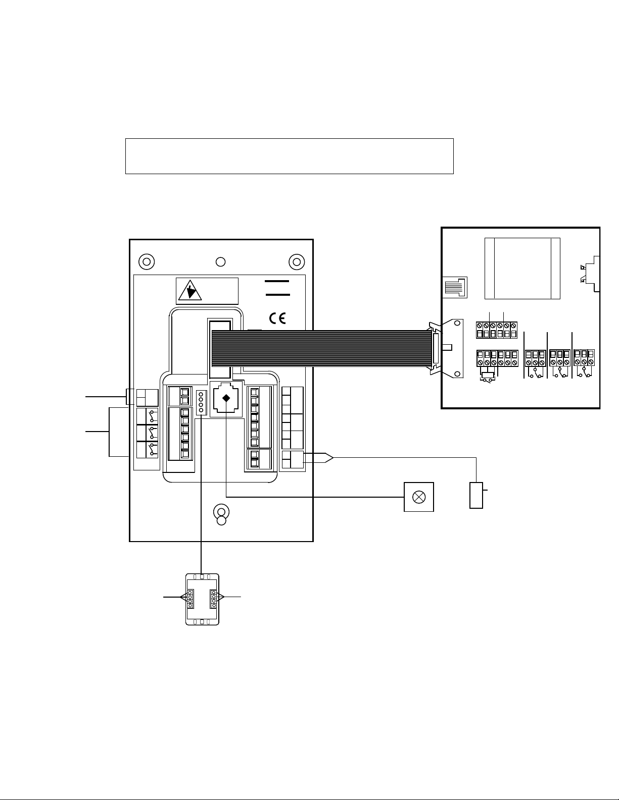
5.0 Typical Wiring Diagram --- (Alarm only)
Notes :
Output 1 is an output giving a 0 –10 V DC signal
proportional to the Fume Hood face velocity over the range of
0 – 200 fpm.
BACnet and Modbus RTU coms are included – an optional
terminal box is required for connection to the monitor.
See AFA Coms Manual document for other specific information on Modbus
RTU and BACnet options and settings.
REFER TO
INSTALLATION
INSTRUCTIONS
BEFORE
CONNECTING
www.tel-uk.com
Made in England
TO REMOTE
RELAY
INTERFACE BOX
I/P1
I/P3
I/P
15V
PSU
-
+
010V
INPUT 2
VOLT FREE
RELAY CONTACT
INPUT
INPUT 1
VOLT FREE
RELAY CONTACT
INPUT
120VAC POWER
SUPPLY
(15VDC Output)
SM6
AIRFLOW
RJ11 PLUG IN
CABLE (2M /
R1,R2,R3
VOLT FREE RELAY
OUTPUTS
Max 5A 250VAC / 30VDC
0-10V RETRANSMISSION
OUTPUT
PLUG IN
COMS CABLE
RS485 COM PORT
Connector
GND
(A)+
(B)-
To PC or BMS
To OTHER AFA1000
UNITS
-
sw
sw
+
sw
+
-
INPUT 3
SASH HIGH MICRO SWITCH or
PROXIMITY SWITCH
bl
bk
bn

22
5.1 Typical Wiring Diagram with Optional Temperature Sensor
Note :
Temp Sensor Optional
Temp sensor connects to Input 3.
Input 3 has to be set to analogue and function set to Temperature.
REFER TO
INSTALLATION
INSTRUCTIONS
BEFORE
CONNECTING
www.tel-uk.com
Made in England
TEL
TO REMOTE
RELAY
INTERFACE BOX
I/P1
I/P3
I/P2
15V
PSU
I/P
-
+
0-10V
O/P
1
R1 R2
R3
INPUT 2
VOLT FREE RELAY
CONTACT INPUT
INPUT 1
VOLT FREE RELAY
CONTACT INPUT
TEMPERATURE
SENSOR
120VAC POWER
SUPPLY
(15VDC Output)
SM6 AIRFLOW
SENSOR
RJ11 PLUG IN
CABLE (2M / 6’)
R1,R2,R3
VOLT FREE RELAY
OUTPUTS
Max 5A 250VAC / 30VDC
0-10V RETRANSMISSION
OUTPUT
(OPTIONAL)
PLUG IN COMS
CABLE (2M / 6’)
RS485 COM PORT Connector
Modbus RTU or BACnet
(OPTIONAL)
GND
(A)+
(B)-
+VE
To PC or BMS
To OTHER AFA1000
UNITS
bk
gn
red
-
sw
+
sw
+
sw
+
-
23
5.2 Typical Wiring Diagram with Optional Relay Interface Unit
Optional Relay Interface Unit in ABS enclosure mounted on top of Fume Hood to
allow up to external cable connections to be terminated.
Rated at 220V 5A
REFER TO
INSTALLATION
INSTRUCTIONS
BEFORE
CONNECTING
www.tel-uk.com
Made in England
TEL
TO REMOTE
RELAY
INTERFACE BOX
I/P1
I/P3
I/P2
15V
PSU
I/P
-
+
0-10V
O/P
1
R1 R2
R3
120VAC POWER
SUPPLY
(15VDC Output)
SM6 AIRFLOW
SENSOR
RJ11 PLUG IN
CABLE (2M / 6’)
R1,R2,R3
VOLT FREE RELAY
OUTPUTS
Max 5A 250VAC / 30VDC
0-10V RETRANSMISSION
OUTPUT
PLUG IN COMS
CABLE (2M / 6’)
RS485 COM PORT Connector
Modbus RTU or BACnet
(OPTIONAL)
GND
(A)+
(B)-
+VE
To PC or BMS
To OTHER AFA1000
UNITS
-
sw
+
sw
+
sw
+
-
R3
R2
R1
Sash High
I/P3
0-10
o/p 2
+V
-V
sw
I/P1 I/P2
0 24v 0-10v
Volt Free Relays
(10A 120VAC AC1)
Econ
O/P
14 WAY RIBBON CABLE
RELAY INTERFACE UNIT

24
6.0 Parameter list / factory settings.
AFA10001/Mk2 Labconco
FILE NUMBER : 1.6
TYPE : AFA1000/1Mk2
CUSTOMER : Labconco
The AFA1000 monitor has been factory set to the listed parameter settings. To change
any parameter setting press and hold the enter button until the "Main Menu" screen is
displayed, select "Configure" to view the parameters and use the +/- and Enter buttons
to change the settings.
FOR FULL INSTALLATION / CALIBRATION / CONFIGURATION DETAILS PLEASE
REFER TO THECALIBRATION SECTION OF THE USER MANUAL.
FACTORY DEFAULTS
Menu
Units
Default Settings
Configuration Menu: -
Calibration Config
ON
DISPLAY UNITS
M/SEC
FPM
FPM
ON
LOW AIR ALARM
FPM
60
ON
LOW AIR CUTOFF
OFF ON
ON
ON
CUTOFF VELOCITY
FPM
30
ON
WARNING AIR ALARM
FPM
63
ALARM TO WARNING AIR HYSTERESIS
FPM
3
ON
HIGH AIR ALARM
ENABLED
DISABLED
DISABLED
ON
HIGH AIR ALARM
FPM
ON
LOWER AIR SAMPLE FLUCTUATIONS
%
5
ON
HIGHER AIR SAMPLE FLUCTUATIONS
%
10
ON
LOWER/HIGHER AIR SAMPLE DIFFERENCE
FPM
30
ON
WARN TO ALARM AIR TIME
SECONDS
30
ON
ALARM TO WARN AIR TIME
SECONDS
1
ON
SHOW AIR FLOW
ENABLED
ENABLED
DISABLED
ON
SHOW TIME LINE
ENABLED
DISABLED = SHOW BAR GRAPH
DISABLED
ON
AUDIBLE ALARM
ENABLED
ENABLED
NOT ENABLED
ON
SENSOR DIFFERENCE
%
10
ON
SENSITIVITY
%
100
Configuration Menu

25
OFF
TEMPERATURE*
TEMP UNITS – oC / oF
C
(*Requires optional Temp sensor)
LOW TEMP ALARM
0.0 C
HIGH TEMP ALARM
50.0 C
SHOW TEMP – Enabled/Disabled
DISABLED
ON
INPUT 1
NOT ACTIVE
ACTIVE ON CLOSING CONTACT
ACTIVE ON CLOSING CONTACT
ACTIVE ON OPENING CONTACT
ANALOGUE
ON
INPUT 1 – FUNCTION
NONE
ALARM DISABLE
NIGHT SET-BACK
NIGHT SET-BACK
EXTERNAL ALARM
SASH HIGH
HIGH / LOW
SASH WARNING
TEMPERATURE
ON
INPUT 2
NOT ACTIVE
NOT ACTIVE
ACTIVE ON CLOSING CONTACT
ACTIVE ON OPENING CONTACT
ANALOGUE
ON
INPUT 2 - FUNCTION
NONE
NONE
ALARM DISABLE
NIGHT SET-BACK
EXTERNAL ALARM
SASH HIGH
HIGH/LOW
SASH WARNING
TEMPERATURE
ON
INPUT 3
NOT ACTIVE
ACTIVE ON CLOSING CONTACT
ACTIVE ON CLOSING CONTACT
ACTIVE ON OPENING CONTACT
ANALOGUE
ON
INPUT 3 - FUNCTION
NONE
ALARM DISABLE
NIGHT SET-BACK
EXTERNAL ALARM
SASH HIGH
SASH HIGH
HIGH/LOW
SASH WARNING
TEMPERATURE
ON
OUTPUT RELAY 1 ACTIVATION
CONTACT CLOSES ON ACTIVATION
Contact closes on activation
CONTACT OPENS ON ACTIVATION
ON
OUTPUT RELAY 2 ACTIVATION
CONTACT CLOSES ON ACTIVATION
Contact closes on activation
CONTACT OPENS ON ACTIVATION
ON
OUTPUT RELAY 3 ACTIVATION
CONTACT CLOSES ON ACTIVATION
Contact closes on activation

26
CONTACT OPENS ON ACTIVATION
ON
LOW AIR ALARM - RELAY
NONE
OUTPUT RELAY 1
RELAY 1
OUTPUT RELAY 2
OUTPUT RELAY 3
ON
DISABLE ALARM - RELAY
NONE
NONE
OUTPUT RELAY 1
OUTPUT RELAY 2
OUTPUT RELAY 3
ON
SASH HIGH REPEAT TIMER
ON
ON
OFF
ON
SASH REPEAT TIME
MIN
5
ON
SASH HIGH RELAY
NONE
NONE
OUTPUT RELAY 1
OUTPUT RELAY 2
OUTPUT RELAY 3
ON
HIGH / LOW RELAY
NONE
NONE
OUTPUT RELAY 1
OUTPUT RELAY 2
OUTPUT RELAY 3
ON
NIGHT SET-BACK
MAINTAIN LOW AIR ALARM
Maintain Low Air alarm
REDUCE LOW AIR ALARM
ON
NIGHT SET BACK REDUCED ALARM
FPM
49
ON
NIGHT SET-BACK RELAY
NONE
NONE
OUTPUT RELAY 1
OUTPUT RELAY 2
OUTPUT RELAY 3
ON
EXTERNAL ALARM - LED
ON OFF
OFF
ON
EXTERNAL ALARM - DISPLAY ICON
ON
OFF
OFF
ON
EXTERNAL ALARM - RELAY
NONE
NONE
OUTPUT RELAY 1
OUTPUT RELAY 2
OUTPUT RELAY 3
OFF
LOW TEMP RELAY
NONE
NONE
OUTPUT RELAY 1
OUTPUT RELAY 2
OUTPUT RELAY 3
OFF
HIGH TEMP RELAY
NONE
NONE
OUTPUT RELAY 1
OUTPUT RELAY 2
OUTPUT RELAY 3
ON
SENSOR ERROR OPTIONS
SOUNDER ON
ON
SOUNDER OFF
SENSOR ERROR RELAY
NONE
NONE
OUTPUT RELAY 1

27
OUTPUT RELAY 2
OFF
SASH WARNING TIMER
MINS
0
OUTPUT RELAY 3

28
7.0 LIMITATION OF WARRANTY AND LIABILITY
Seller warrants that this product, under normal use and service as described in the operator’s manual shall be
free from defects in workmanship and material for a period of twelve (12) months, or the length of time specified
in the operator’s manual, from the date of shipment to the customer. This limited warranty is subject to the
following exclusion :-
a. Batteries and certain other components when indicated in specifications are warranted for a period of
90 days from the date of shipment to the customer.
b. With respect to any repair services rendered, Seller warrants that the parts repaired or replaced will
be free from defects in workmanship and material, under normal use, for a period of 90 days from the
date of shipment to the customer
c. Seller does not provide any warranty on finished goods manufactured by others. Only the original
manufacturer’s warranty applies.
d. Unless specifically authorised in a separate writing by Seller, Seller makes no warranty with respect
to, and shall have no liability in connection with, any goods which are incorporated into other
products or equipment by the Buyer. All goods returned under warranty shall be at the Buyer’s risk of
loss, Seller’s factory prepaid, and will be returned at Seller’s risk of loss, Buyer’s factory prepaid.
The foregoing is IN LIEU OF all other warranties and is subject to the conditions and LIMITATIONS stated herein. NO
OTHER EXPRESS OR IMPLIED WARRANTY OF FITNESS FOR PARTICULAR PURPOSE OR MERCHANTABILITY IS
MADE.
THE EXCLUSIVE REMEDY OF THE USER OR PURCHASER, AND THE LIMIT OF LIABILITY OF SELLER FOR ANY
AND ALL LOSSES, INJURIES, OR DAMAGES IN CONNECTION WITH THIS PRODUCT ( INCLUDING CLAIMS BASED
ON CONTRACT NEGLIGENCE, STRICT LIABILITY, OTHER TORT, OR OTHERWISE ) SHALL BE THE RETURN OF
THE PRODUCT TO THE FACTORY OR DESIGNATED LOCATION AND THE REFUND OF THE PURCHASE PRICE,
OR, AT THE OPTION OF THE SELLER, THE REPAIR OR REPLACEMENT OF THE PRODUCT. IN NO EVENT SHALL
SELLER BE LIABLE FOR ANY SPECIAL, INCIDENTAL OR CONSEQUENTIAL DAMAGES.SELLER SHALL NOT BE
RESPONSIBLE FOR INSTALLATION, DISMANTLING, REASSEMBLY OR REINSTALLATION COSTS OR CHARGES.
NO ACTION, REGARDLESS OF FORM, MAY BE BROUGHT AGAINST THE SELLER MORE THAN ONE YEAR AFTER
THE CAUSE OF ACTION HAS ACCRUED.
The purchaser and all users are deemed to have accepted the terms of this LIMITATION OF WARRANTY AND
LIABILITY, which contains the complete and exclusive limited warranty of Seller. This LIMITATION OF WARRANTY AND
LIABILITY may not be amended or modified nor may any of its terms be waived except by a writing signed by an
authorised representative of the Seller.
7.0 Contact us :-
For further information on our range of airflow alarms and controls please
contact us at :-
HSE
TEL
HOLLAND SAFETY EQUIPMENT
726 McKinley Ave.
Libertyville, Illinois 60048
Phone : 847- 680-9930 Fax : 847-680-9938
e-mail: info@hollandsafety.com
web site: www.hollandsafety.com
Temperature Electronics Ltd
Export sales :Tel : + 44 1457 865635 Fax : + 44 1457 868843
e-mail: sales@tel-uk.com
web site: www.tel-uk.com
 Loading...