

Page 1
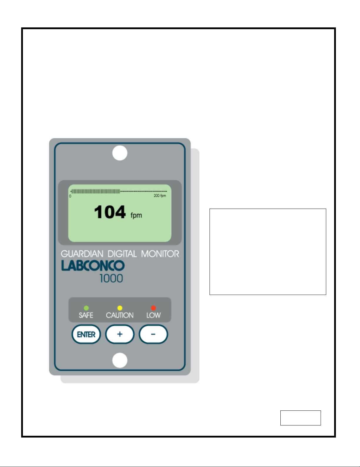
LABCONCO 1000
GUARDIAN DIGITAL MONITOR
Operating and Instruction Manual
Model: Guardian 1000 / 1
• Digital display
• 3 Relay inputs
• 3 Relay outputs
• Com port
Used for alarm indication and
monitoring on Fume Hoods
05/03/04
1
Page 2
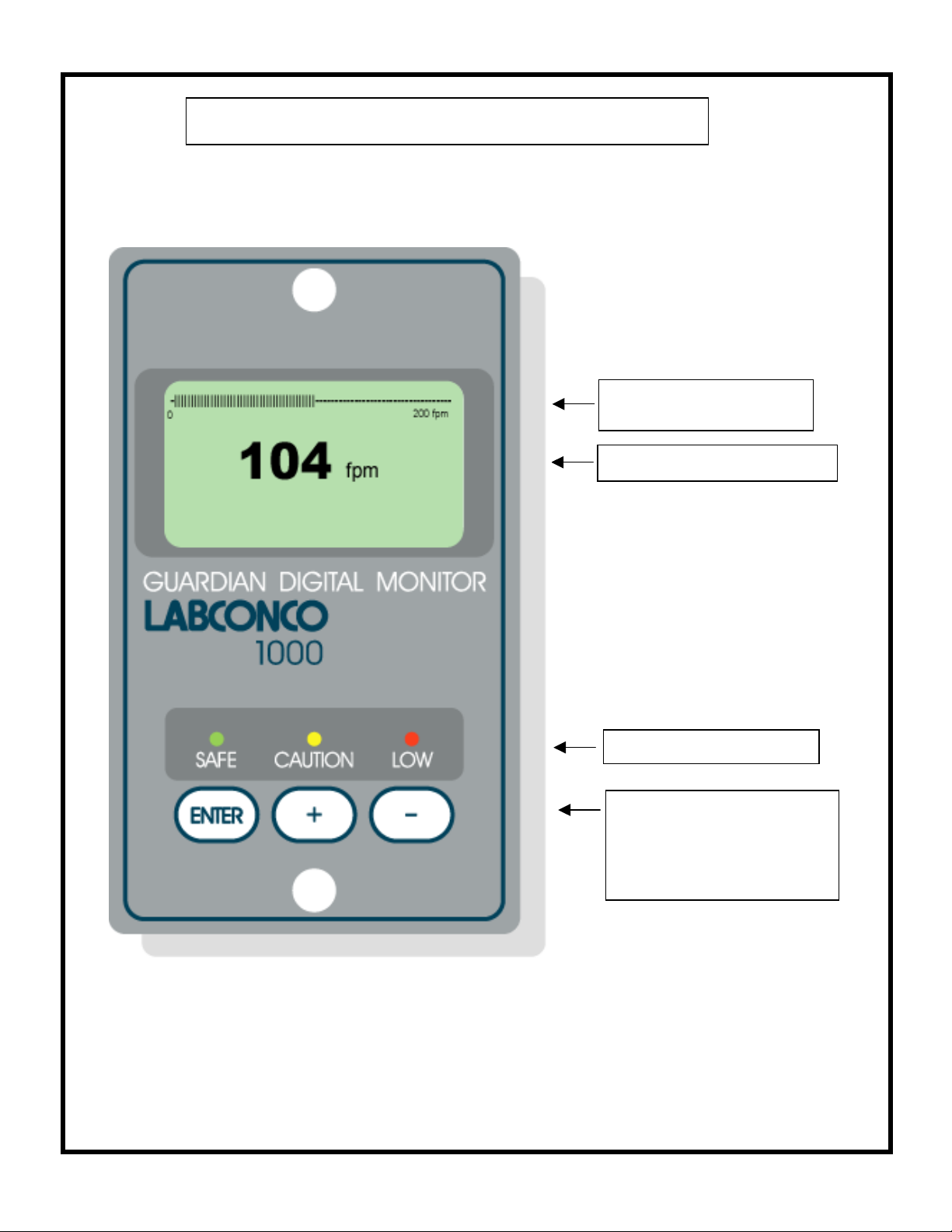
OPERATOR DISPLAY PANEL
Velocity Bar Graph or
Alarm Time Line
Velocity display fpm or m/sec
LED indicators
Function and up/down buttons
for Menu Configuration and
Calibration.
ENTER – also used as
Mute button for audible alarm
Note :- Access to the Calibration and Configuration menus is password protected and is factory
set. To access and or change the password contact the supplier for the Engineers Password and
enter the Passwords in the Main Menu or alternatively use a Laptop connected to the Com port
and the Upload/Download software provided
2
Page 3
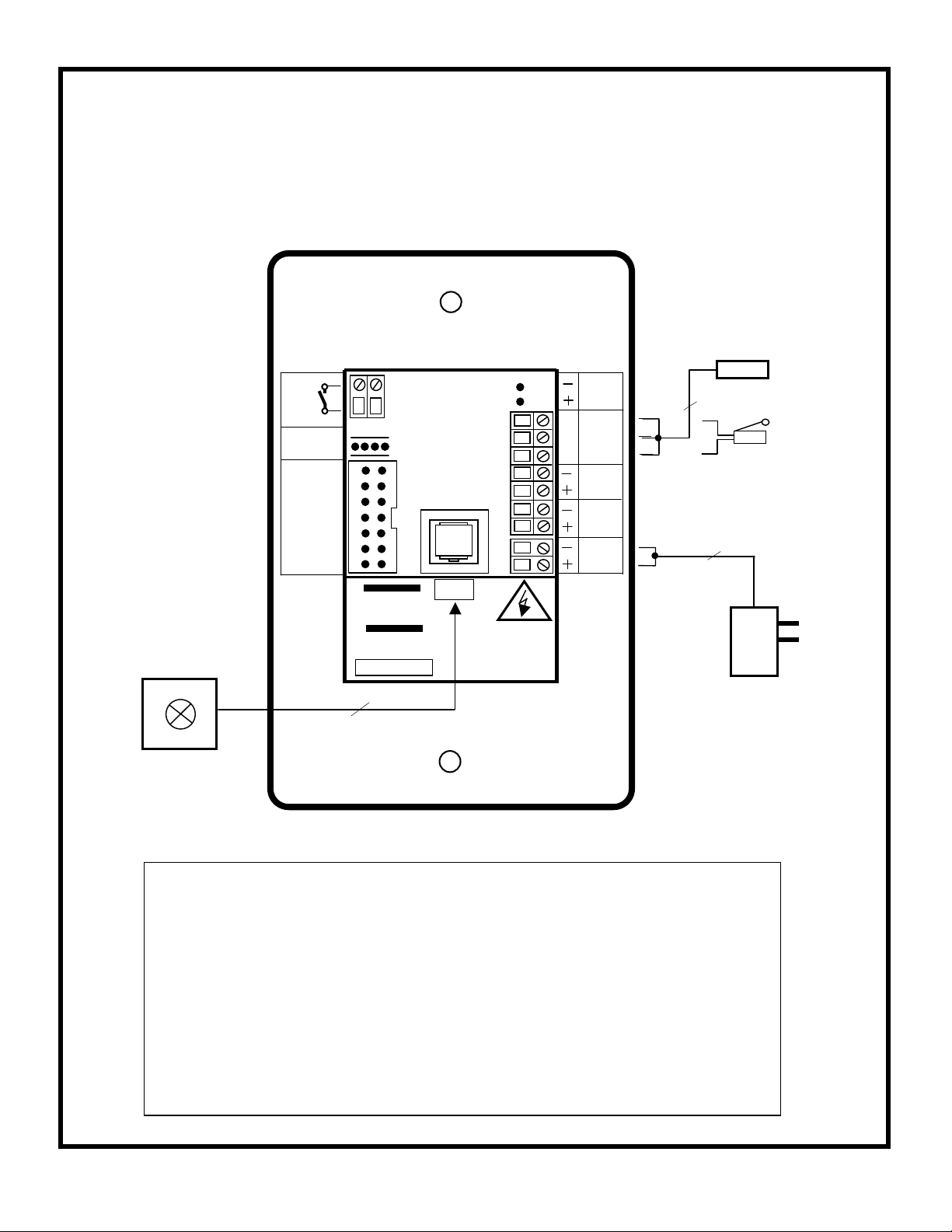
Connection details :-
V
OUTPUT
RELAY
R1
RS 232
Com Port
IDC
14-way
Connector
for remote
Interface Box
( Optional )
SM6 or Inline
Airflow Sensor
Flying lead with RJ11
plug connection for PCB
and SM6 airflow sensor
12V DC
Notes :-
1. The Remote Interface Box is an optional extra. This is supplied
complete with a 2m long ribbon cable with IDC plugs. The box is
designed to allow termination of external cables rated at 220V and
includes the following connection points :-
3 – Input connections – Input 1 , Input 2 , Input 3
3 - Relay outputs - Output relays R1 , R2 , R3
2. Output 1 is an optional extra output giving a 0 –10 V DC signal
proportional to the Fume Hood face velocity over the range
of 0 – 200 fpm
TEL
MADE IN ENGLAND
www.tel-uk.com
AFA 1000 USA
SENSOR
REFER TO
INSTALLATION
INSTRUCTIONS
BEFORE
CONNECTING
Sash High
Proximity switch
( Optional )
0-10
OUTPUT
1
INPUT
Blu
Blk
Brn
Flying lead with plug
connection for PCB
15 V DC
Sash High
Micro - switch
( Optional )
120V
PSU
s/w
-
INPUT 3
+
INPUT 2
INPUT 1
15V DC
POWER
SUPPLY
120V / 15V DC
Plug – in power
adapter for 120V
socket
3
Page 4

1.1 General Description
All systems comprise of the following components :-
1 – SM6 Airflow Sensor,
1 – AFA1000 /1 Alarm unit,
1 – AC power supply
If the Sash Alarm System option is included there will also be a sash micro switch or proximity
switch.
Operator Features
--- the alarm has the following operator features :-
Digital Display
The digital display is a back-lit, full graphic unit with a visual display of approx 56 x 27 mm.
The display operates through the software allowing the generation of figures, wording and Icons.
The display shows the fume cupboard face velocity in m/sec or fpm when enabled or the
alternative with no velocity reading but showing AIR FAIL / AIR SAFE as continuous display.
All of the above are configurable via the alarm key pad.
An ‘ event time line ’ segmented into 20 x 3 minute segments will scroll across the display
( when enabled) .This takes the form of a graphical ‘ blip’ that will progress from the right hand
side to the left hand side – representing events that have occurred during the past hour. On the
standard alarm this will be limited to airflow alarms but other alarms are available.
Using the diagnostics software and an associated computer via the com port on the alarm the
event data can be transferred to a data logger.
The alternative to the event time line is a dynamic ‘ bar graph ’ representing the face velocity
The display shows a Horn icon ( with line through it ) when the audible alarm is in the Muted
condition
Sash High – will be displayed when the Sash alarm is enabled and the sash is raised above
the max safe working opening.
This display will alternate on/off with the velocity reading.
Ext Alarm – will be displayed when the external alarm input is activated ( when enabled )
This display will alternate on/off with the velocity reading
Air Fail - will be displayed if the airflow is less than the Low air alarm point.
This display will alternate on/off with the velocity reading
High Air - will be displayed if the airflow is more than the High air alarm point.
This display will alternate on/off with the velocity reading
Set-back - will be displayed if the night set-back function is activated ( when enabled )
This display will alternate on/off with the velocity reading
Disabled - will be displayed if the alarm disable function is activated ( when enabled )
This display will alternate on/off with the velocity reading
4
Page 5

LED Indicators ---- the alarm unit has three LED indicators : Red -- Alarm
Amber -- Caution
Green -- Safe
Audible Alarm sounder
Mute facility
Enter
--- the alarm has an Enter button -- this is multi-functional as follows : Press Enter momentarily when alarm is sounding will mute the alarm
Press Enter for 5 secs will gain access to Calibration and Configuration
menus ( both menus password protected )
-- the alarm has an audible alarm sounder with local or remote
+ / - -- the alarm has + / - buttons that can be used to scroll through the calibration and
configuration menu or to select options or values
External Connections
Input 1 --- volt free relay input configurable for normally closed or normally open relays
This input can be configured as : Alarm disable
Night set-back
External alarm
Sash High
High / Low
Input 2 --- volt free relay input configurable for normally closed or normally open relays
This input can be configured as : Alarm disable
Night set-back
External alarm
Sash High
High / Low
Input 3 --- volt free relay input configurable for normally closed or normally open relays
This input can be configured as : Alarm disable
Night set-back
External alarm
Sash High
High / Low
-- the alarm unit will have the following connection points :-
5
Page 6

Output 1 --- volt free relay output configurable as normally closed or normally open relays.
Output 2 --- volt free relay output configurable as normally closed or normally open relays.
Output 3 --- volt free relay output configurable as normally closed or normally open relays.
Com Port --- to enable connection to Laptop or PC for full diagnostics , logging or setting
up and for communications to building computer system ( BMS)
Power supply --- low voltage DC power supply
Airflow Sensor --- connection socket for the face velocity airflow sensor.
6
Page 7

1.2 Alarm Configuration / Calibration
The alarm can be configured via a Laptop or PC using a variety of ‘set up ’ programs each
designed for a particular application with a combination of inputs , outputs and push buttons.
This configuration can be changed via the alarm key pad using the menu system if required or
re-configured by re-connection of the laptop or PC.
This allows the fume hood manufacturer to stock standard units and configure the alarms
to suit the application.
The configuration of the various functions and the calibration of the alarm face velocity display is
menu driven. Access to the menu will be via password ( 4 digit number ) and will be two level.
The first level will be for calibration of the unit and the second level will be for ‘engineers’ to set up
the configuration of the alarm.
NOTE:- If you enter the Calibration or Configure Menu by accident :-
press the + & - buttons at the same time to escape back to the Main Menu
The menus and sub–menus are in ‘ plain language ’ and incorporate brief instructions where
appropriate.
See menu operation document
1.3 Start up
When unit is powered up the following sequence of events occur :-
1. The 12V DC power is applied to the airflow sensor and a delay on timer ( 30 sec ) is initiated.
2. The alarm then performs a self test on the display and all indicators etc ( approx 5 sec )
3. The display show a ‘ Welcome note ’ – with the fume cupboard manufacturer company name
( if configured ) for the rest of the initial 30 sec delay time. During this time the airflow sensor
is stabilising
4. During the whole of the 30 sec period all alarms and relay outputs are inhibited.
5. At the end of the 30 sec delay the unit performs one of two options : a. If the alarm calibration has been previously completed – the unit goes to
normal operating mode ( Run )
b. If the unit has not been calibrated the unit displays
‘ Unit requires Set up -- press Enter to access Set up menu ’
The set up menu allows calibration or configuration via the password protection
During the set-up all alarms and output relays are inhibited.
7
Page 8

1.4 Events / actions
Safe airflow
• Meter reading above warning level ( e.g. > 90fpm )
• Green LED on
Warning airflow
• Meter reads between warning level and air fail level ( e.g. > 80fpm and < 90fpm )
• Amber LED on
Low airflow
• Meter reads below alarm level for longer than the warning to low air delay time
• AIR FAIL toggles on / off with display
• Red LED on ( Flashing )
• Audible alarm sounds -- can be muted via Enter pushbutton
• Low air relay operates ( if configured )
Reset : -- when airflow rises 4fpm above Low air level for longer than the low air to
warning air delay time the Low air alarm resets automatically
High airflow
If configured :-
• High Air toggles on / off with display
• Audible alarm sounds – can be muted via Enter pushbutton)
Audible alarm Mute
• When the audible alarm is muted via the Enter button - an Icon ( horn with forward slash) is
shown on the display.
Sash High
• When the input configured as Sash High is activated
• Amber LED on
• Sash High – toggles on / off with velocity display
• Audible alarm sounds
• Audible can be muted via Enter pushbutton -- this silences the alarm and initiates a repeat
timer ( if configured ). After the delay time the alarm re-sounds ( and can be re-muted).
During this time the Amber LED flashes on / off.
• Sash High relay operates ( if configured )
Reset when Sash lowered to safe position and input de-activated.
8
Page 9

High / Low
• When input configured as High/Low is activated
• Display Icon shows High or Low
• High / Low relay operates ( if configured )
This function is designed for two speed fan operation or two position damper operation switched
via a micro switch or proximity switch activated at a given position on the sash.
Night set-back
• When input configured as Night set-back is activated
• Night set-back Icon is displayed
• Red LED on ( Flashing)
• Reduced Low air alarm ( if configured )
• Audible alarm muted
• Mute Icon shown on display
External alarm
• When input configured as External alarm is activated
• Red LED on ( Flashing) – ( if configured )
• External Alarm toggles on /off with display -- ( if configured )
• Audible alarm sounds – can be muted via Enter pushbutton
• External alarm relay operates ( if configured)
Alarm disable
• When input configured as Alarm disable is activated
• Alarm disabled is displayed
• Red LED on ( Flashing)
• Audible alarm muted
• Mute Icon shown on display
9
Page 10

2.1 Quick Start Installation
Follow the instructions below for installing and commissioning the unit. :-
1. Fit the alarm to the Fume Hood using the cut-out details provided with the unit
--- see page 12
2. Fit the airflow sensor to the Fume Hood using the cut out and installation details provided
--- see page 12 ,13 & 14
3. Connect the ‘telephone style’ airflow sensor plug-in cable to the sensor and the back of
the alarm unit --- see typical connection diagram on page 15 & 16
4. Plug in the power adapter to a Mains AC power socket and connect the flying lead to the
alarm unit --- see typical connection diagram on page 15 & 16
Power up the unit and wait at least 30 secs while the sensor temperature stabilises.
5.
6.
If the unit has not been calibrated the unit will display ‘ Requires setup ’ – press ENTER
to continue and in the Main Menu use the +/- buttons on the alarm facia select ‘ SETUP ‘
and then press the ENTER button.
7. In the Setup Menu select ‘CALIBRATION’ and press the ENTER button
8. At this stage you will be requested to enter the PASSWORD. Use the +/- buttons to
select the individual digits in turn and then press ENTER.
If the password is correct the unit will go to the calibration mode. If the password is not
correct you will be requested to try again --- on the third wrong password entry the
calibration menu will lock out for 10 mins
9. When in the calibration mode follow the instructions on the display screen to carry out the
calibration of the unit. See ‘Calibration Notes’ below for hints on successful calibration.
When the calibration is complete the unit will return to the Main Menu.
10. Use the +/- buttons on the alarm facia select ‘ RUN ’ and then press the ENTER button.
The unit will now function and display the measured Fume Hood face velocity
10
Page 11

2.2 Calibration Notes :-
1. When using a standard Fume Hoods with Vertical Sliding sashes open the sash to the
normal max safe working height for the Low Air sample.
2. For the Higher Air sample close the sash to approx 50% of the opening used for the
Lower Air sample. If the Higher air sample value is too close to the Lower Air sample the
alarm will detect this and ask you to repeat with a higher value. To do this close the sash
a little more and repeat the sample. Avoid closing the sash below 100mm.
3. The face velocity readings on the open sash may vary at different points on the
measuring grid by up to 20fpm. This is quite acceptable in terms of the fume cupboard
performance so long as no individual point is below the designated Low Air alarm point
.The figure entered for the calibration point can be taken as the average value of all the
measuring grid readings or could be taken as the individual lowest point on the grid. For
most fume cupboards this low point is on the bottom row in the centre and is a convenient
position to measure and for future reference when checking the alarm during annual
maintenance.
4.
Take time when measuring the face velocities for the calibration procedure to allow for
the velocities across the open sash to stabilise. If the velocities are changing or are
turbulent during the sampling period the alarm will detect this and ask you to repeat the
sample.
5. When using a Fume Hood with Horizontal Sliding sashes open the sashes to the normal
max safe working opening for the Low Air sample.
6. When calibrating or re-calibrating the alarm it is important to ensure that the ‘Vent kit’ is
connected to the SM6 sensor on the fume hood. If the vent kit is not connected the
sensor will not ‘see’ a change in the airflow during the calibration procedure and when
switched to the Run condition the display will show a fixed reading that will not change
when the fume cupboard velocity changes.
If in normal running after successful calibration the vent kit becomes disconnected the air
flow across the sensor will fall and the alarm will go into the AIR FAIL condition.
This only applies during the calibration mode.
11
Page 12

3.0 Dimensions
T
Se
ews provided
Alarm Panel
Dimensions
40.5mm
(1.59 ″)
40.5mm
(1.59 ″)
29mm
(1.14″)
111mm
(4.37 ″)
81mm
(3.19″)
Front
View
Panel Cutout
Dimensions
3.00″ x 2.00″
132mm
(5.2 ″)
76.2mm
(3.00″)
R1
232
IDC
50.8mm
(2.00″)
EL
48mm
(1.89 ″)
Rear
View
lf tapping scr
111mm
(4.37″)
s
1
2
(2.91 ″)
15V
(1.14″)
2 x Fixing Holes
2.5mm dia
for 2 x No. 6
NOT TO SCALE
74mm
29mm
19mm
″)
(0.75
Side
View
9.75mm
(0.38 ″)
12
Page 13

3.0 Dimensions
(
)
(
(
″
)
(
″
)
(
″
)
74mm
(2.91″)
12mm
(0.47″)
17mm
10mm
(0.39″)
SM6 Sensor
Dimensions
( Rear view )
74mm
(2.91″)
12mm
0.47″)
10mm
0.39″
20mm
0.79
12mm Dia.
(0.47″)
SM1 cable
for
25mm
0.98
27mm
1.06
25mm
SM6 Sensor
Panel Cutout
Dimensions
( Front view )
2 x Holes for self tapping fixing
screw.
[ 4mm (0.157″)Fixing Hole
provided on SM6 sensor ]
30mm Dia
(1.18″)
Sensor Hole for
Vent Tube
13
Page 14

4.0 SM6 Airflow Sensor Installation
100mm
100mm
SM6 Airflow Sensor
( See exploded view below )
Normal Sash
wor king h eig ht.
eg. 500mm
25mm
Male
bush
Fume hood
inner skin
25mm
Female adapter
25mm Tube
Fume hood
SM6 Sensor
Open to the
laboratory
outer skin
It is very important to position the SM6 airflow sensor in the correct position to give long term stable reading of the face
velocity. Please read the INSTALLATION NOTES below and if in doubt contact us for further advice.
INSTALLATION NOTES :-
1. The SM6 sensor must be positioned where it can " see " the room pressure of the laboratory.The back connection
spigot of the sensor is designed to accept a 25mm OD tube which should be connected to the inner chamber of
the fume hood. (This tube and fittings is known as the " vent kit " )
The ideal position for the end of the 25mm tube for most fume hoods is 100mm back from the sash glass
and 100mm higher than the normal sash opening height through the inner side wall.
2. If possible mount the sensor on the front of the fume hood and use a short length of tube. Tube lengths of
more than 1metre or smaller diameter will restrict the airflow through the sensor. This will lead to too much
sensitivity being required to calibrate the unit which can lead to some instability of the reading or incorrect
readings at low velocities.
3. For fume hoods with a single skin side wall or a double skin with a small gap between them it may not be
possible to achieve the ideal sensing position using a flexible tube.
With a single skin side wall it is possible to fix the sensor on the outside of the fume cupboard and connect directly
to the inner chamber in the ideal position. This method can only be used for up to two fume cupboards when they
are positioned side by side ( using the two outer walls ).
An alternative method is to mount the sensor on the front of the fume hood and connect using a short flexible
tube to a rigid wall tube attached to the inner side wall. The open end of this rigid wall tube should be positioned in
the ‘ideal position’ ie. 100mm back from the sash and 100mm higher than the normal sash opening.
Fume hoods with a high internal height can present a difficulty because the tube length to reach the ideal
position may be longer than 1 metre. In this case it is better to use a tube no longer than 1 metre which may result
in a sensing position higher than the ideal.
When fitting a sensor to a ’narrow wall’ fume hood for the first time it may be necessary to try various
combinations of rigid and flexible tube to find the best combination and position.
4. The sensor should not be mounted in a position were it is subject to draughts from the laboratory air input or
ventilation system.
NOTE:- ALTERNATIVE IN-LINE SENSOR AVAILABLE Type SM6 FOR FUME HOODS WITH INTERNAL
ACCESS PANEL ON SIDE WALL
14
Page 15

5.0 Typical Wiring Diagram --- (Alarm only)
V
OUTPUT
RELAY
R1
RS 232
Com Port
IDC
14-way
Connector
for remote
Interface Box
( Optional )
SENSOR
TEL
MADE IN ENGLAND
www.tel-uk.com
AFA 1000 USA
REFER TO
INSTALLATION
INSTRUCTIONS
BEFORE
CONNECTING
SM6 or Inline
Airflow Sensor
Flying lead with RJ11
plug connection for PCB
and SM6 airflow sensor
12V DC
Note :
Output 1 is an optional extra output giving a 0 –10 V DC
signal proportional to the Fume Hood face velocity over the
range of 0 – 200 fpm. ( Not included with the standard alarm )
s/w
-
+
0-10
OUTPUT
1
INPUT 3
INPUT 2
INPUT 1
15V DC
POWER
SUPPLY
INPUT
Blu
Blk
Brn
Flying lead with plug
connection for PCB
15 V DC
Sash High
Proximity switch
( Optional )
Sash High
Micro - switch
( Optional )
120V
PSU
120V / 15V DC
Plug – in power
adapter for 120V
socket
15
Page 16

5.1 Typical Wiring Diagram with Optional Relay Interface Unit
V
V
V
Flying lead
Ribbon cable with IDC
plug connection for PCB
and Relay Interface Unit
SM6 or Inline
Airflow Sensor
Optional Relay Interface Unit in ABS enclosure mounted on top of Fume Hood to
allow up to external cable connections to be terminated.
Rated at 220V 5A
0-10
-
s/w
+
0-10
OUTPUT
1
INPUT 3
INPUT 2
INPUT 1
15V DC
POWER
SUPPLY
INPUT
OUTPUT
1
INPUT 1
INPUT 2
INPUT 3
0-10
OUTPUT
2
Blu
Blk
Brn
OUTPUT
RELAY
R1
OUTPUT
RELAY
R2
OUTPUT
RELAY
R3
OUTPUT
RELAY
R1
RS 232
Com Port
IDC
14-way
Connector
for remote
Interface Box
( Optional )
www.tel-uk.com
Flying lead with RJ11
plug connection for PCB
and SM6 airflow sensor
12V DC
TEL
MADE IN ENGLAND
AFA 1000 USA
Relay
Interface
Unit
SENSOR
REFER TO
INSTALLATION
INSTRUCTIONS
BEFORE
CONNECTING
-
s/w
+
Sash High
Proximity switch
( Optional )
Sash High
Micro - switch
( Optional )
Flying lead with plug
connection for PCB
15 V DC
120V
PSU
120V / 15V DC
Plug – in power
adapter for 120V
socket
16
Page 17

6.0 LIMITATION OF WARRANTY AND LIABILITY
Seller warrants that this product, under normal use and service as described in the operator’s manual shall be free from
defects in workmanship and material for a period of twelve (12) months, or the length of time specified in the operator’s
manual, from the date of shipment to the customer. This limited warranty is subject to the following exclusion :-
The foregoing is IN LIEU OF all other warranties and is subject to the conditions and LIMITATIONS stated herein. NO
OTHER EXPRESS OR IMPLIED WARRANTY OF FITNESS FOR PARTICULAR PURPOSE OR MERCHANTABILITY IS
MADE.
THE EXCLUSIVE REMEDY OF THE USER OR PURCHASER, AND THE LIMIT OF LIABILITY OF SELLER FOR ANY
AND ALL LOSSES, INJURIES, OR DAMAGES IN CONNECTION WITH THIS PRODUCT ( INCLUDING CLAIMS BASED
ON CONTRACT NEGLIGENCE, STRICT LIABILITY, OTHER TORT, OR OTHERWISE ) SHALL BE THE RETURN OF
THE PRODUCT TO THE FACTORY OR DESIGNATED LOCATION AND THE REFUND OF THE PURCHASE PRICE,
OR, AT THE OPTION OF THE SELLER, THE REPAIR OR REPLACEMENT OF THE PRODUCT. IN NO EVENT SHALL
SELLER BE LIABLE FOR ANY SPECIAL, INCIDENTAL OR CONSEQUENTIAL DAMAGES.SELLER SHALL NOT BE
RESPONSIBLE FOR INSTALLATION, DISMANTLING, REASSEMBLY OR REINSTALLATION COSTS OR CHARGES.
NO ACTION, REGARDLESS OF FORM, MAY BE BROUGHT AGAINST THE SELLER MORE THAN ONE YEAR AFTER
THE CAUSE OF ACTION HAS ACCRUED.
The purchaser and all users are deemed to have accepted the terms of this LIMITATION OF WARRANTY AND
LIABILITY, which contains the complete and exclusive limited warranty of Seller. This LIMITATION OF WARRANTY AND
LIABILITY may not be amended or modified nor may any of its terms be waived except by a writing signed by an
authorised representative of the Seller.
a. Batteries and certain other components when indicated in specifications are warranted for a period of
90 days from the date of shipment to the customer.
b. With respect to any repair services rendered, Seller warrants that the parts repaired or replaced will
be free from defects in workmanship and material, under normal use, for a period of 90 days from the
date of shipment to the customer
c. Seller does not provide any warranty on finished goods manufactured by others. Only the original
manufacturer’s warranty applies.
d. Unless specifically authorised in a separate writing by Seller, Seller makes no warranty with respect
to, and shall have no liability in connection with, any goods which are incorporated into other
products or equipment by the Buyer. All goods returned under warranty shall be at the Buyer’s risk of
loss, Seller’s factory prepaid, and will be returned at Seller’s risk of loss, Buyer’s factory prepaid.
7.0 Contact us :-
For further information on our range of airflow alarms and controls please
contact us at :-
HSE
Temperature Electronics Ltd
Export sales :-
TEL
Tel
e-mail: xportsales@exportsales.com
web site: www.tel-uk.com
HOLLAND SAFETY EQUIPMENT
726 McKinley Ave.
Libertyville, Illinois 60048
Phone
e-mail: info@hollandsafety.com
web site: www.hollandsafety.com
: + 44 161 257 2541 Fax : + 44 161 228 8817
: 847- 680-9930 Fax : 847-680-9938
17
Page 18

FILE NUMBER
AFA 1000 / 1 -- ALARMS -- ( Velocity )
The AFA1000 alarm has been factory set to the listed parameter settings. To change
any parameter setting press and hold the enter button until the "Main Menu" screen is
displayed, select "Configure" to view the parameters and use the +/- and Enter buttons
FOR FULL INSTALLATION / CALIBRATION / CONFIGURATION DETAILS PLEASE
Menu
ON DISPLAY UNITS
ON LOW AIR ALARM FPM 60
ON LOW AIR CUTOFF
ON CUTOFF SPEED FPM 30
ON
ALARM TO WARNING AIR HYSTERESIS FPM
ON HIGH AIR ALARM
ON HIGH AIR ALARM FPM 295
ON LOWER AIR SAMPLE FLUCTUATIONS % 3
ON HIGHER AIR SAMPLE FLUCTUATIONS % 3
ON LOWER/HIGHER AIR SAMPLE DIFFERENCE FPM 20
ON WARN TO ALARM AIR TIME SECONDS 5
ON ALARM TO WARN AIR TIME SECONDS 1
ON SHOW AIR FLOW
ON SHOW TIME LINE
ON AUDIBLE ALARM
ON SENSOR DIFFERENCE
REFER TO THE DATA BOOKLET PROVIDED.
Configuration Menu: -
Calibration Config
WARNING AIR ALARM FPM 63
to change the settings.
NO = SHOW BAR GRAPH
TYPE
CUSTOMER
Units Default Settings
M/SEC
FPM
OFF
ON
YES
NO
YES ON
NO
YES
ENABLED ENABLED
NOT ENABLED
%
FACTORY DEFAULTS
FPM
ON
3
OFF
OFF
10
Configuration Menu
ON INPUT 1
ACTIVE ON CLOSING CONTACT ACTIVE ON CLOSING CONTACT
ACTIVE ON OPENING CONTACT
ON INPUT 1 - FUNCTION
NOT ACTIVE
NONE
ALARM DISABLE
NIGHT SET-BACK NIGHT SET-BACK
EXTERNAL ALARM
SASH HIGH
HIGH/LOW
2
Page 19

ON INPUT 2
ACTIVE ON CLOSING CONTACT
ON INPUT 2 - FUNCTION
ON INPUT 3
ON INPUT 3 - FUNCTION
ON OUTPUT RELAY 1 ACTIVATION
ON OUTPUT RELAY 2 ACTIVATION
ON OUTPUT RELAY 3 ACTIVATION
ON LOW AIR ALARM - RELAY
ON DISABLE ALARM - RELAY
ON SASH HIGH REPEAT TIMER
ON SASH REPEAT TIME MIN 5
ON SASH HIGH RELAY
ON HIGH / LOW RELAY
ON NIGHT SET-BACK
ON NIGHT SET BACK REDUCED ALARM FPM 49
ON NIGHT SET-BACK RELAY
ACTIVE ON OPENING CONTACT
ACTIVE ON CLOSING CONTACT ACTIVE ON CLOSING CONTACT
ACTIVE ON OPENING CONTACT
CONTACT CLOSES ON ACTIVATION Contact closes on activation
CONTACT OPENS ON ACTIVATION
CONTACT CLOSES ON ACTIVATION Contact closes on activation
CONTACT OPENS ON ACTIVATION
CONTACT CLOSES ON ACTIVATION Contact closes on activation
CONTACT OPENS ON ACTIVATION
NOT ACTIVE Not active
NONE None
ALARM DISABLE
NIGHT SET-BACK
EXTERNAL ALARM
SASH HIGH
HIGH/LOW
NOT ACTIVE
NONE
ALARM DISABLE
NIGHT SET-BACK
EXTERNAL ALARM
SASH HIGH SASH HIGH
HIGH/LOW
NONE
OUTPUT RELAY 1
OUTPUT RELAY 2
OUTPUT RELAY 3
NONE None
OUTPUT RELAY 1
OUTPUT RELAY 2
OUTPUT RELAY 3
ON ON
OFF
NONE None
OUTPUT RELAY 1
OUTPUT RELAY 2
OUTPUT RELAY 3
NONE None
OUTPUT RELAY 1
OUTPUT RELAY 2
OUTPUT RELAY 3
MAINTAIN LOW AIR ALARM Maintain Low Air alarm
REDUCE LOW AIR ALARM
NONE None
OUTPUT RELAY 1
OUTPUT RELAY 2
OUTPUT RELAY 3
OUTPUT RELAY 3
3
Page 20

ON EXTERNAL ALARM - LED
ON EXTERNAL ALARM - DISPLAY ICON
ON EXTERNAL ALARM - RELAY
ON
OFF
ON
OFF
NONE None
OUTPUT RELAY 1
OUTPUT RELAY 2
OUTPUT RELAY 3
OFF
OFF
FACTORY PASSWORDS USER PASSWORD
ALARM SERIAL NUMBER
CONFIG
0000
CALIBRATION
0000
CONFIG
CALIBRATION
4
 Loading...