

Page 1

User’s Manual
CApture
Models
3420000
3420020
3420022
TM
Portable Fuming System
3420024
To receive important product updates,
complete your product registration card
online at register.labconco.com
Labconco Corporation
8811 Prospect Avenue
Kansas City, MO 64132-2696
800-821-5525, 816-333-8811
FAX 816-363-0130
E-MAIL labconco@labconco.com
HOME PAGE www.labconco.com
Page 2

Copyright © 2010 Labconco Corporation. All rights reserved.
The information contained in this manual and the accompanying products are copyrighted and all rights
reserved by Labconco Corporation. Labconco Corporation reserves the right to make periodic design
changes without obligation to notify any person or entity of such change.
Warranty
Labconco provides a warranty on all parts and factory workmanship. The warranty includes areas of
defective material and workmanship, provided such defect results from normal and proper use of the
equipment.
The warranty for all Labconco products will expire one year from date of installation or two years
from date of shipment from Labconco, whichever is sooner, except the following;
• Purifier® Logic® Biological Safety Cabinets carry a three-year warranty from date of
installation or four years from date of shipment from Labconco, whichever is sooner.
• SteamScrubber® & FlaskScrubber® Glassware Washers carry a two-year warranty from date
of installation or three years from date of shipment from Labconco, whichever is sooner.
• Blood Drawing Chairs carry a ten year warranty.
• Carts carry a lifetime warranty.
• Glassware is not warranted from breakage when dropped or mishandled.
This limited warranty covers parts and labor, but not transportation and insurance charges. In the
event of a warranty claim, contact Labconco Corporation or the dealer who sold you the product. If
the cause is determined to be a manufacturing fault, the dealer or Labconco Corporation will repair or
replace all defective parts to restore the unit to operation. Under no circumstances shall Labconco
Corporation be liable for indirect, consequential, or special damages of any kind. This statement may
be altered by a specific published amendment. No individual has authorization to alter the provisions
of this warranty policy or its amendments. Lamps and filters are not covered by this warranty.
Damage due to corrosion or accidental breakage is not covered.
Returned or Damaged Goods
Do not return goods without the prior authorization from Labconco. Unauthorized returns will not be
accepted. If your shipment was damaged in transit, you must file a claim directly with the freight
carrier. Labconco Corporation and its dealers are not responsible for shipping damages.
The United States Interstate Commerce Commission rules require that claims be filed with the delivery
carrier within fifteen (15) days of delivery.
Limitation of Liability
The disposal and/or emission of substances used in connection with this equipment may be governed by
various federal, state, or local regulations. All users of this equipment are required to become familiar
with any regulations that apply in the user’s area concerning the dumping of waste materials in or upon
water, land, or air and to comply with such regulations. Labconco Corporation is held harmless with
respect to user’s compliance with such regulations.
Contacting Labconco Corporation
If you have questions that are not addressed in this manual, or if you need technical assistance, contact
Labconco’s Customer Service Department or Labconco’s Product Service Department at 1-800-8215525 or 1-816-333-8811, between the hours of 7:00 a.m. and 6:00 p.m., Central Standard Time.
Part #3421500, Rev. -
ECO F844
Page 3

T
AABBLLEE
T
CHAPTER 1: INTRODUCTION 1
CHAPTER 2: PREREQUISITES 2
Supplies Required 2
Exhaust Requirements 3
Electrical Requirements 3
CHAPTER 3: THEORY OF OPERATION AND SAFETY
CA Polymerization 4-5
Generation of CA Fumes Through Controlled Heating 5
Clear Chamber 5
Two Stage Filter System 5
Blower 6
Safety Precautions 6-7
CHAPTER 4: USING THE SYSTEM 8
Unpacking the System 8-9
Transporting the System 9
Component Identification 10
Hints for Handling CA 11
Preparing the System for Operation 12-16
Set Up 12-13
Heater Adjustment 14
Fuming Procedure 15-16
CHAPTER 5: MAINTAINING THE SYSTEM 17
Routine Maintenance Schedule 17
Service Operations 18-19
Filter Replacement 18-19
Resetting the Circuit Breaker 19
CHAPTER 6: TROUBLESHOOTING 20
APPENDIX A: COMPONENTS 21
O
O
PRECAUTIONS 4
FF
C
C
OONNTTEENNTTSS
Page 4

APPENDIX B: DIMENSIONS 22
APPENDIX C: SPECIFICATIONS 23
APPENDIX D: ACCESSORIES 24
DECLARATION OF CONFORMITY 25
Page 5

CChhaapptteerr 11::
IInnttrroodduuccttiioonn
Congratulations on the purchase of a Labconco CApture Portable Fuming
System. The CApture is unique, offering a self-contained, portable system for
developing latent fingerprints using the cyanoacrylate (CA) fuming method.
CApture has a solid state heater control, exhaust fan, and an internal two
stage filter to remove CA fumes at the end of the development process.
The Portable Fuming System offers many unique features to enhance
performance and flexibility. To take full advantage of them, please acquaint
yourself with this manual and keep it handy for future reference. Because of
its uniqueness, even if you are familiar using the CA fuming method, please
review both Chapter 3: Theory of Operation and Safety Precautions and
Chapter 4: Using the System; which describe the CApture’s features so that
you can use it efficiently.
This manual and other technical information is available in PDF format
at our website: www.labconco.com.
Product Service 1-800-522-7658
1
Page 6

CChhaapptteerr 22::
PPrreerreeqquuiissiitteess
Carefully read this chapter to learn:
• Supplies required.
• Electrical power requirements.
• Exhaust requirements.
Supplies Required
Before you use the Fuming System, you need get the following items:
• 1 bottle of CA glue (the capacity of the filter is approximately
2 ounces (57gm))
Note: For best results, do not use CA with thickening or gap filling
formulations.
• A supply of aluminum heating pans, in addition to the 10 shipped
with the unit. A bag of 250 pans is available as Labconco part number
34252002.
• A supply of Rain-X* or Rain Block**
to treat the clear chamber
before use.
*Rain-X is a registered trademark of Sopus Products.
**Rain Block is a trade mark of Value Smart Products, Inc.
2
Product Service 1-800-522-7658
Page 7
Chapter 2: Prerequisites
Exhaust Requirements
If you intend to connect the system to the optional Exhaust Connection Kit,
first examine the location to ensure that the exhaust duct can be directed
either out of the immediate area (through a partially opened window), or into
a chemical fume hood. For further information about the CApture’s exhaust
system requirements, please refer to Appendix D: Accessories.
Note: For best results, do not add any additional exhaust duct to that already
supplied in the exhaust connection kit. Additional lengths of duct will reduce
the exhaust flow out of the chamber, possibly resulting in incomplete venting
of the CA fumes.
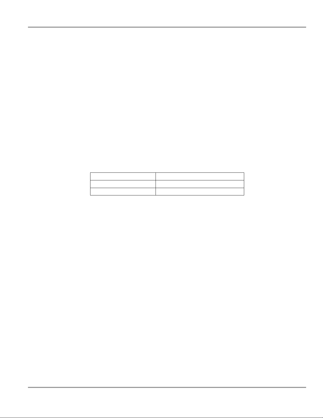
Electrical Requirements
The system models have the following electrical requirements:
Model # Requirements
3420000 115 VAC, 60 Hz, 1 Amp
34200-20, -22, -24 230 VAC, 50/60 Hz, 0.5 Amp
Table 2-1
Note: An outlet with a circuit breaker rated at 10 amps for 115 volt
models (5 amps for 230 volt models) should be located as close as possible
to the system. Power cords supplied with the print system are 3 meters
(10 feet) long.
Note: The system can be operated on an inverter, converting 12 Volts DC
to the appropriate AC voltage. The inverter should have an output
rating of at least 100 Watts, and protected against current overload for
proper operation.
Product Service 1-800-522-7658
3
Page 8

CChhaapptteerr 33::
TThheeoorryy ooff OOppeerraattiioonn aanndd SSaaffeettyy
PPrreeccaauuttiioonnss
The CApture operates using the following principles:
• CA polymerization.
• Generation of CA fumes through controlled heating.
• Removal of CA droplets and fumes by a two stage filter.
The major components in the system are:
• The clear chamber
• The controller and heater.
• The two stage filter.
• The blower to force air through the system.
CA polymerization
Cyanoacrylate is the generic name for fast-acting adhesives such as methyl 2cyanoacrylate or ethyl-2-cyanoacrylate. CA adhesives are sometimes known
as "instant glues." CA is an acrylic resin which rapidly polymerizes in the
presence of water (specifically hydroxide ions), forming long, strong chains,
joining the bonded surfaces together. CA is a tenacious adhesive, particularly
when used to bond non-porous materials or those that contain minute traces
of water. It is also very good at bonding body tissue, and this can be a
bothersome (or even dangerous) side effect during everyday use.
Cyanoacrylate is used as a forensic tool to capture latent fingerprints on nonporous surfaces such as glass, plastic, etc. The cyanoacrylate fuming method
(often called the super glue method) heats the CA to produce fumes which
react with amino acids, fatty acids, and proteins in the latent fingerprint and
the moisture in the air to produce a visible, sticky white polymer
4
Product Service 1-800-522-7658
Page 9

Chapter 3: Theory of Operation & Safety Precautions
(polycyanoacrylate) on the fingerprint ridges. The ridges can then be
recorded. The developed fingerprints are, on most surfaces (except on white
plastic or similar), visible to the naked eye. The reaction must be monitored
to ensure that it is not allowed to continue for too long. If it runs unchecked,
the latent fingerprints can overdevelop and the chemical images of the ridges
will slowly grow wider until they overlap, obscuring vital detail.
Generation of CA fumes through controlled
heating
CA adhesives have a boiling point of approximately 120°F (50°C). With
increasing heat, cyanoacrylate decomposition products begin to appear at
temperatures above 250°F (121°C), and when the temperature exceeds 400°F
(204°C), hydrogen cyanide can be produced. It is therefore critical to
maintain a consistent, controlled heat throughout the development process.
The CApture Print System uses a heater, controlled by a digital controller.
The user-programmed controller maintains the set temperature between the
minimum of 120°F (50°C) and maximum of 350°F (177°C). A redundant
safety switch limits the heater temperature to a maximum of 350°F (177°C),
in the event of a controller malfunction.
Clear Chamber
The clear chamber is made out of durable, shatter-resistant polycarbonate. It
protects the heater/filter module when the unit is being transported, and
allows an unobstructed view of the evidence during the fuming process.
While the clear chamber is resistant to many chemicals, it is not resistant to
CA fumes, and it MUST be treated with either Rain-X® or Rain BlockTM
glass water repellent. Labconco has tested these two treatments, and found
they protect the clear chamber from CA fumes for up to 20 uses, if properly
applied, and the treatment is not disturbed. Always follow the treatment
manufacturer’s instructions when applying the treatment. Labconco has not
tested any other brands of glass treatment chemicals, and cannot recommend
their usage.
Two Stage Filter System
CA droplets and fumes are removed from the air in the clear chamber by a
two stage filtration system. The first stage of the filter cartridge is a polyester
loft particulate filter, having a Minimum Efficiency Reporting Value
(MERV) of 11, meaning it removes 65-79% of particles 1.0-3.0 microns in
size, and more than 85% of particles 3.0-10 microns in size. The second stage
of the filter is specially prepared granular activated carbon (GAC) that
adsorbs any gaseous CA as the air flows through the carbon bed. See
Appendix A for replacement part numbers. Using the recommended amount
of CA for proper development, the filter should last for a minimum of 100
fuming cycles (about 2 oz, or 57ml) before replacement.
Product Service 1-800-522-7658
5
Page 10

Chapter 3: Theory of Operation & Safety Precautions
Blower
The blower assembly pulls air out of the clear chamber, through the filter,
and then exhausts it out of the system.
Safety Precautions
Always wear appropriate personnel protective equipment (PPE), such as
protective eyewear and gloves when handling CA, its byproducts or residue.
CA fumes irritate sensitive membranes in the eyes, nose and throat. They are
immediately polymerized by the moisture in the membranes and become
inert. These risks can be minimized by using CA in well ventilated areas.
About 5% of the population can become sensitized to CA fumes after
repeated exposure, resulting in flu-like symptoms. It may also act as a skin
irritant and may cause an allergic skin reaction. On rare occasions inhalation
may trigger asthma.
Applying cyanoacrylate to materials made of cotton or wool (such as cotton
swabs, cotton balls, and certain yarns or fabrics) results in a powerful, rapid
exothermic reaction. The heat released may cause minor burns, and if enough
cyanoacrylate is used, the reaction is capable of igniting the cotton product,
as well as releasing irritating vapor in the form of white smoke. Material
Safety Data Sheets for cyanoacrylate instruct users not to wear cotton or wool
clothing, especially cotton gloves, when applying or handling cyanoacrylates.
Recommended solvents for removing polycyanoacrylate residue from the
metallic surfaces of the Fuming System include:
• Acetone - Commonly found in nail polish remover.
• Nitromethane
• Dimethyl sulfoxide
• Gamma-butyrolactone – Effective and has low toxicity.
NEVER use these chemicals to remove CA or its residue from the eyes or
sensitive mucous membranes. Seek medical attention if needed. NEVER use
these chemicals to remove CA or its residue from the clear chamber, as they
will damage the plastic.
Ensure that the system is connected to electrical service in accordance with
local and national electrical codes. Failure to do so may create a fire or
electrical hazard. Do not remove or service any electrical components
without first disconnecting the unit from electrical service.
The system is only designed to heat cyanoacrylate. NEVER use this unit to
heat any other chemicals.
6
Product Service 1-800-522-7658
Page 11

Chapter 3: Theory of Operation & Safety Precautions
NEVER put CA or water directly on the heater surface. ALWAYS put water
or CA into heating pans, and then place these on the heater.
NEVER exceed 8 drops of CA per development cycle.
NEVER operate the system without the clear chamber attached to the
stainless steel face plate. The Portable Fuming System was not designed to
generate CA fumes for large areas or volumes.
NEVER attempt to override the temperature controller or the over
temperature switch; Serious damage to the heating element and/or other parts
of the system may result.
NEVER attempt to develop evidence containing flammable gases or solvents.
Do not operate the system without the appropriate filter in place. If an odor is
detected coming out of the granular activated carbon, it needs to be replaced.
The system weighs approximately 22 lbs. (10 kg). Always follow safe-lifting
guidelines when transporting the unit.
When cleaning the system:
• Always wear appropriate personnel protective equipment.
• NEVER use solvents to clean the clear chamber. Use mild soap or
detergent and warm water to clean the chamber.
• NEVER spray cleaner or any liquid into the fan exhaust located on
the top of the system; this may damage the blower.
• Ensure adequate room ventilation.
• DO NOT allow bleach or disinfectants with high concentrations of
free chlorine to contact the stainless steel components of the system
for a long period of time. Free chlorine will corrode stainless steel
after extended contact.
Product Service 1-800-522-7658
7
Page 12

CChhaapptteerr 44::
UUssiinngg tthhee SSyysstteem
This chapter covers how to:
• Unpack and transport the system.
• Hints for handling CA.
• Connecting the electrical supply source.
Except a box knife to open the carton, no tools are required for preparation of
the system.
Note: The system weighs approximately 22 lbs. (10 kg). Always follow
safe-lifting guidelines when transporting the unit.
m
Unpacking the System
Carefully open the carton and inspect the system for damage that may have
occurred in transit. If the system is damaged, notify the delivery carrier
immediately and retain the entire shipment intact for inspection by the
carrier.
Note: United States Interstate Commerce Commission rules require that
claims be filed with the delivery carrier within fifteen (15) days of delivery.
Do not return goods without the prior authorization of Labconco.
Unauthorized returns will not be accepted.
If the unit was damaged in transit, you must file a claim directly with the
freight carrier. Labconco Corporation and its dealers are not responsible for
shipping damages.
Do not discard the carton or packing material for the system until all of the
components have been checked, installed and tested.
8
Product Service 1-800-522-7658
Page 13

Chapter 4: Using the System
Note: The following are located in the carton:
• User’s Manual
• Product Registration Card
• Filter Service Reminder Card
Located in the clear chamber:
• Foam Storage Insert (DO NOT DISCARD), containing:
o Power Cord
o 10 Heating Pans
o 1 Hook
o 1 Shelf
o 1 Pair of Pliers
If you did not receive one or more of the components listed for the
system contact Labconco Corporation immediately for further
instructions.
The system is shipped in the transport mode, as shown in Figure 4-1
Figure 4-1
Transporting the System
When transporting the system, the unit should be in transport mode, with the
heater/filter module nested in the clear chamber and the transport lid locked
on top.
Note: NEVER transport the system in the operating mode (Figure 4-2a). The
heater/filter module can be damaged by rough handling when not protected
by the clear chamber.
Product Service 1-800-522-7658
9
Page 14

Chapter 4: Using the System
Component Identification
Figure 4-2a
Clear Chamber
Digital Temperature Controller
Maintenance Panel Thumbscrew
Control Switch (Heat-Off-Vent)
Circuit Breaker/Main Power Switch
Power Cord Connection
Heater Receptacles (2)
Leveling Foot Pin
Leveling Foot
Figure 4-2b
Blower Exhaust
Stainless Steel Face Plate
Manifold
Position for Control Slide
Heater Door
CA Fume Outlet
Filter Cartridge Intake and Seal
Shelf
10
Product Service 1-800-522-7658
Page 15

Hints for Handling CA
Chapter 4: Using the System
NEVER use the system without first protecting the inside surfaces of the
TM
clear chamber with Rain-X® or Rain Block
glass water repellent.
Labconco has tested these two treatments, and found they protect the clear
chamber from CA fumes for up to 20 uses, if the treatment is not disturbed.
Always follow the treatment manufacturer’s instructions when applying the
treatment. Labconco has not tested any other brands of glass treatment
chemicals, and cannot recommend their usage.
CA will react and polymerize on any surface or material that is wet or damp.
NEVER use the system on wet or damp evidence.
If the relative humidity of the operating environment is less than 30%, and
you wish to increase the humidity in the clear chamber before developing
fingerprints, place NO MORE THAN 1-2 drops of water in a heating pan,
and place it on the heater. Using more than 1-2 drops of water will result in
saturation of the air and condensation inside the clear chamber. The CA
fumes will react with condensation, reducing the clarity of the chamber.
NEVER use the system when there is condensation on the inside of the clear
chamber or on evidence.
If you are trying to reuse CA heating pans, discard them after the second use.
If reused more than a single time, buildup of residue on the bottom of the pan
will affect the transfer of heat to the glue.
Don’t use any heating pan with a dented or warped bottom; it will not heat
the CA as efficiently.
Because the presence of moisture causes the glue to set, exposure to moisture
in the air can cause a tube or bottle of glue to become unusable over time. To
prevent an opened container of glue from setting during long term storage,
store it in a freezer, or in an airtight jar or bottle with a package of silica gel.
Product Service 1-800-522-7658
11
Page 16

Chapter 4: Using the System
Using the System
Set Up
After the Portable Fuming System has been removed from its carton and
positioned in a suitable location, you must:
1. Release the two clamps
securing the transport cover to
the clear chamber, as shown in
Figure 4-3. Set the transport
cover aside. Lift the heater/filter
module out of the chamber.
Remove the accessories and the
foam storage insert from the
bottom of the clear chamber.
Figure 4-3
2. Put the leveling foot in the down
position by pulling the pin out and
sliding the foot down until the pin sets,
as shown in Figure 4-4.
1. Before using the system, protect the
inside surface of the clear chamber with
Rain-X® or Rain Block
repellent. Labconco has tested these
two treatments, and found they protect
the clear chamber from CA fumes for
up to 20 uses, if the treatment is not
disturbed. Always follow the treatment
manufacturer’s instructions when
applying the treatment.
TM
glass water
Figure 4-4
12
Product Service 1-800-522-7658
Page 17

Chapter 4: Using the System
Figure 4-5
2. Select the hooks or shelves
needed to hang or support the
evidence to be developed. Engage
the hooks and/or shelves into the
appropriate holes on the stainless
steel face plate, as shown in
figure 4-5.
3. Place the evidence so that fumes
can contact as much of its surface
as possible. If desired, place a
control fingerprint on a glass
slide, and set the slide into one of
the slide slots in the face plate.
4. Seal the clear chamber to the stainless face plate, using the clamps on
either side of the chamber. The unit is now in operating mode, as
shown in Figure 4-2a and 4-2b.
5. Plug the unit in, and make sure the main power switch is in the “ON”
position.
Product Service 1-800-522-7658
13
Page 18

Chapter 4: Using the System
Heater Adjustment
1. Push the control switch to the “Heat” position. The temperature of the
heater will be displayed on the controller, as shown in Figure 4-6.
When the heater is on, the “out” indicator will be lit.
2. To check or change the temperature setting:
a. Press SET. “SP” will appear on the display.
b. Press SET again. The current temperature setting is displayed.
c. The setting can be changed by pressing the UP or DOWN
buttons. The heater temperature must range between 120o and
350oF (50o-177oC).
d. Press the SET button to enter the new setting.
Figure 4-6
Out Indicator Light
Heater Temperature
“UP” Button
“DOWN” Button
“SET” Button
e. Press SET and DOWN at the same time to exit the
programming mode.
3. Within 3-5 minutes, the temperature of the heater will stabilize at the
setpoint (+/- 15 degrees).
14
Product Service 1-800-522-7658
Page 19

Chapter 4: Using the System
Fuming Procedure
1. Ensure that the inside of the chamber and the evidence being fumed is
dry, and has no condensation on it.
2. If the relative humidity of the operating environment is less than 30%,
you may wish to increase the humidity in the clear chamber. Place
NO MORE THAN 1-2 drops of water in a heating pan, open the
heater door, and place it in one of the heater receptacles. Close the
heater door, as shown in Figure 4-7.
Figure 4-7
Heater receptacles
Place pan here to cool during
venting
Heater door latch (slide to open)
3. Open the heater door. Place approximately 4-6 drops of CA glue in a
heating pan, and place it in one of the heater receptacles, and
immediately close the door.
Note: Do not use more than 8 drops of CA per development cycle.
4. Carefully observe the control evidence for the development of prints.
Print development times may vary, depending on the amount of CA
used, relative humidity, heater temperature, etc. Typical development
o
times run 3-5 minutes with 4 drops of CA, at 350
F (177oC).
5. When the prints are developed as desired, switch the control switch
from “Heat” to “Vent.” Open the heater door, and place the heating
pan containing the remaining CA residue on the space between the
heater receptacles. This will allow the CA heating pan to cool, and
stop generating fumes.
6. Let the chamber vent for at least 3-5 minutes before opening the
chamber and retrieving the evidence.
7. If more evidence needs to be developed, turn the control switch to
“Heat” and go back to step #1 and repeat.
8. If no more evidence needs to be developed, push the control switch to
the center “OFF” position.
9. Remove any heating pans from the heater receptacles.
Product Service 1-800-522-7658
15
Page 20

Chapter 4: Using the System
10. Remove any evidence hooks or shelves from the stainless steel face
plate.
11. Wipe up any residue from the stainless steel face plate and the clear
chamber.
12. Unplug the unit. Stow the foam storage insert and the accessories in
the bottom of the clear chamber.
13. Raise the leveling foot to the up position by pulling the pin out, and
sliding the foot up until the pin sets, as shown in Figure 4-4.
14. Place the heater/filter module into the clear chamber, ensuring that is
fits into the chamber completely.
15. Place the transport lid back on top of the stainless steel face plate, and
reengage the two clamps securing the transport cover to the clear
chamber. The unit is now ready for transport or storage.
16
Product Service 1-800-522-7658
Page 21

CChhaapptteerr 55::
MMaaiinnttaaiinniinngg tthhee SSyysstteem
The common service operations necessary to maintain the CApture Portable
Fuming System’s peak performance are listed below.
m
Routine Maintenance Schedule
Weekly
• Using an appropriate soap or detergent solution, or LabSolutions
Glass & Surface Wipes, Labconco part # 1570000; clean the stainless
steel face plate.
• If the inside surface of the clear chamber is cleaned, reapply either
Rain-X® or Rain Block treatmentTM.
Monthly (or more often as required)
• Using a damp cloth, or LabSolutions Glass & Surface Wipes,
Labconco part # 1570000; clean the exterior surfaces of the system, to
remove any accumulated dust.
• All weekly activities.
After every 20 development cycles
• Carefully clean the clear chamber with mild detergent or glass
cleaner. When thoroughly clean and dry, treat the inside of the
chamber with Rain-X® or Rain Block treatment
After every 100 development cycles
• Replace the filter cartridge.
Product Service 1-800-522-7658
TM
.
17
Page 22

Chapter 5: Maintaining the System
Service Operations
Filter Replacement:
1. Unplug the system. Separate the heater/filter module from the clear
chamber. Place the module with the stainless steel face plate down on
a stable, level surface, as shown in Figure 5-1.
Figure 5-1
2. Loosen the maintenance
panel thumbscrew. It is
a captive screw, and
will be retained by the
panel.
3. Remove the panel from the module, and locate the filter cartridge, as
shown in Figure 5-2.
Flexible Connector
Filter Cartridge
Figure 5-2
18
Product Service 1-800-522-7658
Page 23

Chapter 5: Maintaining the System
4. Grasp the filter cartridge and pull the bottom of the cartridge until the
filter cartridge inlet pulls out of the filter cartridge seal. Keep pulling
the bottom of the cartridge out until it clears the back edge of the
heater/filter module, then pull it out of the flexible connector.
5. Discard the used cartridge, and install a replacement, by reversing the
removal steps.
6. Ensure that the filter cartridge seal has not been deformed during
installation of the new filter cartridge.
Resetting the Circuit Breaker:
To reset the circuit breaker located on the rear of steel system module, press
the switch to the “on” (I) position.
Product Service 1-800-522-7658
19
Page 24

CChhaapptteerr 66::
TTrroouubblleesshhoooottiinngg
Refer to the following table if the system fails to operate properly. If the
suggested corrective actions do not solve the problem, contact Labconco for
additional assistance.
PROBLEM CAUSE CORRECTIVE ACTION
Blower and controller
won’t turn on
Circuit breaker tripped Reset circuit breaker.
Prints are not
developing properly
Little or no fumes are
being produced
Bottom of heater pan is
Heater temperature not
changing on controller
(“out” indicator is on)
Heater temperature not
changing on controller
(out indicator is off)
Fan does not run
Controller displays “Er”
or “oo” or “-”
Unit not plugged into
outlet
Insufficient humidity in
the clear chamber
Heater temperature is
too low.
dented/bent
Heater /Over
temperature switch
failure
Controller is defective Contact Labconco Product Service
Fan or 12 volt power
supply failure
Controller error Contact Labconco Product Service
Plug the cabinet into appropriate electrical
service.
Place 1-2 drops of water in a heating pan,
and place on the heater.
Increase heater temperature
Discard damaged pan, and use one with flat
bottom.
Contact Labconco Product Service
Department.
Department.
Contact Labconco Product Service
Department.
Department.
20
Product Service 1-800-522-7658
Page 25

AAppppeennddiixx AA::
CCoom
CApture Portable Fuming System Parts
Item Quantity Part No. Description
1 1 3421901 Clear chamber
2 1 3425202 Heating pans, package of 250 (not shown)
3 1 3424500 Flexible Connector
4 1 3421801 Filter Cartridge
5 1 3422203 Shelf
6 1 3422202 Hook (not shown)
7 1 3425500 Foam Storage Insert (not shown)
mppoonneennttss
1
3
4
5
Product Service 1-800-522-7658
21
Page 26

AAppppeennddiixx BB::
meennssiioonnss
DDiim
B-1
Clear Chamber Interior Dimensions:
16”(406mm)H x 8”(203mm)W x 8” (203mm)D
22
Product Service 1-800-522-7658
Page 27

AAppppeennddiixx CC::
SSppeecciiffiiccaattiioonnss
Electrical Data
Model # Requirements Energy Use
3420000 115 VAC, 60 Hz, 1 Amp 75 Watts
34200-20, -22, -24 230 VAC, 50/60 Hz, 0.5 Amp 75 Watts
Environmental Conditions
• Indoor use only.
• Maximum altitude: 6562 feet (2000 meters).
• Ambient temperature range: 41° to 104°F (5° to 40°C).
• Maximum relative humidity: 80% for temperatures up to 88°F
(31°C), decreasing linearly to 50% relative humidity at 104°F (40°C).
• Main supply voltage fluctuations not to exceed ±10% of the nominal
voltage.
• Transient overvoltages according to Installation Categories II
(Overvoltage Categories per IEC 1010). Temporary voltage spikes on
the AC input line that may be as high as 1500V for 115V models and
2500V for 230V models are allowed.
• Used in an environment of Pollution degrees 2 (i.e., where normally
only non-conductive atmospheres are present). Occasionally,
however, a temporary conductivity caused by condensation must be
expected, in accordance with IEC 664.
Product Service 1-800-522-7658
23
Page 28

AAppppeennddiixx DD::
AAcccceessssoorriieess
Clear Chamber (# 3421901)
Replacement clear chamber, with latches installed. 2 lb. (0.9kg).
Heating Pans (#3425202)
Package of 250 aluminum disposable heating pans. 1 lb. (0.5kg).
Filter Cartridge (#3421801)
Replacement particulate/ granular activated carbon filter cartridge. Lasts for
100 development cycles. 5 lbs. (2.3kg).
Exhaust Connection Kit (#3425400)
Allows the system to exhaust to a remote location, or a nearby chemical fume
hood. Includes 10’ (1.2m) long (extended full length), 4” (100 mm) diameter
collapsible duct. 1 lb. (0.5kg).
Replacement Hook (#3422202)
Allows for evidence to be hung in the clear chamber during development. 1
lb. (0.5kg).
Replacement Shelf (#3422203)
Allows for small evidence to be supported in the clear chamber during
development. 1 lb. (0.5kg).
Perforated Shelf Cover (#3426101)
Stainless Steel perforated cover fits over Shelf #3426103. The Cover allows
for small evidence to sit on the shelf during development. 1 lb. (0.5kg).
24
Product Service 1-800-522-7658
Page 29

Product Service 1-800-522-7658
25
 Loading...