

Page 1

LABCONCO CORPORATION 8811 Prospect Ave, Kansas City, MO 64132
(816) 333-8811, Fax (816) 363-0130, (800) 821-5525
Anti-Static Ionizer Fan No. 5234400 or 5234401
Operation
The ionizer fan is a dual steady state DC circulator that moves ionized air inside the glove box to
reduce static charge. The ionizer fan, mounting bracket, transformer, and conduit are included in
the accessory kit and can be easily attached to the inside of the glove box main chamber ceiling,
near the fluorescent light. For a more detailed review, simple maintenance, and adjustment
please read the section on “Ionizer Fan Performance” at the back of this instruction sheet. To
properly install the ionizer fan, follow the steps next under “Installation Procedure.”
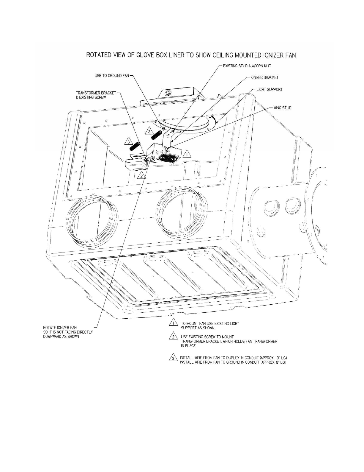
Installation Procedure
1. The Precise Glove Box comes prepared to accept the Ionizer Fan, it easily mounts to the
light support inside the main chamber. The Ionizer Fan is included with the XPert Weigh
Box.
2. Use the existing stud located in the pictorial and remove the acorn nut. Save the acorn nut
for the next step.
3. Take the bracket supplied and mount it to the stud with the acorn nut. Tighten the acorn
nut.
4. Mount the ionizer fan to the bracket with the wing stud and rotate the ionizer fan so it is
not facing directly downward onto the work surface.
5. a.) For 100V or 115V operation, connect the 12 volt DC Power Supply and conduit to
either the switched outlet (right side) or the “always on” (left side) outlet mounted on the
glove box interior ceiling. A bracket is supplied to support the power supply; it is
installed using the middle screw of the electrical outlet plate.
b.) For 230V operation, connect the 12 volt DC Power Supply to the European power strip
and then connect the 230V US plug from the European power strip to either outlet on the
glove box interior ceiling as described above. Tie wraps are supplied to secure the 12 volt
DC Power Supply cord to the cord from the European power strip.
6. Connect the grounding strap to the other acorn nut or the mounting bracket as shown in
the pictorials.
7. Test the ionizer fan for power on; you should hear it running.
8. Adjust the fan speed and the balance adjustment per the “Ionizer Fan Performance” listed
after the pictorial. The ionizer fan is dependent on humidity and static electricity
conditions inside the glove box. For optimum performance, we recommend that you use a
surface DC voltmeter to adjust the balance of the ionizer fan. Without any adjustment, the
ionizer fan will reduce static electricity quite effectively, but not optimally. For example,
with the ionizer fan off, the static voltages may be 100 to 800 volts, but with it on, the
static voltages will be reduced to +/- 0 to 250 volts. With the ionizer fan neutralization
optimally adjusted, the static voltages will be reduced further to +/- 0 to 100 volts.
Labconco Instruction Sheet 5234404, Rev. A, ECO E275 1 of 6
Page 2
Labconco Instruction Sheet 5234404, Rev. A, ECO E275 2 of 6
Page 3

Labconco Instruction Sheet 5234404, Rev. A, ECO E275 3 of 6
Page 4

Ionizer Fan Performance
The static electricity tests were performed by monitoring the level of static electricity voltages
found on the work surface and interior surfaces within the glove box. Static electricity levels were
measured with an AlphaLab™ Surface DC Voltmeter (http://scientificmeter.com/surface_dc.htm).
A DESCO™ Emit Mini Zero Volt Ionizer (http://www.descoemit.com/ViewProduct.aspx?pid=
50661&h=1323
balancing bench top ionizer. The ionizer helps to neutralize static electricity on surrounding
surfaces. The time required by the ionizer to neutralize static electricity will be the shortest when
objects are within 12" to 36" directly in front of the ionizer. The time for neutralization increases as
the distance from the ionizer increases. The time required for sufficient electrostatic decay will also
vary depending upon user application, moisture levels within the supply air and the level of
cleanliness within the glove box interior.
) was installed in the glove box. The DESCO ionizer is a dual steady state DC auto
Labconco Instruction Sheet 5234404, Rev. A, ECO E275 4 of 6
Page 5

Electrostatic with
Glove Box Blower &
Ionizer Fan OFF
100 CFM Blower &
Ionizer Fan ON
After 1 Hour
100 CFM Blower &
Ionizer Fan ON
After 2 Hours
Test Point Locations and Voltage Levels
Metal
Housing
Inlet
HEPA
+ 420 + 220 + 734 + 375 + 106 + 151 + 242 + 153
+ 96 + 114 + 290 + 93 + 45 + 52 + 46 + 35
+ 28 + 58 + 51 - 52 - 15 - 20 - 28 - 22
Metal
Housing
Exhaust
HEPA
Metal
Transfer
Chamber
Handle
Back
Interior
Surface
Left
Interior
Surface
Right
Interior
Surface
Interior
Lamp
Window
Center
Work
Surface
Static Electricity Test Results (VOLTS) on the Glove Box
(Neutralization is best between +/-100V)
Set the fan speed switch on the side of the ionizer to the LOW or HIGH position. Higher airflow
will result in faster neutralization rates. Position the ionizer so that the maximum airflow is
directed at the items or area to be neutralized. The LED will turn on during power up and remain
GREEN during normal operation. The ionizer has a grounding jack and must have a good earth
ground to maintain proper balance. Always plug the AC power adaptor into the ionizer and then
into the appropriate AC power source. The ionizer has no On/Off switch so it should be running
as soon as it is plugged in. The ionizer is designed to run off of 24VDC ±10% 300mA.
The balance adjustment for the ionizer can be accomplished by inserting a small screwdriver into
the balance adjustment hole located on the side of the unit. It is recommended that you use a
surface DC voltmeter when adjusting the balance of the ionizer. To increase the output in a
positive direction, turn the potentiometer in a clockwise direction. To increase the output in a
negative direction, turn the potentiometer in a counter clockwise direction.
Under normal conditions, the ionizer will attract dirt and dust (especially on the emitter
electrodes). To maintain optimum neutralization efficiency and operation, cleaning with
isopropyl alcohol should be performed on a regular basis. If the performance of the ionizer
degrades because of dirty or corroded points, the LED on the front of the unit will turn
YELLOW; the audible alarm will sound continuously. Under this condition, the unit is not able
to maintain balanced ionization. The input power cord must be disconnected before the unit is
opened for maintenance. The emitter electrodes should be cleaned using the alcohol cleaners
included or a swab wet with isopropyl alcohol. Unscrew the 4 screws on the back of the unit and
then remove the screen. After cleaning the emitter electrodes, reinstall the screen and 4 screws.
The emitter electrodes should not require replacement during the life of the unit with normal
handling. Verify the balance of the ionizer with a surface DC voltmeter after cleaning.
Labconco Instruction Sheet 5234404, Rev. A, ECO E275 5 of 6
Page 6

Warranty
Labconco provides a warranty on all parts and factory workmanship. The warranty includes areas of
defective material and workmanship, provided such defect results from normal and proper use of the
equipment.
The warranty for all Labconco products will expire one year from date of installation or two years from
date of shipment from Labconco, whichever is sooner, except the following;
• Purifier® Delta® Series Biological Safety Cabinets and PuriCare® Lab Animal Research
Stations carry a three-year warranty from date of installation or four years from date of shipment
from Labconco, whichever is sooner.
• SteamScrubber® & FlaskScrubber® Glassware Washers carry a two-year warranty from date of
installation or three years from date of shipment from Labconco, whichever is sooner.
• Blood Drawing Chairs carry a ten year warranty.
• Carts carry a lifetime warranty.
• Glassware is not warranted from breakage when dropped or mi shan dl ed.
This limited warranty covers parts and labor, but not transportation and insurance charges. In the event
of a warranty claim, contact Labconco Corporation or the dealer who sold you the product. If the cause
is determined to be a manufacturing fault, the dealer or Labconco Corporation will repair or replace all
defective parts to restore the unit to operation. Under no circumstances shall Labconco Corporation be
liable for indirect, consequential, or special damages of any kind. This statement may be altered by a
specific published amendment. No individual has authorization to alter the provisions of this warranty
policy or its amendments. Lamps and filters are not covered by this warranty. Damage due to corrosion
or accidental breakage is not covered.
Returned or Damaged Goods
Do not return goods without the prior authorization from Labconco. Unauthorized returns will not be accepted. If
your shipment was damaged in transit, you must file a claim directly with the freight carrier. Labconco Corporation
and its dealers are not responsible for shipping dam ages.
The United States Interstate Commerce Commission rules require that claims be filed with the delivery carrier
within fifteen (15) days of delivery.
Limitation of Liability
The disposal and/or emission of substances used in connection with this equipment may be governed by various
federal, state, or local regulations. All users of this equipment are required to become familiar with any regulations
that apply in the user’s area concerning the dumping of waste materials in or upon water, land, or air and to comply
with such regulations. Labconco Corporation is held harmless with respect to user’s compliance with such
regulations.
Contacting Labconco Corporation
If you have questions that are not addressed in this manual, or if you need technical assistance, contact Labconco’s
Customer Service Department or Labconco’s Product Service Department at 1-800-821-5525 or 1-816-333-8811,
between the hours of 7:00 a.m. and 6:00 p.m., Central Standard Time.
Labconco Instruction Sheet 5234404, Rev. A, ECO E275 6 of 6
 Loading...