

Laars Lite 2 LC, Lite 2 LC 125, Lite 2 LC 175, Lite 2 LC 250, Lite 2 LC 325 Installation And Operation Manual
...
Installation and Operation Data
FOR YOUR SAFETY - This product must be installed and serviced by a professional service technician, qualified in pool heater installation. Improper installation and/or operation could create carbon monoxide gas in flue gases which
could cause serious injury, property damage, or death. Improper installation and/
or operation will void the warranty.
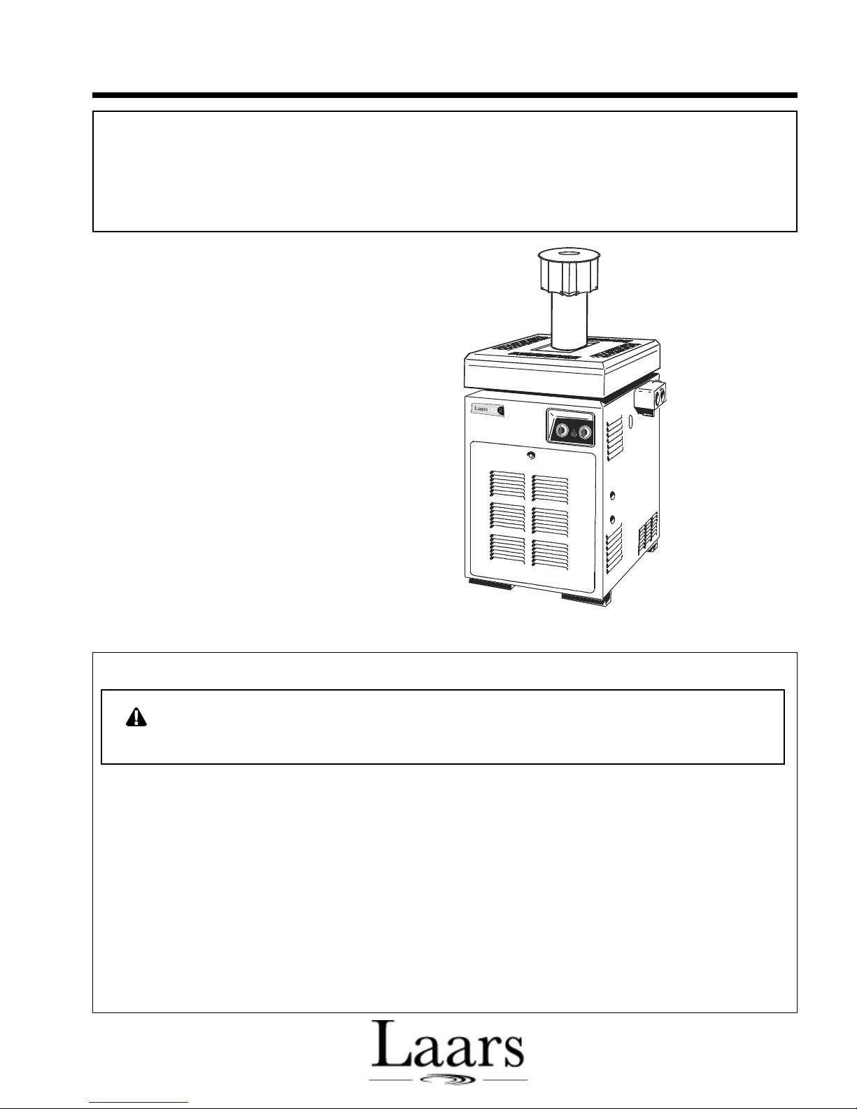
Installation and
Operation Manual
Laars Lite 2
™
Model LC (Australia)
Pool and Spa Heater
Natural Gas
Propane (Outdoor Only)
WARNING: If these instructions are not followed exactly, a fire or explosion
may result, causing property damage, personal injury, or death.
Do not store or use gasoline or other flammable vapors and liquids in the vicinity
of this or any other appliance.
Outdoor
Configuration
• Do not try to light any appliance.
• Do not touch any electrical switch; do not use any phone in your building.
• Immediately call your gas supplier from a nearby phone. Follow the gas
supplier’s instructions.
• If you cannot reach your gas supplier, call the fire department.
Installation and service must be performed by a qualified service technician.
H0216300B
WHAT TO DO IF YOU SMELL GAS

TABLE OF CONTENTS
SECTION 1.
General Information
1A. Introduction................................................... 1
1B. Description ................................................... 1
1C. Warranty....................................................... 1
SECTION 2.
Installation Instructions
2A. General Information ..................................... 1
2B. Outdoor Installation ..................................... 2
2B-1. Heater Clearance ......................................... 2
2C. Indoor Installation ......................................... 3
2C-1. Heater Clearance ......................................... 3
2C-2. Combustion and Ventilation Air Supply ........ 4
2D. Gas Supply and Piping ................................. 4
2E. Electric Wiring .............................................. 4
2E-1. Auxiliary Time Clock Wiring ......................... 4
2E-2. Remote Operation ........................................ 5
2F. Water Piping ................................................ 5
2G. Pressure Relief Valve................................... 6
2H. Pressure Switch............................................ 6
2J. Pressure Switch Adjustment......................... 6
2K. Automatic Chlorinators ................................. 6
2L. Temperature Rise ......................................... 7
SECTION 4.
Maintenance
4A. General ..................................................... 12
4B. Gas Pressure Tests................................... 12
4C. Electrical Troubleshooting......................... 13
4C-1. Control System Troubleshooting Sequence ... 13
4D. Gas Valve Replacement ........................... 20
4E. Gas Burner Removal ................................ 20
4E-1. Pilot Burner Removal ................................ 21
4F. Heat Exchanger Water Passages Inspection . 21
4G. Cleaning the Heat Exchanger ................... 22
4H. Automatic Flow Control Valve .................. 22
SECTION 5.
Assembly Instructions
5A. Reversible Water Connections ................. 23
SECTION 6.
LLC (Australia) Parts List
Exploded View of Heater...........................26
Parts List and Numbers.............................27
6A. Capacities and Dimensions....................... 28
SECTION 3.
Operating Instructions
3A. Start-Up Procedure ...................................... 8
3B. Temperature Controls .................................. 8
3C. Lighting and Shutdown ................................. 9
3C-1. Lighting the Heater ....................................... 9
3C-2. Filter Pump Operation .................................. 9
3C-3. Shutdown...................................................... 9
3D. Spring and Autumn Operation ...................... 9
3E. Winterizing ................................................. 10
3F. Water Chemistry ........................................ 10
3F-1. For Pool ...................................................... 10
3F-2. For Spa ....................................................... 10
3F-2a. Corrosion .................................................... 10
3F-2b. Testing........................................................ 10
3G. Therapeutic Spa Safety Rules.................... 11
3H. Swimming Pool Energy Saving Tips .......... 11
3J. Periodic Inspection ..................................... 12
Model LC (Australia) Pool and Spa Heater
Page 1
SECTION 1.
General Information
1A. Introduction
This manual provides information for the proper
installation, operation and maintenance of the Laars
Lite 2 Model LC (Australia) pool heater. The heater is
approved by the Australian Gas Association for use
with natural and propane gases. Installation should be
carried out in accordance with these instructions, the
gas authority and local government regulations.
The Installation, Operation, and Maintenance
manual must be followed exactly.
1B. Description
The Model LC (Australia) gets electrical power
from an external 240 volt (V) source. The Model LC
(Australia) provides a dual thermostat Flex-Temp
control system for pool/spa combinations or preheat
convenience. All Laars Lite 2 Model LC (Australia)
heaters meet stringent energy requirements such as
those instituted by the United States which require
intermittent ignition devices.
Waterpik Technologies designed this appliance to
heat only fresh water swimming pools and spas. Do
not use it as a heating boiler or general service water
heater. For special applications, consult your Australian Waterpik Technologies dealer.
Waterpik Technologies ships the heater with the
water connections on the right side. It could be necessary, or helpful, to switch the connections to the left
side to improve access for service. Instructions for
making this change can be found in Section 5. The
procedure should only be done by authorized personnel.
1C. Warranty
Waterpik Technologies sells the Laars Lite 2
Model LC (Australia) heater with a limited factory
warranty. A copy of the warranty is on the back cover
of this manual and is included in the plastic bag.
The home owner should fill out the warranty
registration card included in the plastic bag and return
it to the Australian distributor.
The warranty does not cover damage caused by
improper installation or field modification, or to the
heat exchanger by corrosive water. Section 3F explains
proper pool water chemistry.
SECTION 2.
Installation Instructions
WARNING
Improper installation or maintenance can
cause nausea or asphyxiation from carbon
monoxide and flue gases which could result in
severe injury or death.
2A. General
All gas-fired products require correct installation to
assure safe operation. The requirements for pool
heaters include the following:
1. Appropriate site location (clearances).
2. Noncombustible surface.
3. Sufficient combustion air and ventilation air.
4. Adequate venting (products of combustion).
5. Properly sized gas pipe.
6. Adequate water flow.
Install the heater at least 1.5 meters (m) from the
inside wall of the pool or spa unless it is separated
from the pool or spa by a solid fence, wall, or other
permanent barrier.
The Gas Installation Code AG601 offers general
guidelines for combustion air, ventilation air, and
flueing. Follow these guidelines to make sure the
installation is safe and efficient.
Pick a heater location that will supply enough air
for proper flue clearance, and allow space for maintenance access. Recommended clearances are specified
in Section 2B and 2C.
Locate the heater in an area where condensate
leakage from the heater or connections will not damage
the area around the appliance or the structure. If such a
location cannot be avoided, install a suitable drain pan
under the heater. This pan must not restrict air flow.
Install the heater on a noncombustible surface.
That means a surface made up of steel, iron, brick, tile,
concrete, slate, glass or plaster.
You can install the heater on a combustible floor
by putting a noncombustible base under the heater. Do
not install heater on carpeting. Combustible floor is a
floor made of, or surfaced with wood, compressed
paper, plant fibres or other materials that will ignite
and burn.
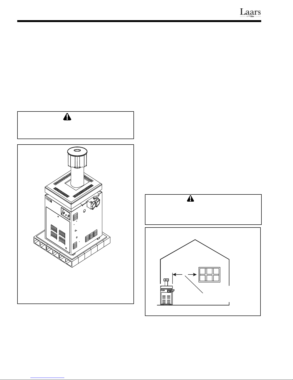
It is recommended that the noncombustible base
be a platform under the heater constructed of hollow
masonry no less than 100 millimeters (mm) thick,
covered with sheet metal at least 0.75 mm thick. The
masonry must be laid with ends unsealed, and joints
matched to provide a free circulation of air from side
to side through the masonry (see Fig. 1).
Page 2
Safe operation at the proper gas manifold pressure requires correct sizing of supply gas pipe. The
Gas Installation Code AG601 also offers general
criteria for gas piping (see Section 2D).
If the above installation requirements are not
followed, the fuel used in these appliances could
produce and expose you to substances that are known
to cause cancer or reproductive harm.
Install the heater in accordance with all local
codes and ordinances and the most recent edition of the
Gas Installation Code AG601.
Do not operate this heater outdoors at temperature below -7°C.
WARNING
The heater must be tested to ensure
operation is satisfactory before the installer
leaves.
2B. Outdoor Installation
2B-1. Heater Clearance
Locate the heater in an open, unroofed area, (see
Fig. 2) and maintain the following clearances:
Blank side and 150 mm Minimum
rear of heater
Piping side 300 mm Minimum
Front of heater 450 mm Minimum
Floor Noncombustible*
*If you are installing the heater on a combustible
surface, use an approved noncombustible base.
Do not install the heater in a location where
leaves or other combustible materials can gather
around the base or on the top.
Do not locate the heater close to sprinklers; the
water could damage the controls and the electronics.
If you are installing the heater under an overhang,
there must be a minimum clearance of 1.5 meters
above the top of the heater. The area under the overhang must be open on three sides. Protect the heater
from direct water drainage.
Notes:
1. Blocks must provide solid base and be braced so they
cannot slip out of place.
2. Air openings in blocks must be arranged to provide
unrestricted opening through entire width or length of
base.
Figure 1. Non-Combustible Platform
Special Precautions for Propane Gas Heaters
Propane gas is heavier than air, so do not
install pool heater using propane gas in pits or other
locations where gas might collect. Locate the heater a
safe distance from propane gas storage and filling
equipment. Consult local codes and fire protection
authorities about specific installation restrictions.
WARNING
Minimum clearances between the heater and
any opening into the building must be
maintained.
Size 12 5-500 mm
All O ther Sizes - 1500 mm
Figure 2. Outdoor Heater Locations
IMPORTANT: High wind conditions may
cause downdrafting problems in the heater. To minimize downdrafting problems in high wind areas, locate
the heater at least 900 mm from vertical surfaces, such
as nearby buildings and walls.
Model LC (Australia) Pool and Spa Heater
Page 3
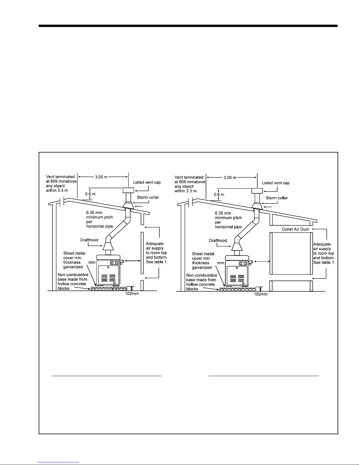
2C. Indoor Installation
The Laars Lite 2 Model LC (Australia) heater is
design-certified for indoor installation only when
equipped with a draft hood. Check the rating plate or
the parts list (Section 6) for the correct Laars draft
hood part numbers. Install the draft hood without
modification.
Connect the draft hood to a vent pipe which stops
at least 0.6 m above the highest point of the roof or
other object that is within 3 m of the flue. Install a
listed cap which allows a full equivalent opening for
flue products (see Fig. 3).
Roof jack
2C-1. Heater Clearance
Top of Heater 1.1 m Minimum
Blank side and 150 mm Minimum
rear of heater
Piping side 300 mm Minimum
Front of heater 450 mm Minimum
Floor Noncombustible*
*If you are installing the heater on a combustible
surface, an approved noncombustible base must be
installed.
Roof jack
305 mm of
0.75
NOTE:
1. The draft hood must sit directly on top of the heater as shown and must not be altered in any manner.
2. An approved flue cowl must be fitted.
3. Use approved roof fitting.
300 mm
Piping side
150 mm
Blank side
& Rear
Table 1. Direct Air Openings
Required Net Free Opening Area (cm2)
Directly from Outside
Model At Top At Bottom
125 393 393
175 552 552
250 789 789
325 1023 1023
400 1260 1260
305 mm of
0.75
300 mm
Piping side
150 mm
Blank side
& Rear
Table 2. Ducted Air Openings
Required Net Free Opening Area (cm2)
Ducted from Outside
Model At Top At Bottom
125 786 786
175 1104 1104
250 1578 1578
325 2046 2046
400 2520 2520
Figure 3. Indoor Installation Venting and Flueing
Page 4
2C-2. Combustion and Ventilation Air
Supply
All indoor installations must have openings to
outside air for combustion and ventilation. Tables 1
and 2 (see Fig. 3) show the net free opening areas
required at both ceiling and floor for the different
heater sizes. Waterpik Technologies does not recommend indoor installations that do not provide combustion air from outside the building.
NOTE: Check with louver manufacturers for Net
Free Area of louvers. Correct for screen resistance to
the Net Free Area if a screen is installed. Check all
local codes applicable to combustion air.
If the heater is installed in a residential garage,
the burners must be 450 mm above the garage floor.
See the Gas Installation Code AG601 for more information.
Warning
The conversion of this appliance from natural
gas to propane gas, or propane to natural,
must be done by an authorized person.
Waterpik Technologies provides kits and
detailed instructions for converting the heater.
Manual Shutoff
Valve
Gas Supply
Inlet
T-Fitting
75 mm Min.
Cap
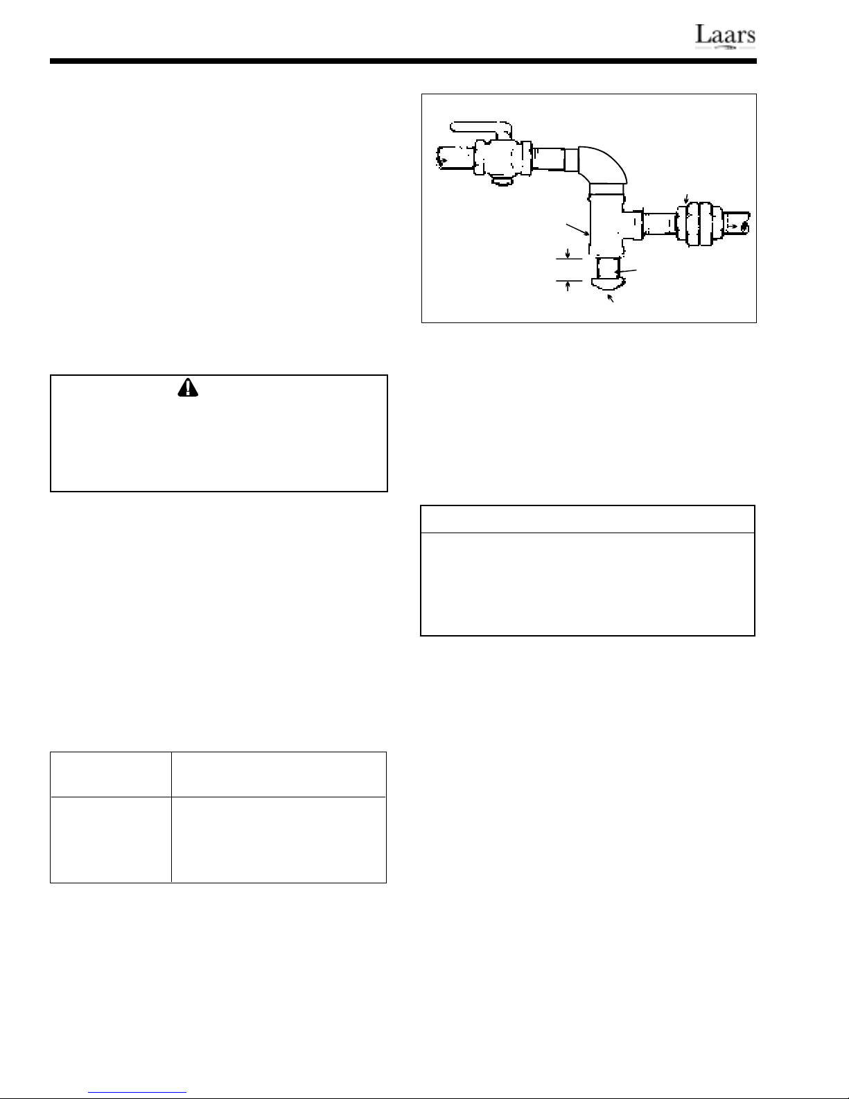
Figure 4. Proper Design For Sediment Trap / Drip Leg
Nipple
Union
To
Equipment
Inlet
testing if the test pressure is higher than 1/2 psig (3.7
kPa). If the test pressure is equal to or less than 1/2
psig (3.7 kPa), close the manual shut-off valve on the
heater during the piping pressure test.
If the supply gas pressure (Table 4) is less than
required, check for undersized pipe between the meter
and the heater, a restrictive fitting, or an undersized
gas meter.
Table 4. Supply Gas Pressure
2D. Gas Supply and Piping
Heaters shipped from the factory are certified to
operate at an altitude of zero to 600 m for natural gas,
to 1500 m for propane gas. The heater rating plate is
marked for use at specific altitudes.
If the supply gas pressure is less than required,
check for undersized pipe between the meter and the
heater, a restrictive fitting, or an undersized gas meter.
Waterpik Technologies recommends the gas inlet
pipe sizes in Table 3. Check local codes for compliance before installing the heater.
Table 3. Recommended Gas Inlet Pipe Sizes
Heater Distance from the meter
Size
125 20 mm 25 mm 32 mm
175 25 mm 32 mm 32 mm
250 & 325 32 mm 32 mm 40 mm
400 32 mm 40 mm 50 mm
NOTE: For propane gas, use one size smaller pipe except
on Model 125 which requires 20 mm from 0 to 15 m.
Install a union on the gas supply line outside the
heater jacket, including a drip leg and a manual shutoff valve (see Fig. 4). Do not use a restrictive gas cock.
Before operating the heater, test all gas connections for leaks with a soap solution. Do not use an
open flame. Disconnect the heater and its individual
shut-off valve from the gas piping during pressure
0 to 15 m 16 to 30 m 31 to 60 m
Minimum Maximum
Natural Gas 1.13 kPa 2.5 kPa
Propane Gas 2.50 kPa 3.5 kPa
NOTE: The minimum value listed for input adjustment.
Do not exceed the maximum supply pressure.
2E. Electric Wiring
The unit is fitted with a flexible electric cord and
3-pin plug for connection to a 240V 10 ampere (A)
power outlet. The power outlet must be effectively
earthed. See Figure 5 for the Model LC (Australia)
heater wiring.
NOTE: The pool heating system must have a manual
reset high limit installed in accordance with AS2610,
Section 2.7 (see Fig. 9). Contact a local installer or
distributor.
NOTE: No external junction box is required.
2E-1. Auxiliary Time Clock Wiring
If you install a time clock to control the filter
pump operation, the clock should have its own low
voltage (Fireman's) switch that turns off the heater
before turning off the pump. The switch should shut
off the heater about 15 minutes before the filter pump
shuts off.
Model LC (Australia) Pool and Spa Heater
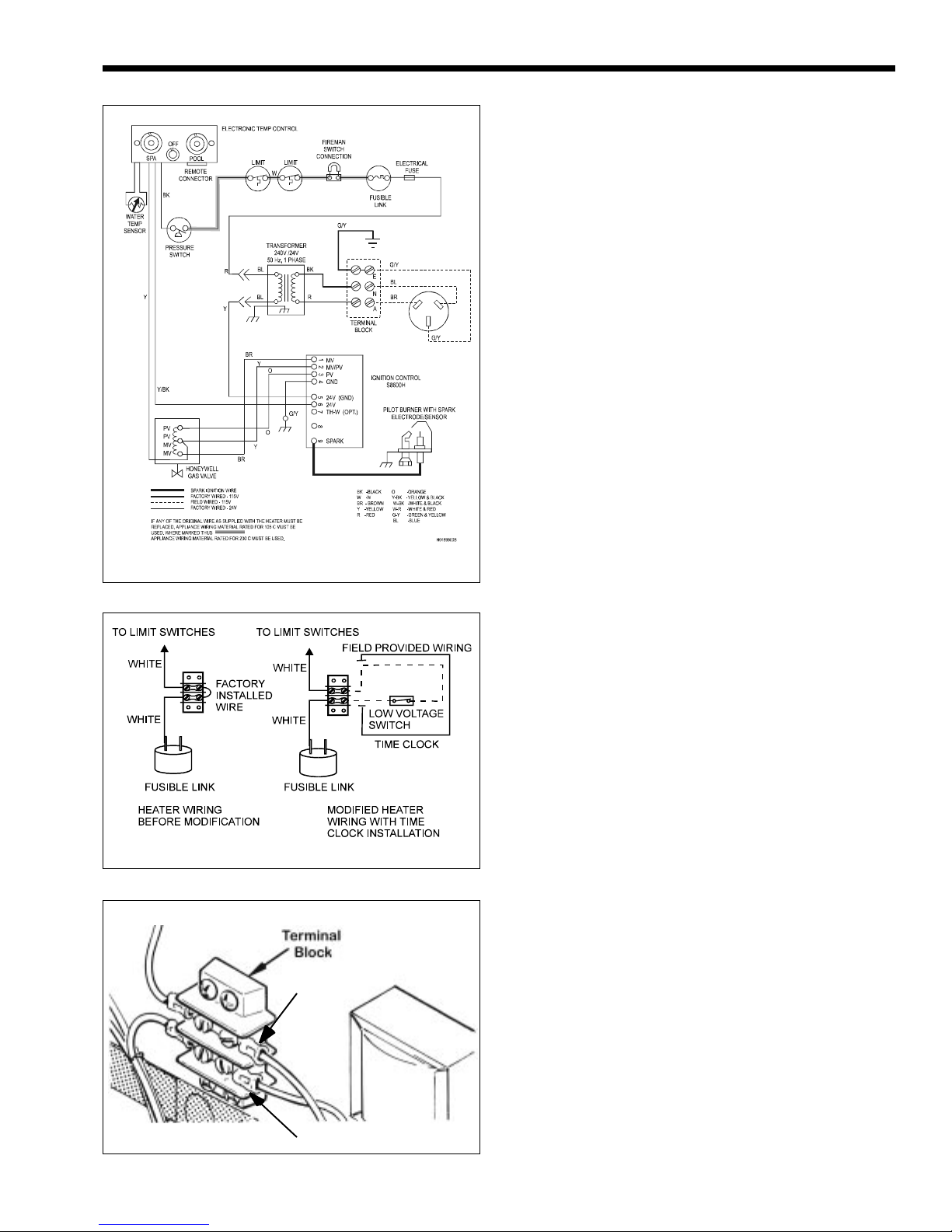
Figure 5. LC Wiring Diagram
Page 5
To install a time clock switch into the heater
wiring, follow these steps (see Fig. 6):
1. Remove the heater door.
2. Remove the factory-installed wire between
terminals 1 and 2 on the terminal block (see Fig. 7).
3. Connect the wires from the time clock auxiliary switch to the two terminals. Use 14 gauge copper
wire with insulation at least 1.2 mm thick, and temperature rating of 221°F (105°C) or greater.
2E-2. Remote Operation
The Model LC (Australia) pool/spa heater
controls can be wired for remote operation. Two
Waterpik Technologies remote control models are
available through the local dealer or distributor. The
CS-07 remote control permits switching from one
temperature controller to the other and turning the
heater on and off from a remote location. The CS-08
includes the same features as the CS-07 plus a remote
temperature controller.
An interrupt (On-Off) type remote can be connected by removing the jumper wire on the terminal
block located in the control compartment (see Fig. 7)
and connecting the two wires from the remote to the
two terminals on the terminal block. This type of
remote control will turn the heater on or off, but will
not switch between the two temperature controllers on
the Flex-Temp control panel.
To connect a 3-wire remote (not supplied by
Waterpik Technologies), order a wire harness assembly (part No. E0120000) which connects to the FlexTemp control panel. Installation instructions are
included with the wire harness assembly.
Suggested Time Clocks: Intermatic or Paragon
Figure 6. Time Clock Wiring
Terminal 1
Terminal 2
Figure 7. Fireman's Switch Connection
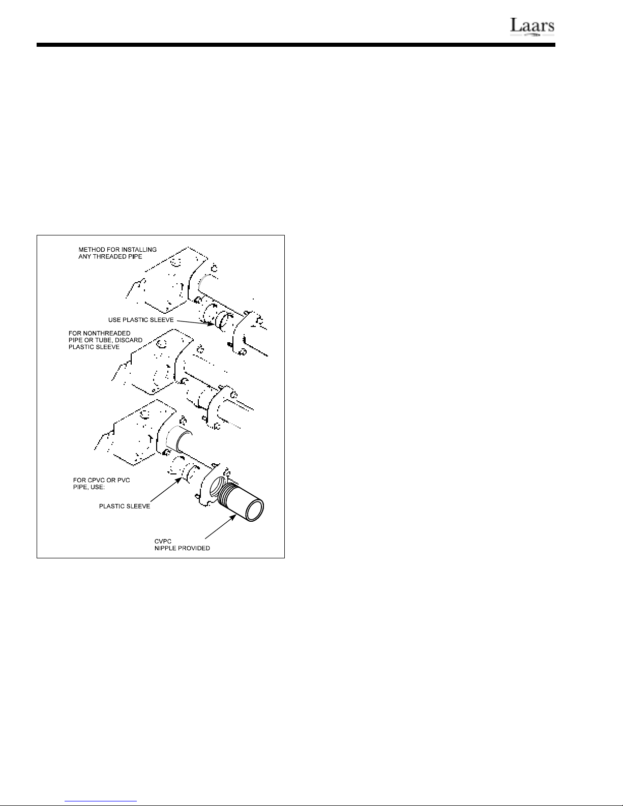
2F. Water Piping
The heater has 50 mm universal header
couplings. You can connect threaded 50 mm iron or
copper pipe, unthreaded 38 mm iron or copper pipe
using the special gaskets packaged with these
instructions, and CPVC pipe by first fitting the
CPVC nipples provided with the heater into the coupling
(see Fig. 8).
You can connect high-temperature plastic piping
(CPVC Schedule 80) to the inlet/outlet header if local
codes allow it, and the controls keep the filter pump
running at least 15 minutes after the heater is turned off.
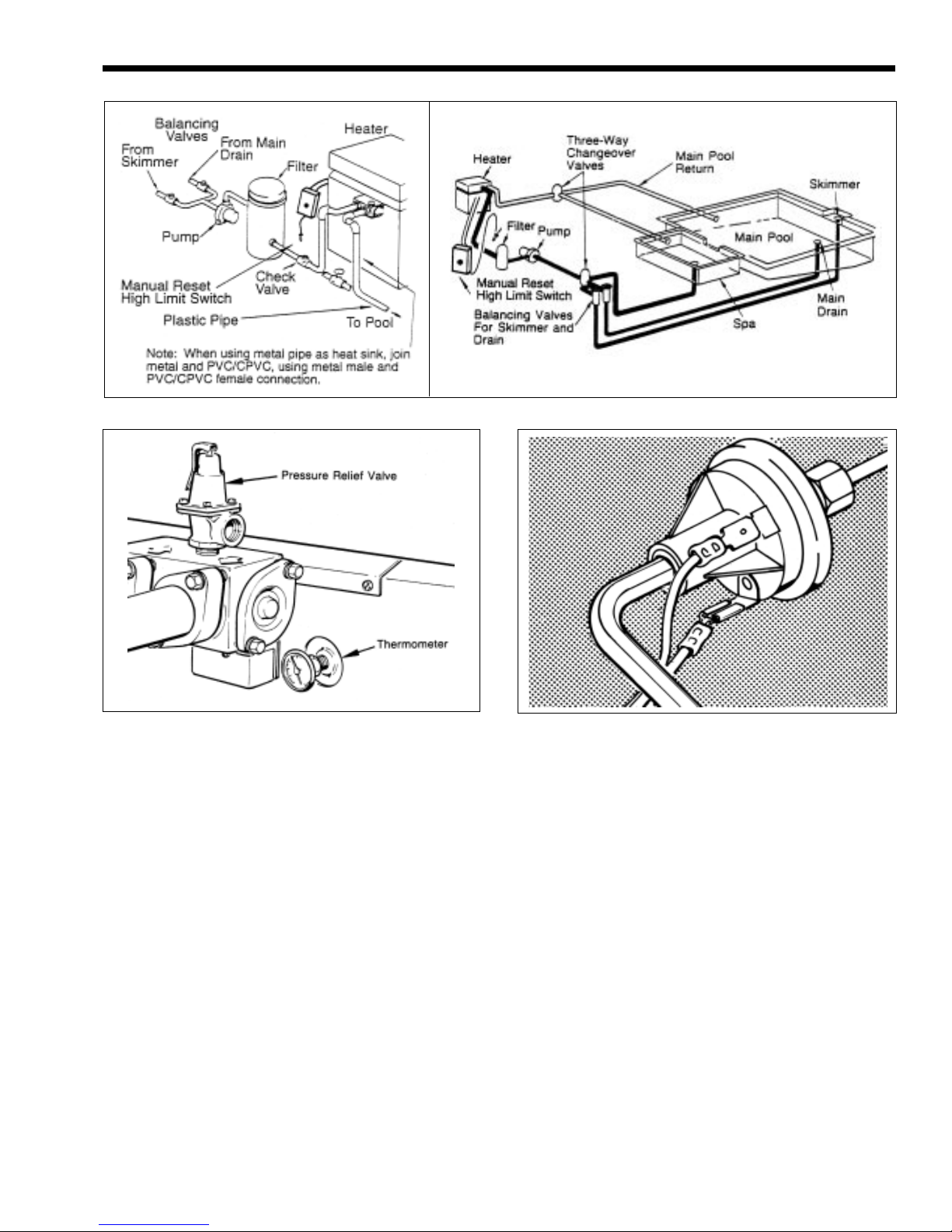
NOTE: Do not use PVC plastic materials in pipes,
fittings, grids and other elements of the filter system
unless a metal "heat sink" pipe is used between the
filter and the heater (see Fig. 9).
NOTE: The pool heating system must have a
manual reset high limit installed in accordance with
AS2610, Section 2.7 (see Fig. 9). Contact a local
installer or distributor.
Page 6
Install a check valve if there is any chance of
"back-siphoning" when the pump stops. Do not install
any other valve or variable restriction in the piping
between the heater outlet and the pool, unless it is
being used as a diverter valve.
2G. Pressure Relief Valve
A pressure relief valve is not supplied with the
heater, but local plumbing codes may require it. To
install a pressure relief valve, replace the 3/4" brass
plug on top of the input/output header with the valve
(see Fig. 10). The valve setting should be at or below
the maximum working pressure of any component in
the filter system
NOTE: Do not make the pressure switch adjustment if
the heater is installed more than 4.6 m below or 1.8 m
above the pool surface. Consult Waterpik Technologies for recommendations.
On some installations, the piping from the heater
to the pool is very short. The back pressure could be
too low to trigger the pressure switch. If this happens,
it may be necessary to install a directional fitting, or
elbows where the return line enters the pool. This will
increase back pressure enough for the heater to operate
properly.
2J. Pressure Switch Adjustment
The pool filter must be clean before making this
adjustment. The heater does not have to be firing.
1. Turn the rotary switch to OFF, and make sure the
pressure switch is at its lowest setting. This is
done by rotating the adjuster counter clockwise as
far as it will go (see Fig. 11).
2. Start the filter pump and confirm by means of
hearing an audible click or with an ohmmeter that
the pressure switch closes. If the switch fails to
close, replace it with a switch that has a lower
minimum setting.
Figure 8. Piping Connections
2H. Pressure Switch
The pressure switch is preset at the factory for
normal pool installations. Do not adjust the pressure
switch unless any of the following conditions exist:
1. If the top of the heater is 900 mm or more below
the surface of the pool.
2. If any part of the filter system piping is 900 mm
or more above the top of the heater jacket.
If either of these conditions exist, follow the
instructions in Section 2J.
3. Turn the adjuster clockwise to open the contacts
(see Fig. 11).
4. With the pump still running, reduce the pressure
setting 7 to 14 kPa psi to reclose the contact.
5. Turn off the pump and make sure the pressure
switch contacts open. The contact must open
right away when the pump shuts off.
It may be necessary to repeat these steps to get a
proper setting. The switch must be set so that the
heater will not fire unless the pump is running. If a
proper setting cannot be reached, contact the factory
service department.
Elevated spas are a special problem if the water
surface is more than 2.4 m above the heater, because
the pressure switch has a limit of 35 kPa. A special
pressure switch is available from the factory for these
installation.
When the water surface is more than a few feet
below the heater, use a pressure switch with a minimum setting of 7 kPa.
2K. Automatic Chlorinators
(Chemical Feeders)
A high concentration of chlorine (or other chemi-
cal) in the pool heater can be very destructive. Heater
damage caused by chemical concentration is not
covered by the Waterpik Technologies warranty. See
Section 3F for recommended levels.
Model LC (Australia) Pool and Spa Heater
Figure 9. Typical Installation
Page 7
Figure 10. Thermometer and Pressure Relief Valve
IMPORTANT: Equip the chlorinator with an
antisiphoning device so that chlorine will not siphon
into the heater after the pump shuts off.
Wire the chlorinator so it cannot operate unless
the filter pump is running. If the chlorinator has an
independent clock control, be sure the filter and
chlorinator clocks are synchronized.
If the chlorinator is equipped with its own pump,
install it so that it introduces the chlorine downstream
from the heater, and, if possible, below the level of the
heater outlet fitting.
2L. Temperature Rise
When the installation is complete, the installer
should take a temperature rise. Use the figures in Table
5 to confirm proper water flow through the heater.
An automatic, built-in bypass valve maintains
proper flow through the heater at flow rates up to 475
liters per minute (L/min). If the system filter-flow rate
is higher than 475 L/min, install a manual bypass
valve. Figure 9 shows a valve installed between the
Figure 11. Pressure Switch Adjustment
heater inlet and outlet. To set the bypass valve, follow
this procedure.
1. Clean the pool filter if necessary.
2. With the filter pump off, remove the drain valve
located on the right side of the inlet/outlet header.
Install a 1/4 inch Pete's plug and thermometer
(see Fig. 10).
3. Close the manual bypass valve.
4. Turn off the heater by moving the rotary switch
to OFF.
5. Start the filter pump.
6. After 3 minutes, note and record the thermometer
reading (this is pool water temperature).
7. Follow the procedures on the Lighting and
Shutdown label located inside the control compartment to turn the heater on.
8. Let the heater run for at least five minutes before
noting and recording the new thermometer
reading. The difference between this reading and
the first one is the temperature rise.
Page 8
9. If the temperature rise is outside the MIN-MAX.
numbers in Table 5, gradually open the bypass
valve until there is an acceptable temperature
rise.
10. Be sure the thermometer reading stays the same
for at least 3 minutes.
11. Once the temperature rise is correct, wire the
bypass valve in place to prevent tampering.
Table 5. Temperature Rise and Minimum
Flow Rates
TEMPERATURE RISE,°C MIN. FLOW
SIZE MIN. MAX. L/MIN
125 15 20 76
175 19 24 76
250 19 24 95
325 16 21 114
400 17 22 114
SECTION 3.
Operating Instructions
LIGHTING AND SHUTDOWN INSTRUCTIONS ARE
ON THE LABEL ATTACHED INSIDE THE CONTROL
COMPARTMENT DOOR.
WARNING
PROPANE GAS: To avoid possible injury, fire
and explosion, read and follow these
precautions and all instructions on this
appliance before lighting the pilot. If this
appliance uses Propane gas which is heavier
than air, it will remain at ground level if there is
a leak. Before lighting, sniff at ground level. If
you smell gas, follow these rules:
1. DO NOT light matches. DO NOT turn
electric lights or switches on or off in
area. DO NOT use an electric fan to
remove the gas from area.
2. Shut off gas at propane tank.
3. Telephone gas company and fire
department for instructions. Give your
name, address and phone number.
If your propane tank runs out of fuel, turn off
gas at the appliance. After the tank is refilled,
the appliance must be relit according to the
instructions located on the inside of the door.
DO NOT attempt repairs on the gas control or
appliance. Tampering is dangerous and voids
all warranties.
WARNING
Flue pipes, draft hoods and heater tops get
hot! These surfaces can cause serious burns,
so do not touch these surfaces while the
heater is in operation. Adding a flue cap
reduces the temperature on the top.
3A. Start-Up Procedure
With any new pool or spa installation, operate the
filter pump with the heater off long enough to completely clean the water. This will remove any installation
residue from the water. Make sure the filter is clean
before starting the heater.
When raising the temperature of a cold pool,
remove all time clock settings. This lets the filter system
and heater operate continuously until the water reaches
the temperature setting on the thermostat. When that
happens, the heater will automatically shut off, but the
filter pump will keep running. Even though the heater
will be operating, the outlet piping will not feel hot to
the touch.
NOTE: Keep all objects off the top of the heater.
Blocking air flow could damage the heater and void the
warranty.
3B. Temperature Controls
The temperature controls on the Model LC
(Australia) are calibrated at the factory, and cover a
range from 21°C to 40°C. Always use an accurate pool
thermometer to verify the actual pool water temperature. Once the correct position for the control knob is
found, use the TEMP-LOK to keep it from going any
higher by putting the tab next to the knob, then tightening the screw.
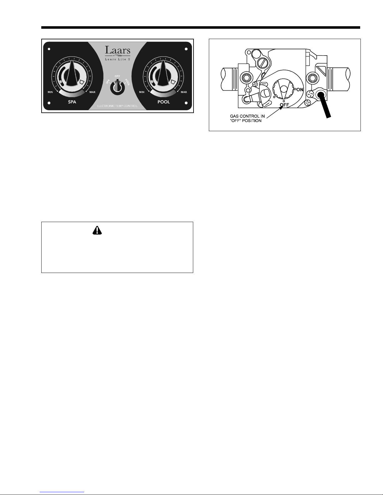
The heater has dual temperature controls which
allows two different temperature settings selected by
the rotary switch in the middle of the panel. The owner
can set one control for normal use and the other for
standby, or one can be set for a pool and the other for
a spa. Positioning the rotary switch in the middle turns
off the heater (see Fig. 12).
IMPORTANT: The temperature controls cannot be
calibrated in the field. If the control is faulty, shut
down the heater and replace the control according to
the instructions in Section 4. DO NOT use the rotary
switch to completely shut down the heater. Shut down
the heater completely by removing the access door and
turning the main gas valve OFF.
Model LC (Australia) Pool and Spa Heater
C
Figure 12. LC (Australia) Temperature Controls
3C. Lighting and Shutdown
3C-1. Lighting the Heater
Full lighting and shutdown instructions can also
be found attached to the inside of the control compartment door.
To restart the heater in the Spring, have a professional service technician reassemble the heater as
follows:
WARNING
For your safety when starting the heater, keep
your head and face well away from the lower
firebox opening to prevent any risk of personal
injury.
Turn off all electrical power to the heater at the
main junction box. Open the control compartment door
and turn the gas valve OFF. Turn the rotary switch on
the temperature control panel OFF. WAIT FIVE
MINUTES BEFORE TRYING TO LIGHT THE
HEATER.
The LC (Australia) heater does not need manual
pilot lighting. It is done automatically by the ignition
control when the thermostat calls for heat.
1. Turn the gas valve control knob counter-
clockwise to ON (Fig. 13).
2. Replace the control compartment door.
Page 9
Figure 13. LC (Australia) Gas Valve
On propane heaters, if the pilot does not ignite
within 15 seconds, the system locks out and turns off
power to the whole system.
To check the lockout on the ignition control, turn
the gas valve knob OFF. Set the thermostat to call for
heat. Sparking occurs after a few seconds, but since
there is no supply gas, the pilot cannot light. Sparking
continues for about 15 seconds until lockout occurs
and the ignition control shuts down the system. To
reactivate the system, turn the thermostat to its lowest
setting, wait 10 seconds, then turn the thermostat to its
original setting.
1. Turn the gas valve knob to ON.
2. Replace the control compartment door.
3. Position the rotary switch to ON and follow
the lighting instructions above.
3C-2. Filter Pump Operation
The filter pump must continue running for at
least 15 minutes after the heater shuts off to prevent
damage to the system piping.
3C-3. Shutdown
For a complete shutdown, turn the switch on the
control panel to OFF, turn off all electrical power to
the heater at the main junction box, and set the thermostat to its lowest setting. Open the control compartment
door and turn the gas valve knob clockwise to OFF.
Turn any external gas valves OFF.
3. Turn on electrical power to the heater.
4. Turn on the filter pump.
5. Set the appropriate temperature control to the
desired setting, and turn the rotary switch to
that control. Until the water reaches a temperature of about 21°C, it is normal to have some
water accumulating in the base of the heater.
6. Set the time clock if one is installed.
3D. Spring and Autumn Operation
During periods of cold but not freezing weather,
turn the temperature control counterclockwise to the
MIN setting. This will prevent damage, yet still permit
bringing the pool water back up to the desired temperature in the least amount of time.
In areas subject to only short freeze periods, turn
off the heater and run the filter pump continuously for
the length of the cold period.
If the pool is not going to be heated for a long
period, shut the heater off (see Section 3C-3).
 Loading...