

Page 1
Installation and Operation Instructions Document 1318G
Installation and Operation
Instructions for
THE
FT
SERIES
Wall-Mounted, Modulating
Gas, Condensing, Combination Boiler
Model FTCW
140,000 BTU/hr
199,000 BTU/hr
• Natural Gas (NG) - Factory Conguration
• Propane Gas (LP) - Field-Convertible
FOR YOUR SAFETY: This product must be installed and serviced by a professional service technician,
qualied in hot water boiler and heater installation and maintenance. Improper installation and/or operation
could create carbon monoxide gas in ue gases which could cause serious injury, property damage, or
death. Improper installation and/or operation will void the warranty.
AVERTISSEMENT
WARNING
If the information in this manual is not
followed exactly, a re or explosion may
result causing property damage, personal
injury or loss of life.
Do not store or use gasoline or other
ammable vapors and liquids in the vicinity of
this or any other appliance.
WHAT TO DO IF YOU SMELL GAS
• Do not try to light any appliance.
• Do not touch any electrical switch; do not
use any phone in your building.
• Immediately call your gas supplier from a
nearby phone. Follow the gas supplier's
instructions.
• If you cannot reach your gas supplier, call
the re department.
Installation and service must be performed
by a qualied installer, service agency, or gas
supplier.
Assurez-vous de bien suivres les instructions
données dans cette notice pour réduire au
minimum le risque d’incendie ou d’explosion
ou pour éviter tout dommage matériel, toute
blessure ou la mort.
Ne pas entreposer ni utiliser d’essence ou ni
d’autres vapeurs ou liquides inammables dans
le à proximité de cet appareil ou de tout autre
appareil.
QUE FAIRE SI VOUS SENTEZ UNE ODEUR DE
• Ne pas tenter d’allumer d’appareils.
• Ne touchez à aucun interrupteur. Ne pas vous servir
des téléphones dans le bâtiment où vous vous
trovez.
• Appelez immédiatement votre fournisseur de
gaz depuis un voisin. Suivez les instructions
du fournisseur.
• Si vous ne pouvez rejoindre le fournisseur de
gaz, appelez le sservice des incendies.
L’installation et l’entretien doivent être assurés par
un installateur ou un service d’entretien qualié
ou par le fournisseur de gaz.
GAZ:
H2372800G
Page 2

TABLE OF CONTENTS
SECTION 1 Product Accessories
1.1 Introduction ..........................................................3
1.2 Included with the Unit .........................................3
SECTION 2 Product Characteristics
2.1 Model Nomenclature (model number) ................. 5
2.2 Specications ......................................................6
2.3 Dimensions .........................................................8
2.4 Names of Components ......................................10
2.5 Product Flow Paths and Characteristics ............12
2.5.1 Central Heating ow.. .......................................12
2.6 Product Flow Paths and Characteristics ............13
2.6.1 Domestic Hot Water ow. . ................................13
SECTION 3 Safety Regulations
3.1 Safety Symbols ..................................................14
3.2 Safety Precautions and Proper Use ..................16
SECTION 4 Installation
4.1 Location and Clearances ...................................18
4.2 Wall Mount Bracket ............................................19
4.3 Combustion Air .................................................. 20
4.3.1 Combustion Air from Room ...............................20
4.3.2 Ducted Combustion Air ...................................... 20
4.4 Venting (Exhaust) .............................................. 22
4.5 General Location Guideline ............................... 23
4.6 Locations for Vent Pipe Terminator .................... 24
4.6.1 Direct Venting Clearances ................................24
4.6.2 Venting Requirements in the
Commonwealth of Massachusetts
4.7 Common Vent Test ............................................26
4.8 Air Supply and Vent Connections ......................27
4.8.1 Vent / Air Pipe Lengths ......................................27
4.8.2 Indoor Combustion Air .......................................28
4.9 Vent / Air Pipe Termination.................................28
4.10 Gas Supply and Piping ...................................... 31
4.11 Gas Supply Pressure ......................................... 34
4.12 Adjusting Combustion ........................................ 35
4.13 High Altitude Installations. .................................36
4.14 Natural Gas to Propane Conversion .................. 37
4.15 Plumbing Guidelines .......................................41
4.15.1 External Plumbing and
Water Connection Guidelines
4.15.2 Applicable Backow Preventer ..........................41
4.15.3 Diaphragm type Expansion tank ........................41
4.15.4 Zoning with zone valves ....................................42
..................... 25
............................41
4.15.5 Zoning with circulation pumps ...........................43
4.16 Pressure Relief Valve ........................................44
4.17 Disposal of Condensate ....................................45
4.18 DHW Flow Restrictors ......................................46
4.19 Electrical Wiring Connections ............................47
4.20 DIP Switches .....................................................48
4.21 Control Board, Electrical Diagram ....................49
4.22 Ladder Diagram .................................................50
4.23 Electrical Connections ....................................... 51
SECTION 5 Control Display and Operation
5.1 Control Dial and Buttons .................................... 53
5.2 LCD Overview ..................................................54
5.3 Operating Mode .................................................55
5.4 Status Display Mode .......................................... 56
5.5 DHW Set Point Change Mode ..........................57
5.6 CH Set Point Change Mode ..............................58
5.7 Storage Mode .................................................... 58
5.8 Installer Parameters ..........................................59
5.9 Outdoor Reset Adjustment ................................61
5.10 External Set Point Temperature Control ............61
5.11 Error Mode ......................................................... 62
SECTION 6 Error Codes
6.1 Error Code Tables .............................................63
6.2 Fault Tree Analysis ...........................................66
SECTION 7 Trouble Shooting
7.1 Diagnostics ........................................................ 68
7.2 Suggested Corrective Actions ...........................69
SECTION 8 Maintenance
8.1 Annual startup & general maintenance .............71
8.2 Flushing the Combination Boiler ........................ 73
8.3 Draining and Cleaning ...................................... 74
8.4 Freeze Protection ..............................................74
SECTION 9 Installation Check
9.1 Quick View ......................................................... 75
9.2 Final Check Lists ...............................................76
SECTION 10 Parts List and Illustrations
10.1 FT 140 ...............................................................78
10.2 FT 199 ...............................................................85
Page 3
The FT Series Wall Mounted, Combination Boiler
SECTION 1 Product Accessories
1.1 Introduction
This manual provides information necessary for the
installation, operation, and maintenance of the FT Series
Wall Mounted, Combination Boiler. All application
and installation procedures must be read and reviewed
completely before proceeding with the installation. Consult
the factory, or your local factory representative, with any
problems or questions regarding this equipment. Experience
has shown that most operating problems are caused by
improper installation.
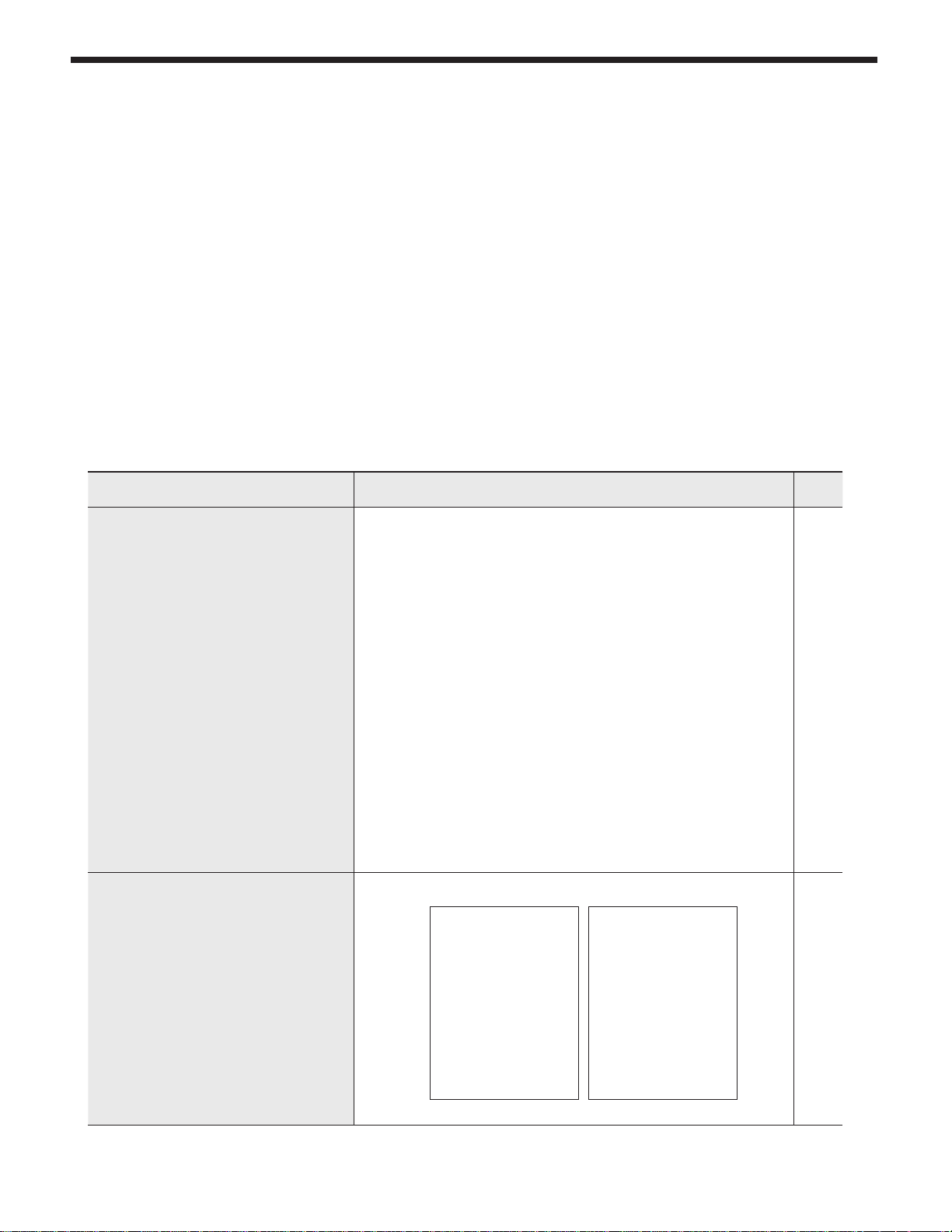
1.2 Included with the Unit
Item Description Qty
All installations must be made in accordance with
1) American National Standard Z223.1/NFPA54-Latest Edition
“National Fuel Gas Code” or
2) CSA B149.1 “Natural Gas and Propane Installation Code”
and with the requirement of the local utility or other authorities
having jurisdiction. Such applicable requirements take
precedence over the general instructions contained herein.
All electrical wiring is to be done in accordance with the
local codes, or in the absence of local codes, with: 1) The
National Electrical Code ANSI/NFPA No. 70-latest Edition, or
2) CSA STD. C22.1 “Canadian Electrical Code - Part 1”. This
appliance must be electrically grounded in accordance with
these codes.
Page 3
Wall Mounted,
Combination Boiler
FTCW140 / 199
Installation Instructions and
User’s Manual
1
THE
FT
THE
FT
1
Page 4

Page 4
1.2 Included with the Unit (continued)
Items Descriptions Qty
Condensate Hose 1
FT1894
Wall Mount Bracket 1
2 types of Wall Anchors
Pressure Relief Valve
(CH LINE 3/4˝ 30psi)
Model: CASH ACME F-82
3” Mesh Screens 2
O-Ring and Gasket Kit 1
Outdoor Sensor
with screws and anchors
4
FTCW140 FTCW199
4
1
1
4.5 GPM Flow Restrictor
(dark blue)
Propane Conversion Orice 1
*
A 3.2 GPM Flow Restrictor (white) has been factory installed. See Section 4.17
Auto Fill Valve and Backow Preventer Valves are NOT included (Field Supplied).
*
N/A 1
Page 5
The FT Series Wall Mounted, Combination Boiler
SECTION 2 Product Characteristics
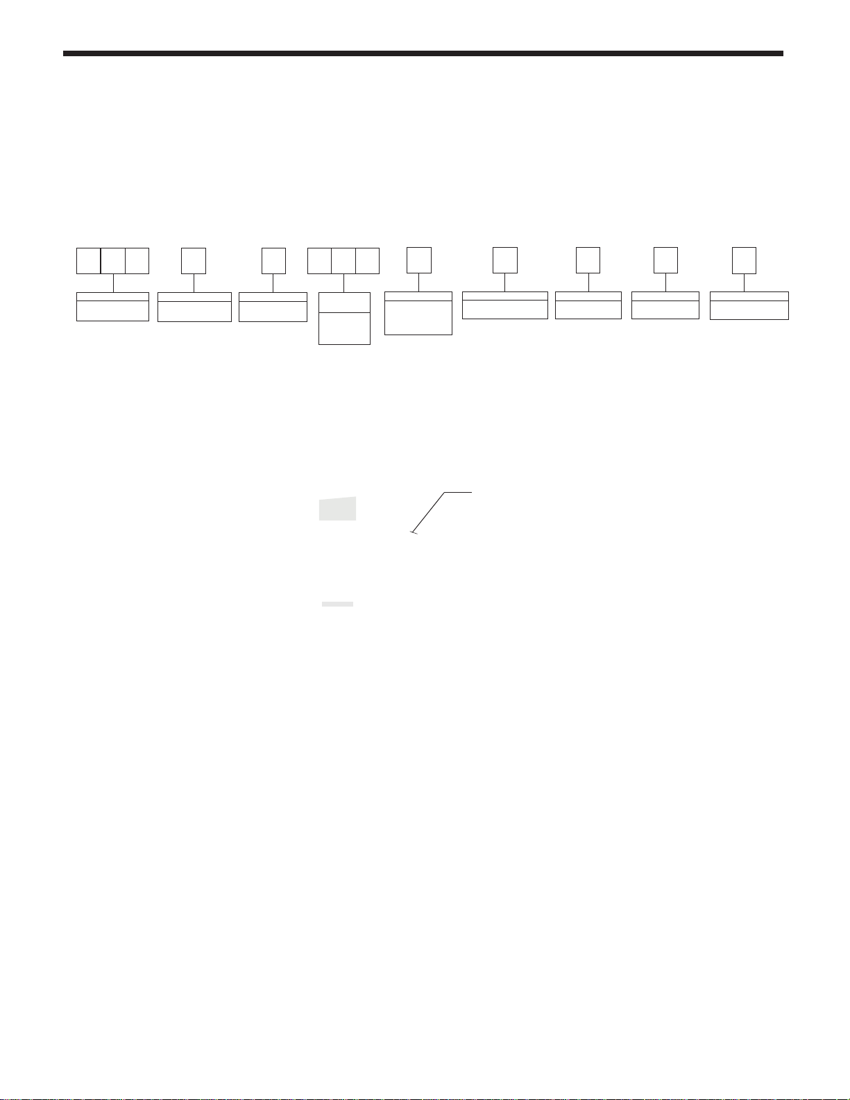
2.1 Model Nomenclature (model number)
The Model Nomenclature is shown on your Rating Plate and consists of a series of letters and numbers
( Nomenclature ) that further identies the characteristics of your FT.
2 3 4 5 6 7 8 9 10 11 12 13
1
F T C W A 1 X N
M
SERIES
FT
C - Combination
CONFIG
W - Wall Hung
SIZE
MBTU/h
140
199
FUEL
N - Natural
P - Propane
ALTITUDE
A -
0 -10,000 Feet
REVISION
1 -
First
OPTIONS
X - Standard
Page 5
PUMP
N - with Pump
MODEL NUMBER
Page 6
Page 6
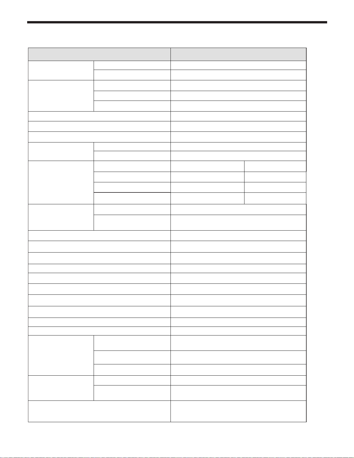
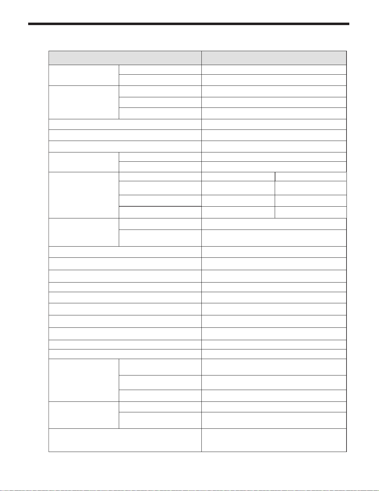
2.2 Specications
Model Name FTCW140
Gas Input Rate
Hot Water Capacity
Installation Indoor / Wall hung type
Flue System Sealed Combustion Direct / Single Vent / Concentric Vent
Vent Run 2˝(50ft*) , 3˝(100ft) Schedule 40 CPVC, PP, PVC
Gas Supply Pressure
Manifold Pressure
Power Supply
MAX 140,000 Btu/h
MIN 28,000 Btu/h
35°F Rise 7.1 GPM
45°F Rise 5.5 GPM
77°F Rise 3.2 GPM
NG 3.5˝ WC to 10.5˝ WC
LP 8.0˝ WC to 13˝ WC
Gas type NG LP
Vent size 2˝ or 3˝ VENT 2˝ or 3˝ VENT
”
Max Fire -0.216
Min Fire 0.002” WC 0.079” WC
Main Supply 120V 60Hz / 4A
Maximum Power
Consumption
160W
WC -0.216” WC
Ignition System Direct Electronic Ignition / Automatic Flame Sensing
Burner System Single Orice Premixed Fuel Modulation
Gas Valve System Combination modulating (Current proportional)
Minimum Flow Rate 0.5 GPM
Dimensions W17.25˝ - H29.0˝ - D15.5˝
Shipping Weight 111 lbs (50 kg)
Sub Heat Exchanger Water Capacity(DHW) Under 1 Gallon
Main Controller / Control Panel NGTX-900CP / P-920C
Domestic Hot Water Pressure, DHW Min 15 ~ Max 150 PSI
Central Heat Water Pressure, CH Min 15 ~ Max 30 PSI
Connection Sizes
Materials
Cold Water Inlet / Hot Water
Outlet
(CH) Space Heating Supply/Re-
turn
Gas Inlet 3/4˝ NPT
Casing Cold Rolled Carbon Steel
Heat Exchanger
3/4˝ NPT
1˝ NPT
Primary Heat Exchanger : Stainless Steel
Sub Heat Exchanger : Stainless Steel
Flame Rod, Overheat Cut O Device, Gas Valve Opera-
Safety Devices
tion Detector, Exhaust Temperature High Limit Switch,
Water Temperature High Limit Switch
* Allowable 2” vent length for propane is 25’
Page 7
The FT Series Wall Mounted, Combination Boiler
2.2 Specications (continued)
Model Name FTCW199
Page 7
Gas Input Rate
Hot Water Capacity
Installation Indoor / Wall hung type
Flue System Sealed Combustion Direct / Single Vent / Concentric Vent
Vent Run 2˝(50ft*) , 3˝(100ft) Schedule 40 CPVC, PP, PVC
Gas Supply Pressure
Manifold Pressure
Power Supply
MAX 199,000 Btu/h
MIN 19,900 Btu/h
35°F Rise 9.88 GPM
45°F Rise 7.7 GPM
77°F Rise 4.8 GPM
NG 3.5˝ WC to 10.5˝ WC
LP 8.0˝ WC to 13˝ WC
Gas type NG LP
Vent size 2˝ VENT 3˝ VENT
-0.314
”
Max Fire
Min Fire -0.015”WC -0.015”WC
Main Supply 120V 60Hz / 4A
Maximum Power
Consumption
160W
WC -0.173”WC
Ignition System Direct Electronic Ignition / Automatic Flame Sensing
Burner System Single Orice Premixed Fuel Modulation
Gas Valve System Combination modulating (Current proportional)
Minimum Flow Rate 0.5 GPM
Dimensions W19.6” - H32.0” - D16.3”
Shipping Weight 130 lbs (59 kg)
Sub Heat Exchanger Water Capacity(DHW) Under 1 Gallon
Main Controller / Control Panel NGTX-900CP / P-920C
Domestic Hot Water Pressure, DHW Min 15 ~ Max 150 PSI
Central Heat Water Pressure, CH Min 15 ~ Max 30 PSI
Connection Sizes
Materials
Cold Water Inlet / Hot Water
Outlet
(CH) Space Heating Supply/Re-
turn
Gas Inlet 3/4˝ NPT
Casing Cold Rolled Carbon Steel
Heat Exchanger
3/4˝ NPT
1˝ NPT
Primary Heat Exchanger : Stainless Steel
Sub Heat Exchanger : Stainless Steel
Flame Rod, Overheat Cut O Device, Gas Valve Opera-
Safety Devices
tion Detector, Exhaust Temperature High Limit Switch,
Water Temperature High Limit Switch
* Allowable 2” vent length for propane is 25’
Page 8
Page 8
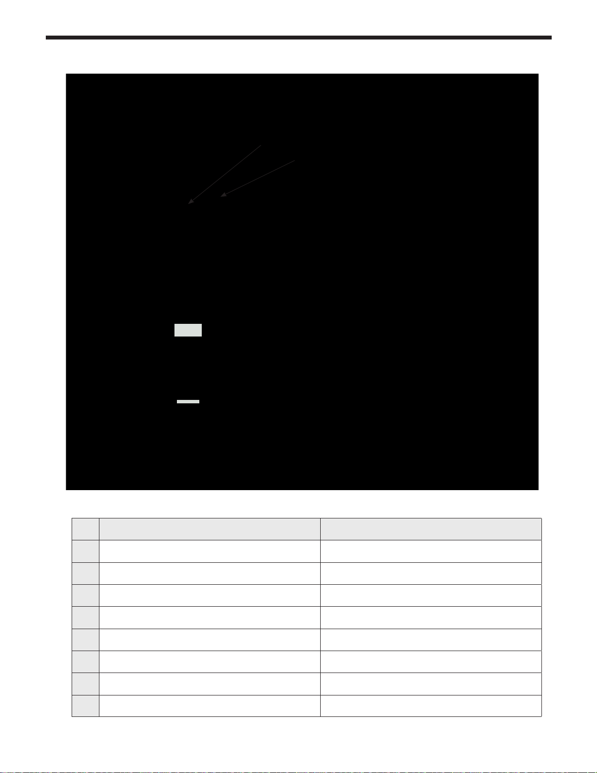
2.3 Dimensions FTCW140
Air Intake
Vent
Description Diameter
A Air Intake collar 3"
B Vent Pipe Collar 3"
C ‘CH’ Supply 1" NPT
D ‘CH’ Return 1” NPT
E ‘DHW’ Outlet 3/4” NPT
F ‘DHW’ Inlet 3/4” NPT
G Gas Inlet 3/4” NPT
H Condensate Line 1/2" NPT
Page 9
The FT Series Wall Mounted, Combination Boiler
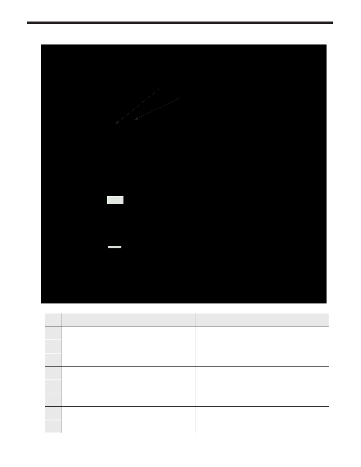
2.3 Dimensions FTCW199
Air Intake
Vent
Page 9
Description Diameter
A Air Intake collar 3"
B Vent Pipe Collar 3"
C ‘CH’ Supply 1" NPT
D ‘CH’ Return 1” NPT
E ‘DHW’ Outlet 3/4” NPT
F ‘DHW’ Inlet 3/4” NPT
G Gas Inlet 3/4” NPT
H Condensate Line 1/2" NPT
Page 10
Page 10
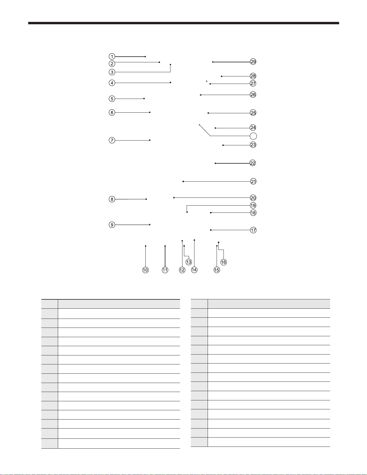
2.4 Names of Components
FTCW140
30
# Name of Component
1 Air Vent (air eliminator)
2 Pressure Relief Valve
3 Air Intake Collar
4 Air Gas Mixing Pipe
5 Gas Valve
6 DHW Water Tank
7 Main PCB
8 Manual Power Switch (ON / OFF)
9 Recirculation Pump DHW / CH Primary Pump
10 'CH' Supply Connection
11 'CH' Return Connection
12 CH Pressure Gauge
13 DHW Outlet Connection
14 Gas Inlet Connection
DHW Inlet Connection (lter and ow restrictor)
15
# Name of Component
16 Condensate Connection
17 Condensate Trap
18 Air Pressure Switch (condensate)
19 Mixing Valve
20 Terminal Block
21 Control Panel and Display
22 Heat Exchanger
23 Ignition Trans
24 Flame Detecting Sensor
25 Burner Case
26 BLDC Fan (Blower)
27 Vent Pipe
28 Air Pressure Switch
29 Vent Pipe Collar
30 Sight Glass
Page 11
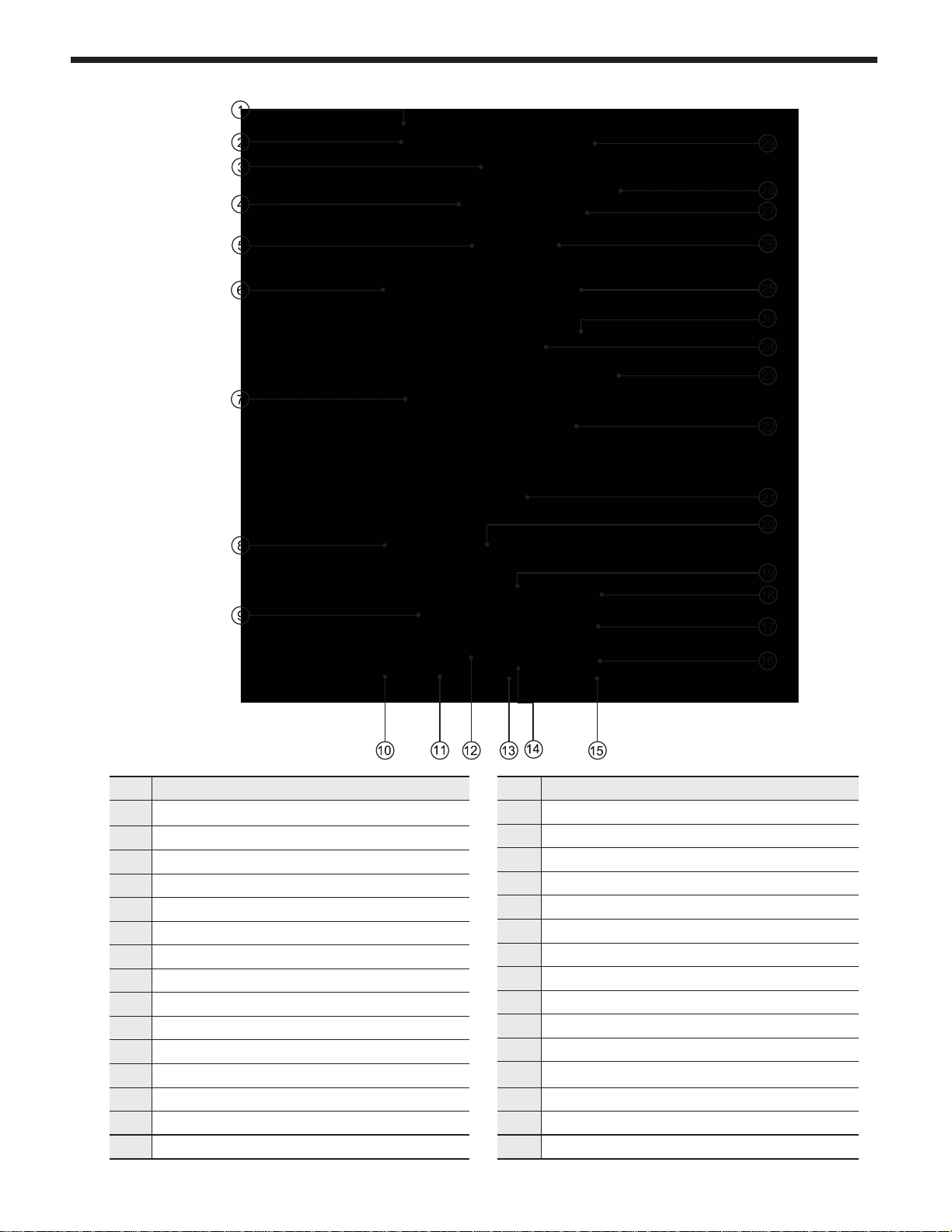
The FT Series Wall Mounted, Combination Boiler
FTCW199
Page 11
# Name of Component
1 Air Vent (air eliminator)
2 Pressure Relief Valve
3 Air Intake Collar
4 Gas Valve
5 Air Gas Mixing Pipe
6 DHW Water Tank
7 Main PCB
8 Manual Power Switch (ON / OFF)
9 Recirculation Pump DHW / CH Primary Pump
10 'CH' Supply Connection
11 'CH' Return Connection
12 CH Pressure Gauge
13 DHW Outlet Connection
14 Gas Inlet Adapter
DHW Inlet Connection (lter and ow restrictor)
15
# Name of Component
16 Condensate Connection
17 Condensate Trap
18 Air Pressure Switch (condensate)
19 Mixing Valve
20 Terminal Block
21 Control Panel and Display
22 Heat Exchanger
23 Ignition Trans
24 Flame Detecting Sensor
25 Burner Case
26 BLDC Fan (Blower)
27 Vent Pipe
28 Air Pressure Sensor
29 Vent Pipe Collar
30 Sight Glass
Page 12
Page 12
Vent
Combustion
Air
Vent
Combustion
Air
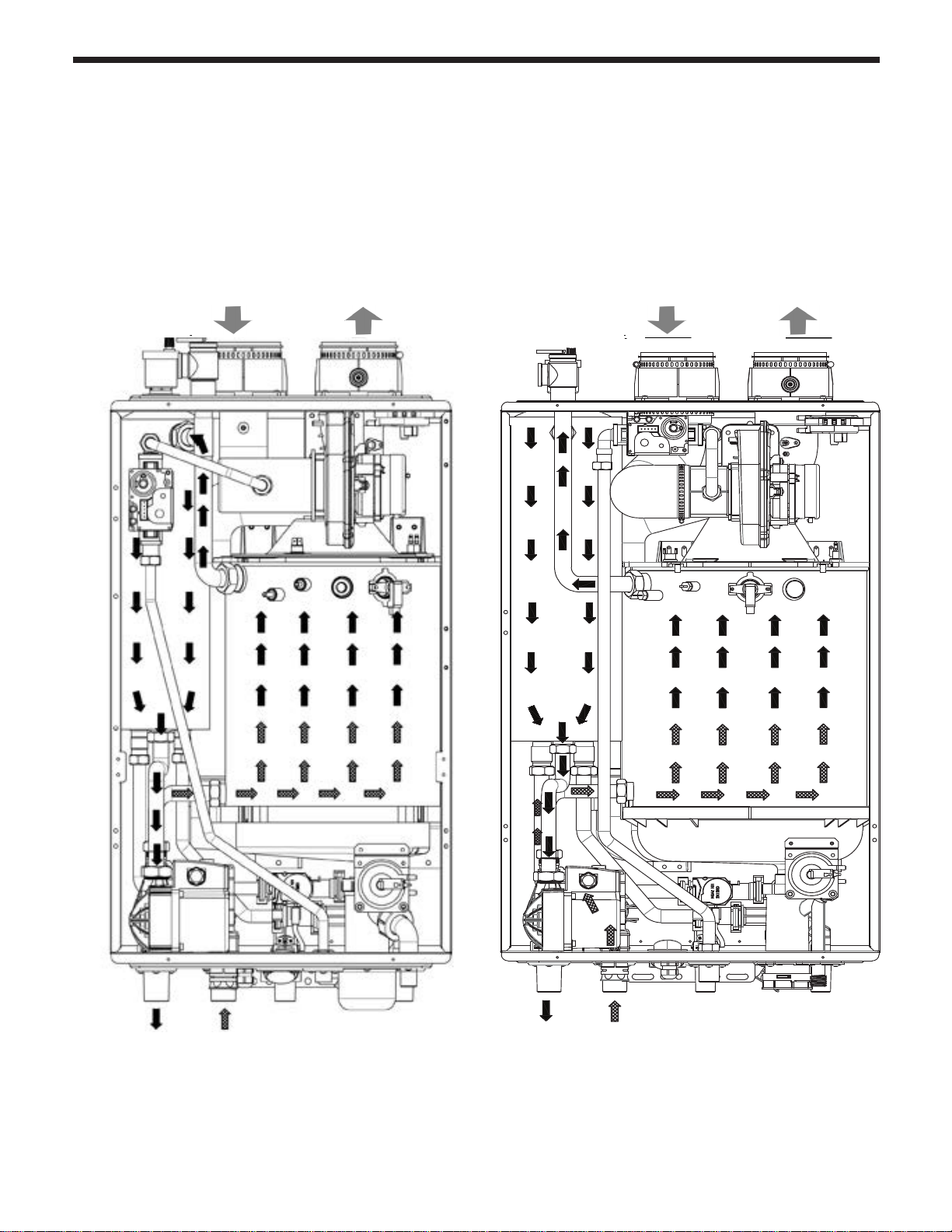
2.5 Product Flow Paths and Characteristics
2.5.1 Central Heating ow. Combination Boiler Heating Mode.
Water in the heating pipe is used for space heating.
FTCW140
Combustion
Air
Vent
FTCW199
Combustion
Vent
Air
CH Supply Hydronic Supply
CH Return Hydronic Return
Page 13
The FT Series Wall Mounted, Combination Boiler
Vent
Combustion
Air
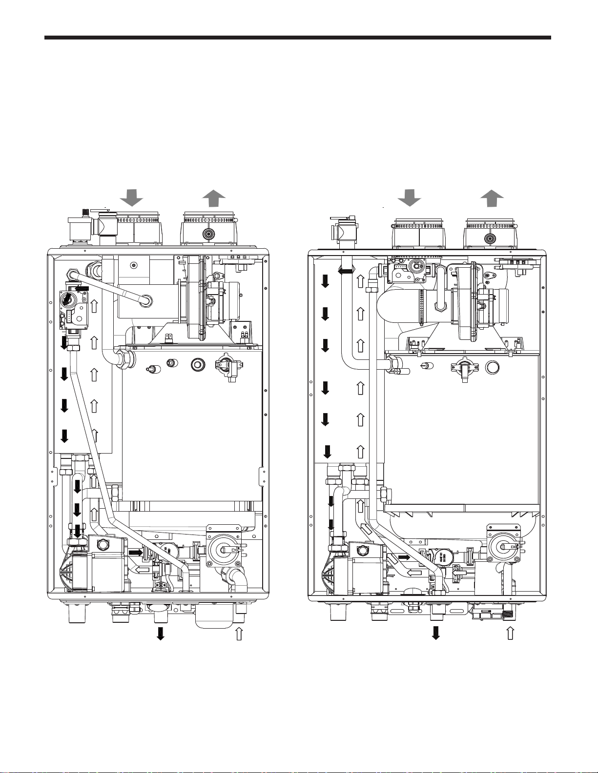
2.6 Product Flow Paths and Characteristics
2.6.1 Domestic Hot Water ow. Combination Boiler Domestic Hot Water Mode.
Cold water passes through the exchanger and is heated via a mini indirect tank.
The domestic hot water (DHW) is provided on demand.
Page 13
FTCW140
Combustion
Air
Vent
FTCW199
Combustion
Vent
Air
DHW Supply DHW Supply
DHW Return DHW Return
Page 14

Page 14
SECTION 3 Safety Regulations
3.1 Safety Symbols
WARNING
To avoid product damage, personal injury, or even
possible death, carefully read, understand, and
follow all the instructions in the Installation and
Operation manual before installation, operation
and service the Boiler.
Manufacturer cannot anticipate every
circumstance that might involve a potential
hazard. Therefore, all possible incidents are not
included in our warnings. Proper installation,
operation, and service are your responsibility.
You must make sure that the operation and
settings of the Boiler are safe for you and for
others.
This manual provides Safety Symbols. When the
user fails to adhere to the following requirement,
it may cause death, serious injury, and substantial
property damage.
For safety symbols, ‘DANGER’, ‘WARNING’,
CAUTION’ are indicated and the denitions for these
terms are as follow:
DANGER
Indicates an imminently hazardous situation which,
if not avoided, will result in death or serious injury.
This signal word is limited to the most extreme
situations.
WARNING
Indicates a potentially hazardous situation which, if
not avoided, could result in death or serious injury.
CAUTION
WARNING
FOR YOUR SAFETY READ BEFORE
OPERATING
If you do not follow these instructions exactly, a
re or explosion could result causing property
damage, personal injury or loss of life.
A. This appliance does not have a pilot. It
is equipped with an ignition device which
automatically lights the burner. Do not try to
light the burner by hand.
B. BEFORE OPERATING smell all around the
appliance area for gas. Be sure to smell next
to the oor because some gas is heavier than
air and will settle on the oor.
WHAT TO DO IF YOU SMELL GAS
• Do not try to light any appliance.
• Do not touch any electric switch; do not use any
phone in your building.
• Immediately call your gas supplier from a
neighbor’s phone. Follow the gas supplier’s
instructions.
• If you cannot reach your gas supplier, call the
re department.
C. Use only your hand to push in or turn the gas
control knob. Never use tools. If the knob will
not push in or turn by hand, don’t try to repair
it, call a qualied service technician. Force
or attempted repair may result in a re or
explosion.
D. Do not use this appliance if any part has
been under water. Immediately call a qualied
service technician to inspect the appliance and
to replace any part of the control system and
any gas control which has been under water.
Indicates a potentially hazardous situation which, if
not avoided, may result in minor or moderate injury.
It is also used to alert against unsafe practices and
hazards involving only property damage.
WARNING
Cancer and Reproductive Harm.
www.P65WARNINGS.CA.GOV.
as required by the state of California Proposition 65.
This appliance must be installed in accordance with
local codes if any; if not, follow ANSI Z224.1/NFPA
54 or CAN/CSA B149.1, Natural Gas and Propane
Installation Code, as applicable.
This appliance is certied for use at altitudes up
to 4,500ft(1,370m) in accordance to the latest CSA/
CGA 2.17-M91 Gas-Fired Appliances for Use at
High Altitudes.
Page 15
The FT Series Wall Mounted, Combination Boiler
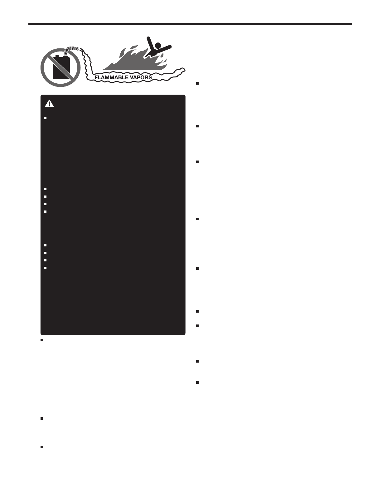
DANGER
Vapors from ammable liquids will explode and
catch on re. These will cause death or severe
burns.
Do not use or store ammable products such as
gasoline, solvents or adhesives in the same room
or area near the appliance.
Keep ammable products
Far away from boiler
In approved containers
Tightly closed
Out of children’s reach
Vapors
Cannot be seen
are heavier than air
spread on the oor
Can spread from other rooms to the main burner
by air currents
Do not install the appliance where ammable
products will be stored.
Read and follow boiler warnings and instructions
thoroughly. If owner’s manual is missing, contact
the retailer or manufacturer.
This combination boiler must be installed by a
qualied plumber, a licensed gas tter, and/or a
professional service technician.
Improper installation and/or operation will cause a
potentially hazardous situation, such as serious injury
or death. Also, it will void the warranty.
• The National Fuel Gas Code NFPA 54 / ANSI Z224.1
• National Electric Code ANSI/NEPA 70
• All applicable local, state, national and provincial
codes, regulations and laws.
Page 15
damaging condition that might aect the operation
of the unit. Boiler must be checked by a qualied
technician before resuming operation.
DO NOT use this Boiler if any part has been under
water. Immediately call a qualied technician for
inspecting the Boiler and replacing any part of the
control system and gas control which have been
under water.
Do not power up the unit until the gas and water
supply valves are fully opened. Make sure that the
fresh air intake port and exhaust gas port are opened
and functional.
DO NOT attempt to install, repair, or service this
Boiler by yourself.
Do not change any part of the Boiler.
Contact a qualied technician if the Boiler needs
repair or maintenance.
Ask your gas supplier for a list of qualied service
providers.
DO NOT use spray paint, hair spray, or any other
ammable spray near Boiler or near the exterior fresh
air inlet port. DO NOT place any items in or around
the exterior exhaust gas outlet port and/or fresh air
inlet port. These could restrict or block the ow in or
out of the vent system.
“Caution: While repairing control, all wires are
labeled. You must connect the wires in accordance
with the instruction.
Wiring errors can cause improper and dangerous
operation.
“Verify proper operation after servicing operation”
This consists of the gas ignition system components
which are protected from water (dripping, spraying, rain,
etc.) during operation and service (circulator replacement,
condensate trap, control replacement, etc.).
After installing the heater, safety devices must be
tested.
This boiler is equipped with a blocked vent shuto
system.
If the error code ‘41’ occurs, follow the instructions
below.
Proper care is your responsibility. Carefully read and
understand the Operating Information in this manual
before operating the Boiler.
Be aware of the location of the gas shut-o valve
and operation method. Close the gas shut-o valve
immediately if the appliance is subjected to re,
overheating, ood, physical damage, or any other
- First, turn o the manual gas valve.
- Make sure that there is no foreign object in the vent
passage or rodent screen.
- If you do not nd any problem, do the following.
- Turn o the error state by pressing the power button
of control panel.
- If the error occurs repeatedly, call your service
technician or gas supplier.
Page 16
Page 16
3.2 Safety Precautions and Proper Use
Before Operation
1. Check the Gas Type (NG/LP)
When using or moving the unit for the rst time, check
if gas type matches with the gas type of the Boiler.
Check whether the gas type which is supplied is NG
(Natural Gas) or LP (Propane) and also check the
Boiler gas type.
The gas type is indicated on the rating plate on side of
the Boiler.
2. Check the Power (120V 60Hz)
Check that the appliance is connected properly.
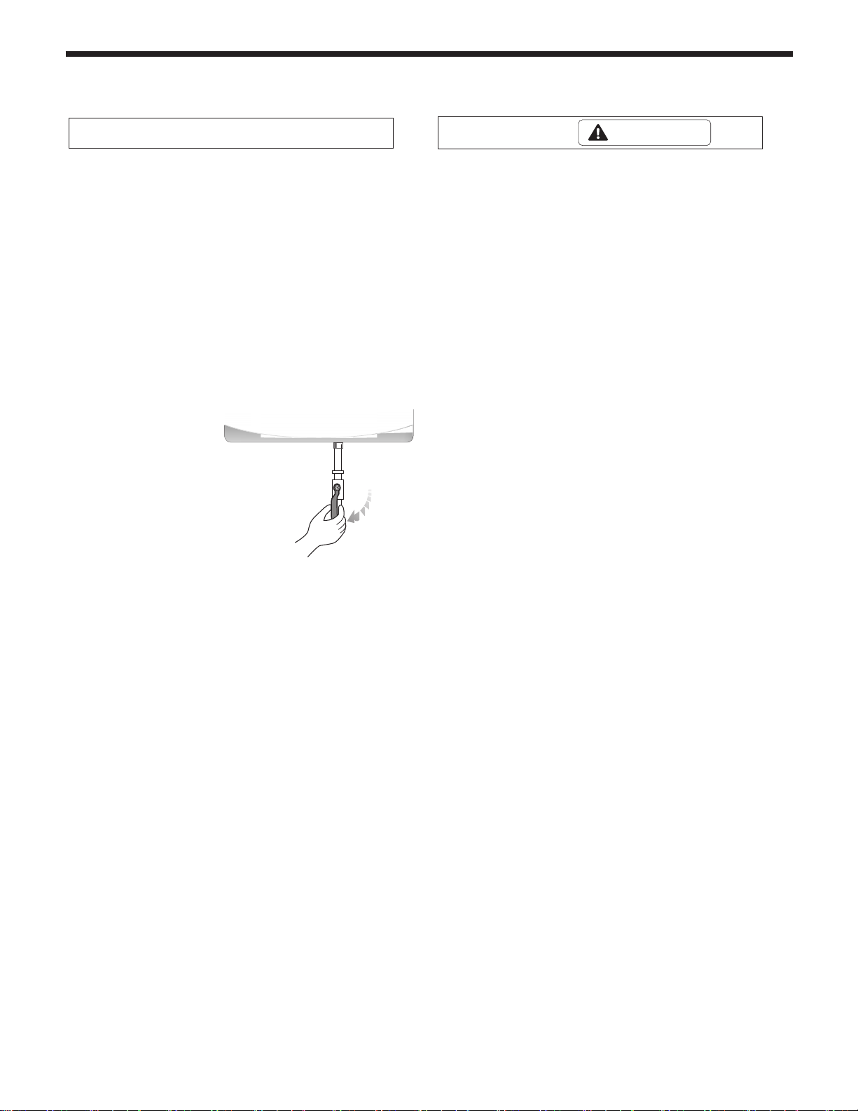
3. Check the Cold Water Inlet
valve
Please keep the
appliance water inlet
valve open at all times.
The appliance will not
ignite when insucient
water or no water is
in the heating pipes.
(valve: always open
position)
open
When in Operation
1. Caution for Gas leak
Frequently check for a gas leak at the gas connection
portion with soapy water.
Steps to take if you have a Gas leak.
1. Shut down the boiler as soon as gas fumes are
detected.
2. Close the intermediate gas valve.
3. Open windows for ventilation.
4. Call a qualied service technician for immediate
repair.
2. Caution for Ventilation
Make sure that there is sucient inow and outow of air
ventilation while using the unit.
If the ventilation is improper, combustion quality may
deteriorate inside the appliance and cause shortened life
of the appliance.
3. Burn Warning
Be careful not to burn yourself on the ue or pipes. They
become extremely hot during operation.
CAUTION
4. Check the Gas Valve
Check that the manual gas shut-o valve
that supplies the FT is opened.
5. Check the area around the appliance and remove
any combustible or ammable materials. Remove
laundry or any other items that are on or near the
boiler or vent pipe.
Page 17
The FT Series Wall Mounted, Combination Boiler
WARNING
Do not use the appliance for any other purpose
than for heating and hot water.
Do not store combustibles or ammable material such as
gasoline near the appliance.
Do not store other items on or near this boiler.
Do not store combustible (ammable) materials
such as papers.
Do not hang clothes on the vent pipe. This may
start a re.
CAUTION
Scalding Risk: Manufacturer
strongly recommends the
use of an anti-scald mixing
valve at domestic hot water
outlet (boiler location) to
reduce potential for scalding.
Contact Manufacturer for
recommended models.
Check with local codes.
__________________________________________
Page 17
After repair of gas pipeline or gas regulator
replacement, call A qualied contractor for inspection
before starting it up.
Carbon monoxide poisoning
If vent pipe fumes enter the room, it could cause
poisoning by carbon monoxide gas. Check that the
vent pipes are properly connected. Open windows
for ventilation. Call a qualied service technician for
immediate repair.
Gas leakage test.
Gas supply line must be inspected regularly.
Do not shut o the Boiler.
When you leave home for a long time, do not shut o
Boiler. The Boiler has a freeze protection function. The
ceramic heater is installed inside of the heater’s internal
pipe to protect the heater from freezing.
Do not wipe the appliance or control panel with wet
cloth. Electric shock may occur, or internal parts may
fail due to the exposure to moisture.
Do not disassemble the Boiler.
If repair is required, call your local qualied technician.
Page 18

Page 18
18
46
3
8
3
8
24
61
12
30
SECTION 4 Installation
4.1 Location and Clearances
The FT must be mounted to a suitable wall by a
qualied heating contractor under the guidelines of a
boiler. The wall may be of concrete or wood. Suitable
fasteners for concrete or wood must be used. Failure to
wall mount this boiler using correct fasteners will aect
the performance and life expectancy of the boiler and
will void the warranty.
WARNING
Installations must comply with
• All the local, state, provincial, and national codes,
laws, regulations and ordinances.
• National Fuel Gas Code, ANSI Z223.1 – The latest
version.
• National Electrical Code.
• A National Standard of Canada CAN/CSA-B149.1
Check before placing the Combination boiler
• Always check the connected components which are
near to the heater. The components are below.
Water piping position / Venting adapter / Gas supply
piping / Electrical power / Condensate drain hose.
• Inspect area around Combination boiler. Remove
any combustible materials, gasoline and other
ammable liquids. Failure to keep Combination
boiler area clear and free of combustible materials,
gasoline and other ammable liquids and vapors can
result in severe personal injury, death or substantial
property damage.
• The Combination boiler which has gas control
system components must be protected from any
possible danger during operation and service.
• If new Combination boiler replaces an existing
appliance, check and correct system problems, for
example:
- Do not install if: System leaks causing oxygen
corrosion or heat exchanger cracks from hard water
deposits.
Provide clearances
• If the heater was installed in a narrow space
or corner, please ensure that there is sucient
space for service and maintenance access. For
regular maintenance, gas and water lines must be
accessible.
Minimum clearances to Combustibles.
For Installation from
Non-Combustibles and
Combustibles
TOP of appliance
BACK of appliance
FRONT of
appliance
SIDE of appliance
BOTTOM of
appliance
Table 1. Minimum Clearances
to Combustibles and for Service.
18 in
(46 cm)
5
/
in
8
(1.5 cm)
24 in
(61 cm)
3 in
(7 cm)
12 in
(30 cm)
Suggested
Service
Clearance
18 in
(46 cm)
5
/
in
8
(1.5 cm)
40 in
(101 cm)
8 in
(20 cm)
24 in
(61 cm)
The boiler must be installed on a wall that can bear its weight.
WARNING
CLEARANCES FOR SERVICE ACCESS
• If you do not provide the minimum clearances
shown, it might not be possible to service the
boiler without removing it from the space.
• Space must be provided with combustion /
ventilation air openings correctly sized for
all other appliances located in the same
space as the boiler. The boiler cover must be
securely fastened to prevent it from drawing
air from the boiler room. This is particularly
important if the boiler is in a room with other
appliances. Failure to comply with the above
warnings could result in substantial property
damage, severe personal injury, or death.
Page 19
The FT Series Wall Mounted, Combination Boiler
Page 19
4.2 Wall Mount Bracket
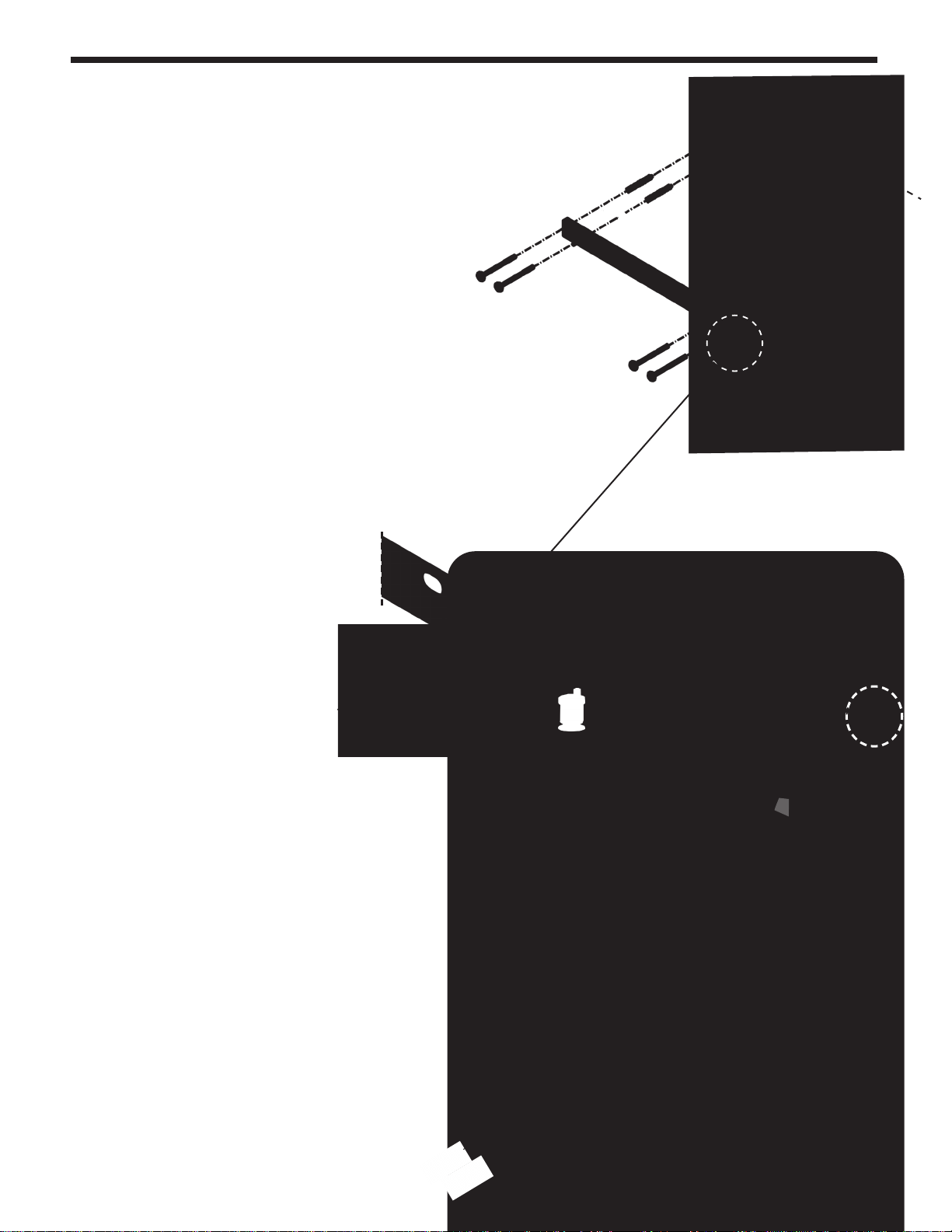
• The installation height and location for your
FT depends on your installation scenario. With all clearances
considered, and given adequate positioning for air supply
and venting, you will need to determine the best position
to mount the Wall Mount Bracket. The wall must be
concrete, wood, or plywood over studs, and must be
strong enough to hold the boiler!
• Start by familiarizing yourself to how the
included Wall Mount Bracket hooks underneath
the two Hangers that are attached to the back of
the boiler. The ‘hooks’ of the Wall Mount Bracket will
be 3” from the Top of the boiler once the boiler is hung.
• Position the Wall Mount Bracket at the location that it will go,
being sure that it is level, and then drill 4 holes (0.47”dia)
with a 1/2” drill bit, into the wall through the Bracket.
• If mounting to a concrete wall, then use the concrete anchors.
If onto wood or 5/8” (16 mm) plywood, then use the wood
screws. Do not hang the FT onto sheetrock unless it is
possible to fasten directly into
the structural studs. If the
included anchors do not suit
your installation, you must use
‘Field Supplied’ anchors that
are appropriate for the wall’s
construction.
Bolts (4)
Anchors
(4)
Wall Mount
Bracket
3" to Top
of Unit
*
Concrete,
Wood,
or 5/8" Plywood
Wall Mount
Bracket
Hangers (2)
(fastened to the back of unit)
Hang the Boiler
• Lift the boiler up, align the Hangers on the back
of the boiler with the hooks on the Wall Mount
Bracket, and hang the boiler onto the Wall Mount
Bracket. Do a visual inspection to make sure that
the boiler is hanging properly onto the hooks of
the Wall Mount Bracket.
• Fasten the bottom of the boiler to the wall using
2 suitable wall anchors (eld supplied).
Page 20

Page 20
4.3 Combustion Air
FT boilers must have provisions for combustion
and ventilation air in accordance with the applicable
requirements for Combustion Air Supply and Ventilation
in the National Fuel Gas Code, ANSI Z223 1; or in
Canada, the Natural Gas and Propane Installation Code,
CSA B149.1. All applicable provisions of local building
codes must also be adhered to.
A FT unit can take combustion air from the space
in which it is installed, or the combustion air can be
ducted directly to the unit. Ventilation air must be
provided in either case.
4.3.1 Combustion Air from Room
In the United States, the most common requirements
specify that the space shall communicate with the
outdoors in accordance with method 1 or 2, which follow.
Where ducts are used, they shall be of the same cross-
sectional area as the free area of the openings to which
they connect.
Method 1: Two permanent openings, one commencing
within 12” (300mm) of the top and one commencing
within 12” (300mm) of the bottom, of the enclosure
shall be provided. The openings shall communicate
directly, or by ducts, with the outdoors or spaces
that freely communicate with the outdoors. When
directly communicating with the outdoors, or when
communicating to the outdoors through vertical ducts,
each opening shall have a minimum free area of 1
square inch per 4000 Btu/hr (550 square mm/kW) of
total input rating of all equipment in the enclosure. When
communicating to the outdoors through horizontal ducts,
each opening shall have a minimum free area of not
less than 1 square inch per 2000 Btu/hr (1100 square
mm/kW) of total input rating of all equipment in the
enclosure.
Method 2: One permanent opening, commencing
within 12” (300mm) of the top of the enclosure, shall
be permitted. The opening shall directly communicate
with the outdoors or shall communicate through a
vertical or horizontal duct to the outdoors or spaces
that directly communicate with the outdoors and shall
have a minimum free area of 1 square inch per 3000
Btu/hr (734 square mm/kW) of the total input rating of
all equipment located in the enclosure. This opening
must not be less than the sum of the areas of all vent
connectors in the conned space.
Other methods of introducing combustion and
ventilation air are acceptable, providing they conform to
the requirements in the applicable codes listed above.
In Canada, consult local building and safety codes or, in
absence of such requirements, follow CAN/CGA B149.1
4.3.2 Ducted Combustion Air
The combustion air can be taken through the wall, or
through the roof. When taken from the wall, it must be
taken from out-of-doors by means of the horizontal wall
terminal. When taken from the roof, a eld-supplied rain
cap or an elbow arrangement must be used to prevent
entry of rain water.
Use ABS, PVC, CPVC, polypropylene, or galvanized
pipe for the combustion air intake. Route the intake
to the boiler as directly as possible. Seal all joints.
Provide adequate hangers. The unit must not support
the weight of the combustion air intake pipe. Maximum
linear pipe length allowed is shown in Table 5. Subtract
5 allowable linear ft. (1.5m) for every elbow used.
The connection for the intake air pipe is at the top of
the unit.
In addition to air needed for combustion, air shall also
be supplied for ventilation, including air required for
comfort and proper working conditions for personnel.
COMBUSTION AIR INSTALLATION STANDARDS
MATERIAL UNITED STATES CANADA
ABS ANSI/ASTM D1527
PVC, sch 40 ANSI/ASTM D1785 or D2665 Air pipe material must be chosen
CPVC, sch 40 ANSI/ASTM F441 CPVC, sch 40, ANSI/ASTM, Polypropylene
Polypropylene UL1738, ULC S636. based upon the intended application of the boiler.
Single wall galv. steel 26 gauge
Table 2. Required Combustion Air Pipe Material.
Page 21
The FT Series Wall Mounted, Combination Boiler
Page 21
The instructions for the installation of the venting
system shall specify that the horizontal portions of
the venting system shall be supported to prevent
sagging; the methods of and intervals for support
shall be specied. These instructions shall also
specify that the venting system:
Category I, II and IV boilers must be installed so
that horizontal sections have a slope of at least ¼
inch per foot (21 mm/m) to prevent accumulation of
condensate; and
For Category II and IV boilers, where necessary,
have means provided for drainage of condensate.
CAUTION
The FT is standard as a Natural Gas Boiler and
must be converted if propane is the desired gas, unless
specically manufactured for propane.
Adequate drainage
• The appliance should be installed not to damage
the adjacent area. If such locations cannot be
avoided, it is recommended that a suitable drain
pan, adequately drained, be installed under the
appliance. The pan must not block combustion air
ow.
NOTICE
Les instructions d'installation du système
d'évacuation doivent préciser que les sections
horizontales doivent être supportées pour prévenir
le échissement. Les méthodes et les intervalles
de support doivent être spéciés. Les instructions
doivent aussi indiquer les renseignements suivants:
les chaudières de catégories I, II et IV doivent
présenter des tronçons horizontaux dont la pente
montante est d'au moins ¼ po par pied (21 mm/m)
entre la chaudière et l'évent; les chaudières de
catégories II et IV doivent être installées de façon à
empêcher l'accumulation de condensat;
et si nécessaire, les chaudières de catégories II et IV
doivent être pourvues de dispositifs d'évacuation du
condensat.
AVIS
Connecting the Water Supply
• To conserve water and energy, insulate all water
piping—especially the hot and recirculation water
lines. Never cover the drain or pressure relief valve.
Having a backow preventer in the cold water
supply line will prevent thermal expansion
backow. Contact the water supplier or local
plumbing inspector for information about how to
control this situation.
If overheating occurs or the gas supply fails to shut
o, turn o the manual gas valve.
This installation must conform with below section
• “Air for Combustion and Ventilation” of the
National Fuel Gas Code, ANSI Z224.1/NFPA 54,
or Sections 8.2, 8.3 or 8.4 of Natural Gas and
Propane Installation Code, CAN/CSA B149.1, or
applicable provisions of the local building codes.
Page 22
Page 22
4.4 Venting (Exhaust)
DO NOT COMMON VENT FT UNITS. FT
units are never permitted to share a vent with
Category I appliances.
NOTICE
WARNING
All venting must be installed according to this manual
and any other applicable local codes, including but
not limited to, ANSI Z224.1/NFPA 54, CAN/CSA
B149.1 and ULC-S636. Failure to follow this manual
and applicable codes may lead to property damage,
severe injury, or death.
NE PAS ÉVENT COMMUNE FT UNITÉS. FT
unités ne sont jamais autorisés à partager un
évent Catégorie I avec les appareils.
The ue temperature of the FT changes
dramatically with changes in operating water
temperature. Therefore, it is necessary to assess
the application of the boiler to determine the
required certied vent class. If the FT is installed
in an application where the ambient temperature
is elevated, and/or installed in a closet/alcove,
CPVC, polypropylene, or stainless steel material is
required. If the system temperatures are unknown
at the time of installation, stainless, polypropylene
or CPVC material is recommended.
The FT is a Category IV appliance and may be
installed with PVC, CPVC or polypropylene that
complies with ULC-S636, ANSI/ASTM D1785 F441
(see Table 3) or a stainless steel venting system that
complies with UL 1738 Standard and ULC S636.
Failure to use the appropriate vent material,
installation techniques, glues/sealants could lead to
vent failure causing property damage, personal injury
or death.
AVIS
WARNING
Use of cellular core PVC (ASTM F891), cellular core
CPVC, or Radel® (polyphenolsulfone) in non-metallic
venting systems is prohibited and covering non-
metallic vent pipe and ttings with thermal insulation is
prohibited.
INSTALLATIONS IN CANADA require the use
of venting material certied to ULCS636. All Gas
vents connected to the FT, plastic, stainless steel
or otherwise must be certied to this ULC stand-
ard. Appropriate selection of vent material is very
important for proper performance and safe opera-
tion of the FT.
The ue temperature of the FT changes dramati-
cally with changes in operating water temperature.
Therefore, it is necessary to assess the application
of the boiler to determine the required certied vent
class. If the FT is installed in an application where
the outlet water temperature exceeds 145°F, and/or
installed in a closet, class IIB or higher vent material is required. If the system temperatures are un-
known at the time of installation, class IIB or higher
venting material is recommended.
IN CANADA all venting used must meet the
following requirements:
1. ULC-S636 certied and marked
2. The rst 3 feet of venting must be accessible
for visual inspection.
3. All components used in the vent system must
be from a certied manufacturer.
WARNING
VENTING INSTALLATION STANDARDS
MATERIAL UNITED STATES CANADA
Stainless Steel UL 1738 Venting must be ULC-S636 certied for use as
PVC, sch 40 ANSI/ASTM D1785 venting material. The venting material must be chosen
CPVC, sch 40 ANSI/ASTM F441 based upon the intended application of the boiler.
Polypropylene UL1738 or ULC-S636
Table 3. Required Exhaust Vent Material.
Page 23

The FT Series Wall Mounted, Combination Boiler
Page 23
4 . Vent system components must not be mixed
with alternate manufacturers certied
components and/or unlisted components.
5 . The venting must be installed according
to the vent manufacturers installation
instructions.
The unit’s vent can terminate through the roof, or
through an outside wall.
Vent pipe must pitch upward, toward the vent
terminal, not less than 1/4” per foot, so that
condensate will run back to the FT to drain. Route
vent pipe to the heater as directly as possible. Seal
all joints and provide adequate hangers as required
in the venting system manufacturer’s Installation
Instructions. Horizontal portions of the venting
system must be supported to prevent sagging and
may not have any low sections that could trap
condensate. The unit must not support the weight of
the vent pipe.
WARNING
Failure to vent this Boiler in accordance with these
instructions could cause a re, resulting in severe
property damage, personal injury or death.
Do not interchange vent systems or materials unless
it is specied.
The use of thermal insulation covering pipe and
ttings is prohibited.
Do not apply an electric damper, draft hood or vent
damper with this Boiler.
Do not locate vent termination where exposed
to prevailing winds. Moisture and ice may fall
on surface around vent termination. To prevent
deterioration, surface must be in good repair
(sealed, painted, etc.).
4.5 General Location Guideline
1. Vent system installation must be in accordance
with Local codes or, in the absence of local codes,
the National Fuel Gas Code, ANSI Z224.1 /NFPA
54 and/or CSA B149.1, Natural Gas and Propane
Installation Code.
2. The Boiler is designed to be installed as a Direct
Vent (sealed combustion) type. The air for
combustion must be supplied directly from the
outside to the burner. Also, the ue gases must be
vented directly to the outdoors (through wall or roof).
3. Do not install venting system components on the
exterior of building except as specically required by
these instructions
- Vent terminals must be at least 1 foot from any door,
window, or gravity inlet into the building.
- Maintain the correct clearance and orientation
between the vent and air intake terminals.
The vent and air intake terminals must be at the
same height and their center lines must be spaced
apart 12˝ minimum.
- The bottom of the vent and air intake terminal must
be at least 12˝ above the normal snow line. In no
case should they be less than 12˝ above grade
level.
- Do not install the vent terminal directly over
windows or doors.
- Air intake terminal must not terminate in areas that
might contain combustion air contaminates, such
as near swimming pools.
- For sidewall venting, the minimum horizontal
distance between any adjacent individual Module
(Boiler) vent terminations is twelve (12) inches. It
is better to be far more than 12 inches for avoiding
frost damage to building surfaces where vent
terminations are placed.
- The minimum horizontal distance between any
adjacent individual module (boiler) roof vent
endpiece is one (1) foot.
Page 24
Page 24
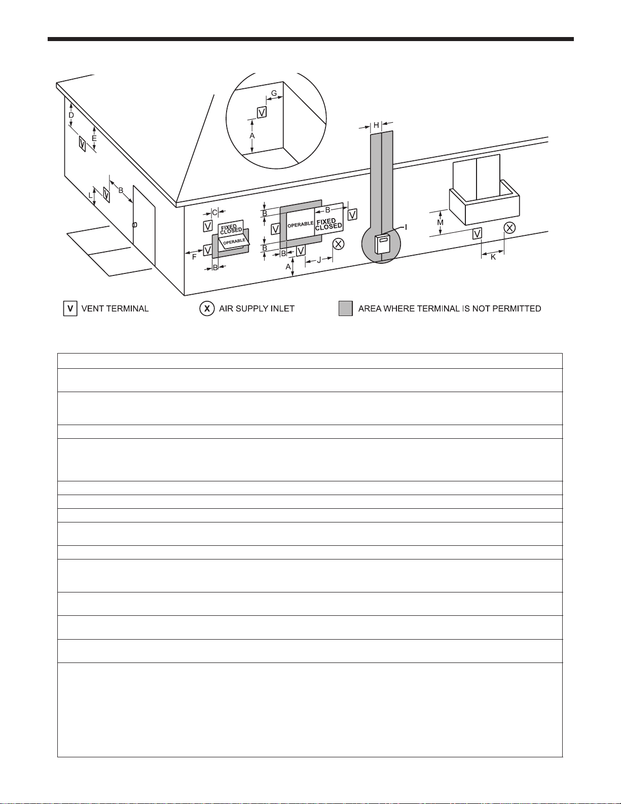
4.6 Locations for Vent Pipe Terminator
4.6.1 Direct Venting Clearances
U.S. Installations (see note 1) Canadian Installations (see note 2)
A= Clearance above grade, veranda, porch, 12 inches (30 cm) 12 inches (30 cm)
deck, or balcony See note 6 See note 6
B= Clearance to window or door that may be Direct vent only: 12 inches (30cm); 36 inches (91 cm)
opened Other than Direct vent: 4 ft (1.2m) below or to NT 80 only - 12 inches (30 cm)
side of opening; 1 ft (30cm) above opening
C= Clearance to permanently closed window See note 4 See note 5
D= Vertical clearance to ventilated sot located
above the terminal within a horizontal See note 4 See note 5
distance of 2 feet (61cm) from the center
line of the terminal
E= Clearance to unventilated sot See note 4 See note 5
F= Clearance to outside corner See note 4 See note 5
G= Clearance to inside corner See note 4 See note 5
H= Clearance to each side of center line 3 feet (91 cm) within a height 15 feet
extended above meter/regulator assembly See note 4 above the meter/regulator assembly
I= Clearance to service regulator vent outlet See note 4 3 feet (91 cm)
J= Clearance to nonmechanical air supply Direct vent only: 12” (30cm) 80-285; 36” (91cm)
inlet to building or the combustion air inlet 399-850. Other than Direct vent: 4 ft (1.2m) below 36 inches (91 cm)
to any other appliance or to side of opening; 1 ft (30cm) above opening NT 80 only - 12 inches (30 cm)
K= Clearance to a mechanical air supply inlet 3 feet (91 cm) above if within 10 feet (3 m) 6 feet (1.83 m)
horizontally
L= Clearance above paved sidewalk or paved Vent termination not allowed in this location 7 ft (2.1 m)
driveway located on public property for category IV appliances. See note 5
M= Clearance under veranda, porch, deck, See note 4 12 inches (30 cm) (see note 3)
or balcony
Notes:
1. In accordance with the current ANSI Z223.1 / NFPA 54 National Fuel Gas Code.
2. In accordance with the current CAN/CSA-B149.1 Installation Codes.
3. Permitted only if veranda, porch, deck, or balcony is fully open on a minimum of two sides beneath the oor.
4. For clearances not specied in ANSI Z223.1 / NFPA 54, clearance is in accordance with local installation codes and the requirements of the gas supplier.
5. For clearances not specied in CAN/CSA-B149, clearance is in accordance with local installation codes and the requirements of the gas supplier.
6. IMPORTANT: Terminal must be placed such that it remains a minimum 12” above expected snow line. Local codes may have more
specic requirements, and must be consulted.
Table 4. Direct Vent Clearances
Page 25

The FT Series Wall Mounted, Combination Boiler
4.6.2 Venting Requirements in the
Commonwealth of Massachusetts
Page 25
In Massachusetts the following items are required if
the side-wall exhaust vent termination is less than
seven (7) feet above nished grade in the area
of the venting, including but not limited to decks
and porches. From Massachusetts Rules and
regulations 248 CMR 5.08
1. Installation of Carbon Monoxide Detectors
At the time of installation of the side wall
vented gas fueled appliance, the installing plumber
or gastter shall observe that a hard-wired carbon
monoxide detector with an alarm battery back-up is
installed on the oor level where the gas appliance
is to be installed. In addition, the installing plumber
or gastter shall observe that a battery operated or
hard-wired carbon monoxide detector with an alarm
is installed on each additional level of the dwelling,
building or structure served by the side-wall
horizontally vented gas fueled equipment. It shall
be the responsibility of the property owner to secure
the services of qualied licensed professionals
for installation of hard-wired carbon monoxide
detectors.
a. In the event that the side-wall horizontally
vented gas fueled equipment is installed in a crawl
space or an attic, the hard-wired carbon monoxide
with alarm and battery back-up may be installed on
the next adjacent oor level.
b. In the event that the requirements of the
subdivision cannot be met at the time of completion
of installation, the owner shall have a period of thirty
(30) days to comply with the above requirements,
provided, however, that during said thirty (30) day
period, a battery operated carbon monoxide detector
with an alarm be installed.
2. Approved Carbon Monoxide Detectors
Each carbon monoxide detector shall comply
with NFPA 720 and be ANSI/UL 2034 listed and IAS
certied.
3. Signage. A metal or plastic identication plate
shall be permanently mounted to the exterior of
the building at a minimum height of eight (8) feet
above grade directly in line with the exhaust vent
terminal for horizontally vented gas fueled heating
appliance or equipment. The sign shall read, in
print no less than one-half (1/2) inch in size: “GAS
VENT DIRECTLY BELOW, KEEP CLEAR OF ALL
OBSTRUCTIONS”.
4. Inspection The state or local gas inspector of
the side-wall horizontally vented gas fueled appliance
shall not approve the installation unless, upon
inspection, the inspector observes carbon monoxide
detectors and signage installed in accordance with the
provisions of 248 CMR 5.08(2)(a) 1-4.
Page 26
Page 26
4.7 Common Vent Test
NOTE: This section does not describe a method for
common venting FT units. It describes what must
be done when an existing unit is removed from a
common vent system.
At the time of removal of an existing boiler, the following steps
shall be followed with each appliance remaining connected to
the common venting system placed in operation, while the other
appliances remaining connected to the common venting system
are not in operation.
1. Seal any Not Used openings in the common venting system.
2. Visually inspect the venting system for proper size and
horizontal pitch and determine there is no blockage or
restriction, leakage, corrosion and other deciencies which
could cause an unsafe condition.
3. Insofar as is practical, close all building doors and windows
and all doors between the space in which the appliances
remaining connected to the common venting system are
located and other spaces of the building. Turn on clothes
dryers and any appliance not connected to the common
venting system. Turn on any exhaust fans, such as range
hoods and bathroom exhausts, so they will operate at
maximum speed.
4. Place in operation the appliance being inspected. Follow the
lighting instructions. Adjust thermostat so the appliance will
operate continuously.
5. Operate the main burner for 5 minutes then, determine if the
cut-draw overows to the discharge opening. Use the ame
of a match or a candle or the smoke of a cigarette, a cigar or
a pipe
6. Once it has been determined, according to the method
indicated above, that each device connected to the drainage
system is placed in the open air in an adequate manner.
Install the doors and windows, fans, the registers of chimneys
and gas appliances to their original position
7. Any malfunction of the venting system should be corrected so
that the installation conforms to the National Fuel Gas Code,
ANSI Z223.1/NFPA 54 and (or) the installation codes CAN/
CSA-B149.1. If the size of a section of the evacuation system
must be changed, the system should be modied to comply
with the minimum values of the relevant tables of appendix F
of the National Fuel Gas Code, ANSI Z223.1/NFPA 54 and
(or) the installation codes CAN/CSA-B149.1
NOTICE
Au moment du retrait d'une chaudière existante, les mesures
suivantes doivent être prises pour chaque appareil toujours raccordé
au système d'évacuation commun et qui fonctionne alors que
d'autres appareils toujours raccordés au système d'évacuation ne
fonctionnent pas:
1. Sceller toutes les ouvertures non utilisées du système
d'évacuation.
2. Inspecter de façon visuelle le système d'évacuation pour
déterminer la grosseur et l'inclinaison horizontale qui conviennent
et s'assurer que le système est exempt d'obstruction,
d'étranglement, de fuite, de corrosion et autres défaillances qui
pourraient présenter des risques.
3. Dans la mesure du possible, fermer toutes les portes et les
fenêtres du bâtiment et toutes les portes entre l'espace où les
appareils toujours raccordés au système d'évacuation sont
installés et les autres espaces du bâtiment. Mettre en marche
les sécheuses, tous les appareils non raccordés au système
d'évacuation commun et tous les ventilateurs d'extraction comme
les hottes de cuisinière et les ventilateurs des salles de bain.
S'assurer que ces ventilateurs fonctionnent à la vitesse maximale.
Ne pas faire fonctionner les ventilateurs d'été. Fermer les registres
des cheminées.
4. Mettre l'appareil inspecté en marche. Suivre les instructions
d'allumage. Régler le thermostat de façon que l'appareil fonctionne
de façon continue.
5. Faire fonctionner le brûleur principal pendant 5 min ensuite,
déterminer si le coupe-tirage déborde à l'ouverture de décharge.
Utiliser la amme d'une allumette ou d'une chandelle ou la fumée
d'une cigarette, d'un cigare ou d'une pipe.
6. Une fois qu'il a été déterminé, selon la méthode indiquée ci-
dessus, que chaque appareil raccordé au système d'évacuation
est mis à l'air libre de façon adéquate. Remettre les portes et
les fenêtres, les ventilateurs, les registres de cheminées et les
appareils au gaz à leur position originale.
7. Tout mauvais fonctionnement du système d'évacuation commun
devrait être corrigé de façon que l'installation soit conforme au
National Fuel Gas Code, ANSI Z223.1/NFPA 54 et (ou) aux codes
d'installation CAN/CSA-B149.1. Si la grosseur d'une section
du système d'évacuation doit être modiée, le système devrait
être modié pour respecter les valeurs minimales des tableaux
pertinents de l'appendice F du National Fuel Gas Code, ANSI
Z223.1/NFPA 54 et (ou) les codes d'installation CAN/CSA-B149.1
AVIS
NOTICE
DO NOT COMMON VENT FT UNITS. FT units
are never permitted to share a vent with
Category I appliances.
AVIS
NE PAS ÉVENT COMMUNE FT UNITÉS. FT unités
ne sont jamais autorisés à partager un évent
Catégorie I avec les appareils.
Page 27
The FT Series Wall Mounted, Combination Boiler
4.8 Air Supply and Vent Connections
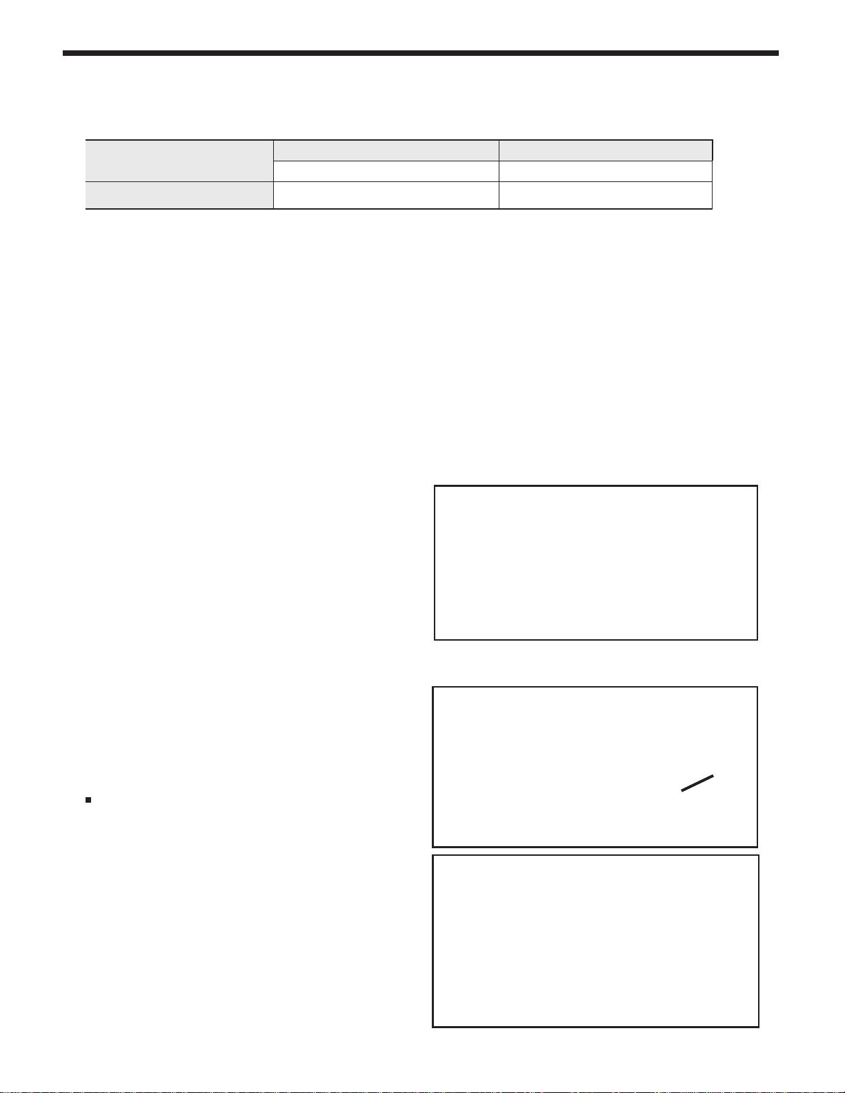
4.8.1 Vent / Air Pipe Lengths
Page 27
Combination Boiler Model
FTCW140/199 100´ (30M)
Table 5. Maximum Vent / Air Pipe Lengths for either 3” or 2 “ Pipes
Propane models are limited to 25 equivalent feet of 2” vent
*
NOTE : For each elbow, reduce maximum allowable length
• 5 feet (1.5M) for each 3-inch 90-degree elbow
• 2.5 feet (0.75M) for each 3-inch 45-degree elbow
• 8 feet (2.4M) for each 2-inch 90-degree elbow
• 4 feet (1.2M) for each 2-inch 45-degree elbow
• Maximum of 6 elbows for 3” vent. Max of 4 elbows for 2” vent.
NOTE: When using a 2” vent pipe, DIP Switch 4 must be in the OFF position.
For 3” Pipe vent, the default setting for DIP 4 is ON.
Refer to Section 4.19
4.7.2 Direct Venting
The boiler uses 3˝ or 2˝ diameter exhaust and 3˝
or 2˝diameter intake air ducts. To ensure the draw
of air directly from and exhaust of air directly to the
outside of the building, create an airtight seal from
the boiler collar to the vent termination.
3˝ Combustion Air / Vent Pipe 2˝ Combustion Air / Vent Pipe
Max Max
50´
(15M*)
*
3” pipe
(For installations in Canada) eld-supplied plastic
vent piping must comply with CAN/CSA B149.1
(latest edition) and be certied by the Standard
For Type BH Gas Venting Systems, ULC-S636.
Components of this listed system must not be
interchanged with other vent systems or unlisted
pipes or ttings. All plastic components and
specied primers and glues of the certied vent
system must be from a single system manufacturer
and must not be intermixed with another system
manufacturer’s parts.
Tightening — Boiler Collar (Socket) to Vent
Pipe & Inlet Pipe
- Clean and dry your selected PVC, CPVC vent
pipe and boiler collar (socket).
- You can select to the size of vent pipe(2˝ & 3˝),
according to the installation conditions.
- Push the pipe into the collar (socket) until it
touches the bottom of the socket tting.
- For 2” installations, install a eld supplied 3” to
2” adaptor. Adaptor must be installed in vertical
section of piping only.
2” pipe connected, using an adapter
3” to 2”
adapter
is NOT
included.
Page 28
Page 28
4.8.2 Indoor Combustion Air
Read and Follow Sections 4.3 Guidelines First.
1. Insert the termination end cap into the intake air duct.
2. Provide two openings to allow for circulation of
combustion air as specied by ANSI Z224.1/NFPA 54.
In Canada refer to CAN/CSA B-149.1
NOTE: The FT needs fresh air for safe operation and
must be installed so there are provisions for
adequate combustion and ventilation air.
Model FTCW140 FTCW199
Maximum Input (BTU/H) 140,000 199,000
Indoor make up air is provided, a mini-
mum free area of 1 in 2 per 1,000 BTU/H
4.9 Vent / Air Pipe Termination
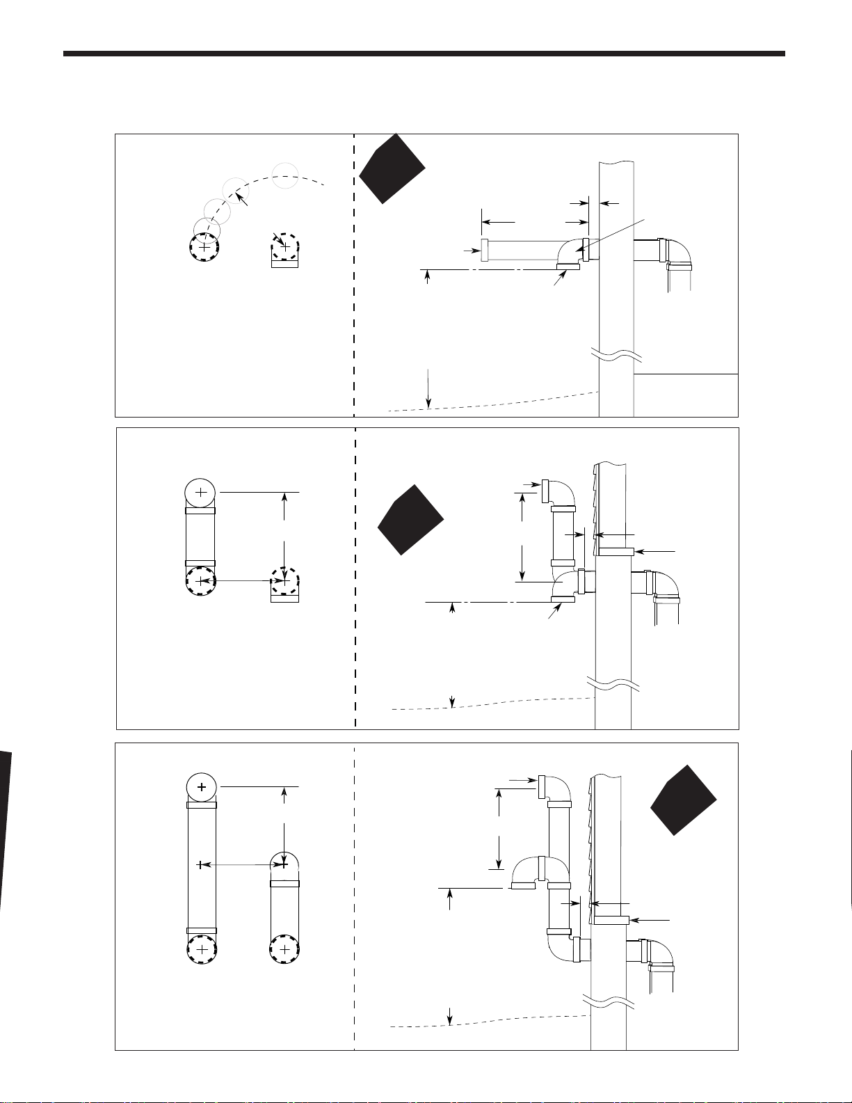
Vent Air Terminations:
After connecting terminals install vent screens on
both the vent and air inlet.
Two 3” vent screens are included with each unit.
Additional replacement screens are available for
purchase.
2” Vent Screen P/N - FT1508
3” Vent Screen P/N - FT1730
140 in2 13 1/4"
(W) x 13 1/4" (H)
199 in2 13 1/4"
(W) x 13 1/4" (H)
Vertical Vent Termination
• Direct Vent - Vertical Terminations
with Sloped Roof
Vent Screens
are required
Page 29
The FT Series Wall Mounted, Combination Boiler
SIDE VIEW
FRONT VIEW
Exhaust Screen
12” MIN
1” MIN
Exhaust
Combustion
Intake
Air Intake Screen
Exterior Wall
NOTE: Must be 12”
Minimum distance
above highest
anticipated snow level
or grade, whichever is
greater (TYP).
NOTE: The Exhaust must
be equal to or above the
Combustion Intake while at
a Minimum of 12” apart.
12” MIN
Apart
Exhaust
90o Elbow
Exhaust
Screen
Exhaust
Exhaust
12” MIN
1” MIN
Sill
Combustion
Intake
Combustion
Intake
SIDE VIEWFRONT VIEW
Exterior Wall
NOTE: Must be 12”
Minimum distance
above highest
anticipated snow level
or grade, whichever is
greater (TYP).
12” MIN
12”
MIN
Exhaust Screen
Exhaust
12” MIN
12” MIN
1” MIN
Sill
Combustion
Intake
Combustion
Intake
SIDE VIEWFRONT VIEW
Air Intake Screen
90o Elbow
Exterior Wall
12”
NOTE: Must be 12”
Minimum distance
above highest
anticipated snow level
or grade, whichever is
greater (TYP).
Exhaust
MIN
Page 29
Horizontal Vent Termination
• Direct Vent - Sidewall Termination
A
4.8 Vent / Air Pipe Termination (continued)
Vent Screens are required
B
C
Vent Screens
are required
Vent
Screens are
required
Page 30
Page 30
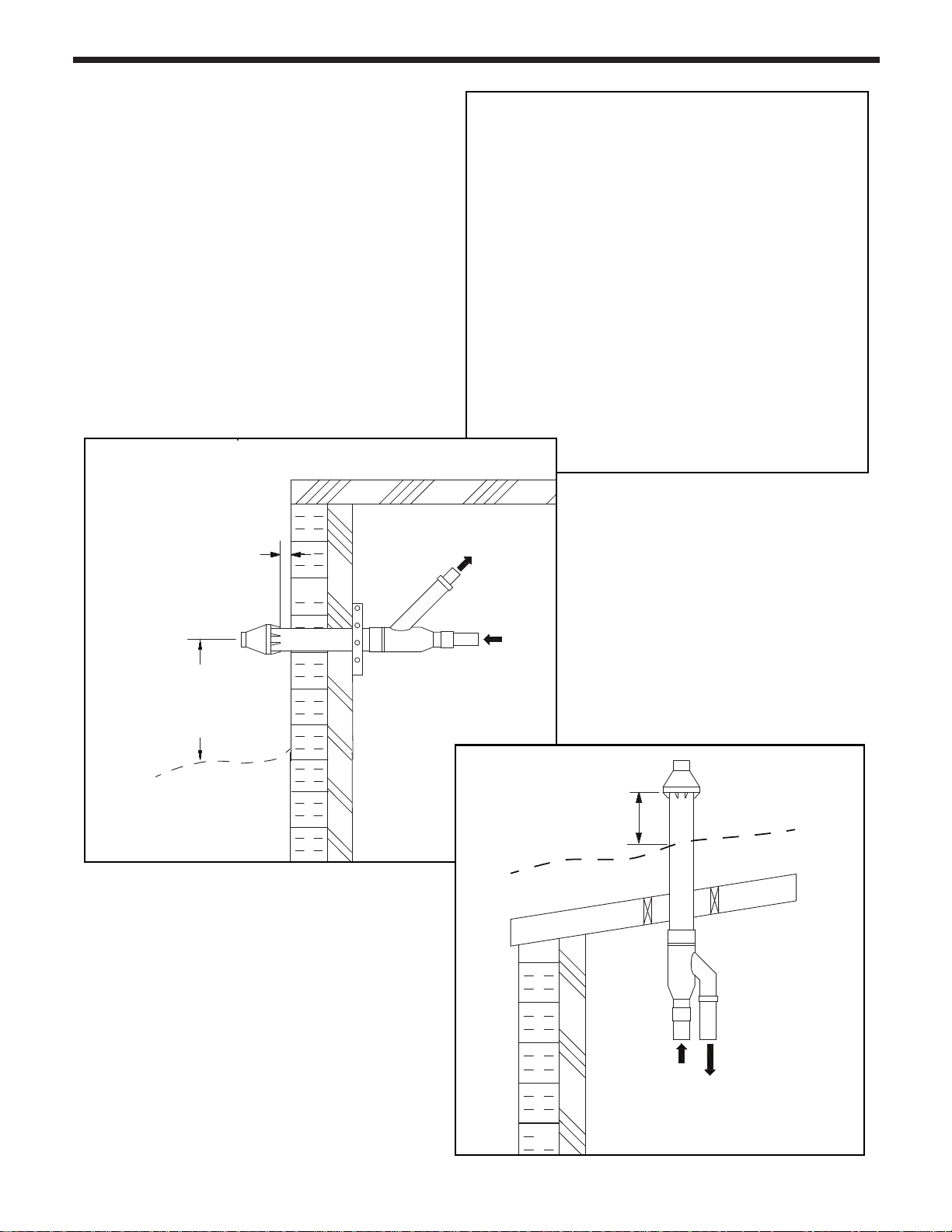
• Direct Vent - Optional Side wall Terminations
4. Concentric Vent Termination
• Direct Vent - Optional Horizontal and Vertical Concentric Vent
12” (30cm) Minimum
clearance above
highest anticipate
snow level.
Vent
12” Minimum clearance
above highest anticipated
snow level or grade,
whichever is greater.
Side Wall Kit
(2” or 3”)
Exterior Wall
Exhaust
Combustion Air
12” Minimum clearance
above highest anticipated
snow level or grade,
whichever is greater.
Side Wall Kit
(2” or 3”)
Exterior Wall
Exhaust
Concentric Vent Termination
• Direct Vent - Optional Horizontal
and Vertical Concentric Vent
Exterior Wall
1" (25mm) to
12” Minimum clearance
above highest anticipated
snow level or grade, whichever
4" (100mm)
is greater.
Strap
Side Wall Kit
(2” or 3”)
12” Minimum clearance
above highest anticipated
snow level or grade,
whichever is greater.
Combustion Air
Vent
Exhaust
12” (30cm) Minimum
clearance above
highest anticipate
snow level.
Vent
Combustion Air
Page 31
The FT Series Wall Mounted, Combination Boiler
Page 31
4.10 Gas Supply and Piping
Gas piping should be supported by suitable hangers or
oor stands, not the appliance.
Review the following instructions before proceeding with
the installation.
1. Verify that the appliance is tted for the proper type
of gas by checking the rating plate. FT will function
properly at elevations up to 10,000 feet
(3050 m). Refer to Section 4.12 for High Altitude
Settings.
2. For minimum and maximum supply pressures, see
Table 9 on page 34
3. Refer to Table 6, Table 7, and Table 8 to size piping.
4. Run gas supply line in accordance with all
applicable codes.
5. Locate and install manual shuto valves in
accordance with state and local requirements.
6. A sediment trap must be provided upstream of the
gas controls.
7. All threaded joints should be coated with piping
compound resistant to action of liqueed petroleum
gas.
8. The appliance and its individual shuto valve
must be disconnected from the gas supply piping
during any pressure testing of that system at test
pressures in excess of 1/2 PSIG (3.45kPa).
9. The unit must be isolated from the gas supply
system by closing its individual manual shuto valve
during any pressure testing of the gas supply piping
system at test pressures equal to or greater than
1/2 PSIG (3.45kPa).
10. The appliance and its gas connection must be leak
tested before placing it in operation.
11. Purge all air from gas lines.
CAUTION
PRV (included) must be installed immediately at the
top of boiler outlet to PRV, with no valves between.
Refer to Section 4.15
__________________________________________
WARNING:
Open ame can cause gas to ignite and result in
property damage, severe injury, or loss of life.
NOTE: The FT appliance and all other gas appliances
sharing the gas supply line must be ring at maximum ca-
pacity to properly measure the inlet supply pressure. The
pressure can be measured at the supply pressure port on
the gas valve. Low gas pressure could be an indication
of an undersized gas meter, undersized gas supply lines
and/or an obstructed gas supply line.
SCHED 40 METAL PIPE CAPACITY FOR 1.50 SPECIFIC GRAVITY
NOMINAL PIPE SIZE @ 11" W.C. INLET AND 0.5" W.C. PRESSURE DROP
SIZE 1/2" 3/4" 1"
LENGTH MAXIMUM CAPACITY IN THOUSANDS OF BTU PER
HOUR
20 200 418 787
40 137 287 541
60 - 231 434
80 - 197 372
100 - 175 330
NOTES: 1. Follow all local and national propane gas codes for line sizing and
equipment requirements. 2. Verify that inlet gas pressure remains between
4 and 13 inches of water column before and during operation.
Source: ANSI Z223.1-80 National Fuel Gas Code.
UNDILUTED PROPANE
Table 6. Nominal Pipe Size, Propane
SCH 40 METAL PIPE CAPACITY FOR 0.60 SPECIFIC GRAVITY NATURAL GAS
NOMINAL PIPE SIZE @ 0.30" W.C. PRESSURE DROP
LENGTH 3/4" 1"
FT CUBIC FEET OF G AS PER HOUR
20 190 350
40 130 245
60 105 195
80 90 170
100
Table 7. Nominal Pipe Size, Natural Gas
ATTENTION
PRV (inclus) doit être installé immédiatement en haut
de la chaudière sortie de PRV, sans les vannes entre.
Se reporter à la Section 4.15
__________________________________________
EQUIVALENT LENGTHS OF STRAIGHT PIPE FOR TYPICAL SCH 40 FITTINGS
NOMINAL PIPE SIZE
FITTING 1/2" 3/4" 1"
LINEAR FEET
90° ELBOW 3.6 4.4 5.2
TEE 4.2 5.3 6.6
Table 8. Equivalent Pipe Lengths
Page 32

Page 32
The gas connection tting is,
3/4” male NPT on FTCW140 models
3/4” male NPT on FTCW199 models
The supply line must be sized for the maximum
output of the combination boiler model being
installed. If there are additional gas appliances
from the main supply line, you must measure
sizes of the supply line according to the
COMBINED total maximum BTUH draw for the
appliances as if they were all operating at the
same time.
Measure the length of the gas supply line from
the gas meter to the Combination boiler.
Use the tables in this manual or refer to the gas
line manufacturers sizing information to determine
the correct supply pipe size.
The gas shut-o valve in the gas supply line should
be installed close to the unit.
To facilitate any future maintenance, it is also
recommended that an approved gas union tting
be installed in the supply line between the shut-o
valve and the 3/4˝ male NPT connection on the
Combination boiler.
1) Install an approved gas line pipe to gas line
connection under the Combination boiler.
Include manual shut o valve and gas union
connection, as shown.
2) Test gas pressure to make sure it meets the
minimum standards and does not exceed the
maximum standards for the combination boiler.
3) Leak test the gas line pipe before placing the unit
in operation. Use approved leak detector liquid
solutions only to check for leaks.
Do Not Operate the combination boiler until all
connections have been completed, checked for
leaks, and the heat exchanger is lled with water.
CLOSED POSTION
Gas Line Valve Detail
UNION
FITTING
MANUAL SHUT OFF VALVE
GAS PIPE
Page 33

The FT Series Wall Mounted, Combination Boiler
4.10 Gas Supply and Piping (cont)
Suggested Natural Gas (NG) Layout
NOTE: Total gas supply capacity
must not be less than the
total demand capacity of the
connected appliances.
Page 33
Suggested Propane Gas (LP) Layout
NOTE: Total gas supply capacity
must not be less than the
total demand capacity of the
connected appliances.
The combination boiler must be installed downstream of the gas meter for adequate gas supply.
The gas piping must not be less than 1/2” for FTCW140 models and 3/4” female NPT on FTCW199 models.
Page 34
Page 34
4.11 Gas Supply Pressure
Refer to the illustration.
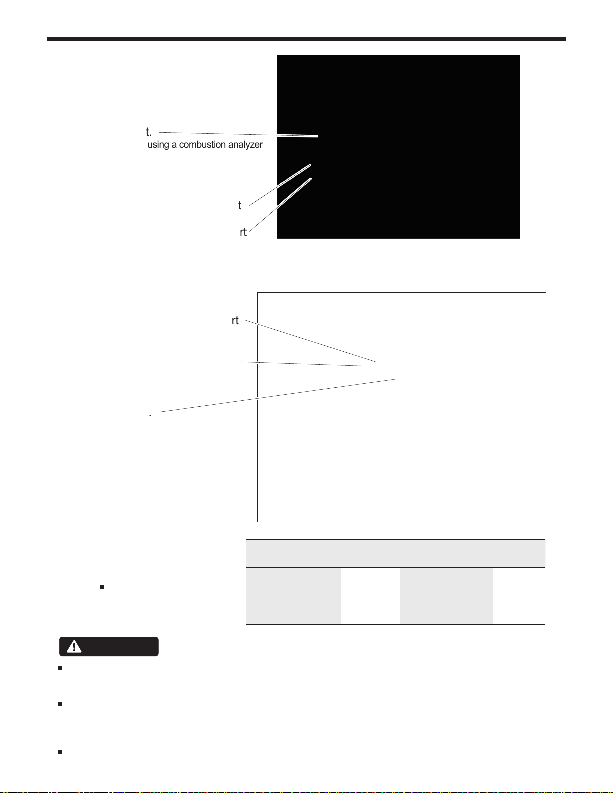
Oset Adjustment.
Do Not Adjust without using a combustion analyzer
to verify adjustment. Adjust ONLY when in MIN Fire
and when using a combustion analyzer.
See Section 4.12 for step by step details.
Gas Outlet / Manifold Pressure Port
Inlet Gas Pressure Port
FTCW140
FTCW199
Gas Outlet / Manifold Pressure Port
Inlet Gas Pressure Port
Oset Adjustment.
Do Not Adjust without using a combustion
analyzer to verify adjustment. Adjust
ONLY when in MIN Fire and when using a
combustion analyzer.
See Section 4.12 for step by step details.
The Maximum and Minimum
gas line pressures must be at
Max Fire operation.
LP Gas Natural Gas
Maximum Pressure 13.0" WC Maximum Pressure 10.5" WC
Minimum Pressure 8.0" WC Minimum Pressure 3.5" WC
Table 9. Gas Pressures
CAUTION
The appliance and its individual shut-o valve must be disconnected from the gas supply piping system during any
pressure testing of the system at test pressures in excess of 1/2 psi (3.5 kPa).
The appliance must be isolated from the gas supply piping system by closing its individual manual shuto valve
during any pressure testing of the gas supply piping system at test pressures equal to or greater than 1/2 psi (3.5
kPa).
Loosen the pressure port screws before you check the gas inlet pressure.
Page 35
The FT Series Wall Mounted, Combination Boiler
Document 4288D
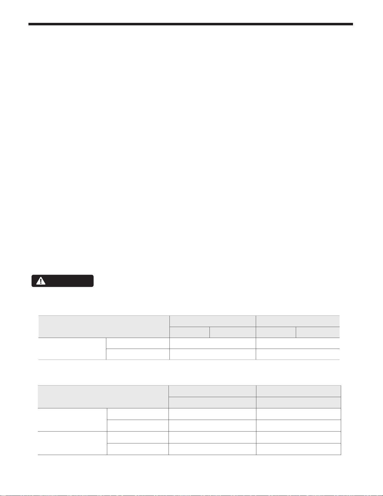
NOTE: Installer is required to verify combustion settings as part of the installation process.
CO should not exceed 200 ppm.
4.12 Adjusting Combustion
Page 35
1. Using a Phillips screwdriver, remove the 4 screws
on the front cover and remove cover.
2. Turn ON the GAS and WATER supply to the FT.
3. Turn ON the FT.
4. Ensure your mascot FT is set for the correct
altitude. The default setting is for altitudes of
0~1,999 ft above sea level. If your Mascot FT is
installed at an altitude of 2,000 ft,or greater the
correct altitude setting should be set according
to Section 4.13 of the Mascot FT Install and
Operating Manual (document #1318) before you
continuing tuning this unit.
5. Connect a manometer to the manifold pressure
port. For dual port manometers, use the positive
pressure side. Check for proper manifold gas
pressure. Refer to table below.
6. Establish a call for heat. You may need to
disconnect the outdoor reset if you are making this
gas conversion during warm weather.
7. Setup your combustion analyzer and place the
sensor into the combustion test port
8. Per Table B for Max Fire, change dip switch 6 to
ON and 7 to OFF. The unit will cycle up to MAX
re.
9. WAIT for your combustion analyzer to stabilize.
This may take up to 3 minutes depending on
your combustion analyzer. Then check the CO2
measurement for MAX re. Refer to Table 10 for
acceptable MAX re combustion readings Do
NOT attempt to adjust CO2 at MAX Fire.
ONLY adjust CO2 in MIN Fire operation.
10. Per Table B for MIN Fire, change dip switch 6 to
OFF and 7 to ON. The unit will cycle down to MIN
Fire.
11. WAIT for your combustion analyzer to stabilize.
Then check the CO2 measurement for MIN
re. Refer to Table 10 for acceptable MIN re
combustion readings
12. Open the Gas Valve Adjustment Port by removing
the cap screw with a 4mm Allen wrench.
13. Then use the 4 mm Allen wrench to make a
minor adjustment (1/8 turn) to either increase or
decrease CO2. See 4.11 on page 34
WARNING
NOTE: Installer is required to verify combustion settings as part
of the installation process. CO should not exceed 200 ppm.
2
CO
value
FTCW (ALL Sizes)
( and all altitudes)
Table C
Table 10. CO2 Values
Manifold pressure
FTCW140
FTCW199
MAX FIRE 8.5 - 10.5% 9.5 - 11%
MIN FIRE 8 - 10% 9 - 10.5 %
MAX FIRE
MIN FIRE
MAX FIRE
MIN FIRE
Natural Gas (NG) Propane Gas (LP)
2˝ VENT 3˝ VENT 2˝ VENT 3˝ VENT
‘NG’ type combustibility ‘LP’ type combustibility
2"/3" VENT 2"/3" VENT
-0.216
0.002
-0.314
-0.015
"
WC -0.216" WC
"
WC
"
WC -0.173"WC
"
WC -0.015"WC
Standard Factory Setting is for
MAX Fire. 9.0% CO2 @ 0-2,000 ft
altitude (Natural Gas).
0.079
"
WC
Table 11. Manifold Pressures
Page 36
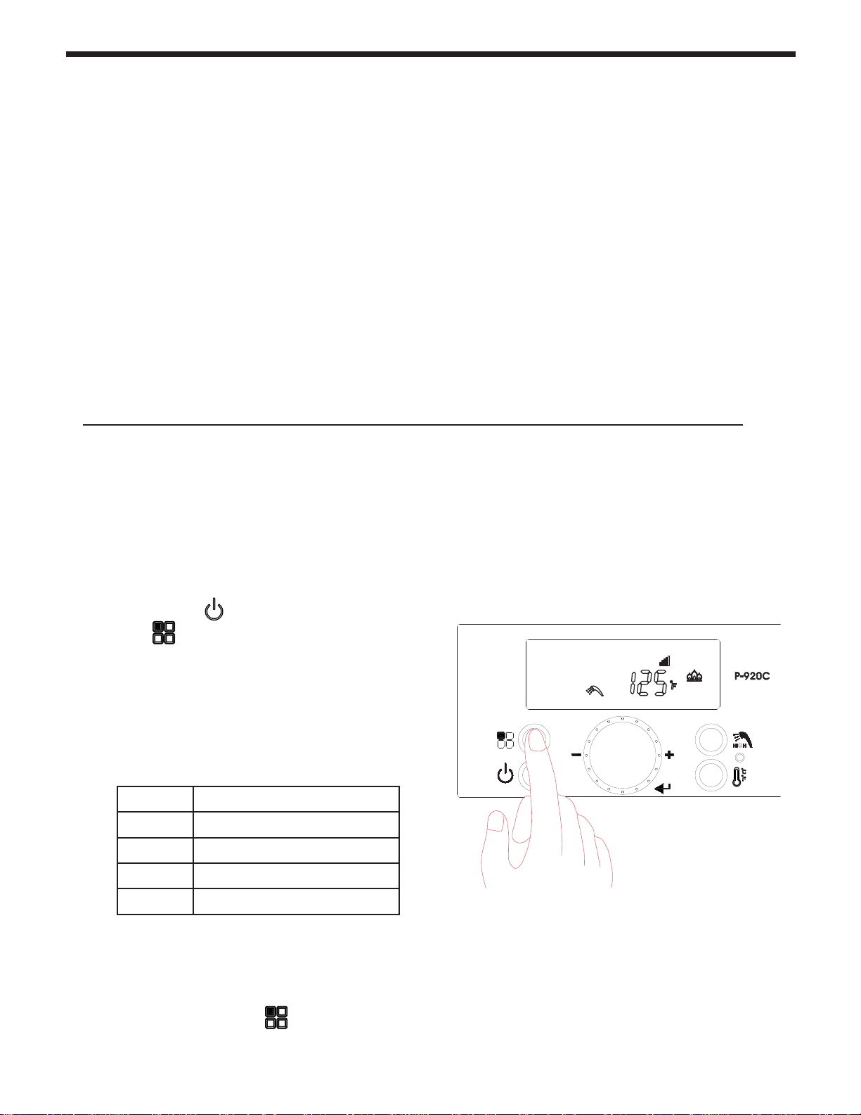
Page 36
14. It may be necessary to go back and forth
between HI Fire and LOW Fire several times (and
adjusting only at LOW Fire), before CO2 at both
are within acceptable levels. Be sure to put the
adjustment port cap screw back onto the valve
when done.
16. Remove your combustion analyzer from the Test
Port and be sure to thread the Test Port plug back
into position.
17. Re-connect outdoor reset if it was disconnected,
put the boiler cover back on and assemble/tighten
the 4 screws that hold the cover in place.
15 Once the CO2 and manifold pressure
measurements for both MIN and MAX Fire are
acceptable per Table C, set DIP switches 6 and
7 to the OFF position for Nominal Fire (normal
operation).
4.13 High Altitude Installations. 2,000’ to 10,000’
The FT is shipped with a default factory setting for installation at an altitude of 0 to 2000’ (approx). For
maximum eciencies at higher altitudes (2,000’ to 10,000’), the FT does have an adjustment in the
Installer Parameters Mode.
Follow these instructions if your installation is at 2,000’ - 10,000’.
1. With the Power turned OFF, press the 'Modes
button' for 5 seconds to get into the Installer
Parameters Mode.
2. Turn the dial (E) until ‘28:HA’ appears.
3. Press the dial (E).
4. Set the high altitude value by turning the dial.
# Altitude of Installation
0 0~1999 ft (0~609 m)
1 2,000~4,499 ft (610~1,645 m)
2 4,500~7,699 ft (1,646~2,346 m)
4 7,700~10,000 ft (2,347~3,048 m)
Refer to table.
5. Press the dial again (E) to save the setting.
6. Press the ‘Modes button’ for one second, to
Save the number and to go back to initial status.
Page 37
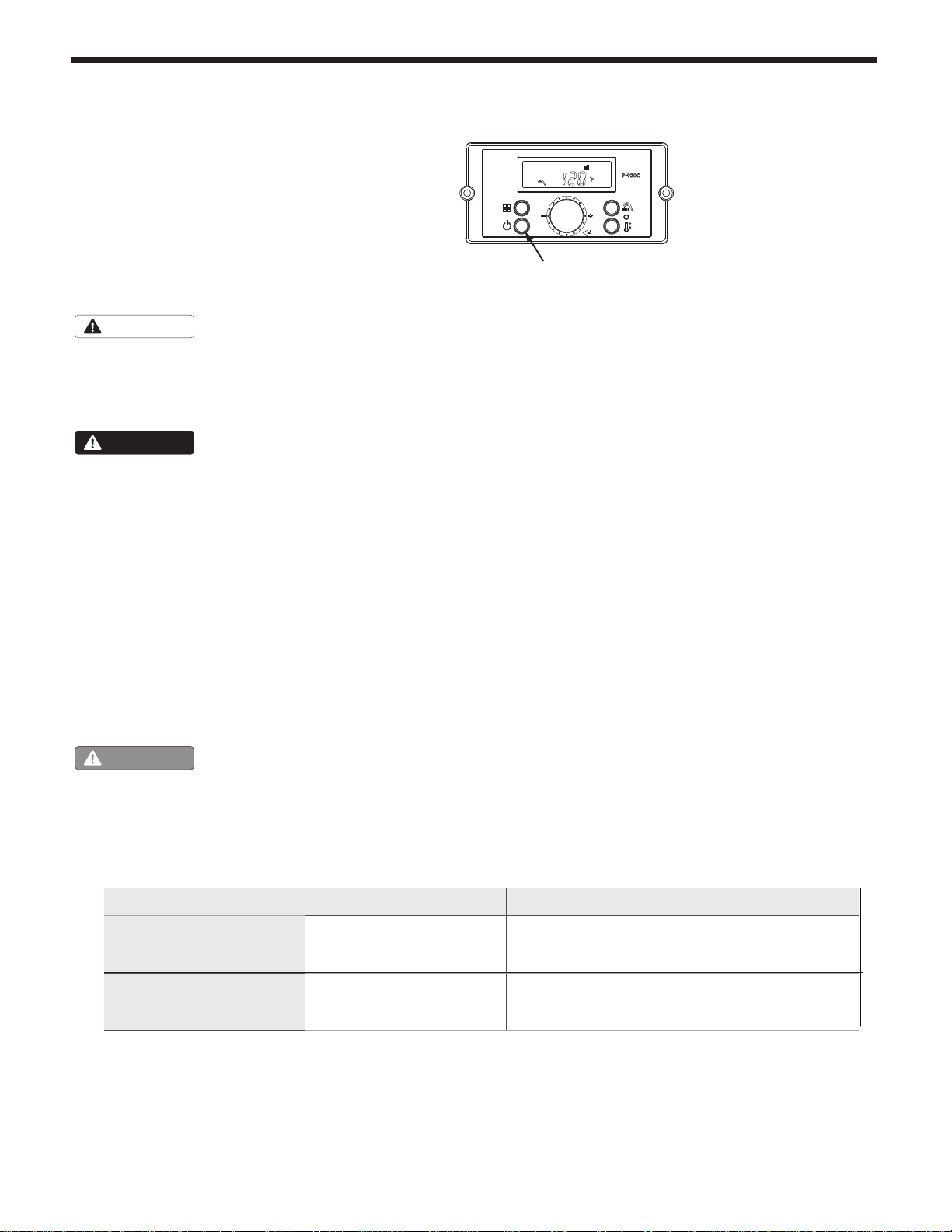
The FT Series Wall Mounted, Combination Boiler
Document 4288D
The FT Series, Wall Combi, Gas Conversion Kit
H2373800D
Kit # R20770
Page 37
4.14 Natural Gas to Propane Conversion
The FT Series, wall combi, condensing boiler is
con gured for Natural Gas (NG) from the factory.
A Natural Gas to Propane Conversion Kit is included
with every FT. The gas conversion kit will show you
how to convert your FT boiler to propane gas. If your
FT does not have the bag containing the conversion
kit, a replacement kit can be obtained. Contact the
manufacturer and request a replacement conversion kit.
NOTICE
If your installation altitude is greater than 2000 ft, check
that the ‘High Altitude’ Installer Setting has been adjusted
to suit your installation altitude. Refer to Section 4.12 of the
Installation and Operation Instructions (Document 1318).
WARNING
This gas conversion kit shall be installed by a quali ed
service agency in accordance with the manufacturer’s
instructions and all applicable codes and requirements of
the authority having jurisdiction. The information in these
instructions must be followed to minimize the risk of re or
explosion or to prevent property damage, personal injury
or death. The quali ed service agency is responsible for
the proper installation of this kit. The installation is not
proper and complete until the operation of the converted
appliance is checked as speci ed in the manufacturer’s
instructions supplied with the kit.Installation must conform
to local codes and the latest edition of the National Fuel
Gas Code, ANSI Z223.1 and CAN-B149.1. Failure to
follow instructions could result in serious injury or property
damage. The quali ed agency performing this work
assumes responsibility for gas conversion.
ON / OFF
Steps 1 thru 12
1. Turn OFF the FT. The ON / OFF button is located at
the bottom left of the Control Display
.
2. Turn OFF the GAS and WATER supply to the FT
(valves are located on the plumbing pipes.)
3. Using a Phillips screwdriver, remove the 4 screws on
the front cover. See Figure A.
4. Locate the Gas Inlet Pipe at the top left of the unit as
shown in Figure A, and loosen the Brass Fittings at
both ends of the Gas Inlet Pipe.
5. Completely unthread the brass tting on the blower end
of the Gas Inlet Pipe and then carefully swing the Gas
Inlet Pipe to the left or right, just enough so that it is out
of the way. See Figure B.
This combination boiler has already been set to burn natural
gas, but can be converted to burn LP gas. Before placing the
combination boiler into operation, verify that the type of gas
supplied to your combination boiler.
CAUTION
Model Natural Gas (NG) part # Propane Gas (LP) part #
FTCW140
FTCW199
Table A. Gas Conversion Parts
6. Remove the existing natural gas nozzle or ori ce. If
your unit is a 199, note that the at side of the ori ce is
towards the blower. Save the packing for re-use. See
Figure C.
FT1412N FT1412P
FT1780 FT1802
Nozzle
Ori ce
pg 1 of 4
Page 38
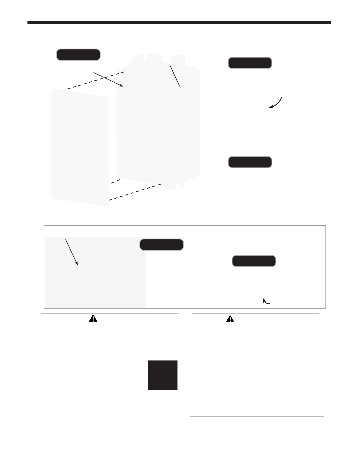
Page 38
Document 4288D
The FT Series, Wall Combi, Gas Conversion Kit
Figure A
Gas Valve
FTCW140
Figure B
Combustion
Test Port
Figure C
Gas Valve
FTCW199
Figure B
Gas Valve
WARNING
This conversion shall be installed by a quali ed
service agency in accordance with the manufacturer's
instructions and all applicable codes and requirements
of the authority having jurisdiction. If the information
in these instructions is not followed exactly, a re,
an explosion or production of carbon
monoxide may result causing property
damage, personal injury or loss of
life. The quali ed service agency is
responsible for the proper and complete
installation of this kit. The installation is
not proper and complete until the operation of the
converted appliance is checked as speci ed in the
manufacturer's instruction supplied with the kit.
Figure C
ORIFICE
PACKING
A VERTISSEMENT
Ce conversion doit être installé par un organisme de
service conformément aux instructions du fabricant
et tous les codes et les exigences de l’autorité
compétente. Si les informations contenues dans ces
instructions n’est pas suivi à la lettre, un incendie,
une explosion ou de la production de monoxyde
de carbone mais résultat causant des dommages
matériels, des blessures ou des pertes de vie. Le
service est responsable pour la bonne et complète
l’installation de ce kit. L’installation n’est pas correcte
et complète jusqu’à ce que le fonctionnement de
l’appareil converti est véri ée comme spéci é dans
le manuel d’instruction fourni avec le kit.
pg 2 of 4
Page 39
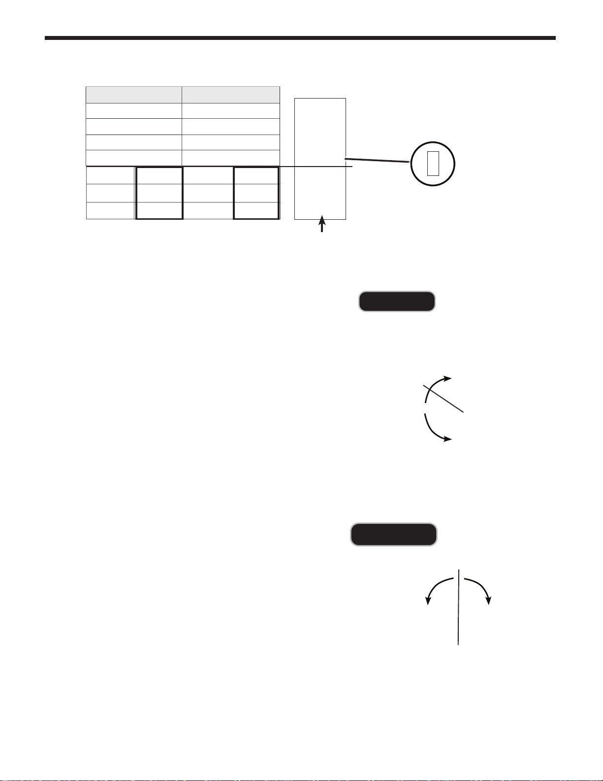
The FT Series Wall Mounted, Combination Boiler
Document 4288D
The FT Series, Wall Combi, Gas Conversion Kit
4.14 Natural Gas to Propane Conversion (continued)
ON OFF
Page 39
MBH 120
Table B DIP Switch Settings
7. Install the new LP (propane) nozzle or ori ce. Re-
8. Return the Gas Inlet Pipe to its original position
MIN Fire Normal Operation
MAX Fire Normal Operation
NG Natural LP Propane
3” Vent Size
ON OFF ON ON
ON OFF OFF ON
OFF ON ON ON
175
140
use the packing from previous.
and tighten both brass ttings.
2” Vent Size
199
Shown is a
Model 140
with 3" Venting
and using
Natural Gas
Figure D
Gas Valve
Adjustment Port
+
9. Per Table B, set DIP Switch 5 to OFF for LP
Propane.
10. Turn ON the GAS and WATER supply to the FT
11. Now start the unit and adjust combustion as
described in Section 4.12
12. Upon completion of set up, write in the correct
Conversion Date and the Technicians Name to
the included gas conversion sticker. See Figure F.
Then apply that sticker adjacent to the rating plate.
Figures E
-
FTCW140
Gas Valve
Adjustment Port
-
+
FTCW199
Page 40
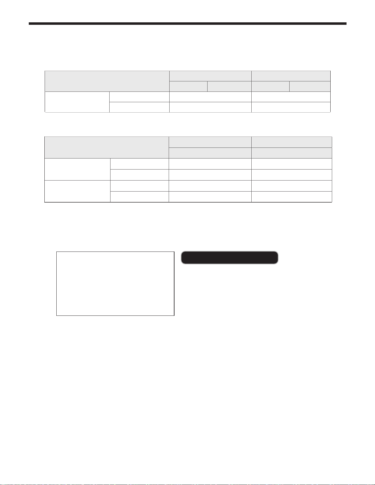
Page 40
Document 4288D
The FT Series, Wall Combi, Gas Conversion Kit
NOTE: Installer is required to verify combustion settings as part of the installation process.
CO should not exceed 200 ppm.
2
CO
value
MAX FIRE 8.5 - 10.5% 9.5 - 11%
2˝ VENT 3˝ VENT 2˝ VENT 3˝ VENT
FTCW (ALL Sizes)
( and all altitudes)
MIN FIRE 8 - 10% 9 - 10.5 %
Table C
‘NG’ type combustibility ‘LP’ type combustibility
Manifold pressure
MAX FIRE
FTCW140
MIN FIRE
MAX FIRE
FTCW199
MIN FIRE
Table D
Natural Gas (NG) Propane Gas (LP)
2"/3" VENT 2"/3" VENT
-0.216
0.002
-0.314
-0.015
"
WC -0.216" WC
"
WC
"
WC -0.173"WC
"
WC -0.015"WC
0.079
"
WC
This unit was converted on ____/____/___to _____gas
with kit #____________by______________________
(name and company __________________________
accountable)_________________________________
___________________________________________
Cette unité a été converti ____/____/____ten ______gaz
en utilisant le kit numéro _____ par______________
(nom et société_________________________________
responsable)___________________________________
_____________________________________________
Figure F (Conversion label)
Page 41
The FT Series Wall Mounted, Combination Boiler
4.15 Plumbing Guidelines
4.15.1 External Plumbing and Water
Connection Guidelines
Page 41
- Ensure pipe material meets local codes and industry
standards.
- The pipe end must be clean and free of debris.
- Do not apply torch heat within 12˝ of the bottom
connections of the unit.
- The DHW inlet and outlet connections are 3/4”.
The CH supply and return connections are 1”. The
system piping must be a min. of 1-1/4” (see Sections
4.15.4 & 4.15.5 for details).
- Isolation valves (shuto valve) will be used.
- All piping should be insulated.
4.15.2 Applicable Backow Preventer
- Apply a backow preventer valve in the DHW supply
inlet (water Inlet) to the unit as required by local
codes.
4.15.3 Diaphragm type Expansion tank
- The air in a diaphragm-type expansion tank is
separated from the water by a exible rubber
membrane. When the tank is installed in and
connected to the piping of the system, water enters
the other side of the tank chamber and presses
down on the diaphragm.
- You should always install an ‘Automatic Air Vent on
the top of the air separator to remove
residual air from the system.
- Automatic air vent has been installed on the inside of
the boiler.
- The installation of an additional air vent is optional.
- If the boiler is installed in a closed water supply
system, such as one having a backow preventer
in the cold water supply line, it will control thermal
expansion.
CAUTION
Use at least the MINIMUM pipe size for the entire
boiler loop piping (connecting boiler to and from
the primary/secondary connection). Use only
primary/secondary piping as shown. Failure to
follow these guidelines could result in system
problems.
CH pipe minimum size : 1 1/4˝
DWH pipe minimum size : 3/4˝
CAUTION
For guidelines in the use of Glycol Products.
Please refer to Section 8.4 on page 74
CAUTION
Scalding Risk: Manufacturer
strongly recommends the
use of an anti-scald mixing
valve at domestic hot water
outlet (boiler location) to
reduce potential for scalding.
Contact Manufacturer for
recommended models.
Check with local codes.
__________________________________________
Page 42
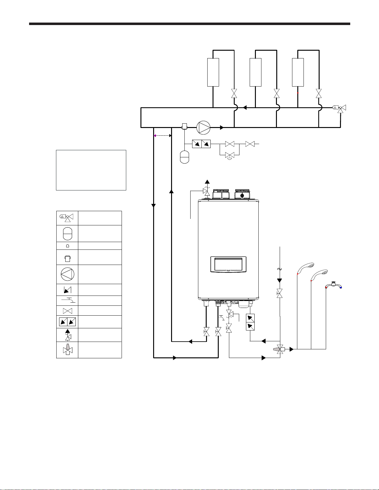
Page 42
PRIMARY LOOP
CH
SUPPLY
CH RETURN
(SPACE HEATING)
ZONE 1
ZONE 2
ZONE 3
1
1
/
4
”
Min
Piping
Do not
exceed
12"
See
Note
SECONDARY LOOP
(SPACE HEATING)
TO DRAIN
P
Make-Up Water
TO DRAIN
DHW OUTLET
DHW INLET
PRIMARY LOOP
CH
SUPPLY
(SPACE HEATING)
ZONE 1
ZONE 2
ZONE 3
1
1
/
4
”
Min
Piping
Do not
exceed
12"
See
Note
SECONDARY LOOP
(SPACE HEATING)
TO DRAIN
P
Make-Up Water
TO DRAIN
DHW OUTLET
DHW INLET
4.15.4 Zoning with zone valves
- In a valve based system, there is one
circulator pump at the boiler and each
heating zone has a zone valve which opens
when the zone demands.
- Each thermostat is wired directly to the
corresponding zone valve. Contacts in
the zone valves provide a
proper signal to the boiler
when the valve is opened.
Auto Fill Valve
and Backow
Preventer Valves are
NOT included (Field
Supplied).
Differential
P
Pressure By-Pass
Expansion tank
(Diaphragm-type)
Automatic air vent
Air separator
Circulation pump
Check valve
Drain valve
valve
Backflow preventer
Pressure Relief Valve
Anti-scald rated
Mixing Valve
1. This piping diagram is meant to show system piping concept only. Installer is responsible for
all equipment and detailing required by local codes.
2. All closely spaced tees shall be 12” (or 4 pipe dia) center to center spacing.
3. A minimum of 6 pipe diameters of straight pipe shall be installed upstream and downstream
of all closely spaced tees.
4. The minimum pipe size of DHW piping should be 3/4” diameter.
5. Install a minimum of 12 diameters of straight pipe upstream of all circulators.
6. Install a check valve on the return line to the boiler.
7. Manufacturer strongly recommends the use of an anti-scald mixing valve at domestic hot
water outlet (boiler location) to reduce potential for scalding.Contact Manufacturer for
recommended models. Check with local codes.
Page 43
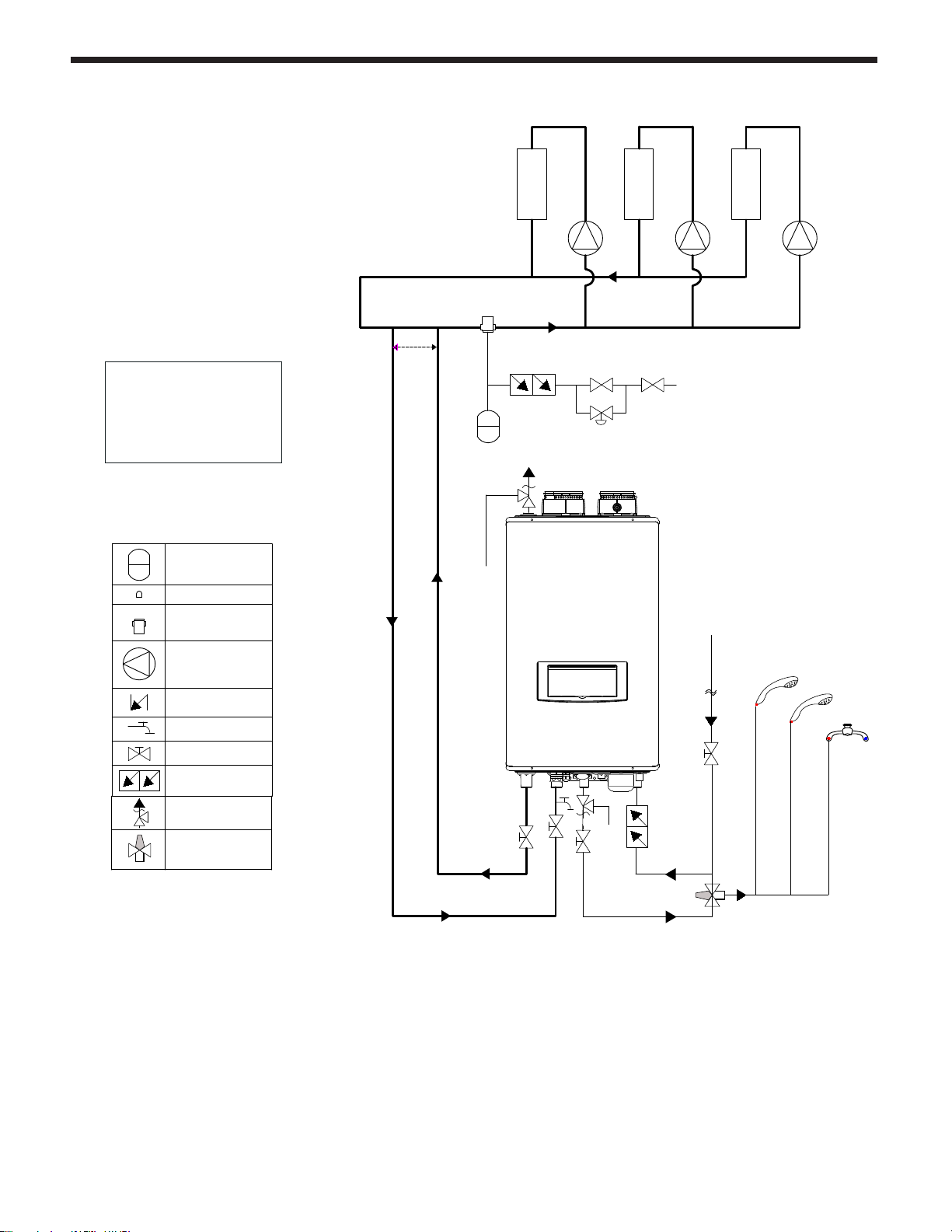
The FT Series Wall Mounted, Combination Boiler
PRIMARY LOOP
CH
SUPPLY
CH RETURN
(SPACE HEATING)
ZONE 1
ZONE 2
ZONE 3
SECONDARY LOOP
(SPACE HEATING)
TO DRAIN
Make-Up Water
TO DRAIN
DHW OUTLET
DHW INLET
1
1
/
4
”
Min
Piping
Do not
exceed
12"
See
Note
PRIMARY LOOP
CH
SUPPLY
(SPACE HEATING)
ZONE 1
ZONE 2
ZONE 3
SECONDARY LOOP
(SPACE HEATING)
TO DRAIN
Make-Up Water
TO DRAIN
DHW INLET
1
1
/
4
”
Min
Piping
Do not
exceed
12"
See
Note
4.15 Plumbing Guidelines (continued)
4.15.5 Zoning with circulation
pumps
- In a pump based system, each heating
zone of has its own circulator pump
which runs when the zone demands.
- Each zone thermostat goes to a
controller which
controls the pumps.
Auto Fill Valve
and Backow
Preventer Valves are
NOT included (Field
Supplied).
Page 43
Expansion tank
(Diaphragm-type)
Automatic air vent
Air separator
Circulation pump
Check valve
Drain valve
Gate valve
Backflow preventer
Pressure Relief Valve
Anti-scald rated
Mixing Valve
1. This piping diagram is meant to show system piping concept only. Installer is responsible for
2. All closely spaced tees shall be 12” (or 4 pipe dia) center to center spacing.
3. A minimum of 6 pipe diameters of straight pipe shall be installed upstream and downstream
4. The minimum pipe size of DHW piping should be 3/4” diameter.
5. Install a minimum of 12 diameters of straight pipe upstream of all circulators.
6. Install a check valve on the return line to the boiler.
7. Manufacturer strongly recommends the use of an anti-scald mixing valve at domestic hot
all equipment and detailing required by local codes.
of all closely spaced tees.
water outlet (boiler location) to reduce potential for scalding.Contact Manufacturer for
recommended models. Check with local codes.
Page 44
Page 44
4.16 Pressure Relief Valve
External pressure relief valves must be installed.
Observe the following. Failure to comply with the
guidelines on installing the pressure relief valve and
discharge piping can result in personal injury, death
or substantial property damage.
WARNING
Do not operate this appliance before the pressure
relief valve supplied is installed with sucient relieving
capacity in accordance with the ASME Rating Plate on
the boiler.
This hot water boiler is provided with 30 psi safety relief
valve that complies with the ANSI/ASME Boiler and
Pressure Vessel Code, Section IV (“Heating Boilers).
(Model : CASE ACME F-82)
This safety relief valve (30 psi) is shipped loose for eld
installation.
An approved ASME HV Pressure Relief Valve must be
installed on the DHW supply line as close to the unit
as possible. Valve size 3/4”, maximum 150 psi. Not
included with boiler.
For safety, the relief valve(s) must be installed into it’s
designed location and not be removed or plugged.
Failure to comply with the guidelines on installing the
pressure relief valves and discharge piping can result in
personal injury, death or substantial property damage.
Direct the discharge piping of the pressure relief valve
so that hot water will not splash on anyone or any
nearby equipment. Attach the discharge line to the
pressure relief valve and run the end of the line within
6-12″ (150-300mm) of the oor.
WARNING
DO NOT install a CH pipe line relief valve with a
pressure higher than 30psi and DHW pipe line relief
valve with a pressure higher than 150psi. This is
the maximum allowable relief valve setting for the
combination boiler.
Ensure that the maximum BTU/H rating on the
pressure relief valve is equal to or greater than the
maximum input BTU/H rating of the combination
boiler.
Pressure Relief Valve must be installed on the CH
supply line & DHW outlet line as close to the unit as
possible. (CH supply line: maximum 30psi, DHW
outlet line : maximum 150psi). No other valves should
be placed between the pressure relief valve and the
appliance.
This appliance has a high-temperature shut o switch
built in as a standard safety feature .Therefore a
“pressure only” relief valve is required.
3/4” 30psi Relief Valve
Test the operation of the valve after lling and
pressurizing system by lifting the lever. Make sure the
valve discharges freely. If the valve fails to operate
correctly, replace it with a new relief valve. Ensure that
the discharge capacity of the pressure relief valve is
equal to or greater than the maximum pressure rating
of the combination boiler.
Page 45
The FT Series Wall Mounted, Combination Boiler
4.17 Disposal of Condensate
High eciency gas condensing Boilers create
condensation when operating. Condensation has
acidic (pH) of approximately 4-5.
Condensate must be drained in accordance with all
local regulations. Follow your local code with regards
to the disposal of condensation.
One of 4 disposal methods must be followed
1. to oor drain
2. to neutralizer (optional kit)
3. to laundry tub
4. to condensate pump (eld supplied)
If a neutralizer is installed, periodic replacement of the
lime stone (or neutralizing agent) will be required. The
rate of depletion of the lime stone varies upon usage
of the boiler. During the rst year of operation, please
check the neutralizer every few months for depletion.
Page 45
Condensate
Trap
Apply only corrosion-resistant materials for the
condensate drain lines such as 1/2˝ PVC, CPVC,
Polypropylene pipe or included plastic hose.
Category II & IV water heaters must be installed with a
means provided for the drainage of condensate.
Catégorie II & ; IV chaue-eau doit être installé
avec une moyens prévus pour l’évacuation des
condensats.
Condensate is mildly acidic (pH=5), and may harm
some oor drains and/or pipes, particularly those
that are metal. Ensure that the drain, drainpipe, and
anything that will come in contact with the condensate
can withstand the acidity, or neutralize the condensate
before disposal. Damage caused by failure to install
a neutralizer kit or to adequately treat condensate
will not be the manufacturer’s responsibility.
Contact Manufacturer to order
Neutralizer Kit# A2123601
_________________________________________
NOTICE
AVIS
CAUTION
Condensate
drain pipe
1
(View is as if side panel
were removed)
2 3
4
Page 46

Page 46
4.18 DHW Flow Restrictors
Flow Restrictors are factory installed. Rated at 3.2
GPM for the model 140 and 7.0 GPM for the model
199, both of these factory installed restrictors are white
in color. For the 140, an additional ow restrictor,
rated at 4.5 GPM, is blue in color and is packaged with
the Product Accessories. See Section 1.
If 3.2 GPM is not sucient for your model 140
installation, replace the factory installed white ow
restrictor with the blue ow restrictor by following these
instructions.
To replace the Flow Restrictor.
1. Being sure that the unit is completely shut o and
drained, locate the DHW inlet adapter on the bottom
of the appliance.
2. Pull the two pins to release the DHW inlet lter. See
Illustration. The ow restrictor is attached to the top
of the lter assembly.
3. Remove the installed white ow restrictor and
replace it with the blue ow restrictor included with
the Product Accessories.
4. Reinstall the DHW inlet lter.
5. Re-insert the two pins.
6. Rell and restart your FT as per the Installation
Instructions.
WARNING
If the appliance has been lled and operational,
then the gas, water and power must be completely
shut o, and the unit must be drained before
proceeding with this instruction. See Section 8 of
this installation book.
Failure to do so could result in substantial
property damage, sever personal injury, or death.
Flow Restrictor
Shown is the 140. The 199 is very similar.
Page 47
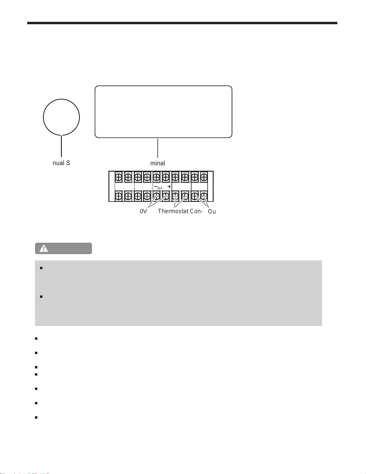
The FT Series Wall Mounted, Combination Boiler
4.19 Electrical Wiring Connections
FTCW140
Page 47
Manual Switch
L N T T
External Input
Terminal Block
0 - 10V
0-10V
INPUT
O / S
Thermostat Con-
nection
Outdoor
Sensor
WARNING
Install wiring and electrically ground boiler in accordance with authority having jurisdiction or, in the absence
of such requirements, follow the National Electrical Code, NFPA 70, and/or CSA C22.1 Electrical Code-Part
1 in Canada.
ELECTRICAL SHOCK HAZARD — For your safety, turn o electrical power supply at service entrance panel
before making any electrical connections to avoid possible electric shock hazard. Failure to do so can cause
severe personal injury or death.
This appliance must be electrically grounded. Ensure the electrical receptacle that the combination boiler will
be plugged into, is properly grounded; if wiring directly.
Do not attach the ground wire to either the gas or the water piping as plastic pipe or dielectric unions may
isolate the Combination boiler electrically.
The wiring diagrams contained in this manual are for reference purposes only.
Refer to these diagrams and diagrams from external controls used with this appliance. Read, understand,
and follow all wiring instructions.
Do not disconnect the power supply when the unit is in normal operation. Damage caused by freezing is not
covered under the warranty.
Manual(Rocker) switch maximum allowable current for each circulator is 1.6 amps at 125VAC.
( Housing : Nylon #66 UL 94V-2 , Rocker : Nylon #66 UL 94V-2, Terminal : Copper Alloy )
Terminal block (External power connector) : DFT-20A-10P (20 amps at 300VAC)
Page 48
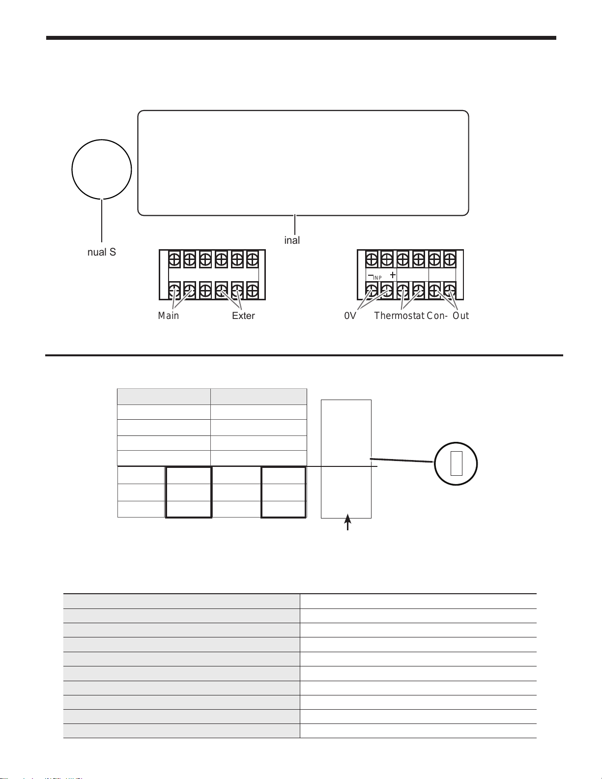
Page 48
Document 4288D
The FT Series, Wall Combi, Gas Conversion Kit
Table B DIP Switch Settings
Shown is a
Model 140
with 3" Venting
and using
Natural Gas
MBH 120
140
175
199
ON OFF
MIN Fire Normal Operation
MAX Fire Normal Operation
NG Natural LP Propane
3” Vent Size
2” Vent Size
ON OFF ON ON
ON OFF OFF ON
OFF ON ON ON
4.19 Electrical Wiring Connections (cont)
FTCW199
Manual Switch
Terminal Blocks
MAIN POWER
External
Main
Power
CH/BOILER PUMP
CH Pump
4.20 DIP Switches
0 - 10V
External Input
0-10V
INPUT
T T
O / S
Thermostat Con-
nection
Outdoor
Sensor
System Control Setting
Maximum ame detecting voltage 2.4V
Pre-purge time (Tp) Maximum 10s, minimum 1s
Safety Time (igniting time) (Ts) 3s
Igniting interval time 10s
Post-purge time (Tip) 120S (1st : 60s + 2nd 60s)
Over-heating 1,2,3 protection detection time <3s
Pump1 post circulating time (T1pv) 60s
Pump2 post circulating time (T1pv) 60s
High & Low Water Level detection time <6s
High & Low Water Level Recover time <6s
Page 49
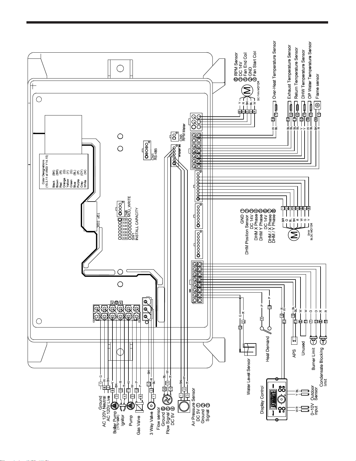
The FT Series Wall Mounted, Combination Boiler
4.21 Control Board, Electrical Diagram
Control Board
Page 49
Page 50
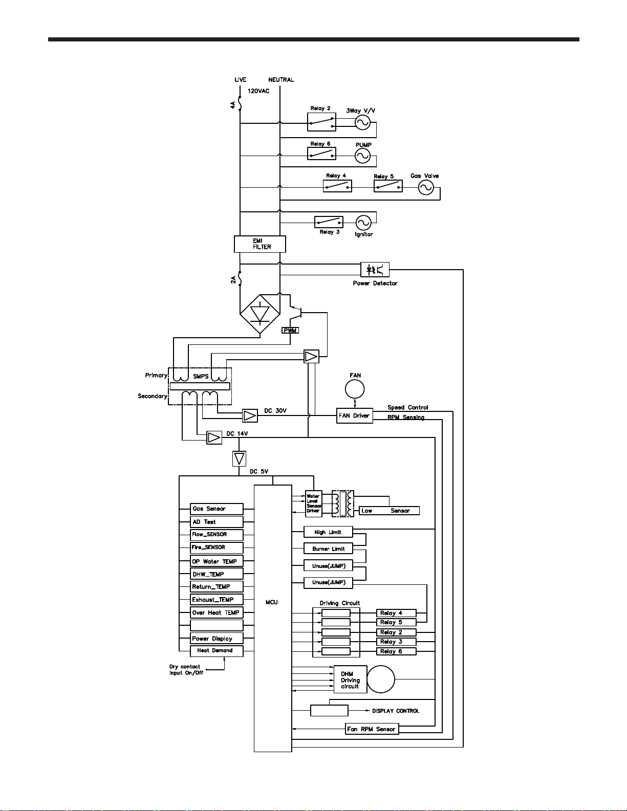
Page 50
F/B
level
Air Pressure Sensor
4.22 Ladder Diagram
Page 51
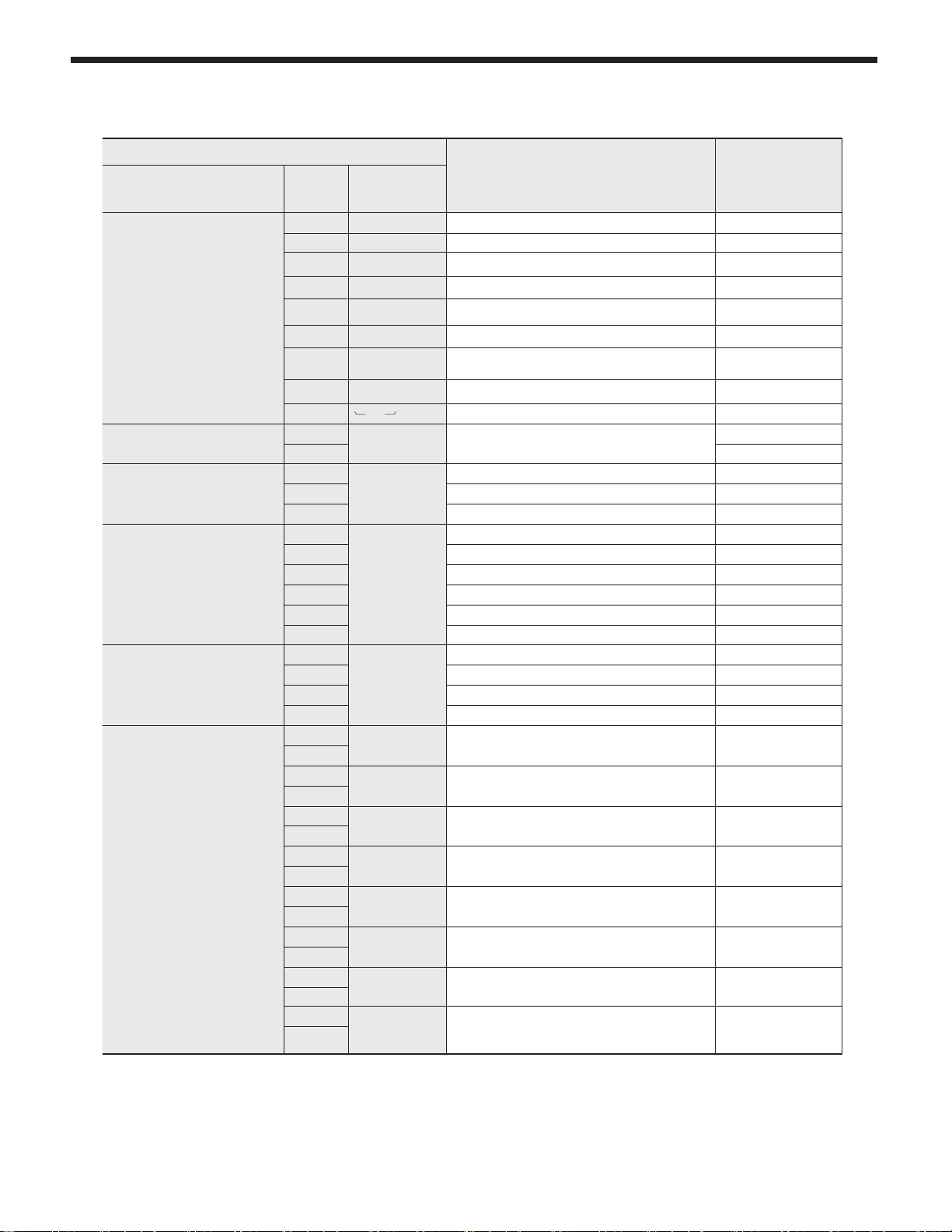
The FT Series Wall Mounted, Combination Boiler
4.23 Electrical Connections
Connector
Description HT SELV
#, Location, Type PIN Label
1 - GROUND HT (120V~)
2 L Power Supply Line HT (120V~)
3 CP1 Not Used HT (120V~)
4 IT Igniter HT (120V~)
CN9
65001WS-12
CN6
LW6A4-03
CN1
SMW250-5D
CN4
LWD1140-06D
CN8
SMW250-04D
CN11
LWD1140-16
5 L(HT) Pump : CH HT (120V~)
6 GV Gas Valve HT (120V~)
7
8 N Power Supply Neutral HT (120V~)
9-12
1
3 HT (120V~)
1
2 GND SELV (5V)
3 RS485 - SELV (5V)
1
2 GND SELV (30V)
3 VDD SELV (14V)
4 Fan power(start coil) SELV (30V)
5 Fan power(end coil) SELV (30V)
6 Fan speed feedback signal SELV (14V)
1
2 ISP /Reset port SELV (5V)
3 ISP TOOL0 Data port SELV (5V)
4 VCC SELV (5V)
1
8
2
10
3
11
4
12
5
13
6
14
7
15
8
16
-
N
CP3/3Way 3 Way Valve
RS-485
FAN
MCU ISP
HWL Not Used SELV (12V~)
LWL Low Water Level Leakage Sensor SELV (12V~)
HD Central Heating Demand SELV (5V)
TH
APS Jump SELV (14V)
EL Jump SELV (14V)
BL Burner Limit SELV (14V)
HL Condensate Block SELV (14V)
- -
AC Power COM Line HT (120V~)
RS485 + SELV (5V)
Not Used -
GND SELV (5V)
Connect to the Display
Control(Thermostat)
Page 51
HT (120V~)
SELV (14V)
Page 52
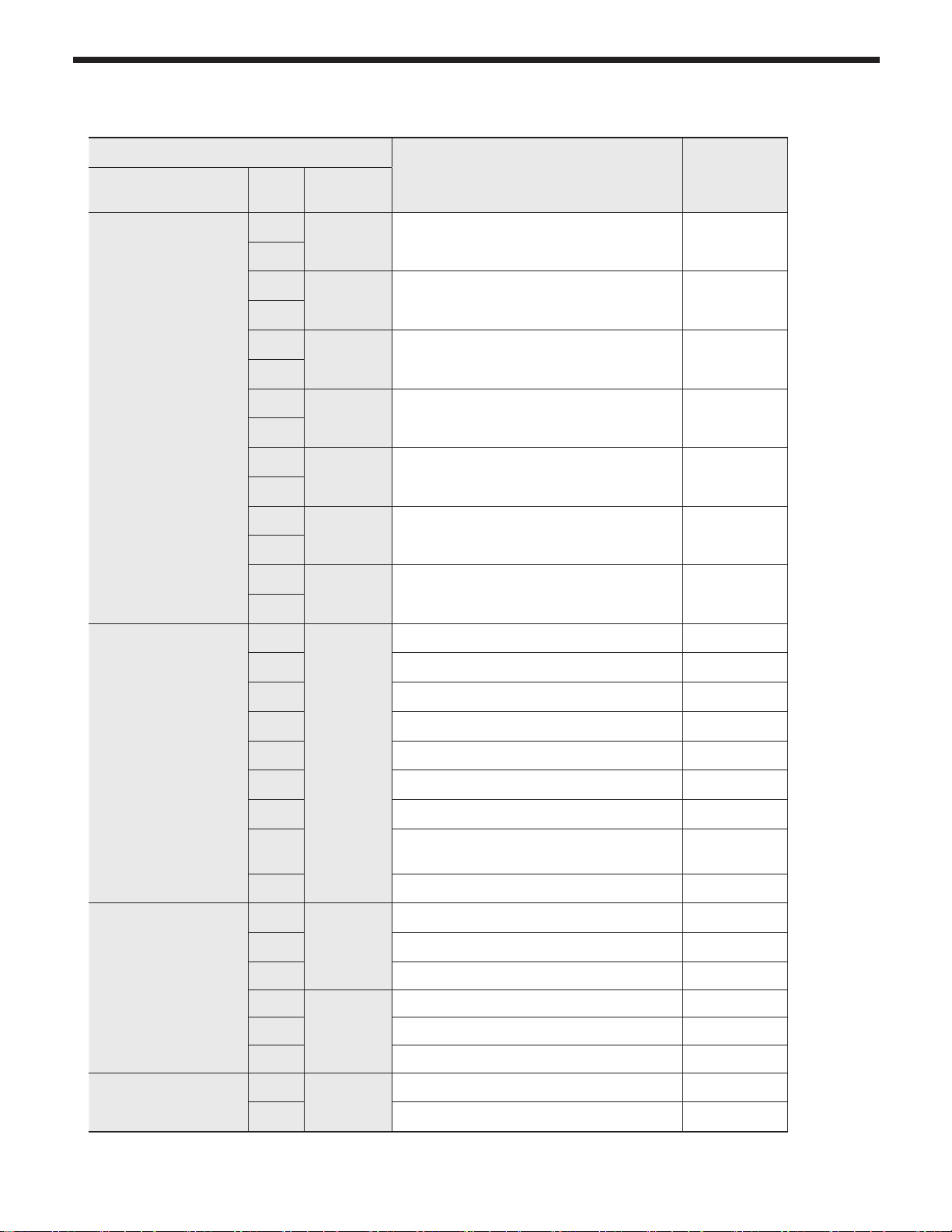
Page 52
Connector
#, Location, Type PIN Label
Description HT SELV
CN7
LWD1140-14
1
8
2
9
3
10
4
11
5
12
6
13
7
14
1
2 DHM Stepper motor position SELV (14V)
F.S Flame Detect Sensor SELV (5V)
OP.S Operating water temperature sensor SELV (5V)
DH.S DHW temperature sensor SELV (5V)
I.S
BG.S Venting (Exhaust) temperature sensor SELV (5V)
ST.S Not Used SELV (5V)
SP.S Over-Heat temperature sensor SELV (5V)
Return temperature sensor SELV (5V)
GND SELV (14V)
CN14
SMW250-09D
CN3
SMW250-06D
CN5
SMW250-10D
3 VDD SELV (14V)
4 DHM Stepper motor coil X phase SELV (14V)
5 DHM Stepper motor coil Y phase SELV (14V)
6 VDD SELV (14V)
7 DHM Stepper motor coil /X phase SELV (14V)
8
9 Unuse -
1
2 GND SELV (5V)
3 Voltage Input SELV (5V)
4
5 Water Flow Sensor SELV (5V)
6 GND SELV (5V)
1
2 GND SELV (5V)
DHM
APS
SENSOR
FLUX1
RPM
DHM power IWM Stepper motor coil /Y
phase
VCC SELV (5V)
VCC SELV (5V)
FAN RPM Check SELV (5V)
SELV (14V)
Page 53
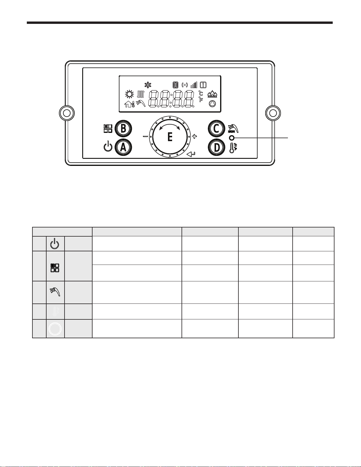
The FT Series Wall Mounted, Combination Boiler
SECTION 5 Control Display and Operation
5.1 Control Dial and Buttons
The Control Display
Page 53
Status Light
(constant green
when operating
normally)
The Control Display has a Control Dial (E), 4 buttons (A, B, C, D), and a Liquid
Crystal Display (with 72 back-lit segments). This section of this manual gives
instruction on how to navigate into the many functions of the FT and to change
temperature set points, set system variables and controller parameters.
Buttons Function Method Function Method
A
B
C
D
E
Display
Power
Modes
Hot
Water
Central
Heat
Scroll /
Select
Turns Control Display ON / OFF Press/Tap
Status Display Mode (With display power on) Press/Hold (5 Seconds)
Installer Mode (WIth display power o) Press/Hold (5 Seconds)
DHW Set-Point LOW Range
95 - 120°F (35 - 49°C)
CH set-point mode (boiler only)
Turn to scroll (clockwise or counterclockwise),
Tap to select
Press/Tap (To return home,
tap Scroll/Select)
Press/Tap (To return home,
tap Scroll/Select)
Press/Tap
Return to Menu (from
Status Display Mode)
Return to o display o
mode (from installer mode)
DHW set-point HIGH
Range 121-140°F (49.5-
60°C) (from DHW set-
point LOW RANGE)
Toggle (°C/°F) (from CH
setpoint mode)
Press/Tap
Press/Tap
Press/Hold (5 Sec-
onds), (To return
home, tap Scroll/
Select)
Press/Hold (5
Seconds)
• Temperature Specications
Operating ambient Temperature Range : -10 to 60°C.
Operating Relative Humidity up to: 90% at 40°C.
Shipping & Storage Temperature Range of : -20 to 80°C.
Page 54
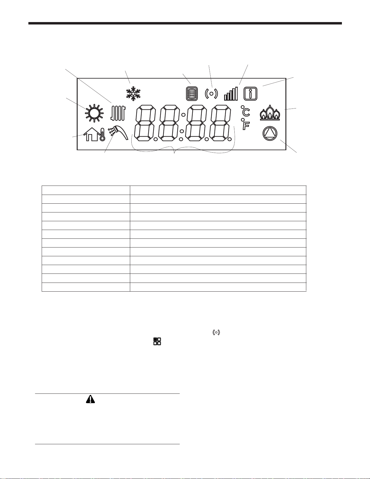
Page 54
5.2 LCD Overview
CH
Central
Heat
Anti-Freeze
Mode
Storage
Heating
Lock Communicating
Summer
Mode
(warm
weather
shutdown)
Outside
Temp Mode
or 0-10V
Domestic Hot Water Mode
CH mode Central Heat mode icon can be adjusted
Anti-freeze mode Anti-freeze mode icon
Storage Heating mode Stored Water Being Heated, can be adjusted
Lock mode Buttons-locked mode icon
Communication Communication icon
Summer mode Only DHW Mode, can be adjusted (warm weather shutdown)
Status and Installer mode The Status Mode or the Installer Mode is Active (all parameters)
Flame signal Flame Signal icon
Pump icon Water pump operation (CH or DHW) icon
Numeric Display Number and character display, to display all parameters
DHW mode Combination boiler Set Point, can be adjusted
Outside temp or 0-10 V mode Operating by outside temperature or 0-10V
Numeric Display
Status and
Installer
Modes
Flame
Signal
Pump
The LCD will illuminate when a user action is detected (a button is pressed) and will turn
back o after 20 seconds.
* NOTE: The display will not allow changes when the lock mode is activated.
To exit the Lock mode, press the
WARNING
button.
Do not use this appliance if any part has been
under water. Immediately call a qualied service
technician to inspect the appliance and to replace
any part of the control system and any gas control
that may have been under water.
Page 55
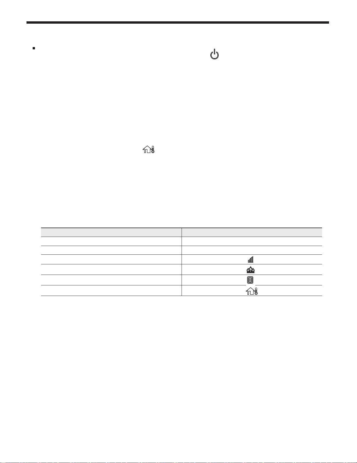
The FT Series Wall Mounted, Combination Boiler
5.3 Operating Mode
Operating Mode
After the Power is turned on, and/or the Control Display is turned on , the Control Display
will go through a ‘Start Up’ checklist and briey show a sequence of diagnostic codes before
entering into the ‘Operating Mode. It will then display the following information.
Page 55
Indicate Example
Current Operating Temperature 110°F
Temperature sign Celsius or Fahrenheit letter °C or °F
Display and Controller are communicating
If ame detected
If pump is operating
Outdoor sensor or 0-10V
Page 56
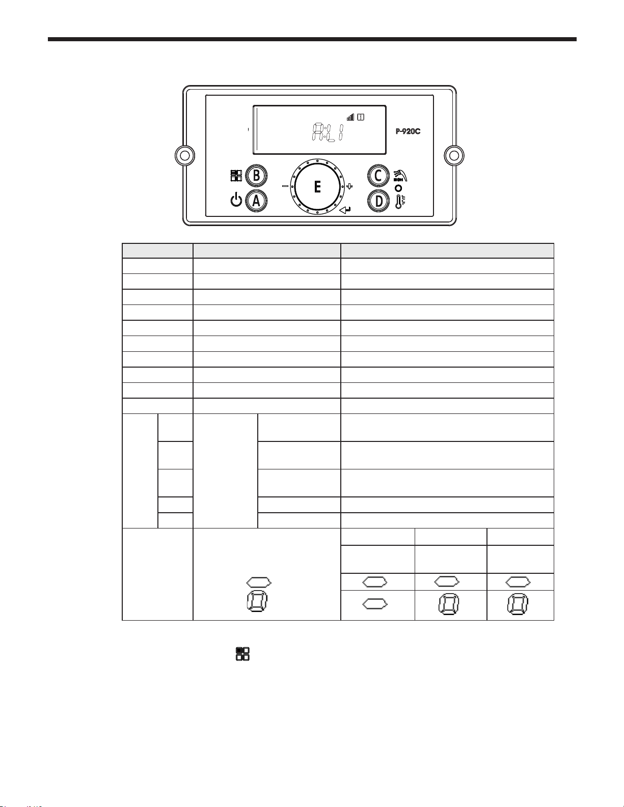
Page 56
AUTODESK � � � � �� � � � �
AUTODESK � � � � �� � � � �
5.4 Status Display Mode
Digital Display Status Display Parameter Description
O:ot Outdoor temperature Current Outdoor temperature
A: Li or A: GA Flow unit Current ow value(Li: L/m, GA: GPM)
b: It CH Return Water Temperature Current Return Water Sensor Temperature
C: Fr Fan rpm Current fan rpm value
d: Lc Lock mode Lock mode ON/OFF
E: oP OP temperature Current OP temperature
F: dH DHW temperature Current DHW temperature
H: Eh Exhaust temperature Current Exhaust temperature
I : St N/A Not Used (Default is 0)
J: oH Overheat temperature Current Overheat temperature
1: PH
2: rh
L: rt
3: rH
4: It Ignition cycles Ignition cycles x 10 times
5: IH Ignition cycles Ignition cycles x 10,000 times
P: Ou
Supply power
time
Burner
Burner
Operation
Time
operation time
Burner
operation time
Displays output condition for
internal primary pump and
three way valve.
- O
Supply power time x 100 hour
Burner operation time x 1 hour
Burner operation time x 1,000 hour
1st Icon 2nd Icon 3rd Icon
Not Used
Internal CH
Pump
3 Way Valve
- On
To change any of the above listed Status Parameters,
Press and Hold Button B
Rotate Dial E until you nd the Parameter that you wish to change. Tap Dial E to enter that Parameter.
Adjust to the setting that you require and then press (tap) Dial E to save and to Exit.
to get into the Status Display Mode.
Page 57
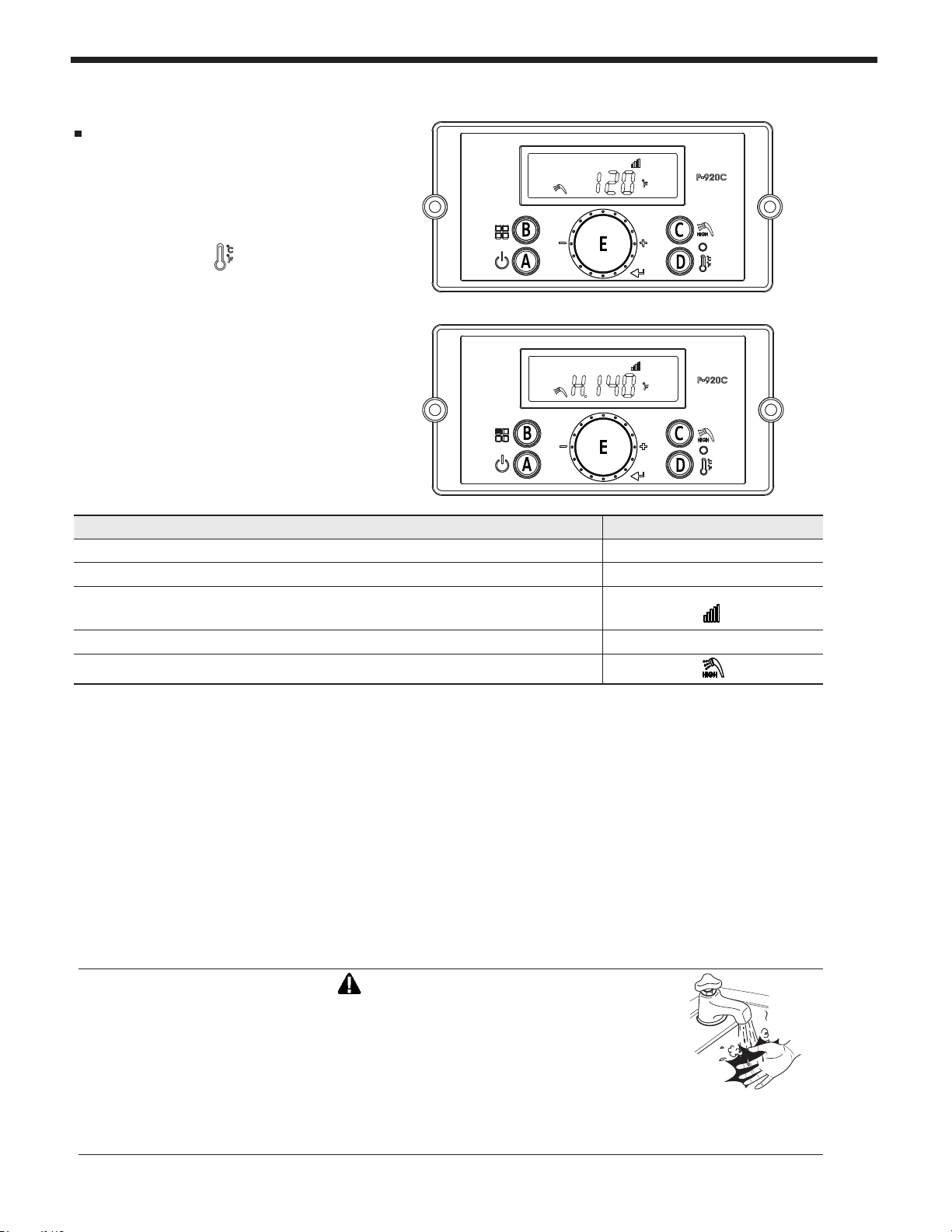
The FT Series Wall Mounted, Combination Boiler
5.5 DHW Set Point Change Mode
DHW Set Point Change Modes
The display shows the following
information when changing water heating
temperature set points.
Changing between Celsius and Fahrenheit
When the button D
than 5 seconds), temperature unit will toggle
between °C and °F.
is pressed (for more
Page 57
Indicate Example
Current DHW set-point temperature 120°F
Temperature sign Celsius or Fahrenheit letter °C or °F
If display is communicating with the main controller normally, the
communication icon will be indicated.
When DHW set-point range is high : from 121°F (49.5°C) to 140°F (60.0°C) H . 140°F
When changing DHW setpoint, the DHW icon will ash S24
* Default DHW set-point is 120°F (49°C)
• DHW 95-120°F (35 - 49°C) LOW range (Default)
-To change LOW range, press the C Button. The DHW icon and current DHW LOW will ash (a ashing
value means it can be changed).
-Turn dial E clockwise to increase and counterclockwise to decrease until desired temperature is reached.
-Press dial E to save setpoint changes.
• DHW 121 - 140°F (49.5 - 60°C) HIGH range
-To change HIGH range, press and HOLD the C button for more than 5 seconds. The DHW icon and
current DHW HIGH will ash (a ashing value means it can be changed).
-Turn dial E clockwise to increase and counterclockwise to decrease until desired temperature is reached.
-Press dial E to save setpoint changes and to Exit.
DANGER
Scalding may occur within 5 seconds at a setting of 140°F (60°C). Water temperatures
over 125°F can cause severe burns, or death from scalding. Children, disabled,
and elderly are at highest risk of being scalded. Read all instructions before setting
temperature at appliance. Feel water before bathing or showering.
Manufacturer strongly recommends the use of an anti-scald mixing valve at domestic hot
water outlet (boiler location) to reduce potential for scalding.Contact Manufacturer for
recommended models. Check with local codes.
Page 58
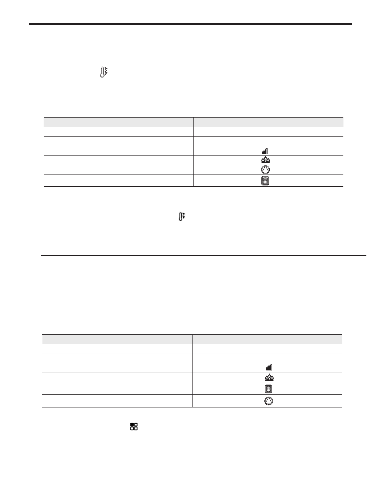
Page 58
5.6 CH Set Point Change Mode
Changing between Celsius and Fahrenheit
When the button D
5 seconds), temperature unit will toggle between
°C and °F.
Indicate Example
Current Operating Temperature 110°F
Temperature sign Celsius or Fahrenheit letter °C or °F
Display and Controller are communicating
If ame detected
If pump is operating
When changing CH Setpoint, the CH Icon will ash
Default CH set-point is 120°F (49°C)
CH set-point range is 86 - 180°F (30.0 ~ 82.0°C)
To change CH Setpoint, press the D
CH Setpoint will ash.
Turn the E dial clockwise to increase, and counterclockwise to decrease CH setpoint, until
desired temperature is reached.
Press E dial to save changes and to Exit.
is pressed (for more than
button. The CH Icon and current
5.7 Storage Mode
Indicate Example
Current Operating Temperature 110°F
Temperature sign Celsius or Fahrenheit letter °C or °F
Display and Controller are communicating
If ame detected
Storage mode indication
If Pump is operating
To change Storage Mode Temp, First turn OFF the power to the Control Display.
Then Press and Hold Button B
Rota te Dial E until you nd 5:St Tap Dial E to enter Storage Mode. Storage Mode indicates that the boiler
is heating the water held in the internal storage tank. When Storage Mode is active, the display will
appear as shown.
Turn the E dial clockwise to increase, and counterclockwise to decrease setting.
Press E dial to save changes and to Exit.
to get into the Installer Mode.
Page 59
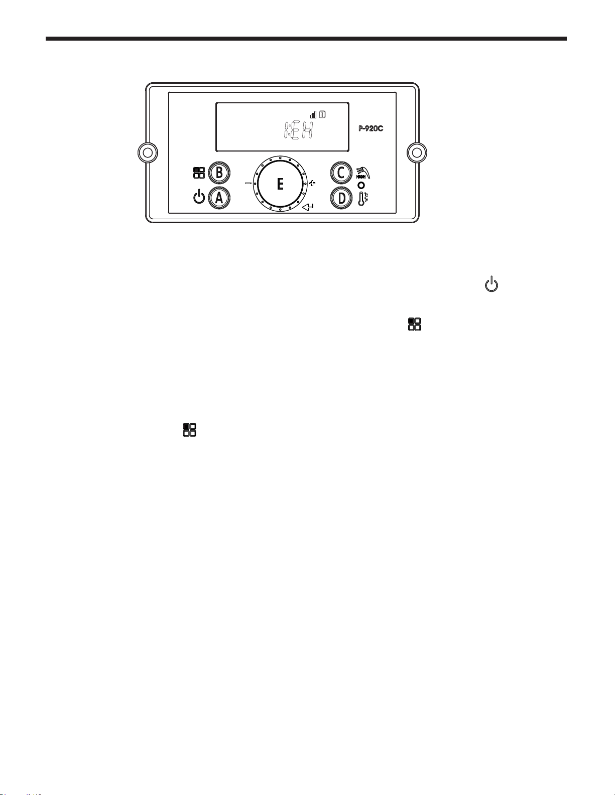
The FT Series Wall Mounted, Combination Boiler
AUTODESK � � � � �� � � � �
AUTODESK � � � �� � � � � �
5.8 Installer Parameters
These changes are to be made only by a qualied technician.
Page 59
To c hange any of the Installer Parameters,
Start by turning OFF the Power
to the Display Control.
Then, with the power OFF, Press and HOLD (more than 5 seconds) the Button B to get into the
Installer Mode.
Rotate Dial E until you nd the Installer Parameter (full list on facing page) that you wish to change.
Tap Dial E to enter that Parameter.
Adjust to the setting that you require and then press (tap) Dial E to save and to Exit.
Finish by pressing button B
Page 60
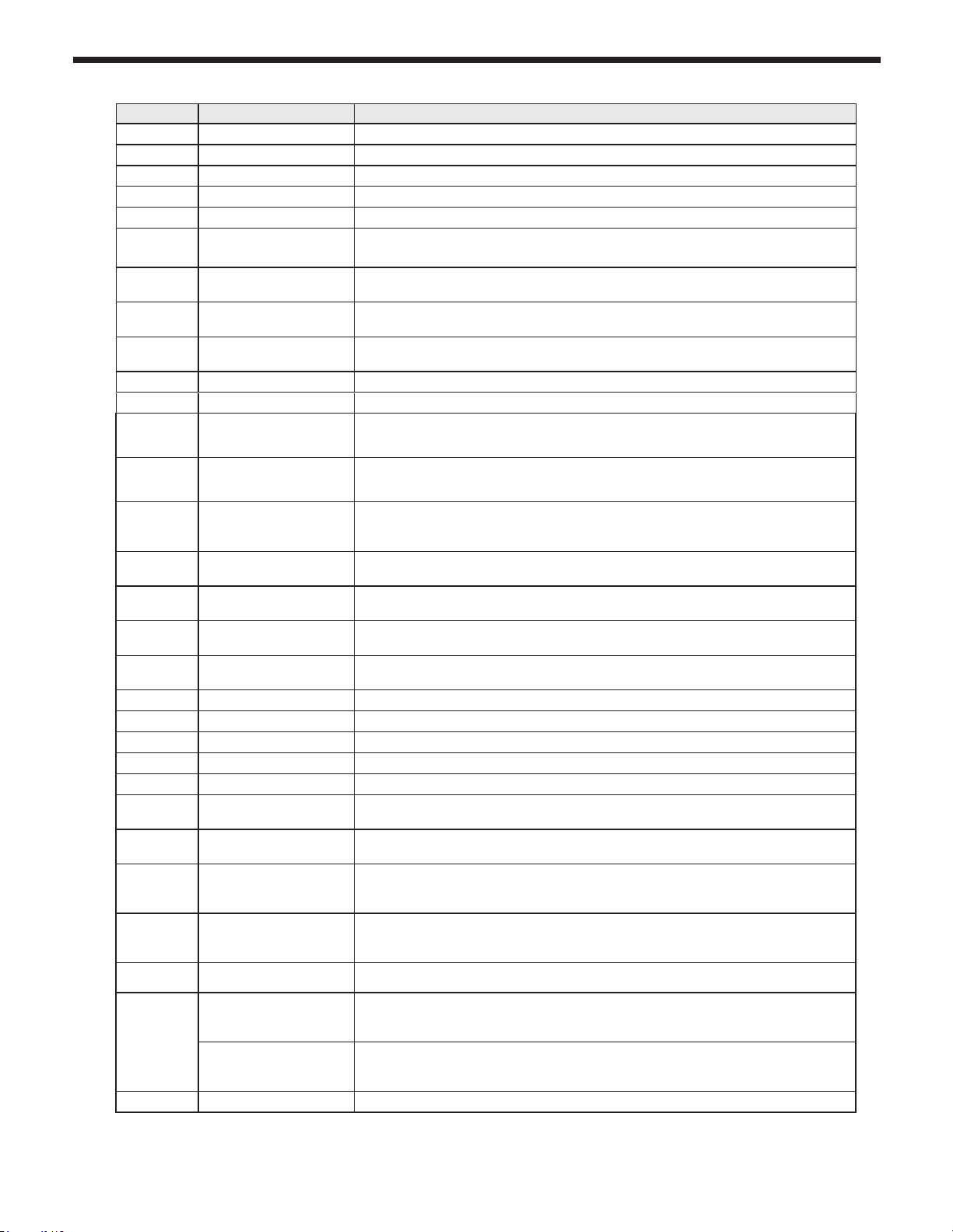
Page 60
5.8 Installer Parameters
Index Parameter Description
1: EH
2: cE
3: In
4: Fu
5: St
6: OH
7: OL
8: FH
9: FL
10: dr
11: dI
12: bt
History entry History fault code (E0~E9)
Clear Error History Clearing of error History buer
System initialize System initialize to default
Flow unit gallon / liter
Heat storage function Heat storage function On/O
Maximum Outdoor
Temperature
Minimum Outdoor
Temperature
Max fan
Min fan
Delete running time Delete running time
Delete igniting times Delete igniting times
Outside Unit Function
Delay Time (boost time)
Range: (Minimum Outdoor Temperature + 9°F) to 110°F Default 68°F (20°C)
Range: -4°F to (Maximum Outdoor Temperature -9°F)
Adjusts Maximum Fan Speed
Range: -30 - +30
Adjusts Minimum Fan Speed
Range: -30 -+30
When heating in the outside unit function for the rst time, there will be a delay.
(0~120 min, Default 0)
13: Ft
14: bo
15: OF
16:cH
17:cL
18:dH
19:cb
20:db
21:PP
22:Po
23:PF
24:SF
25:So
26:dt
27:PE
28: HA
29: AP
30: dP
Delay time for heating
burner operation
Setting temperature of
burner ON.
Warm Weather Shutdown
Setting for Heating
Maximum Temperature
Setting for Heating
Minimum Temperature
Setting for Hot Water
Maximum Temperature
Heating Combustion Rate 50%~100%, Default 100%
Hot Water Combustion Rate 50%~100%, Default 100%
Pump Post-Purge Time (Heating Pump) 1min ~ 60min, Default 40min
Pump on Time (Heating Pump Repeat ON Time) 1 min ~60 min, Default 5 min
Pump o Time (Heating Pump Repeat O Time) 0min ~60 min, Default 10 min
Heat storage o
Temperature
Heat storage on
Temperature.
Delay time when switching
from DHW mode to CH
mode
Internal CH Pump PostPurge Time,
T/T Satised
High Altitude setting (Normal)0<1<2<4 (High)
Internal CH Pump and
3-way valve Pump Test
Mode
Internal CH Pump and
3-way valve Pump Test
Mode
DHW Timeout Feature Range: 0~12 time, '0' OFF, Default: 4 time
Burner does not operate during the delay time when the burner is turned o due to the
temperature during heating operation. (0~20 min, Default 1 min)
Heating temperature setting during heating operation –
Operate in burner ON temperature setting Range:
-12.7°C(9°F)~-2.7°C(27°F), Default 2.7°C(27°F)
This warm weather temperature setting will shut down CH Mode 10°C(50°F)~43°C(110°F),
Default 38°C (100°F)
Range: 9°F less than Minimum Temperature to 180°F, Default 180F
12.7°C less than Minimum Temperature to 82°C, Default 82°C
Range: 86°F to 9 degrees °F less than Maximum Temperature, Default 86°F
30°C to 12.7degrees °C less than Maximum Temperature, Default 30°C
49°C(120°F)~60°C(140°F), Default 60°C(140°F)
60°C(140°F)~75°C(167°F),Default(70°C)158°F
(o Temperature-Setting Temperature) -12.7°C(9°F)~2.2°C(36°F),
Default (-2.7°C) 27°F
Range: 0 – 2 minutes,Default 2min
Allows the user to set the appliance pump post purge time once the appliance CH setpoint
and thermostat are satised. Range: 1-5 minutes,Default 1min
This function sets the time to run both the Internal CH and 3-way valve pumps to purge
air from the system. Range: 1 – 30 minutes ,Default 5min
Turn this function on to activate Internal CH and 3-way valve pump testing.
Only works in installation mode. Turns o when in normal mode. Default OFF
Page 61
The FT Series Wall Mounted, Combination Boiler
5.9 Outdoor Reset Adjustment
Outdoor Reset varies the control setpoint based on
the outdoor temperature. The reset function works
as shown in Figure ‘CH Outdoor Reset’. When the
outdoor air temperature reaches 6:OH “high outdoor
temperature setpoint”, the control point setting is
adjusted to 17:cL “low boiler temperature setpoint”.
When the outdoor air temperature reaches 7:OL “low
outdoor temperature setpoint” the control setpoint is
adjusted to 16:cH “high boiler temperature”.
Default outdoor reset setpoint is 100°F (38°C)
The Outdoor Temperature Mode Icon on the display
will ash if an Outdoor Sensor or 0-10 Volt is not
connected to the appliance.
To check the CH Target Temperature while using
Outdoor Temperature Mode, press the
while the appliance is operational and the display
panel is powered on.
button
Page 61
Operating condition
(warm weather shutdown)
CH Outdoor Reset
Connect to terminal strip as outlined 4.17 Electrical Connections.
NOTE: 0 - 10VDC terminals may not be used for both outdoor reset and 0 - 10VDC temp
setpoint simultaneously.
5.10 External Set Point Temperature Control
A signal from a building management system may be connected to the appliance to enable remote
control. This signal should be a 0-10 volt DC signal. When this input is enabled, a building control
system can be used to control the set point temperature of the appliance.
The control interprets the 0-10 volt signal as follows; when the signal is between 0 and 1.5 volts, the
appliance will be in standby mode, not ring.
When the signal rises above 1.5 volts, the appliance will ignite. As the signal continues to rise
towards its maximum of 10 volts, the appliance will increase in set point temperature. Adjust 16:cH
and 17:cL to set MIN and MAX boiler water temperatures respectively.
Connect a building management system or other auxiliary control signal to the terminals marked
for this purpose on the appliance terminal block (shown in Piping Diagrams, this manual). Caution
should be used to ensure that the 0-10 VOLT + connection does not become connected to ground.
Connect to terminal strip as outlined 4.17 Electrical Connections.
NOTE: 0 - 10VDC terminals may not be used for both outdoor reset and 0 - 10VDC temp
setpoint simultaneously.
Page 62
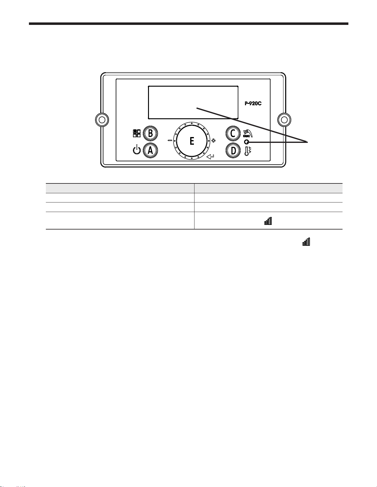
Page 62
5.11 Error Mode
Indicate Example
Error ‘ Er : ’ will ash Er:11
Error Code Er:11
Flashing
Display and Controller are communicating
NOTE: When communication between the Control Display and the main controller is lost, the
will not be displayed.
Page 63

The FT Series Wall Mounted, Combination Boiler
SECTION 6 Error Codes
6.1 Error Code Tables
Page 63
Error
Code
10
11
16
20
28
32
33
Error Code Description
Flame has Extin-
guished 8 (Eight)
Times
Ignition has Failed 10
(Ten) Times
Operating Temperature
Sensor detects Water
Temperature Greater
than 203°F (95°C)
Condensate – Closed
is Normal, Open is
Fault (Condensate
Drain Trap)
Overheat Sensor Open
or Short
DHW Sensor Open or
Short
CH Temperature Sen-
sor Open or Short
Possible Remedies
Press the Power button to clear the Error Code.
If Error happens again:
1. Monitor the gas pressure to the appliance while in operation. Ensure pressure is be-
tween 3.5” to 10.5” WC (Nat. Gas) and 8” to 13” WC (Propane).
2. Check gas valve wire. Ensure connection is secure.
3. Check ame detection sensor. Ensure connections are secure. Normal operating set-
tings are more than 2.5DC before ignition, less than 2.5DC after ignition.
4. Check vent terminations. Ensure there are no blockages.
5. Assure that the ame is stable when lit.
6. If the problem persists, replace the main control.
Press the Power button to clear the Error Code.
If Error happens again:
1. Monitor the gas pressure to the appliance while in operation. Ensure pressure is be-
tween 3.5” to 10.5” WC (Nat. Gas) and 8” to 13” WC (Propane).
2. Check gas valve wire. Ensure connection is secure.
3. Check ame detection sensor. Ensure connections are secure. Normal operating set-
tings are more than 2.5DC before ignition, less than 2.5DC after ignition.
4. Check igniter transformer for proper connection.
5. Clean the spark igniter with steel wool to remove oxides. Ensure proper separation (3-4 mm).
6. Replace the spark igniter if damaged.
7. Assure that the ame is stable when lit.
8. If the problem persists, replace the main control.
Press the Power button to clear the Error Code.
If Error happens again:
1. Check if dip switch Max Fire setting is ON. Switches 6 and 7 should be OFF for normal
operation.
2. Check if CH inlet pipe is blocked. Ensure there is enough water owing to the appli-
ance.
3. Check Operating Temperature sensor at CH heat exchanger outlet. If resistance is
zero, replace the sensor.
4. If the problem persists, replace the main control
Press the Power button to clear the Error Code.
1. Check Condensate and main controller connections. Ensure all are secure.
2. Check Condensate sensor resistance. If resistance is zero, replace the switch.
3. Check Condensate hose. Ensure it is connected and in good condition.
4. Check condensate line and termination for blockages.
5. Check Vent Pipe for blockages.
6. If the problem persists, replace the main control.
This Error Code will go away when CH temperature decreases.
If Error happens again:
1. Check overheat temperature sensor. Ensure connections are secure.
2. Check overheat sensor resistance. If resistance is zero, replace the sensor.
3. If the problem persists, replace the main control.
This Error Code will go away when outlet DHW temperature decreases.
If Error happens again:
1. Check DHW outlet temperature sensor. Ensure connections are secure.
2. Check sensor resistance. If resistance is zero, replace the sensor.
3. If the problem persists, replace the main control.
This Error Code will go away when CH temperature decreases.
If Error happens again:
1. Check CH temperature sensor. Ensure connections are secure.
2. Check CH sensor resistance. If resistance is zero, replace the sensor.
3. If the problem persists, replace the main control.
Recover
methods
Hard
Lock
Hard
Lock
Hard
Lock
Hard
Lock
Soft Lock
Soft Lock
Soft Lock
Page 64

Page 64
Error
Code
35
36 Abnormal Supply Voltage
37 Abnormal Supply Frequency
38
40
41
42
43 Burner Overheat Switch Open
44
45
61
Error Code Description Possible Remedies
Venting (Exhaust) Sensor
Open or Short
Error Appears When Control
Stores Data, but Data is not
Saved
Gas Leakage is Detected for
Greater than 5 seconds, or
three times within 10 minutes
Fan Speed too High with
Flame On
LWCO Jumper
disconnected
Air Pressure Sensor (APS)
Fault
Air Pressure Sensor (APS)
Open
Fan Speed Feedback Signal
Abnormal
This Error Code will go away when exhaust temperature decreases.
If Error happens again:
1. Check Venting (exhaust) temperature sensor. Ensure connections are secure.
2. Check sensor resistance. If resistance is zero, replace the sensor.
3. Check vent pipes for blockage.
4. If the problem persists, replace the main control
Supply voltage is too low to operate. This Error Code will go away when supply
voltage returns to normal operating range.
If Error happens again:
1. Ensure appliance is properly wired to a power source meeting the requirements
on the rating plate.
2. If problem persists, replace the main control
Supply frequency is too high to operate. This Error Code will go away when supply
frequency returns to normal operating range.
If Error happens again:
1. Ensure appliance is properly wired to a power source meeting the requirements
on the rating plate.
2. If problem persists, replace the main control.
Press the Power button to clear the Error Code.
Replace the main control.
IMPORTANT: If you smell gas, STOP! Follow the instructions on page 2, this
manual, and call a qualied service technician or the fuel gas utility.
Press the Power button to clear the Error Code.
If Error happens again:
1. Check the appliance cover. Ensure it is secure.
2. Check gas connections for leakage with a soapy solution. Fix any leaks.
3. Check condition of the burner assembly.
4. If the problem persists, replace the main control.
Press the Power button to clear the Error Code.
If Error happens again:
1. Check the vent connections for blockages.
2. Check the burner assembly.
3. Check fan operation. If fan appears to be operating normally but RPMs are too
high, replace the fan.
4. If the problem persists, replace the main control.
Press the Power button to clear the Error Code.
If Error happens again:
1. Ensure the LWCO jumper wire is properly connected.
2. If the problem persists, replace the main control.
Press the Power button to clear the Error Code.
If Error happens again:
1. Check burner overheat switch connections. Ensure connections are secure.
2. Check switch resistance. If resistance is zero, replace the switch.
3. If the problem persists, replace the main control.
Press the power button to reset
If error happens again:
1. Check the vent pipe for blockages.
2. Check the vent pipe for blockages.
3. If error do not clear, replace the APS
4. If the problem persists, replace the main control.
Check the aps connection.
1.If APS is closed and connections are secure, check APS connection.
2. If the problem is not happen, replace the APS
3. If the problem persists, replace the main control.
This Error Code will go away when the condition is remedied.
If Error happens again:
1. Check the connections to the fan. Ensure all are secure.
2. If the fan does not rotate during the ignition sequence, check for AC8V~26.5V power
at the fan connection. If AC8V~26.5V power is present at the control, replace the
fan. If the blower does not have AC8V~26.5V power, check power at the control. If
AC8V~26.5V power is not present at the control, replace the control.
3. If the problem persists, replace the main control.
Recover
methods
Soft Lock
Soft Lock
Soft Lock
Hard Lock
Hard Lock
Hard Lock
Soft Lock
Hard Lock
Hard Lock
Soft Lock
Soft Lock
Page 65

The FT Series Wall Mounted, Combination Boiler
SECTION 6. Error Codes (continued)
Page 65
Error
Code
66
68
70
72
76 Poor Communication
80
81 Low Water Level Circuit
85
94
Error Code Description Possible Remedies
Mixing Valve Initial Value
Error
(Mixing Valve Cannot Return
to Initial Position)
Mixing Valve Operation Error
(Mixing Valve Stuck in Initial
Position)
Register, Ram, Rom, I/O
Port, AD Abnormal, Important
EPROM Data or Safe Data
Abnormal
Flame Signal Detected before
Ignition
Low Water Level Sensor
(Low Water Level Detected
Four (4) Consecutive times)
Freeze Protection
(Appliance has detected
water temperature below
34°F(1°C)
Exhaust Sensor detects Vent
Temperature is Greater than
190oF (88oC)
This Error Code will go away when the condition is remedied.
If Error happens again:
1. Turn power OFF and ON at the main power switch internal to the appliance.
2. Check wiring connections to mixing valve. Ensure all are secure.
3. Replace mixing valve.
4. If the problem persists, replace the main control.
This Error Code will go away when the condition is remedied.
If Error happens again:
1. Turn power OFF and ON at the main power switch internal to the appliance.
2. Check wiring connections to mixing valve. Ensure all are secure.
3. Replace mixing valve.
4. If the problem persists, replace the main control.
This Error Code will go away when the condition is remedied.
If Error happens again:
1. Turn power OFF and ON at the main power switch internal to the appliance.
2. If the problem persists, replace the main control.
This Error Code will go away when the condition is remedied.
If Error happens again:
1. Check the appliance cover. Ensure it is secure. Flame detection sensor can detect an
external light source.
2. Check ame detection sensor. Ensure connections are secure. Normal operating
settings are more than 2.5DC before ignition, less than 2.5DC after ignition.
3. If the problem persists, replace the main control.
This Error Code will go away when the condition is remedied.
If Error happens again:
1. Check connections from main control to display panel.
2. If the problem persists, replace the display and/or the main control.
This Error Code will go away when the condition is remedied.
If Error happens again:
1. Ensure all valves are open to the appliance and there are no leaks.
2. Ensure all air has been purged from the system.
3. Check wiring connections to low water level sensor. Ensure all are secure.
4. Check low water level sensor resistance. If resistance is zero, replace the sensor.
5. If the problem persists, replace the main control.
This Error Code will go away when the condition is remedied.
If Error happens again:
1. Ensure all valves are open to the appliance and there are no leaks.
2. Check wiring connections to low water level sensor. Ensure all are secure.
3. Check low water level sensor resistance. If resistance is zero, replace the sensor.
4. If the problem persists, replace the main control.
This Error Code will go away when the freezing condition is remedied.
If Error happens again:
1. Ensure appliance is located in a mechanical room protected from freezing conditions.
2. Ensure all valves are open to the appliance, there are no leaks.
2. Check wiring connections to low water level sensor. Ensure all are secure.
3. Check low water level sensor resistance. If resistance is zero, replace the sensor.
4. If the problem persists, replace the main control.
This Error Code will go away when the condition is remedied.
If Error happens again:
1. Check if dip switch Max Fire setting is ON. Switches 6 and 7 should be OFF for normal
operation.
2. Check exhaust temperature sensor. Ensure connections are secure.
3. Check sensor resistance. If resistance is zero, replace the sensor.
4. Check exhaust vent for blockage.
5. If the problem persists, replace the control.
6. If the problem persists, replace the heat exchanger.
Recover
methods
Soft Lock
Soft Lock
Soft Lock
Soft Lock
Soft Lock
Soft Lock
Soft Lock
Soft Lock
Soft Lock
Page 66
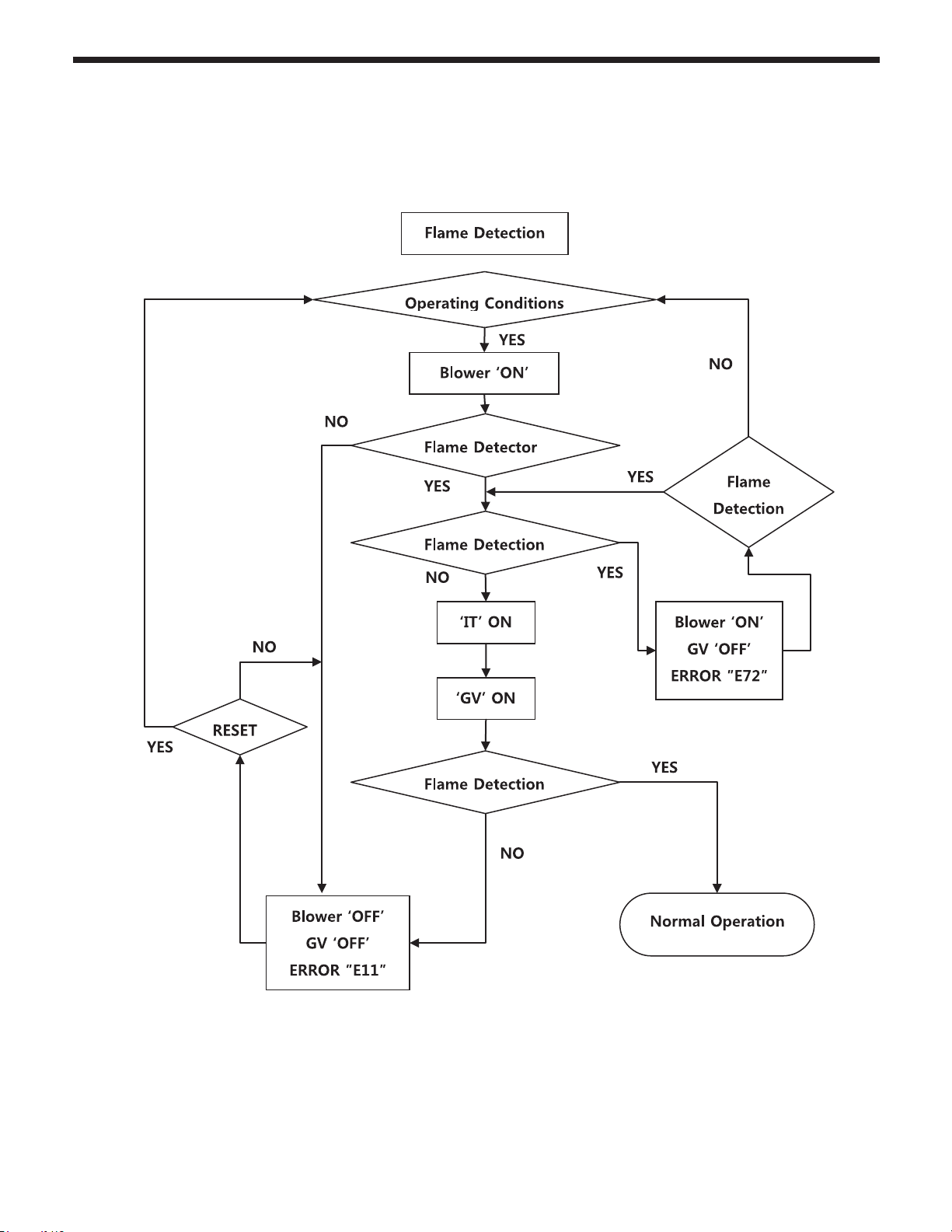
Page 66
6.2 Fault Tree Analysis
1. Flame detection
Page 67
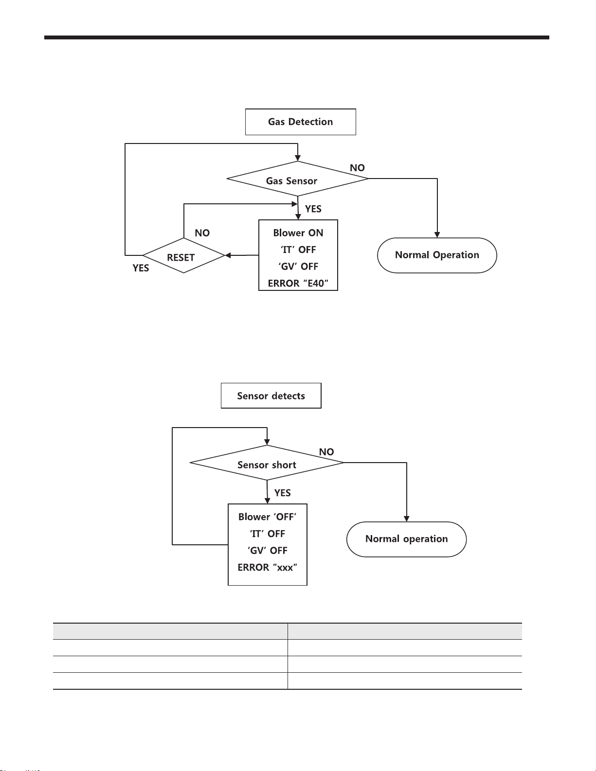
The FT Series Wall Mounted, Combination Boiler
6.2 Fault Tree Analysis (cont)
2. Gas Detection
Page 67
3. ‘Storage’, ‘DHW’, ‘OP’, ‘CH overheat’, ‘Exhaust heat’ Sensor detects
Error code contents
E32 DHW NTC open or short
E33 OP NTC open or short
E35 Exhaust NTC open or short
Page 68
Page 68
SECTION 7 Trouble Shooting
7.1 Diagnostics
Question Answer
Make sure that the ON/OFF button on the Control Panel has been turned ON.
If the monitor on the Control Panel is blank, make sure the power cord is
Burner does not ignite
when the hot water is
opened.
plugged and 4A fuses on the main controller in the units are good.
Make sure that there is water supplied to the unit. The unit activates once
the inlet water ow is over 0 gpm.
Make sure the cold and hot water lines are not plumbed in reverse side.
Make sure that the cold water and gas supply lines are opened.
Make sure that the water lines are not frozen.
Check that the setting temperature on the unit is not too low
Make sure that the lter in the cold water supply line is not clogged with debris.
Water is not hot enough.
Water is too hot.
Hot water temperature
uctuates at the opened
tap.
The blower is still oper-
ating after the combus-
tion stops.
Temperature Rise
too Quickly
Abnormal sounds come
from unit during opera-
tion.
Heater doesn’t re when
DHW ow is initiated
CH Temp drops lower
than expected before unit
re-res
Make sure that the gas supply type is correct.
Check the supply and manifold gas pressures are in accordance with specications.
Make sure that the water ow sensor with three wires has been properly
connected on the top of heat exchanger.
Make sure that the setting temperature on the unit is not too hot.
Make sure that the lter in the cold water supply line is not clogged with debris.
Make sure that the gas supply type is correct.
Make sure that the lter in the cold water supply line is clean.
Make sure that the gas supply type is correct.
Check the supply gas pressure is sucient.
This is normal because the blower keeps operating for 1 minute to vent
(exhaust) the ue gas from the chamber once the combustion has stopped.
Occurs when supply water temperature in heat exchanger rises faster than
2°F per second during the rst two minutes the burner is on. Automatically
resets after a few minute delay or using manual reset on control panel. See
message displayed TEMPERATURE SENSOR and follow procedure for
loose connections.
A leak of combustion gas between sealed chamber and exhaust tube inside
the unit. Call a qualied service technician for evaluation.
Improper venting termination, make sure that the venting termination com-
plies with specication.
Check the supply gas pressure is sucient. Insucient gas pressure will
cause unstable burner ame and noise.
Potentially the domestic water ow is too low. Min allowable is 0.75 gpm.
Check in Manual Mode OTO AGA
Change Parameter 14:bo to 10degrees F (5.5 degrees C)
Page 69
The FT Series Wall Mounted, Combination Boiler
Page 69
7.2 Suggested Corrective Actions
This controller is able to record information about the boiler’s condition at the time of the ve previous faults or
errors. Refer to the Section ‘5.10 Error Mode’ of this manual.
Display Condition Diagnostic Corrective Action(s)
Nothing shown
on display
control panel and
blower running at
full speed.
Nothing is shown
in display control
panel and no
other boiler
components are
operating.
Control is not
receiving power.
Control is not
receiving 120V power.
Check wiring for short
circuit or incorrect
wiring.
Check transformer
connection to the
control per wiring
diagram. Check
for 12V output of
transformer.
Check service switch
and/or circuit breaker
to boiler turned is on.
Is there 120 Volts at
the service switch?
Is the ON/OFF
POWER
SWITCH (inside boiler
case) turned on?
Check for 120 volts
at the line voltage
terminal block located
inside the boiler case.
Correct wiring per wiring diagram
including connection of transformer to
the control.
Replace transformer if it is receiving
120V, but not outputting 12Vac.
Turn on service switch to power boiler.
Troubleshoot and correct the power
supply to the manual switch.
Turn ON the manual power switch
inside the boiler case.
Correct wiring inside the boiler case
using the wiring diagram in this
manual.
Nothing is shown
on control panel,
but boiler is
operating.
Occurs when the
communication is lost
from the control to the
display.
Inspect the fuse.
Replace if necessary.
Check for loose
connections and
proper pin alignment/
engagement on the
Control's plug.
Cycle power o and
on using boiler power
switch and check for
operation.
Replace the fuse with proper part
found in the replacement part section
of this manual. If fuse blows again
recheck wiring per diagram.
Check for continuity on the wire
harness from the display to the control.
See repair parts section for proper
replacement part.
Replace with new display module.
See repair parts section for proper
replacement part.
Page 70

Page 70
Fault Condition Diagnostic Corrective Action(s)
Check all the temperature readings
of the boiler on the DIAGNOSTICS -
TEMPERATURE
SENSOR
FLAME FAULT
BLOWER FAULT
IGNITION
FAULT
Occurs when
a temperature
sensor has
electrically
shorted
(SHORT) or has
become
disconnected
(OPEN).
Occurs when
ame is
detected when
there should be
no ame.
Blower unable to
reach required
speed or does
not reach 0
RPM when
turned o.
Even if boiler
went through
8 ignitron
attempts, but
cannot detect
ame
Reset using manual
reset screen on control
panel. (Power button)
Reset using manual
reset screen on control
panel.
(Power button)
Reset using manual
reset screen on control
panel.
(Power button)
Power o and on.
TEMPERATURES menu to determine
if any sensors are currently displayed
as SHORT or OPEN.
Check wire harness for loose
connections and pin engagement
at sensor Connection and Control
module.
If problem persists after checking items
above replace Control. Refer to repair
parts section for kit number.
Burner may be operating too hot due
to incorrect combustion. Inspect ame
and conduct combustion test.
Check for ame at burner via ame
current with burner o. Turn boiler o
and watch ame through observation
port. If ame continues after shutdown
replace gas valve.
Check wire harness for loose
connections and pin engagement at
blower.
Connections.
Boiler in standby mode and blower not
running. If BLOWER SPEED is not 0
RPM then replace blower.
If blower does not rotate during ignition
sequence check for 120V power at
blower connection. If 120Vac power
at blower motor and it doesn't start
replace blower. Check power at
Control. If 120Vac is not present at
Control when boiler is powered replace
Control.
Dirty burner and/or heat exchanger will
cause high back pressure and poor
ignition.
Visual inspection of ue ways often will
not be able to diagnose condition.
Check incoming gas pressure with
boiler o and at Max re. Adjust within
limits on rating label.
Check for ue pipe and intake pipe
restrictions or blockage
GAS VALVE
FAULT
The Control
has detected a
problem with it
gas valve
output circuit.
Reset using manual
reset screen on control
panel.
(Power button)
Check burner fasteners and gaskets
Check air intake pipe and proper
propane orice
Check wire harness connections
between gas valve and Control.
If lockout re-occurs replace Control.
Page 71

The FT Series Wall Mounted, Combination Boiler
SECTION 8 Maintenance
Page 71
8.1 Annual startup & general maintenance
Regular Maintenance
- This Manual should be placed in a safe and dry
location near the Combination boiler. Maintenance
instructions should be carried out by the following
guidelines.
Maintenance procedures [ Daily ]
- Check that the boiler casing is closed.
Check if there is any problem with the Combination
boiler casing and the two upper and lower screws
are tightened well. Combination boiler casing must
be closed while it is running.
WARNING
To prevent potential severe personal injury,
death or substantial property damage,
remove all contaminated materials.
If contaminants are found:
Remove products immediately from the area.
In order to check the status of Combination
boiler, call a qualied service technician to
inspect the combination boiler for possible
damage from acid corrosion.
WARNING
- Check the power source.
Make sure that the power cord is correctly
connected. The main power line is connected to
the manual switch box inside a combination boiler.
(Power line through the strain relief in the bottom of
the combination boiler casing and x it.)
- Check the status of the control panel
Check status of the power supply. Please check for
any debris on the button.
Maintenance procedures [ Monthly ]
- Check the vent pipe.
Visually inspect the ue gas vent piping for detecting
any signs of blockage, leakage or deterioration
of the piping. Please contact a qualied service
technician immediately if you nd any problem.
- Check the air inlet pipe.
Visually inspect the air inlet to be sure it is
unobstructed. Inspect entire length of air piping
for ensuring that piping is intact and all joints
are properly sealed. Call your qualied service
technician if you notice any problems.
- Check the relief valve.
Inspect the Combination boiler relief valve and
the relief valve discharge pipe for any signs
of weeping or leakage. If the relief valve often
weeps, immediately contact your qualied service
technician for inspecting the Combination boiler and
system.
DO NOT store combustible materials, gasoline
or any other ammable vapors or liquids near
the water heater. Remove them immediately or
store them other places.
- Check the condensate outlet.
While the Combination boiler is running, check the
discharge end of the condensate drain tubing.
Make sure that no ue gas is escaping from the
condensate drain tubing.
If ue gas is continuously escaping, it is a serious
problem. Call your qualied service technician for
inspecting the Combination boiler and condensate
line. Also, rell the condensate trap if problem
persists regularly.
- Check the vent terminal screen vent (rodent
screen).
If you encounter a problem of combustion
specications, visually inspect the terminal screen.
And then replace it with spare parts or clean the
screens.
Page 72

Page 72
- Check the air vent
If the air vent valve seems to work freely without
leaking, replace cap “A” by twisting all the way on.
Loosen cap “A” one turn to allow vent to operate.
If vent does not operate correctly, replace the vent.
A
A
Maintenance procedures [Every 6 Months]
seat. If the valve continues to weep, contact your
qualied service technician for inspecting the valve
and system. If water does not ow from the valve
even though you have lifted the lever completely, the
valve or discharge line may be blocked. Shut down
the Combination boiler immediately. Call your qualied
service technician to inspect the combination boiler
and system.
- Check the burner state
You can clean the exterior of burner. However, if you
need to clean the inside of the burner stage, you should
call a qualied service technician.
- Check the boiler piping (gas and water)
Visually inspect for leaks around internal water
piping. Also inspect external water piping,
circulators, relief valve and ttings. Immediately
call a qualied service technician to repair any
leaks. Leaks must be xed by a qualied service
technician immediately.
Failure to comply with this instruction could result in
severe personal injury, death or substantial property
damage.
- Check the pressure relief valve
WARNING
Leaks must be xed by a qualied service technician
immediately. Failure to comply with this instruction
could result in severe personal injury, death or sub-
stantial property damage. This discharge line must
be installed by a qualied heating
installer or a service technician.
Before proceeding, verify that relief valve outlet has
been piped to a safe place of discharge, avoiding
any possibility of scalding from hot water. If water
ows freely, release the lever and allow the valve
to seat. Watch the end of the relief valve discharge
pipe to ensure that the valve does not weep after
the line has had time to drain. If the valve weeps,
lift the seat again to attempt to clean the valve
Page 73

The FT Series Wall Mounted, Combination Boiler
8.2 Flushing the Combination Boiler
Flushing the Heat Exchanger is a complicated procedure that should only be done by an authorized technician or
licensed professional. Keep in mind that improper maintenance can void your warranty.
1. Disconnect electric power to the combination boiler.
2. Close the shuto valves on both hot water outlet
and cold water inlet lines. (V1 & V2)
3. Connect hose “D1” to the valve “V3” and place the
free end in the bucket. Connect hose “D3” to the
circulation pump outlet and the cold water inlet
V3
V1
V4
V2
line at the valve “V4”. Connect hose “D2” to the
circulation pump inlet and place the free end in the
bucket.
Page 73
4. Pour the cleaning solution into the bucket. Place the drain hose
(D1) and the hose (D2) to the pump inlet into the cleaning solution.
5. Open service valves (V3 & V4) on the hot water outlet and cold
water inlet lines.
6. Turn on the circulation pump (Operate the pump and allow the
cleaning solution to circulate through the combination boiler for at
least 1 hour at a rate of 4 gallons per minute.)
7. Rinse the cleaning solution from the combination boiler
as follows:
- Remove the free end of the drain hose (D1) from the
bucket.
- Close service valve, (V4), and open shut o valve,
(V2).
Do not open shut o valve, (V1).
- Allow water to ow through the combination boiler for
5 minutes.
- Close shut o valve (V2).
8. Ensure service valves are closed (V3 and V4) and shut o
valves are open (V1 and V2).
D1
D2
D3
9. Disconnect all hoses.
10. Remove the cold water inlet lter from the combination boiler and clean out any residues.
11. Reinsert the lter and ensure the lter cap is securely tightened.
12. Connect electrical power to the combination boiler.
Page 74
Page 74
8.3 Draining and Cleaning
Flow Restrictor
DHW Cold Water
Inlet Filter
CH Return Filter
FTCW140
1. Place a bucket under the appliance to collect the residual water inside the combination boiler.
2. Press the Power button on the front control panel to turn OFF the electrical power to the combination boiler.
3. Turn o the gas valve.
4. Close water supply valve on the inlet to the appliance. If there is no valve, turn o main water valve.
5. Open the hot water faucets completely.
6. Remove the CH (Central Heat) return lter by removing the metal pin and then pulling
the lter downward.
7. Remove the Cold Water Inlet lter by removing the two small pins and then pulling the
lter downward at an angle. If your system is using a ow restrictor, be sure that the
ow restrictor is also cleaned and placed back into the system during re-assembly.
8. Clean them with a toothbrush and clean running water.
9. To rell the combination boiler, reassemble the lters back into the combination boiler and
reverse steps 7 back to 1.
CH Return Filter
FTCW199
DHW Cold Water
Inlet Filter
8.4 Freeze Protection
FT Series Boilers are certied for indoor use only, and
are not design-certied for placement outdoors.
Proper precautions for freeze protection are
recommended for boiler installations in areas where
the danger of freezing exists.
Power outage, interruption of gas supply, failure of
system components, activation of safety devices, etc.,
may prevent a boiler from ring. Any time a boiler
is subjected to freezing conditions, and the boiler
is not able to re, and/or the water is not able to
circulate, there is a risk of freezing in the boiler
or in the pipes in the system. When water freezes,
it expands which may result in bursting of pipes, or
damage to the boiler, which could result in leaking or
ooding conditions.
Dierent glycol products may provide varying
degrees of protection. Glycol products must be
maintained properly in a heating system, or they may
become ineective. Consult the glycol specications,
or the glycol manufacturer, for information about
specic products, maintenance of solutions, and set
up according to your particular conditions.
Not all pumps are capable of maintaining the
reduced temperature rise required with glycol
concentrations greater than 35%.
NOTICE
NOTICE
Page 75
The FT Series Wall Mounted, Combination Boiler
Page 75
Freeze Protection (continued)
WARNING
Do NOT use automotive antifreeze or ethylene
glycol. Use only inhibited propylene glycol solutions
which are specially formulated for hydronic
systems. Ethylene glycol is toxic and can attack
gaskets, seals, and metallic components used in
hydronic systems. A correct glycol concentration
and inhibitor level is critical.
Some items to consider are
• Consider the eects of reduced heat transfer and
an increase in head pressure against the system
circulator. For example: A 30% mixture of glycol will
result in a BTU output loss of 15% with a 5% increase
in head against the system circulator.
• Glycol mixtures should not exceed 50%. A 50%
mixture of glycol will result in a BTU output loss of
30% with a 50% increase in head against the system
circulator.
SECTION 9 Installation Check
9.1 Quick View
Before Installing
- Make sure that there is enough space for installing
Water and gas line.
Verify vent/air termination is located as required.
- All models need for propane Conversion which
requires a separate gas conversion manual.
Install Water Piping
- Boiler loop piping must be sized to the minimums
listed in the Boiler manual. Using smaller piping will
cause performance problems.(page 34)
Install Vent & Air Piping
- Slide the air inlet pipe and vent pipe into the Boiler
pipe connector.
- Make sure the terminations are placed as required
in the manual and that air intakes are at least 12
inches above normal snow line.
- Refer to the material check list in this guide for a list
of items needed.
• The glycol solution should be tested as recommended
by the glycol manufacturer but not less than annually.
Some items of concern are pH additive breakdown,
inhibitor reduction, etc.
• Glycol/antifreeze solutions expand more than water;
therefore, system design must take this into account.
For example: a 50% by volume solution expands
4.8% in volume for a temperature increase from 32◦F
to 180◦F, while water expands 3% over the same
temperature rise.
CAUTION
It is highly recommended to follow the manufacturers
recommended concentrations, expansion requirements,
and maintenance recommendations. You must carefully
calculate the additional friction loss in the system as
well as the reduction in the heat transfer coecients.
__________________________________________
Install Condensate Piping / Tubing & Components
- Fill out the material check list in this guide to
ensure you have the tubing or PVC pipe and all
components needed for the condensate piping.
- Connect internal components that are supplied with
the Boiler.
Install Gas Piping
- Install a union and shuto valve.
Wire the Boiler
- Connect power wiring and control wiring per boiler
manual wiring diagram.(Section 4.19)
Start up, Adjust & Test
- Follow the Boiler manual instructions to clean
the system if needed, then ll and check water
chemistry.
Page 76
Page 76
9.2 Final Check Lists
Final check : Installation Conditions.
• Is the Boiler properly mounted on the wall?
• Is there space for a drain which is close to the
Boiler?
• Are there any combustible materials near the Boiler
and vent pipe?
• Is the air supply sucient for proper operation of
the Boiler?
• Are the proper service clearances maintained?
• Is the distance between the Boiler and point of vent
termination minimized?
• Is the proper distance from windows, doors, and
other intake vents maintained?
Final check : Gas pipe installation
• Is the gas supply line equipped with a manual shut
o valve?
• Is the gas supply line a minimum of 3/4˝ inner
diameter?
• Is the gas supply line length and diameter adequate
to deliver the required BTU’s?
• Has the gas supply line pressure been measured?
• Does the supply gas type match the type indicated
on the boiler rating plate?
Final check : Connecting the power supply
• Please check that the power is 120V AC.
• Have you checked the polarity of the electrical
connection?
Final check : Pressure relief valve
• Have you properly installed an approved pressure
relief valve on the boiler?
• If applicable, has the DHW pressure relief valve
been properly installed. This will be dependent on
local codes.
Final check : Burner ames
• The burner ame must be checked periodically for a
constant proper blue color.
• If the ame does not appear normal, the burner may
need to be cleaned.
• If the burner needs to be cleaned, it must be
performed by a qualied service technician.
Final check: Air/Vent pipe installation
• Has the Boiler been vented with 3˝ or 2” PVC,
CPVC, Polypropylene or BH Special
Gas Vent (S636 PVC, CPVC) for Category IV
appliances in accordance with this manual and/or
your local code?
• Is the vent termination at least 12˝ above the
exterior grade?
• Is the total vent length within the maximum vent
length restriction?
• Have you checked the air/vent piping for leaks?
• Have you properly supported the vent termination?
• Are all vent runs properly supported?
• Is the vent sloped upward toward the vent
termination at a rate of 1/4˝ per foot (2% grade)?
Final check : Condensate drain installation
• Have you installed a condensate drain line from the
Boiler to a drain or laundry tub?
Final check : Setting the DIP switches
• Are all DIP switches correctly set on the main board?
Sight Glass
Blue ame
Page 77

The FT Series Wall Mounted, Combination Boiler
This page intentionally left blank.
Page 77
Page 78

Page 78
Casing _ Feature
SECTION 10 Parts List and Illustrations
FTCW140
FT1894 Mounting Bracket
LAARS Heating Systems
Page 79

The FT Series Wall Mounted, Combination Boiler
KRB
Code
Price
O
S552200045
Exhaust vent duct Assembly
H190200003
S453100002
S552100064
S549100119
H850150049
S552200070
S549100121
S552200069
Air inlet
H190200002
S549100120
S529100025
Air vent
S322100020
Air vent rubber packing
S551100045
Gasket bracket
H140320030
Safety valve rubber pad
S551100063
Air pressure sensor (80)
S264100067
PCB
S115900025
Ignition transformer
S223100036
Control
H850150051
Display Control (P
S121110029
Bracket
H120900014
Condensate blockage,
S264100062
Control bracket
H120900013
Power switch
S264100057
Terminal block (10P)
S900140007
Front cover
H110130132
Control
H850150050
Pressure gauge
S325100028
S555100029
Wall
H140120024
Casing Assembly
H110330070
Wall Mount bracket (bottom)
H120900017
Page 79
No. Description
O-7
-Ring P7 FT1601
15
15-1
15-2
15-3
15-4
15-5
15-6
15-7
16
16-1
16-2
Stainless band (Ø100)
Packing
Exhaust vent duct
Exhaust testing cap
O-Ring P85
Exhaust vent adaptor (Inside)
O-Ring P75
duct Assembly FT1010
Air inlet duct
Air inlet adaptor (Inside)
17
18
19
20
21
22
Control (NGTX -900CP) FT1899
23
24
25
sub-bracket FT1954
-920C) FT1620
26
27
Air press switch FT1022
28
29
30
31
32
display cover / window FT1024
33
34
35
Intake/Exhaust sealing pad
Mount bracket (top) FT1924
36
37
Part
Number
FT1002
FT1603
FT1604
FT1611
FT1606
FT1607
FT1608
FT1609
FT1605
FT1612
FT1321
FT1013
FT1797
FT1921
FT1804
ST1006
FT1511
FT1922
FT1020
FT1021
FT1923
FT1025
FT1771
N / A
FT1936
Page 80

Page 80
Description
Initials Date
Status
Kiturami Fire Tube Drawing Number List
CH Block & DHW Block Ass’y_ Feature
LAARS Heating Systems
FTCW140
0-22A
0-22A
0-22A
0-22A
0-22A
0-22A
DHW Assembly
CH Assembly
Page 81

The FT Series Wall Mounted, Combination Boiler
KRB
Code
Price
H199990175
S551200033
S551200034
S551200035
S551200036
S551100004
S551100005
S455100095
S455100096
S549100141
S549100140
S455100074
S514100106
S549100142
S455100106
S419100040
S311200030
S549100155
S419100039
H160320029
KRB
Code
Price
H199990176
S551200027
S551200028
S551200029
S551200033
S551200035
S551100046
S455100069
S455100095
S419100042
S549100147
S514100107
S311200029
S419100041
S317100009
S193000001
S549100146
S549100143
S549100149
S549100145
S549100141
S514100105
CH Assembly
Page 81
No. Description
B2
O-20
O-22
O-22A
O-25
P-5
P-6
13
14
53
54
55
56
57
58
59
60
61
62
63
CH Hydro block Assembly FT1100
O-Ring P20
O-Ring P22
O-Ring P22A
O-Ring P25
3/4" Packing
1" Packing
Piping clip FT1107
Pump clip FT1108
Block cap FT1121
Return block FT1523
R Clip FT1524
CH Return, Supply connector FT1215
CH Filter FT1216
U Clip FT1217
CH Return pipe FT1218
CH Return sensor FT1219
3-way valve FT1220
CH Supply pipe FT1527
Pump FT1222
Part
Number
FT1513
FT1644
FT1515
FT1516
FT1646
FT1691
DHW Assembly
No. Description
B3 DHW Hydro block Assembly FT1200
O-15 O-Ring P15 FT1685
O-16 O-Ring P16 FT1643
O-18 O-Ring P18 FT1687
O-20 O-Ring P20 FT1513
O-22A O-Ring P22A FT1515
P-4 1/2" Packing FT1645
12 Flow sensor cl i p FT1208
13 Piping clip FT1107
40
41
42
43
44
45
46
47
48
49
50
51
52
DHW Outlet pipe FT1109
DHW Outer block FT1518
DHW Nipple FT1111
DHW Temperature sensor FT1112
DHW Inlet pipe FT1114
Flow sensor FT1115
Mixing valve FT1116
DHW Inlet block FT1522
DHW Filter body FT1549
Flow restrictor (12L) FT1119
DHW Filter mesh FT1120
Block cap FT1121
DHW Connector FT1122
Part
Number
Page 82
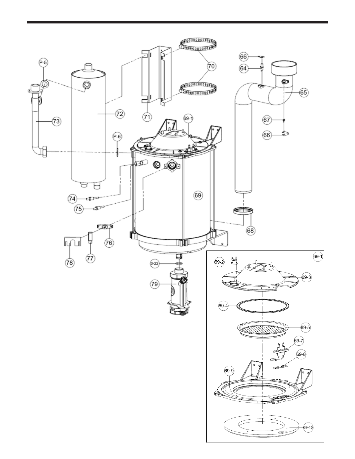
Page 82
Heat Exchanger & Tank _ Feature
LAARS Heating Systems
FTCW140
Heat Exchanger & Tank
Page 83

Mascot FT Combination Boiler
KRB
Code
Price
S551200034
S551100004
S551100005
S549100223
S549100148
H140240002
S311200027
S552100054
H120240461
H130120301
S311400021
H870060125
S551100083
H130210023
S333100033
S554200007
H870060126
S562200107
S453100015
H120900012
H120420007
S419100038
S311200026
S312100011
H850130001
S314200007
H140240003
H160520005
FTCW140
Heat Exchanger & Tank
Page 83
No. Description
O-22 O-Ring P22 FT1644
P-5 3/4" Packing FT1646
P-6 1" Packing FT1691
64
65
66 Exhaust sensor bracket FT1529
67 Exhaust overheat sensor FT1307
68 Exhaust pipe packing (lower) FT1666
69 Heat Exchanger Assembly FT1313
69-1 Burner Assembly FT1925
69-2
69-3 Burner upper case FT1926
69-4 Burner packing FT1927
69-5 Burner FT1314
69-7 Ignition rod FT1315
69-8 Ignition rod gasket FT1316
69-9 Burner downside case FT1928
69-10 Refractory FT1665
70 Stainless band (Ø150) FT1528
71 DHW Tank bracket FT1530
72 DHW Tank FT1323
73 CH Supply upper pipe FT1322
74 Temperature sensor FT1324
75 Low level sensor FT1325
76 Flame detector sensor bracket FT1669
77 Flame detector sensor FT1327
78 Flame detector sensor cover FT1069
79 Condensate trap Assembly
EX-Adaptor
Exhaust pipe
Overheat sensor FT1310
Part
Number
FT1784
FT1067
FT1783
Page 84

Page 84
Fan & Gas Valve _ Feature
LAARS Heating Systems
FTCW140
Blower and Gas Valve
Page 85

Mascot FT Combination Boiler
No. Description
Part
Number
KRB
Code
Price
82 Fan guide FT1532 H870060054
83 Fan rubber packing (1.0t) FT1721 S551100047
84 Mash FT1720 H140140003
85 Fan rubber packing (1.6t) FT1082 S551100071
86
Fan Assembly
FT1407
H160510059
86-1 Fan FT1406 S242100047
86-2 Fan sealing O-Ring ST1038 S551200026
86-3 Gas mixer housing FT1409 S549100132
86-4 Intake orifice (140K) FT1535 H160620001
87
Stainless band (Ø60) FT1078 S455100088
88
Air intake hose (120,140K)
FT1533 S421200052
89
Nylon Barb Y Fitting
FT1918
H850150151
90 Nozzle (Natural/140K) FT1412N H130010019
Nozzle (Propane/140K) FT1412P H130010020
91 Gas pipe (upper) FT1536 S412190039
92 Gas valve Assembly FT1413 H160430012
92-1 Gas valve outlet adaptor FT1919 H870060055
92-2 Gas valve O-Ring FT1727 S551200001
92-3 Gas valve FT1416 S172110003
92-4 Gas valve inlet adaptor FT1538 S345100010
92-5 Gas valve bracket FT1539 H120900018
93
1/2" Spiral packing FT1710
S557100001
94 Gas pipe(down) FT1419 S412190040
95 Gas inlet adaptor
FT1893 H870060074
List
No. Description
Part
Number
KRB
Code
Price
100 Pressure Relief Valve FT1500 S323100096
101 Outdoor Temp. Sensor FT1501 S319300014
102 Bird Screen 3" FT1730 S114200020
104 Spare Parts Kit FT1930 H990050017
105 Condensate Hose ST1070 S421200027
106 Restrictor (12L) FT1506 S549100150
107 Wall Hung Bracket FT1894 H140120025
108 Bird Screen 2" FT1508 S114200021
109
Nozzle LNG 7.1 (3,000~10,000ft) FT1931 H130010024
110
Nozzle LNG 5.0 (3,000~6,500ft) FT1932 H130010027
111
Nozzle LNG 5.1 (6,500~10,000ft) FT1933 H130010026
112
Nozzle LNG 6.2 (3,000~10,000ft) FT1934 H130010025
113
Nozzle LNG 4.8 (3,000~10,000ft) FT1935 H130010028
114
Wire Harness FT1903 S274400012
Page 85
Blower and Gas Valve
FTCW140
Optional Items
Page 86
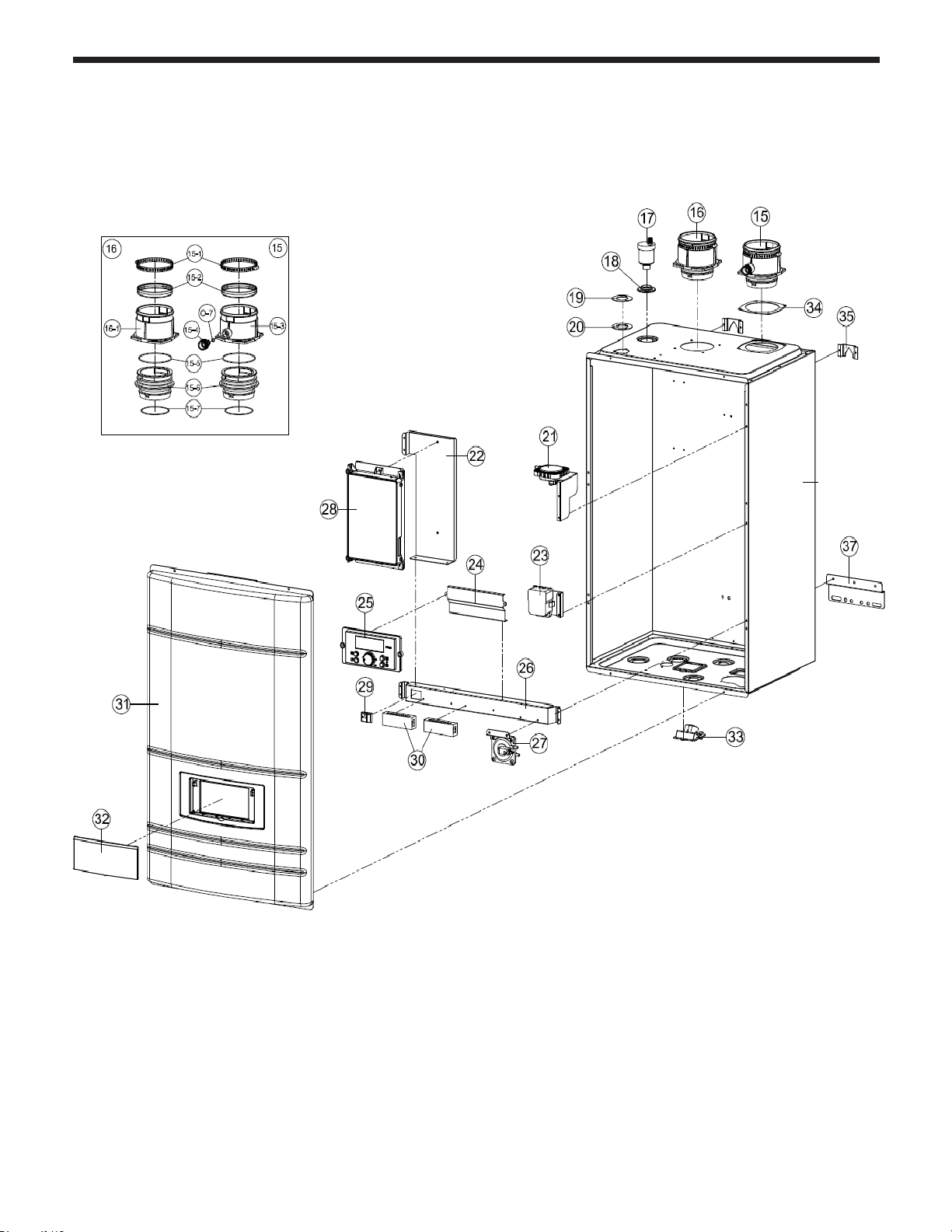
Page 86
Feature
FTCW199
Page 87

The FT Series Wall Mounted, Combination Boiler
Part
NNootteess
O
Air vent rubber packing
Gasket bracket
Safety valve rubber pad
Air
Control bracket
Ignition transformer
Control
Display Control (P
Bracket
Condensate blockage, Air pressure
switch
PCB
R2080604
Power switch
Terminal block (6P)
Front cover
Control
Pressure gauge
Intake/exhaust sealing pad
Wall hung bracket (top)
Wall Mount Bracket
Wall hung bracket (bottom)
FTCW199
Page 87
No. Description
O-7
15
15_1
15_2
15_3
15_4
15_5
15_6
15_7
16
16_1
17
-Ring P7 FT1601
Exhaust vent duct Assembly
Stainless band (Ø100)
Packing
Exhaust vent duct
Exhaust testing cap
O-Ring P85
Exhaust vent adaptor (Inside)
O-Ring P75
Air inlet duct Assembly
Air inlet duct
Air vent
18
19
20
21
pressure sensor (80)
22
23
24
25
sub-bracket
-920C)
26
Number
FT1002
FT1603
FT1604
FT1611
FT1606
FT1607
FT1608
FT1609
FT1909
FT1605
FT1321
FT1013
FT1797
FT1921
FT1804
FT1751
ST1006
FT1752
FT1620
FT1795
27
28
Control (NGTX-900CP) FT1899
29
30
31
32
33
34
35
36
37
FT1022
FT1020
FT1827
FT1920
display cover / window FT1024
FT1025
FT1771
FT1924
FT1894
FT1936
Page 88

Page 88
CH Block & DHW Block Ass’y_ Feature
FTCW199
CH Assembly B2
‘B2’
CH Block
Packing
Sensor
Ass’y
DHW Assembly B3
‘B3’
DHW Block
Ass’y
Page 89

The FT Series Wall Mounted, Combination Boiler
Notes
‘B3’ - DHW Block Ass’y_ List
Notes
FTCW199
CH Assembly B2
No. Description
B2
O-20
O-22
O-22A
O-25
P-5
P-6
13
14
53
54
55
56
57
58
59
60
61
62
63
CH Hydro block Assembly FT1937
O-Ring P20
O-Ring P22
O-Ring P22A
O-Ring P25
3/4" Packing
1" Packing
Piping clip FT1107
Pump clip FT1108
Block cap FT1121
Return block FT1523
R Clip FT1524
CH Return, Supply connector FT1215
CH Filter FT1216
U Clip FT1217
CH Return pipe FT1807
CH Return sensor FT1219
3way valve FT1220
CH Supply pipe FT1808
Pump FT1798
Part
Number
FT1513
FT1644
FT1515
FT1516
FT1646
FT1691
Page 89
DHW Assembly B3
No. Description
B3 DHW Hydro block Assembly FT1938
O-15 O-Ring P15 FT1685
O-16 O-Ring P16 FT1643
O-18 O-Ring P18 FT1687
O-20 O-Ring P20 FT1513
O-22A O-Ring P22A FT1515
P-5 3/4" Packing FT1646
12 Flow sensor clip FT1208
13 Piping clip FT1107
40
41
42
43
44
45
46
47
48
49
50
51
52
DHW Outlet Pipe FT1805
DHW Outer block FT1518
DHW Nipple FT1111
DHW Temperature sensor FT1112
DHW Inlet pipe FT1806
Flow sensor FT1115
Mixing valve FT1116
DHW Inlet block FT1522
DHW Filter body FT1549
Flow restrictor FT1822
DHW Filter mesh FT1120
Block cap FT1121
DHW Connector FT1122
Part
Number
Page 90

Page 90
Heat Exchanger & Tank _ Feature
FTCW199
Heat Exchanger & Tank
Page 91

The FT Series Wall Mounted, Combination Boiler
Part
Notes
Fan & Gas Valve _ List
Notes
FTCW199
Heat Exchanger & Tank
Page 91
No. Description
O-22 O-Ring P22 FT1644
P-5 3/4" Packing FT1646
P-6 1" Packing FT1691
65 Exhaust pipe FT1823
66 Exhaust sensor bracket FT1529
67 EX-Adaptor FT1784
68 Exhaust overheat sensor FT1307
69 Exhaust pipe packing (lower) FT1836
70 Heat Exchanger Assembly FT1992
70-1 Burner Assembly FT1796
70-2 Burner upper case FT1760
70-3 Burner packing FT1824
70-4 Burner
70-5 Ignition rod
70-6 Ignition rod gasket
70-7 Overheat sensor FT1310
70-8 Burner downside case
70-9 Refractory
71 Stainless band (Ø165)
72 DHW Tank bracket
73 DHW Tank FT1794
74 CH Supply upper pipe FT1809
75 Temperature sensor FT1324
76 Low level sensor FT1325
77 Flame detector sensor bracket FT1669
78 Flame detector sensor FT1327
79 Flame detector sensor cover
80 Condensate trap Assembly
Number
FT1762
FT1763
FT1316
FT1764
FT1826
FT1813
FT1793
FT1069
FT1783
Blower and Gas Valve
No. Description
82 Fan guide FT1769
83 Damper packing FT1770
84 Damper body FT1915
85 Fan rubber packing (1.6t) FT1082
86 Fan guide packing FT1772
87 Fan Assembly FT1916
87-1 Fan FT1406
87-2 Fan sealing O-Ring ST1038
87-3 AGM Venturi FT1917
87-4 AGM O-Ring FT1774
87-5 AGM Body FT1775
88 Stainless band (Ø100)
89 Air intake hose FT1812
(next page)
Part
Number
FT1603
90
91 Stainless band(Ø89) FT1777
92 Gas valve Assembly FT1778
92-1 Gas valve outlet adaptor FT1919
92-2 Gas valve O-ring FT1727
92-3 Gas valve FT1416
92-4 Gas valve bracket FT1779
93 1/2" Spiral packing FT1710
94 Nozzle (natural)
95 Gas pipe (upper)
96 Gas pipe (down)
97 Gas inlet adaptor
Nylon Barb Y Fitting
Nozzle (propane)
FT1918
FT1780
FT1802
FT1810
FT1811
FT1893
Page 92

The FT Series Wall Mounted, Combination Boiler
Feature
Feature
FTCW199
For Product and
Service VIDEOS
Dimensions and specications subject to change without notice in accordance with our policy of continuous product improvement.
H2372800G
Customer Service and Product Support: 800.900.9276 • Fax 800.559.1583
20 Industrial Way, Rochester, NH, USA 03867
20-01 Document 1318G
 Loading...