

Page 1

Traffic Alert/Advisory System
Preliminary
SKY899
Installation
Manual
This manual contains installation instructions and
recommended flightline maintenance information for the
SKY899 Traffic Alert/Advisory System. This information is
supplemented and kept current by Change Notices,
Service Bulletins, and Service Memos published by
BFGoodrich Avionics Systems.
009-11900-001 (Rev. A)
BFGoodrich Avionics Systems, Inc. 30 April 2001
5353 52
Grand Rapids, MI USA 49512
nd
Street, S.E.
Page 2

Preliminary
ABOUT THIS MANUAL
Chapter 1 – General Information
This chapter includes equipment specifications and a functional description. It describes the various
hardware configurations and includes a list of items furnished and items required but not supplied
with the equipment.
Chapter 2 - Installation
This chapter contains instructions for unpacking the equipment and inspection for in-shipment
damage. It also includes information required to locate, assemble and install the equipment.
Chapter 3 – Installation Checkout
This chapter contains instructions for doing post-installation and return to service checkout of the
SKY899 using the BFGoodrich Avionics Systems TT391 Flightline Tester.
Chapter 4 – Maintenance
This chapter contains general flightline maintenance procedures. It includes periodic maintenance and
troubleshooting; instructions for calibrating the directional antenna and instructions for the return of
defective components.
Appendix A – Signal and Cable Characteristics
This appendix defines the electrical characteristics of all input and output signals.
Appendix B – Environmental Qualification Form
This appendix has the environmental qualification forms for the TRC899, NY156 & NY164 antennas,
and WX-1000/SKY497 display.
Appendix C – Installation Checkout Using The TCAS-201 Ramp Test Set
This appendix contains instructions for doing post-installation and return to service checkout of the
SKY899 using the IFR Systems TCAS-201 Ramp Test Set (with TCAS I firmware).
Appendix D – Installation Checkout Using The TIC T-49C Flightline Tester
This appendix contains instructions for doing post-installation and return to service checkout of the
SKY899 using the TIC T-49C Flightline Tester.
Appendix E – Using The Terminal Device
This appendix contains instructions for using the Terminal Device for installation, testing or
troubleshooting of the SKY899.
Appendix F – Installation Checkout Using an Alternate Display
This appendix contains instructions for doing post-installation and return to service checkout of the
SKY899 using an Alternate Display.
© Copyright 2001
BFGoodrich Avionics Systems, Inc.
____________________________
Trademarks
Alodine® is a registered trademark of Amchem Products, Inc.
Flamemaster® is a registered trademark of Flamemaster.
HyperTerminal® is a registered trademark of Hilgraeve, Inc.
Mylar® and Teflon® are registered trademarks of DuPont.
Procomm® is a registered trademark of Datastorm Technologies, Inc.
®
SKYWATCH
HP
and Stormscope® are registered trademarks of BFGoodrich Avionics Systems, Inc.
A
Rev. A
Page 3

SKY899
Preliminary
Installation Manual
LIST OF EFFECTIVE PAGES
Dates of original and changed pages are: Original (Rev. A) ..........................30 April 2001
NOTE
The portion of the text affected by the change is indicated by a vertical line in
the outer margins of the page. Changes to illustrations (other than diagrams
and schematics) are identified with a miniature pointing hand. Shading is
used to highlight the area of diagrams and schematics containing a change.
Total number of pages in this publication consists of the following:
Page Change
No. No.
Title Page ................................................................. 0
A Page ..................................................................... 0
i thru viii .................................................................... 0
1-1 thru 1-24 ............................................................. 0
2-1 thru 2-36 ............................................................. 0
3-1 thru 3-8 ............................................................... 0
4-1 thru 4-24 ............................................................. 0
A-1 thru A-14 ............................................................ 0
B-1 thru B-4 .............................................................. 0
C-1 thru C-6 .............................................................. 0
D-1 thru D-4 .............................................................. 0
E-1 thru E-6 .............................................................. 0
F-1 thru F-6............................................................... 0
INSERT LATEST CHANGED PAGES, DESTROY SUPERSEDED PAGES.
Those responsible for maintaining this publication should ensure that all previous changes have been
received and incorporated.
i
Rev. A
Page 4

Preliminary
SKY899
Installation Manual
FOREWORD
This manual provides information intended for use by persons who, pursuant to current regulatory
requirements, are qualified to install this equipment. Because installations vary depending on a particular
aircraft, this manual is intended as a guideline. Standard installation practices prescribed in FAA
Advisory Circular No. 43.13 must be followed. If further information is required, contact:
BFGoodrich Avionics Systems
Attn: Field Service Engineering
5353 52nd Street, S.E.
Grand Rapids, MI USA 49512
Tel. (800) 453-0288 or (616) 949-6600
We welcome your comments concerning this manual. Although every effort has been made to keep it free
of errors, some may occur. When reporting a specific problem, please describe it briefly and include the
manual part number, the paragraph/figure/table number, and the page number. Send your comments to:
BFGoodrich Avionics Systems
Attn: Technical Publications
5353 52nd Street, S.E.
Grand Rapids, MI USA 49512
ii
Rev. A
Page 5

Preliminary
SKY899
Installation Manual
TABLE OF CONTENTS
Paragraph Page
Chapter 1
GENERAL INFORMATION
1.1 INTRODUCTION .................................................................................................................................. 1-1
1.2 FUNCTIONAL DESCRIPTION ........................................................................................................... 1-2
1.3 PHYSICAL DESCRIPTION.................................................................................................................. 1-2
1.3.1 TRC899 Transmitter Receiver Computer P/N 805-11900-xxx............................................................ 1-6
1.3.2 Configuration Module P/N 814-18005-001......................................................................................... 1-10
1.3.3 Display (Alternate or WX-1000/SKY497 Display P/N 78-8060-5900-x)........................................... 1-11
1.3.4 Directional Antenna (NY156 P/N 805-10003-001 or NY164 P/N 805-10890-001) ........................... 1-13
1.4 SPECIFICATIONS .............................................................................................................................. 1-15
1.4.1 Transmitter Receiver Computer (TRC) .............................................................................................. 1-15
1.4.2 WX-1000/SKY497 Display................................................................................................................... 1-16
1.4.3 Directional Antenna ............................................................................................................................1-16
1.5 MODIFICATIONS & SOFTWARE REVISIONS............................................................................... 1-16
1.6 INTERFACE ........................................................................................................................................ 1-17
1.7 EQUIPMENT REQUIRED NOT SUPPLIED.................................................................................... 1-17
1.8 INSTALLATION APPROVAL ............................................................................................................1-22
1.9 WARRANTY INFORMATION............................................................................................................ 1-22
1.9.1 Warranty Statement............................................................................................................................ 1-22
1.9.2 Related Policies and Procedures ......................................................................................................... 1-23
Chapter 2
INSTALLATION
2.1 INTRODUCTION .................................................................................................................................. 2-1
2.2 UNPACKING, INSPECTION AND STORAGE ..................................................................................2-1
2.3 ANTENNA LOCATION ........................................................................................................................2-2
2.4 TRC LOCATION.................................................................................................................................... 2-2
2.5 DISPLAY LOCATION ......................................................................................................................... 2-15
2.6 CABLE REQUIREMENTS AND FABRICATION ............................................................................ 2-16
2.6.1 Antenna Cables.................................................................................................................................... 2-18
2.6.2 Audio Output Cable ............................................................................................................................. 2-18
2.6.3 Data Cables .......................................................................................................................................... 2-18
2.6.4 Heading Input Cable ...........................................................................................................................2-19
2.6.5 Power Cable ......................................................................................................................................... 2-19
2.6.6 Suppression Bus Cable........................................................................................................................ 2-20
2.6.7 WX-1000/SKY497 Display and WX-1000 Processor Cable................................................................ 2-20
2.6.8 Converting Existing Aircraft Wiring from SKY497 to SKY899........................................................ 2-21
2.7 AIRCRAFT DISCRETE INPUTS .......................................................................................................2-22
2.7.1 Audio Inhibit (Terrain Warning System - GPWS)............................................................................. 2-22
2.7.2 Landing Gear ....................................................................................................................................... 2-22
2.7.3 SKYWATCH/Stormscope Mode Switch .............................................................................................. 2-22
2.7.4 Squat Switch (Weight-On-Wheels) ..................................................................................................... 2-22
2.7.5 ON/OFF Power Switch ........................................................................................................................ 2-23
2.8 ALTERNATE DISPLAY...................................................................................................................... 2-24
2.9 ARINC-429 ........................................................................................................................................... 2-24
2.9.1 General Sensor Inputs......................................................................................................................... 2-24
2.9.2 Mode S Transponder I/O (future option)............................................................................................ 2-24
2.9.3 Alternate Display Output.................................................................................................................... 2-25
2.9.4 Future Option ......................................................................................................................................2-25
Rev. A
iii
Page 6

Preliminary
SKY899
Installation Manual
TABLE OF CONTENTS
(Continued)
Paragraph Page
Chapter 2
INSTALLATION
2.10 AUDIO (ALERT) OUTPUT ................................................................................................................ 2-25
2.11 BAROMETRIC (UNCORRECTED) ALTITUDE INPUTS ............................................................... 2-25
2.11.1 Gilham Code (Encoding Altimeter) .................................................................................................... 2-26
2.11.2 ADC (ARINC-429) ............................................................................................................................... 2-26
2.12 GPS (ARINC-429)................................................................................................................................ 2-26
2.13 HEADING INPUT............................................................................................................................... 2-26
2.13.1 Compass Synchro (XYZ)...................................................................................................................... 2-26
2.13.2 AHRS (Attitude Heading and Reference System)............................................................................. 2-27
2.14 LAMP OUTPUTS (ABV and BLW) .................................................................................................... 2-27
2.15 OPERATIONAL MODE OUTPUT (optional) .................................................................................... 2-27
2.16 POWER INPUT ................................................................................................................................... 2-27
2.17 RADIO ALTIMETER (optional) ......................................................................................................... 2-27
2.17.1 Analog .................................................................................................................................................. 2-28
2.17.2 ARINC-429........................................................................................................................................... 2-28
2.18 SERIAL DATA..................................................................................................................................... 2-28
2.19 SOFT-KEYS......................................................................................................................................... 2-28
2.20 SUPPRESSION BUS I/O .................................................................................................................... 2-28
2.21 SYSTEM CONFIGURATION MODULE........................................................................................... 2-28
2.22 WX-1000/SKY497 DISPLAY (OPTIONAL) ....................................................................................... 2-30
2.23 WX-1000 PROCESSOR (OPTIONAL)................................................................................................2-30
2.24 ANTENNA INSTALLATION ............................................................................................................. 2-31
2.25 TRC MOUNTING TRAY INSTALLATION....................................................................................... 2-32
2.26 TRC INSTALLATION......................................................................................................................... 2-34
2.27 MOUNTING the WX-1000/SKY497 DISPLAY.................................................................................. 2-36
2.27.1 Panel Cutout........................................................................................................................................ 2-36
2.27.2 Display Installation............................................................................................................................. 2-37
Chapter 3
INSTALLATION CHECKOUT
3.1 INTRODUCTION.................................................................................................................................. 3-1
3.2 CONTROLS ........................................................................................................................................... 3-1
3.3 CHECKOUT PROCEDURE ................................................................................................................. 3-2
3.3.1 System Setup ......................................................................................................................................... 3-3
3.3.2 System Setup Verification and Operation ........................................................................................... 3-5
3.4 SELF TEST............................................................................................................................................ 3-7
4.1 INTRODUCTION.................................................................................................................................. 4-1
4.2 CONTINUED AIRWORTHINESS ....................................................................................................... 4-1
4.3 PERIODIC MAINTENANCE ............................................................................................................... 4-1
4.3.1 WX-1000/SKY497 Display .................................................................................................................... 4-1
4.3.2 TRC ........................................................................................................................................................ 4-1
4.3.3 Antenna.................................................................................................................................................. 4-1
4.4 SERVICE MENU .................................................................................................................................. 4-2
4.4.1 Setup ...................................................................................................................................................... 4-3
4.4.1.1 Aircraft Type.......................................................................................................................................... 4-3
iv
Rev. A
Chapter 4
MAINTENANCE
Page 7

Preliminary
SKY899
Installation Manual
TABLE OF CONTENTS
(Continued)
Paragraph Page
Chapter 4
MAINTENANCE
4.4.1.2 Antenna System..................................................................................................................................... 4-4
4.4.1.3 Audio Level ............................................................................................................................................ 4-4
4.4.1.4 Communication Ports ............................................................................................................................ 4-4
4.4.1.5 Avionics Equipment............................................................................................................................... 4-6
4.4.2 Information ............................................................................................................................................4-8
4.4.2.1 Software Version.................................................................................................................................... 4-9
4.4.2.2 System Log ............................................................................................................................................. 4-9
4.4.2.3 Data Monitor........................................................................................................................................ 4-10
4.4.3 Calibration ........................................................................................................................................... 4-12
4.4.4 Ground Test ......................................................................................................................................... 4-12
4.5 TROUBLESHOOTING ....................................................................................................................... 4-17
4.6 ERROR MESSAGES ...........................................................................................................................4-18
4.7 TRC899/WX-1000 ADAPTER PLUG ..................................................................................................4-20
4.8 DISPOSITION OF FAILED ITEMS................................................................................................... 4-21
Appendix A
SKY899 INTERFACE SIGNAL & CABLE CHARACTERISTICS
A.1 INTRODUCTION ................................................................................................................................. A-1
A.2 ELECTRICAL CHARACTERISTICS .................................................................................................. A-1
A.3 ARINC-429 LABELS .......................................................................................................................... A-11
Appendix B
ENVIRONMENTAL QUALIFICATION FORM
B.1 TRC899 ENVIRONMENTAL QUALIFICATION FORM .................................................................. B-1
B.2 NY156 & NY164 ENVIRONMENTAL QUALIFICATION FORM.................................................... B-2
B.3 WX-1000/SKY497 DISPLAY ENVIRONMENTAL QUALIFICATION FORM ................................ B-3
Appendix C
INSTALLATION CHECKOUT USING THE TCAS-201 RAMP TEST SET
C.1 INTRODUCTION ................................................................................................................................. C-1
C.2 CONTROLS........................................................................................................................................... C-1
C.3 CHECKOUT PROCEDURE................................................................................................................. C-2
Appendix D
INSTALLATION CHECKOUT USING THE TIC T-49C FLIGHTLINE TESTER
D.1 INTRODUCTION ................................................................................................................................. D-1
D.2 CONTROLS........................................................................................................................................... D-1
D.3 CHECKOUT PROCEDURE................................................................................................................. D-2
USING THE TERMINAL DEVICE ................................................................................................................. E-1
Appendix E
USING THE TERMINAL DEVICE
Rev. A
v
Page 8

SKY899
Preliminary
Installation Manual
TABLE OF CONTENTS
(Continued)
Appendix F
INSTALLATION CHECKOUT USING AN ALTERNATE DISPLAY
F.1 INTRODUCTION.................................................................................................................................. F-1
F.2 CONTROLS ........................................................................................................................................... F-1
F.3 CHECKOUT PROCEDURE .................................................................................................................F-1
F.4 SELF TEST ............................................................................................................................................ F-5
LIST OF ILLUSTRATIONS
Figure Page
1-1 Vertical Display Modes ......................................................................................................................... 1-4
1-2 SKY899 System Block Diagram ........................................................................................................... 1-5
1-3 Standard TRC Mounting Tray (P/N 805-10870-001) .......................................................................... 1-8
1-4 Ruggedized TRC Mounting Tray (P/N 805-10870-003)....................................................................... 1-9
1-5 P1 Connector Dimensions (Reference Only)........................................................................................ 1-9
1-6 TRC899 Transmitter Receiver Computer (TRC)............................................................................... 1-10
1-7 System Configuration Module............................................................................................................ 1-10
1-8 WX-1000/SKY497 Display Equipment Tag ....................................................................................... 1-11
1-9 WX-1000/SKY497 Display .................................................................................................................. 1-12
1-10 NY156/NY164 Directional Antenna................................................................................................... 1-14
2-1 Directional Antenna Mounting Location ............................................................................................. 2-2
2-2 Interconnect Wiring Without WX-1000 ............................................................................................... 2-3
2-3 Interconnect Wiring With WX-1000..................................................................................................... 2-7
2-4 Interconnect Wiring With Alternate Display .................................................................................... 2-11
2-5 Heading Input Cable........................................................................................................................... 2-18
2-6 Display Cable....................................................................................................................................... 2-20
2-7 Above and Below External Lamps ..................................................................................................... 2-26
2-8 System Configuration Module............................................................................................................ 2-28
2-9 Typical Location of Configuration Module (Inside Backshell) ......................................................... 2-29
2-10 Antenna Mounting Holes.................................................................................................................... 2-31
2-11 Directional Antenna Installation ....................................................................................................... 2-31
2-12 Mounting Holes for Standard Mount Tray, P/N 805-10870-001 ...................................................... 2-32
2-13 Mounting Holes for Ruggedized Mount Tray, P/N 805-10870-003 .................................................. 2-33
2-14 TRC899 Installation............................................................................................................................ 2-34
2-15 Instrument Panel Cutout and Mounting Holes................................................................................. 2-35
2-16 Display Installation............................................................................................................................. 2-36
3-1 Controls.................................................................................................................................................. 3-1
3-2 Start-up Screen...................................................................................................................................... 3-2
3-3 Standby Screen...................................................................................................................................... 3-3
3-4 Typical Patch Antenna Tripod Mount.................................................................................................. 3-6
3-5 Self Test Screen..................................................................................................................................... 3-8
4-1 Service Menu (Terminal Emulation Program)....................................................................................4-2
4-2 Service Menu (WX-1000/SKY497 Display) .......................................................................................... 4-2
4-3 Compact Flash Insertion Instructions ............................................................................................... 4-16
4-4 Service Menu Tree (Sheet 1 of 3)........................................................................................................ 4-17
4-4 Service Menu Tree (Sheet 2 of 3)........................................................................................................ 4-18
4-4 Service Menu Tree (Sheet 3 of 3)........................................................................................................ 4-19
vi
Rev. A
Page 9

SKY899
Preliminary
Installation Manual
TABLE OF CONTENTS
(Continued)
LIST OF ILLUSTRATIONS
Figure Page
4-5 Adapter Plug Assembly ....................................................................................................................... 4-24
A-1 P1 Connector Pin Identifiers.............................................................................................................. A-11
C-1 Controls ................................................................................................................................................. C-1
C-2 Start-Up Screen .................................................................................................................................... C-3
C-3 Standby Screen ..................................................................................................................................... C-3
D-1 Controls ................................................................................................................................................. D-1
D-2 Start-Up Screen .................................................................................................................................... D-2
D-3 Standby Screen ..................................................................................................................................... D-3
F-1 SKYWATCH Startup Screen on Terminal Device...............................................................................F-2
F-2 External Annunciator Operation..........................................................................................................F-3
F-3 Typical Patch Antenna Tripod Mount ..................................................................................................F-4
LIST OF TABLES
Table Page
1-1 SKY899 System...................................................................................................................................... 1-6
1-2 TRC Installation Kit P/N 817-11900-xxx ............................................................................................. 1-7
1-3 WX-1000/SKY497 Display Installation Kit P/N 817-10802-001 ....................................................... 1-11
1-4 Airframe Installation Kits................................................................................................................... 1-13
1-5 Directional Antenna Installation Kit 817-10009-xxx ........................................................................ 1-14
1-6 TRC899 Software Revisions................................................................................................................ 1-17
1-7 Minimum Interface Equipment Required.......................................................................................... 1-17
1-8 Directional Antenna SIGMA and DELTA Port Cable Vendors ........................................................ 1-18
1-9 Cable to Connector Reference............................................................................................................. 1-19
1-10 Heading Input Cable Vendors ............................................................................................................1-20
1-11 Display Cable Vendors ........................................................................................................................ 1-22
2-1 Alternate Display Drivers ................................................................................................................... 2-25
2-2 WX-1000/SKY497 Display Connection............................................................................................... 2-30
2-3 WX-1000 Processor Connection .......................................................................................................... 2-30
4-1 Fault Isolation...................................................................................................................................... 4-20
4-2 Installation Related Error Messages.................................................................................................. 4-21
4-3 Informational Error Messages............................................................................................................ 4-22
A-1 ARINC-429 Input Labels (Rx)............................................................................................................ A-13
A-2 ARINC-429 Output Labels (Tx) ......................................................................................................... A-14
C-1 IFR Systems TCAS-201 Ramp Test Set Setup Data .......................................................................... C-2
vii
Rev. A
Page 10

Preliminary
SKY899
Installation Manual
This page intentionally left blank.
viii
Rev. A
Page 11

Preliminary
SKY899
Installation Manual
CHAPTER 1
GENERAL INFORMATION
1.1 INTRODUCTION
This section contains a functional description of the BFGoodrich Avionics Systems SKY899 traffic
alert/advisory system sensor, describes the various hardware and software configurations, outlines the
main features of the system, and provides a system block diagram. The SKY899 is a new generation traffic
alert/advisory system that has different inputs and outputs and it requires different wiring than the
SKY497. Connector P1 is keyed differently to prevent connection to the wrong TRC.
NOTES
1. The SKY899 is designed to be installed as a TCAS I traffic alert system or as a TAS
traffic advisory system. The system installation differences are as follows:
• TCAS I installations requires an alternate display device (i.e., EFIS, MFD, IVSI, weather
radar indicator) FAA approved for displaying TCAS I information and the antenna must be
an NY156 directional antenna.
• TAS installations can have an alternate display device, the WX-1000/SKY497 display, or
both as the primary means displaying traffic information. Either the NY156 or NY164
directional antenna can be used.
2. Contact Field Service Engineering at 1-800-453-0288 or 1-616-949-6600 for
approved displays and software version requirements of the TRC899.
3. The SKY899 does not track intruder aircraft approaching at a closure rate greater
than 1200 knots.
4. This section provides installation information for the SKY899 using the WX1000/SKY497 Display. If using an alternate display device refer to manufacturer
instructions for installation details.
5. When interfacing to a weather radar indicator via the BFGoodrich Avionics Systems
RGC250 (Radar Graphics Computer) refer to the RGC250 Installation Manual for
installation instructions. RGC250 must have software version 1.5 or later.
6. When an alternate display device is installed the service menu can not be accessed
via the display, therefore a terminal device (i.e., laptop) is required for system setup
and post-installation checkout (refer to appendix E).
7. When planning ARINC-429 receiver interfaces note that:
• The equipment connected to receive channels 1 and 2 must be the same speed
(12.5 or 100 kHz).
• The equipment connected to receive channels 3 and 4 must be the same speed
(12.5 or 100 kHz).
• Channel 5 receiver is independent of the other receivers and can be set to 12.5 or 100 kHz.
8. In order to use ADS-B SKYWATCH HP requires a GPS input that is GAMA or ARINC-743A
compliant.
1-1
Rev. A
Page 12

Preliminary
SKY899
Installation Manual
1.2 FUNCTIONAL DESCRIPTION
The BFG Avionics Systems SKYWATCH® HP SKY899 is a new generation airborne traffic alert/advisory
system that increases the active-mode surveillance range over the SKY497 system from 20 nmi to 35 nmi
and adds Automatic Dependent Surveillance-Broadcast (ADS-B) surveillance mode. The SKY899
continuously monitors the dedicated data link frequency (1090 MHz) for ADS-B mode S extended squitter
messages within 50 nmi. The ADS-B message contains navigational information about the intruder
aircraft including GPS position, ident, ground speed, and intent. The SKY899 uses this navigational
information along with its own aircraft GPS navigation data to calculate the relative position of the
intruder to augment its active ATCRBS surveillance of the intruder. ADS-B surveillance enhances the
traffic alert/advisory abilities by increasing the accuracy of the active-mode surveillance. The SKY899 does
not require a mode S transponder, ADS-B capable or otherwise to perform its ADS-B surveillance.
The SKY899 advises the flight crew where to look for aircraft that may pose a collision threat. It is
intended for use by corporate and general aviation aircraft. SKY899 alerts the flight crew to nearby
transponder equipped aircraft and assists the pilot in the visual acquisition of aircraft that may represent
a danger. Traffic information out to a selected range is graphically displayed on the display. Using shapes
(i.e., Traffic Advisory = solid circle; Other Traffic = open diamond) and text, the display shows the relative
position of threat aircraft.
1.3 PHYSICAL DESCRIPTION
The SKY899 System consists of the following main components:
• Transmitter Receiver Computer
• System Configuration Module
• Alternate Display (or optional monochrome WX-1000/SKY497 display)
• Directional Antenna, NY156 or NY164 (depending on TCAS I or TAS installation)
SKY899 is an active system that operates as an aircraft-to-aircraft interrogation device. The SKY899
equipment interrogates transponders in the surrounding airspace similar to ground based radars. When
replies to these active interrogations are received, the responding aircraft’s range, altitude, and closure
rates are computed to plot traffic location and predict collision threats. The effective active range is
approximately 20 nmi. The SKY899 does not transmit ADS-B interrogations, in order to transmit your
aircraft position you must have a mode S transponder capable of ADS-B interrogations.
Figure 1-1 shows the SKY899 vertical display modes used to display intruding aircraft. The unrestricted
altitude of the surveillance zone is ±10,000 ft, but the display is only capable of showing to ±9,900 ft. A
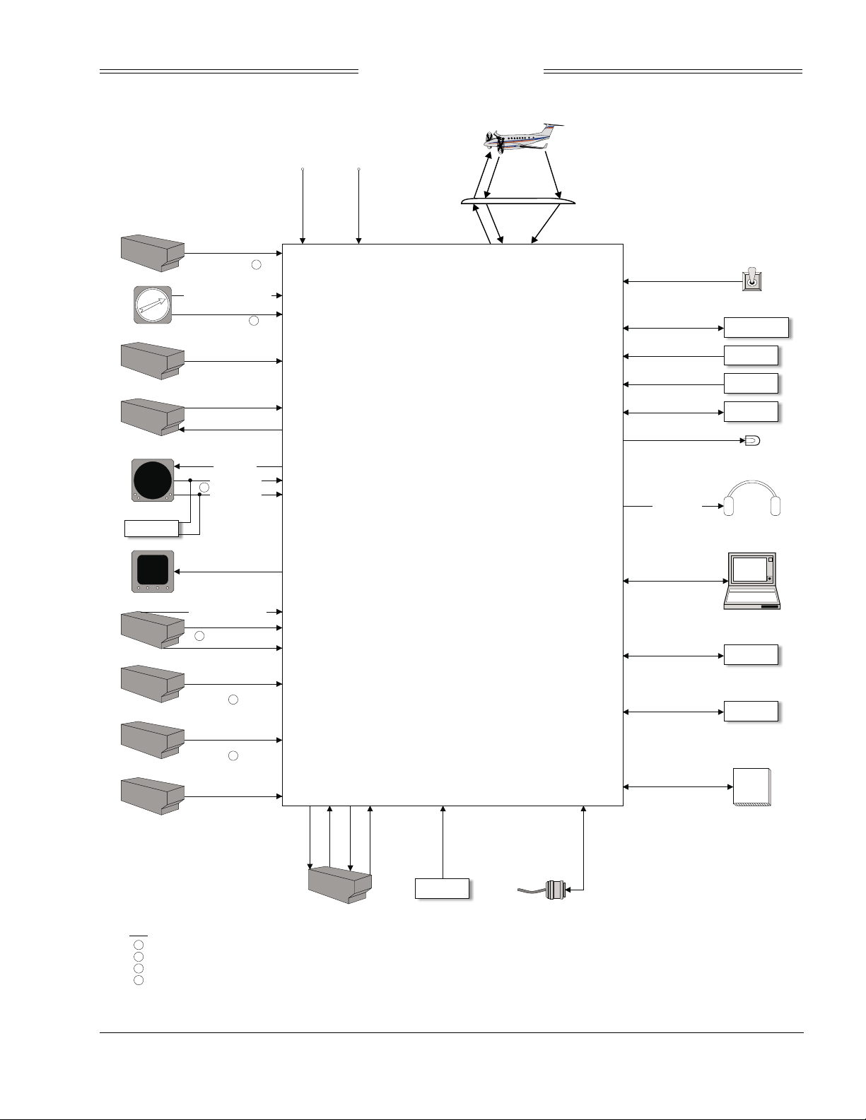
simplified block diagram of the system and their relationships is shown in figure 1-2.
1-2
Rev. A
Page 13

Preliminary
SKY899
Installation Manual
Major differences between SKYWATCH and SKYWATCH HP are listed below:
Category
• Active ATCRBS Display Range
• Active ATCRBS Surveillance Range
• Active ATCRBS Interrogation Power
• Number of Whisper-Shout Steps
• Active ATCRBS Interference Limiting
• ADS-B Surveillance
• Performance
• Closure Rate
• Antenna Configurations
• Aircraft Power Input
• Stepper Compass Input
• Radio Altitude Input
• Display Ranges (WX-1000 CDU)
• Installation Configuration Data
• Vertical Display Modes
SKY497 SKY899
6 nmi display range 15 nmi display range
11 nmi surveillance range 35 nmi surveillance range
Low-power interrogations High-power interrogations
4 Whisper-Shout steps 7 Whisper-Shout steps
No interference limiting TCAS I for TAS interference limiting
None ADS-B surveillance range 50 nmi
Single-sensor target tracking Multisensor target tracking
900 kn closure rate 1200 kn closure rate
Single directional antenna Multiple antenna configurations via
external ASU (future option)
11 V dc to 34 V dc 18 V dc to 32 V dc
Accepts stepper compass input Will not accept stepper compass input
Accepts only ARINC 429 radio
altitude
2 nmi and 6 nmi 2 nmi, 6 nmi, and 15 nmi
Connector configuration pins System configuration module
Normal, Above, & Below ±9,000ftNormal, Above, Below & Unrestricted
Accepts both analog and ARINC 429
radio altitude
±9,900 ft
1-3
Rev. A
Page 14

Preliminary
SKY899
Installation Manual
Unrestricted (UNR)
Look Up (ABV)
Normal (NRM)
Max. Display Range
Max. Display Range
Max. Display Range
4 nmi
0.55 nmi
0.2 nmi
S
e
n
s
i
t
i
T
h
i
s
a
r
e
a
S
e
n
s
i
t
i
T
h
i
s
a
r
e
a
v
ity
or 2
vity L
or 30
A
l
e
v
e
L
*
s
d
n
o
c
e
s
0
B
l
e
v
e
*
*
s
d
n
o
c
e
s
+9900 ft
+9000 ft
Intruder Aircraft
+2700 ft
+1200 ft
+800 ft
+600 ft
0 ft
–600 ft
–800 ft
–1200 ft
Look Down (BLW)Look Down (BLW)
–2700 ft
Not To Scale
–9000 ft
–9900 ft
*15 seconds for non-altitude reporting intruder aircraft
**20 seconds for non-altitude reporting intruder aircraft
Traffic Advisory Symbol
Other Traffic Symbol
Figure 1-1. Vertical Display Modes
1-4
Rev. A
Page 15
Preliminary
SKY899
Installation Manual
Intruder Aircraft
Encoding Altimeter
Synchro XYZ Compass
GPWS/TAWS
WX-1000 Processor
WX-1000 CDU
Control Panel
Alternate 429 Display
Radio Altimeter
ADC
AHRS
GPS Navigation System
Barometric Altitude
(Gilham Code)
Magnetic Heading Valid
Magnetic Heading
(Synchro XYZ)
Audio Inhibit
Power On/Off
1
Pilot Controls
Alternate 429 Display Data
(ARINC-429)
Radio Altitude Valid
Radio Altitude
4
Radio Altitude
(ARINC-429)
Barometric Altitude
(ARINC-429)
Magnetic Heading
(ARINC-429)
GPS Nav Data
(ARINC-429)
State
WX-1000
Video
WX-1000
Controls
CDU Video
(Analog)
2
3
2
3
+28 VDC +28 VDC Return
Transponder
Interrogations
Transponder
Interrogations
SKYWATCH HP
Transmitter/Receiver/Computer
(TRC899)
®
Transponder
Replies
Transponder
Replies
ADS-B Squitter
Broadcasts
ADS-B Squitter
Broadcasts
System Mode Switch
State
Suppression Bus
State
Landing Gear
State
Weight-On-Wheels
State
Bidirectional
Discrete I/O (1)
Indicator Lamp
Outputs (3)
Audio Output
Diagnostic Data
(RS-232)
Auxiliary Serial Data
(RS-232)
Auxiliary Serial Data
(RS-422)
Flash Card
Data
System Mode Switch
Aircraft
Suppression Bus
Landing Gear
Squat
Switch
Discrete I/O
Indicator
Lamps
Aircraft
Audio
System
Laptop Computer
Auxiliary
RS-232 Port
Auxiliary
RS-422 Port
Flash Card
TX Coord
(ARINC-429)
Mode S Transponder
Notes:
1
Power On/Off and Pilot Controls are wired discretely when using an external display
2
Barometric altitude can be obtained from any of these sources
Magnetic heading can be obtained from any of these sources
3
Radio altitude can be obtained from analog or ARINC 429 sources
4
(Future Option)
(ARINC-429)
(ARINC-429)
(ARINC-429)
Comm-A
Comm-B
XT Coord
Figure 1-2. SKY899 System Block Diagram
RX Data
ARINC-429
429 RX Port
Settings
Configuration
System Configuration Module
1-5
Rev. A
Page 16

Preliminary
SKY899
Installation Manual
The following table identifies the components which make-up the SKY899 system.
Table 1-1. SKY899 System
COMPONENT PART NUMBER
TRC899 Transmitter Receiver Computer 805-11900-001
System Configuration Module 814-18005-001*
WX-1000/SKY497 Display (Optional) 78-8060-5900-x**
Directional Antenna
NY156 805-10003-001
NY164 805-10890-001
* System Configuration Module is included in the installation kit P/N 817-11900-xxx (see table 1-2).
** Dash numbers identify different versions (refer to para 1.4.2).
1.3.1 TRC899 Transmitter Receiver Computer P/N 805-11900-xxx
The TRC is mounted in a mounting tray supplied with the installation kit (see table 1-2). The standard
tray (figure 1-3) will meet the requirements for fixed wing aircraft. A ruggedized version of the tray (figure
1-4) is required for rotorcraft installations.
To meet different space requirements, the I/O signal connector (P1) will accommodate either a straight or
right-angle backshell. TRC installation kits (see table 1-2) include either a straight backshell or right-angle
backshell (see figure 1-5).
1-6
Rev. A
Page 17

Preliminary
SKY899
Installation Manual
Table 1-2. TRC Installation Kit P/N 817-11900-xxx
KIT P/N DESCRIPTION QUANTITY PART NUMBER
817-11900-001 For Installation on Fixed-Wing Aircraft with Straight 1.5 inch
(3.8 cm) Backshell Consists of:
Standard Mounting Tray Assembly 1 805-10870-001
1.5" (3.8 cm) Straight Backshell 1 613-10039-001
I/O Connector, 100-Position, Female, (Mil-C-38999 Series III) 1 605-10251-001
(Includes #22D Crimp Terminals)
Spare Terminals for I/O Connector 10 M39029/56-348
Power Connector, 3-Position, Straight Plug 1 MS3126F12-3S
(Includes #16 Crimp Terminals)
Spare Terminals for Power Connector (M39029/32-247) 2 607-10018-001
System Configuration Module Assembly 1 814-18005-001
817-11900-002 For Installation on Fixed-Wing Aircraft with Straight 2.5 inch
(6.4 cm) Backshell Consists of:
Standard Mounting Tray Assembly 1 805-10870-001
2.5" (6.4 cm)Straight Backshell 1 613-10042-001
I/O Connector, 100-Position, Female, (Mil-C-38999 Series III) 1 605-10251-001
(Includes #22D Crimp Terminals)
Spare Terminals for I/O Connector 10 M39029/56-348
Power Connector, 3-Position, Straight Plug 1 MS3126F12-3S
(Includes #16 Crimp Terminals)
Spare Terminals for Power Connector (M39029/32-247) 2 607-10018-001
System Configuration Module Assembly 1 814-18005-001
817-11900-003 For Installation on Fixed-Wing Right-Angle (90°) Backshell
Consists of:
Standard Mounting Tray Assembly 1 805-10870-001
Right-Angle (90°) Backshell 1 613-10043-001
I/O Connector, 100-Position, Female, (Mil-C-38999 Series III) 1 605-10251-001
(Includes #22D Crimp Terminals)
Spare Terminals for I/O Connector 10 M39029/56-348
Power Connector, 3-Position, Straight Plug 1 MS3126F12-3S
(Includes #16 Crimp Terminals)
Spare Terminals for Power Connector (M39029/32-247) 2 607-10018-001
System Configuration Module Assembly 1 814-18005-001
817-11900-004 For Installation on Rotorcraft with 2.5 inch (6.4 cm) Backshell
Ruggedized Mounting Tray Assembly 1 805-10870-003
2.5" (6.4 cm)Straight Backshell 1 613-10042-001
I/O Connector, 100-Position, Female, (Mil-C-38999 Series III) 1 605-10251-001
(Includes #22D Crimp Terminals)
Spare Terminals for I/O Connector 10 M39029/56-348
Power Connector, 3-Position, Straight Plug 1 MS3126F12-3S
(Includes #16 Crimp Terminals)
Spare Terminals for Power Connector (M39029/32-247) 2 607-10018-001
System Configuration Module Assembly 1 814-18005-001
817-11900-005 For Installation on Rotorcraft with Right-Angle (90°) Backshell
Consists of:
Ruggedized Mounting Tray Assembly 1 805-10870-003
Right-Angle (90°) Backshell 1 613-10043-001
I/O Connector, 100-Position, Female, (Mil-C-38999 Series III) 1 605-10251-001
(Includes #22D Crimp Terminals)
Spare Terminals for I/O Connector 10 M39029/56-348
Power Connector, 3-Position, Straight Plug 1 MS3126F12-3S
(Includes #16 Crimp Terminals)
Spare Terminals for Power Connector (M39029/32-247) 2 607-10018-001
System Configuration Module Assembly 1 814-18005-001
1-7
Rev. A
Page 18

Preliminary
SKY899
Installation Manual
RETAINER CUPS
HOLD-DOWN KNOBS
(2-PLACES)
DIMENSIONS ARE IN INCHES (MILLIMETERS)
NOTE
REAR HOLD-DOWN PINS
(2-PLACES)
G
O
C
C
L
G
O
C
3
.
8
4
(
9
7
.
5
M
)
A
X
.
3.37
(85.6)
MAX.
1
(
0
5
7
.
)
0
1
.
9
1
(
0
7
.
)
6
2
.
0
7
1
(
4.15
(105.4)
MAX.
G
O
C
5
1
.
)
2
.
9
2
1-8
Rev. A
4
4
.
3
)
1
4
.
1
4
.
3
(
X
A
M
5
8
.
1
0
.
7
4
(
A
M
)
.
X
Figure 1-3. Standard TRC Mounting Tray (P/N 805-10870-001)
Page 19

Preliminary
SKY899
Installation Manual
DIMENSIONS ARE IN INCHES (MILLIMETERS)
NOTE
DOES NOT INCLUDE SCREW
COG
C
L
COG
9
6
.
5
)
5
.
4
4
1
(
4
.
(
3
1
4
1
0
.
2
)
HEADS
5
.7
0
)
.1
9
1
(
3.66
(93.0)
MAX.
3
0
2
.
1
)
6
.
0
3
(
6
3
.
3
)
1
3
.
9
3
3
.
(
X
A
M
0
7
.
1
)
2
.
3
4
(
.
X
A
M
Figure 1-4. Ruggedized TRC Mounting Tray (P/N 805-10870-003)
DIMENSIONS ARE IN INCHES (MILLIMETERS)
4.75
(120.7)
REF.
NOTE
4.25
(108.0)
REF.
3.25
(82.6)
REF.
STRAIGHT
BACKSHELL
P/N 613-10042-001
Figure 1-5. P1 Connector Dimensions (Reference Only)
SPLIT ELBOW
90° BACKSHELL
P/N 613-10043-001
1-9
Rev. A
Page 20

Preliminary
SKY899
Installation Manual
C
O
G
4.15 - REF
(105.4)
DIMENSIONS ARE IN INCHES (MILLIMETERS)
NOTE
A
e
r
o
s
p
a
c
e
J
I
N
J
1
T
E
R
C
O
N
N
E
C
T
9
J
1
0
J
1
1
3
.5
6
±
(9
0
.0
0
.4
3
1
±
.8
)
7.62
(193.0)
MAX.
G
O
C
4.15
(105.4)
0
0
.
1
F
E
R
4
.
5
2
(
J
8
P
O
W
)
E
R
M
J
E
M
O
R
C
J
7
T
E
S
1
2
Y
C
O
T
A
R
D
5
6
.
)
5
.5
3
4
1
(
1
.
7
1
(
4
3
.
4
)
O
C
2
G
1
1
3
(
G
4
0
.
0
)
±
0
.
2
1
5
.
±
.0
8
Figure 1-6. TRC899 Transmitter Receiver Computer (TRC)
1.3.2 System Configuration Module P/N 814-18005-001
The system configuration module is used to store aircraft installation dependent information via the
service menu. The system configuration is read from the module during turn-on. The module is included in
the installation kit and is designed to be installed inside the backshell of connector P1.
1-10
Rev. A
Page 21

Preliminary
SKY899
Installation Manual
1.3.3 Display (Alternate or WX-1000/SKY497 Display P/N 78-8060-5900-x)
The display used is installation dependent. If installing to meet the requirements for a TCAS I installation
an alternate display device (i.e., EFIS, MFD, IVSI, weather radar indicator) approved for displaying TCAS
I information is required. If installing to meet requirements for a TAS installation an alternate display
device, the WX-1000/SKY497 display, or both can be used as primary means for displaying traffic
information.
When interfaced to both displays (alternate display and WX-1000/SKY497 display),
display functions can
be linked together or separate depending on the capabilities of the alternate display. When installed with
an alternate display device only, the service menu cannot be accessed via the display, therefore a terminal
device (i.e., laptop) is required for system setup and post-installation checkout (see appendix F). If both
displays are connected the service menu can be accessed by the WX-1000/SKY497 display only.
The SKY899 is designed to transmit traffic information to the alternate display device via our ARINC-429
bus interface (100 kHz fixed speed). Refer to display manufacturer instructions for installation details.
WX-1000/SKY497 Display P/N 78-8060-5900-x. To operate with SKYWATCH HP, existing WX-1000
displays must conform to TSO-C113. If the equipment tag on the back of the unit (see figure 1-7) does not
identify SKYWATCH and TSO-C113, return the display to the factory for modification. To schedule
workload and ensure a quick turn around, a return authorization will be required. Call BFG Avionics
Systems Customer Service (1-800-453-0288 or 1-616-949-6600) for details.
Stormscope
Weather Mapping Systems
Series II
R
/
TRAFFIC ADVISORY SYSTEM
WX-1000 / SKY497 DISPLAY
78-8060-5900-9 TSO C110a, C113
Pat. USA 4,023,408;U.K. 1,529,624; Germany 26-00-658; Others Pend.
SERIAL NO.
ace
ace
A
erosp
A
erosp
2.3lb. 1.0kg.
BFGoodrich Avionics Systems, Inc.
Grand Rapids, MI USA
1
2
3
4
5
TAG MUST IDENTIFY
SKYWATCH AND TSO-C113.
Figure 1-7. WX-1000/SKY497 Display Equipment Tag
The display unit mounts in a standard 3ATI panel cutout. All connections to the display are made through
a single 25-position male D-subminiature connector on the back panel. Figure 1-8 depicts the indicator
dimensions. The last digit of the part number identifies the different versions (refer to para 1.4.2).
Table 1-3 lists the contents of an installation kit supplied with each unit.
Table 1-3. WX-1000/SKY497 Display Installation Kit P/N 817-10802-001
QUANTITY PART NUMBER DESCRIPTION
4 26-1001-6374-5 Screw, Machine, 6-32 x 3/4 in. Phillips Pan Head, Black Oxide
1 26-1003-5633 Connector, 25 Position Recpt. Shell
1 26-1006-2426-6 Connector Backshell, DB25
2 26-1006-1089-3 Connector Lock Post Assembly
25 26-1003-4274-9 Connector Socket, Screw Machine (M39029/63-368)
1-11
Rev. A
Page 22

Preliminary
SKY899
Installation Manual
C
L
3.37
(85.6)
0.55
(14.0)
NOTE
C.G.
3.37
C
L
(85.6)
DIMENSIONS ARE IN INCHES (MILLIMETERS)
3.89
(98.8)
3.18
(80.8)
J101
3.18
(80.8)
1-12
Rev. A
C
L
0.17 ±0.02
(4.3 ±0.5)
0.08
(2.0)
C
C.G.
3.40
(86.4)
8.07
(205.0)
L
P101
1.30
(33.0)
Figure 1-8. WX-1000/SKY497 Display
Page 23

Preliminary
SKY899
Installation Manual
1.3.4 Directional Antenna (NY156 P/N 805-10003-001 or NY164 P/N 805-10890-001)
The directional antenna is a teardrop-shaped antenna. Connections are made through two TNC and one
BNC connector. The antenna is sealed against environmental extremes and is non-repairable. To ensure a
tight seal between the airframe and antenna, an O-ring seal (i.e., an O-ring groove for an MS28775-044 Oring) has been incorporated into the design. An O-ring is supplied with each antenna and must be installed
when mounting the antenna.
To fit specific airframes, a special adapter plate is also required. The adapter plate is included in the
installation kit shipped with each system. Refer to table 1-4 for a list of installation kits associated with
various airframes. For aircraft not listed, contact the aircraft manufacturer for information relative to the
radius of the area where the antenna is to be mounted. Table 1-5 lists the contents of each installation kit.
The installation kits differ only in the size of the special airframe adapter plate. Figure 1-9 depicts the
antenna dimensions.
Table 1-4. Airframe Installation Kits
INSTALLATION KIT
MANUFACTURER AIRFRAME
AEROSPATIALE ATR-42 817-10009-001
AGUSTA A109 817-10009-006
BAE/RAYTHEON HAWKER 400, 600, 700, 800, and 1000 817-10009-004
BEECH
BELL 206, 407, 427 817-10009-006
CANADAIR CHALLENGER 600 and 601 817-10009-005
CESSNA CITATION III, VI, VII
COMMANDER 114 817-10009-006
DASSAULT FALCON 10, 20, 50
DEHAVILLAND Dash 7/8 817-10009-001
EMBREAR EMB 110, 120 817-10009-001
EUROCOPTER EC135 817-10009-006
FAIRCHILD METROLINER, METROLINER III, MERLIN 817-10009-001
FOKKER F28 817-10009-003
GULFSTREAM G-I, G-II, and G-III 817-10009-001
IAI WESTWIND 1125 817-10009-001
LEARJET LEARJET 31, 35, 36, 55, and 60 817-10009-004
MITSUBISHI MU-2 817-10009-002
MOONEY M20 817-10009-006
PILATIS PC-12 817-10009-001
PIPER CHEYENNE 400LS
SAAB SF-340 817-10009-001
SABRELINER SABRE 65 817-10009-001
SHORTS 360 817-10009-001
SIKORSKY S-76 817-10009-006
SOCATA TBM-700
BEECHJET, KING AIR 90, 100, 200, 300, and 350
BARON 33, 35, 36, 55, 58, BE-99, 1300, & 1900C/D
CITATIONJET, CITATION I, II, V
182, 210, 337, 401, 414, 425, 441
FALCON 900
NAVAJO
MIRAGE, MALIBU
SARATOGA, SENECA
TB20
PART NUMBER
817-10009-001
817-10009-002
817-10009-001
817-10009-004
817-10009-006
817-10009-001
817-10009-005
817-10009-001
817-10009-002
817-10009-005
817-10009-006
817-10009-001
817-10009-006
1-13
Rev. A
Page 24

Preliminary
SKY899
Installation Manual
Table 1-5. Directional Antenna Installation Kit 817-10009-xxx
SUPPLIED PARTS *
KIT PART NUMBER PART NUMBER DESCRIPTION QUANTITY
817-10009-001 800-10066-001 Special Adapter Plate, 40 Inch (101.6 cm) Radius 1
817-10009-002 800-10066-002 Special Adapter Plate, 63 Inch (160.0 cm) Radius 1
817-10009-003 800-10066-004 Special Adapter Plate, 80 Inch (203.2 cm) Radius 1
817-10009-004 800-10066-003 Special Adapter Plate, 32 Inch (81.3 cm) Radius 1
817-10009-005 800-10066-005 Special Adapter Plate, 47 Inch (119.4 cm) Radius 1
817-10009-006
(No Adapter Plate)
100-10022-001*
101-10027-001*
Screw, 10-32 x 1 PPH SS (MS51958-67)
Stop Nut, 10-32 (MS21044C3)
* Hardware supplied with all kits.
4
4
DIMENSIONS ARE IN INCHES (MILLIMETERS)
NOTE
FWD
DO NOT PAINT
FORWARD
6.23 ±0.08
(158.2 ±2.0)
1.30
(33.0)
1-14
Rev. A
0.725
(18.4)
SUM PORT
(Blue Band)
PROBE PORT
(Black Band)
5.06
(128.5)
11.12
(282.4)
DIFFERENCE PORT
(Red Band)
5.71
(145.0)
0.45
(11.4)
Figure 1-9. NY156/NY164 Directional Antenna
Page 25

Preliminary
Installation Manual
1.4 SPECIFICATIONS
1.4.1 Transmitter Receiver Computer (TRC)
SKY899
PART NUMBER:
SIZE:
WEIGHT:
OPERATING TEMPERATURE:
STORAGE TEMPERATURE:
OPERATING ALTITUDE:
COOLING:
POWER REQUIREMENTS:
TRACKING CAPABILITY:
SURVEILLANCE RANGE:
DISPLAY RANGES:
805-11900-001 - TRC899
Approximately 12.52 inches (31.90 cm) Deep
Approximately 3.56 inches (9.04 cm) Wide
Approximately 7.62 inches (19.36 cm) High
Approximately 8.88 lb (4.03 kg) Not Including Mounting Tray
Approximately 9.76 lb (4.43 kg) With Standard Mounting Tray
Approximately 10.89 lb (4.94 kg) With Ruggedized Mounting Tray
-55 to +70 degrees Celsius (-67 to +158 degrees Fahrenheit)
-55 to +85 degrees Celsius (-67 to +185 degrees Fahrenheit)
55,000 feet (Maximum)
Conduction and Forced Air (Internal Fan) Convection
18 to 32 V dc, 2 Amps @ + 28 V dc(Maximum)
Up to 35 intruder aircraft (displays only the 8 highest priority aircraft)
Horizontal tracking radius:
35 nmi Maximum ATCRBS Surveillance
50 nmi Maximum ADS-B Surveillance
Relative altitude tracking range:
±10,000 ft maximum
Horizontal display ranges:
2, 6 & 15 nmi (WX-1000/SKY497 Display)
Relative altitude display ranges:
±2,700 ft (normal mode)
+9,000 ft to -2,700 ft (above mode/look up)
+2,700 ft to -9,000 ft (below mode/look down)
+9,900 ft to -9,900 ft (unrestricted)
RANGE ACCURACY:
BEARING ACCURACY:
ALTITUDE ACCURACY:
CERTIFICATION: *
RTCA COMPLIANCE:
± 0.05 nmi (Typical)
With NY156 Antenna - 5° RMS (Typical) 30° Peak Error
With NY164 Antenna - 7° RMS (Typical) 30° Peak Error
±200 ft
USA (FAA) TSO C118 (TCAS I) & C147 (TAS) Refer to FSAW 98-04B for Flight Standards
Service policy concerning follow-on field approvals.
Software DO178-B Level D
DO-160D Category F2XBAB[(SBM)(UG)]XXXXXXZBABARRLXXXXXXA
* Listed are current certifications at time of publication, contact Field Service Engineering at 1-800-453-
0288 or 1-616-949-6600 for latest certification information.
Rev. A
1-15
Page 26

Preliminary
1.4.2 WX-1000/SKY497 Display
PART NUMBER DEFINITION:
78-8060-5900-8 (Black Bezel)
78-8060-5900-9 (Gray Bezel)
SIZE:
Height: 3.37 inches (8.56 cm)
Width: 3.37 inches (8.56 cm)
Depth: 8.24 inches (20.92 cm)
WEIGHT:
2.3 lb (1.0 kg)
OPERATING TEMPERATURE:
-20 to +55 degrees Celsius (-4 to +131 degrees Fahren heit)
STORAGE TEMPERATURE:
-55 to +70 degrees Celsius (-67 to +158 degrees Fahrenheit)
OPERATING ALTITUDE:
55,000 feet (Maximum)
TSO COMPLIANCE:
C110a & C113
SKY899
Installation Manual
RTCA COMPLIANCE:
DO-160C F1-CA(NBM)XXXXXXZXXXZUAXXXXXX
POWER REQUIREMENTS:
+15/-15 V dc, 0.7 A (Maximum)
1.4.3 Directional Antenna
PART NUMBER: 805-10003-001 (NY156)
805-10890-001 (NY164)
SIZE: 1.3 inches (3.25 cm) high
6.23 in (15.82 cm) wide
11.12 in (27.94 cm) deep
WEIGHT: 2.3 lb (1.04 kg)
SPEED: Rated to 600 knots (0.9 Mach) @ 25,000 feet.
FREQUENCY: 1030-1090 MHz
TSO CATEGORY: C118
ENVIRONMENTAL
CATEGORY: DO-160C F2-AC(CLM)XSFDFSXXXXXXXL(2A)X
FINISH: Gloss white Skydrol resistant polyurethane paint
1.5 MODIFICATIONS & SOFTWARE REVISIONS
Modifications (MODS) and software revisions for the TRC899 are identified by an entry on the S/N & I.D.
tag. The system software revision is a collective designator for all software/firmware installed within the
TRC899.
software versions are listed below.
SKY HP software version can be verified via the service menu. Hardware modifications and
Hardware Modifications - None at the time of publication.
1-16
Rev. A
Page 27

Preliminary
SKY899
Installation Manual
Table 1-6. TRC899 Software Revisions
SYSTEM
REVISION
1.00 1.00 Original production release.
1.6 INTERFACE
The electrical characteristics of all input and output signals are detailed in Appendix A. Listed below in
table 1-7 is the minimum equipment required to interface with the SKY899. See chapter 2 for details.
SURVEILLANCE
MODE
SKY HP
VERSION
DESCRIPTION
Table 1-7. Minimum Interface Equipment Required
AVIONICS EQUIPMENT
GPS NAV
MAGNETIC HEADING
RADIO ALTITUDE
SQUAT SWITCH (WOW)
BAROMETRIC ALTITUDE
LANDING GEAR SWITCH
SUPPRESSION BUS
(PUSHBUTTONS)
PILOT CONTROLS
EXTERNAL LAMPS
AUDIO INHIBIT (GPWS)
AUDIO SYSTEMS
ATCRBS
(Active Only)
ATCRBS & ADS-B X X
X
Required.
① Optional but will enhance performance. (See paragraphs 2.7 thru 2.23 for details.)
② Required if Terrain Warning System (GPWS) is installed.
③ Only if Alternate Display requires it, see display manufacturer's instructions.
1.7 EQUIPMENT REQUIRED BUT NOT SUPPLIED
Antenna Cables The installer will supply all antenna cables and connectors. The directional
Use of any cable not meeting BFGoodrich Avionics Systems specifications
voids all system warranties.
①
antenna requires three cable assemblies; sum (Sigma Port), bit probe
(Probe Port) and difference (Delta Port). Cable attenuation for the sum and
difference ports must not exceed 2.5 dB. Table 1-8 identifies U. S. vendors
who sell approved cables by the foot. Table 1-9 provides a cable to connector
cross-reference.
RG142B or equivalent may be used for the bit probe cable. Attenuation for
the bit probe cable must not exceed 6 dB.
①①
X
①
X
NOTE
XX
①
XX
②③ ③
②③ ③
X
X
1-17
Rev. A
Page 28

Preliminary
SKY899
Installation Manual
Table 1-8. Directional Antenna SIGMA and DELTA Port Cable Vendors
Electrical & Mechanical Technologies (EMTEQ)
1-888-679-6170
262-679-6170
FAX 262-679-6175
Attenuation
Part Number
PFLX195-100 10.81 2.7 21.8 0.50
PFLX240-100 9.76 4.5 25.0 0.75
PFLX340-100 6.3 7.2 38.2 0.88
Part Number
352001 12.2 2.7 15 0.81
311601 8.7 5.5 26 1.15
311201 5.56 8.5 41 1.59
310801 3.63 16.1 63 2.26
Part Number
S33141 7.2 6.5 32 1.5
S55122 5.7 8.2 40 1.6
S22089 3.8 18 61 2.5
(dB/100 ft 1.0 gHz)
Attenuation
(dB/100 ft 1.0 gHz)
Attenuation
(dB/100 ft 1.0 gHz)
Weight (lb)
(per 100 ft)
Electronic Cable Specialists
1-800-327-9473
414-421-5300
FAX 414-421-5301
Weight (lb)
(per 100 ft)
PIC Wire and Cable
1-800-742-3191
262-246-0500
FAX 262-246-0450
Weight (lb)
(per 100 ft)
Maximum Length
(ft)
Maximum Length
(ft)
Maximum Length
(ft)
Minimum Bend
Radius (in)
Minimum Bend
Radius (in)
Minimum Bend
Radius (in)
If cable weight is not a consideration, select lowest loss cable. Contact cable vendors before installation.
New low-loss light-weight cables may be available.
1-18
Rev. A
Page 29

Preliminary
SKY899
Installation Manual
Table 1-9. Cable to Connector Reference
Electrical & Mechanical Technologies (EMTEQ)
1-888-679-6170
262-679-6170
FAX 262-679-6175
Cable Part Number TNC Straight TNC Right Angle BNC Straight BNC Right Angle
PFLX195-100 TMS195-1 TMR195-1 BMS195-1 BMR195-1
PFLX240-100 TMS240-1 TMR240-1 BMS240-1 BMR240-1
PFLX340-100 TMS340-1 TMR340-1 BMS340-1 BMR340-1
Electronic Cable Specialists
1-800-327-9473
414-421-5300
FAX 414-421-5301
Cable Part Number TNC Straight TNC Right Angle BNC Straight BNC Right Angle
311601 CTS922 CTR922 CBS922 CBR922
311201 CTS122 CTR122 CBS122 CBR122
310801 CTS022 CTR022 CBS022 CBR022
352001 CTS3522 CTR3522 CBS3522 CBR3522
PIC Wire and Cable
1-800-742-3191
262-246-0500
FAX 262-246-0450
Cable Part Number TNC Straight TNC Right Angle BNC Straight BNC Right Angle
S33141 190308 190309 190312 190313
S55122 190608 190609 190612 190613
S22089 190408 190409 190412 190413
Antenna Sealant For pressurized aircraft, use a sealant that meets the requirements of SAE
AMS-S-8802 such as Flamemaster® CS3204 class B. For non-pressurized
aircraft, use a non-corrosive sealant that meets the physical requirements
of MIL-A-46146 such as General Electric RTV162.
Circuit Breaker 5 Amp
Connector Installation Antenna Cables See table 1-8.
Tool M22520/5-01
Die M22520/5-19 (EMTEQ Cable PFLX195-100)
Die M22520/5-43 (EMTEQ Cable PFLX240-100)
Die M22520/5-35 (EMTEQ Cable PFLX340-100)
Die M22520/5-19 (ECS Cable 311601)
P1 Interconnect Crimping Tool M22520/2-01
Die M22520/5-61 (ECS Cable 311201)
Die M22520/5-21 (ECS Cable 310801)
Die 190318 (PIC Cable S33141)
Die 190418 (PIC Cable S22089)
Die 190618 (PIC Cable S55122)
Positioner M22520/2-07
Insertion MS27495 A22M
Removal MS27495 R22M
1-19
Rev. A
Page 30

Preliminary
SKY899
Installation Manual
Connector Installation
(Continued)
P8 Power Crimping Tool M22520/1-01
Positioner M22520/1-02
Insertion MS24256A16
Removal MS24356R16
P101 Display Crimping Tool M22520/2-01
Positioner M22520/2-08
Insertion/Removal M81969/1-02
Data Cables RS-232, RS-422, and ARINC-429 data cables are #22 AWG (minimum)
twisted, shielded cables.
Flightline Tester Either the BFG TT391 Flightline Tester, IFR Systems TCAS-201 (with
TCAS I firmware) Ramp Test Set (Appendix C), or TIC T-49C Flightline
Tester (Appendix D). The test set is required to do the post installation
checkout.
Heading Input Cable This cable provides aircraft heading information to the SKY899. Cable that
meets the specification for SKY899 installation is available from suppliers
listed in table 1-10.
Table 1-10. Heading Input Cable Vendors
US
COMPANY
Dallas Avionics
1-800-527-2581
214-320-9776
FAX 214-320-1057
CABLE
P/N
WX-5
(6.84 lb/
100 ft)
Lamps
(external annunciators)
Electronic Cable
Specialists
1-800-327-9473
414-421-5300
FAX 414-521-5301
A.E. Petsche
817-461-9473
FAX 817-277-2887
EDMO Distributors
1-800-235-3300
805-295-6689
FAX 1-800-828-0623
FAX 805-295-6703
3N6607
(7.5 lb/
100 ft)
TZGYR
(6.84 lb/
100 ft)
WX-1000
SYNCHRO
PIC Wire and Cable
1-800-742-3191
262-246-0500
FAX 262-246-0450
External annunciators are required when using an alternate display that is
not capable of displaying above and below vertical modes. Lamp outputs
are switched to ground when active (LP1OUT & LP2OUT). Lamps should
be labeled ABV and BLW. An optional operation mode lamp can be
installed to show system has been switched from standby into operation
mode. Refer to paragraph 2.14, 2.15 and A.2. Lamps can be 12V or 28V
with maximum current 300 mA
WM25807
(7.2 lb/
100 ft)
1-20
Rev. A
Page 31

Preliminary
SKY899
Installation Manual
Miscellaneous Hardware
Oscilloscope
Power Cable For the power cable, use #16 AWG (minimum) twisted shielded pair cable
RS-232 Terminal Device
(e.g., Laptop Computer)
The installer must provide suitable hardware to attach the TRC Mounting
Tray. The following stainless steel fasteners are recommended:
Channel Mount: Four 8-32 UNC-2A pan head machine screws per
ANSI B18.6.3. (Six are required for the ruggedized
tray.)
or
Four 8-32 UNC-2A hex socket cap machine screws
per ANSI/ASME B18.3. (Six are required for the
ruggedized tray.)
Four No. 8 helical spring lockwasher per
ANSI/ASME B18.21.1. (Six are required for the
ruggedized tray.)
Flat Mount Eight 6-32 UNC-2A 100 degree flat head machine
screws per B18.6.3.
Required to verify SKY899 suppression pulse (100 µs ±5µs, +28 V dc).
(Beldon 83322, Alpha 2826/2, or equivalent).
Required if using an alternate display, (see Appendix E for instructions).
Terminal device is used for system setup, post installation checkout and
troubleshooting. Any computer, with RS-232 terminal emulation software
(e.g., Procomm®, HyperTerminal, etc.) may be used as the terminal device.
A standard 9-pin serial cable is required.
Surface Preparation Alodine® No. 1001 required for installation of the antenna.
Switches If an alternate display is used a separate ON/OFF switch is required. Any
general purpose SPDT toggle switch (3 A @ 28 V dc) may be used.
If the final configuration includes a WX-1000 Stormscope Weather Mapping
System, two external switches will be required. A SPST switch will be
required for the SKYWATCH/Stormscope display mode switch (SW1). A
DPDT switch will be required for the WX-1000 maintenance switch (SW2).
Any general purpose toggle switch (3 A @ 28 V dc) may be used.
WX-1000/SKY497 Display &
WX-1000 Processor Cable
This cable is used to connect the WX-1000/SKY497 display and/or WX-1000
processor to the TRC. Required connectors and contact pins are supplied in
the installation kit. Cable specifications and U.S. vendors are listed below
in table 1-11.
NOTE
Use of any cable not meeting BFG Avionics Systems specifications voids all
system warranties.
1-21
Rev. A
Page 32

Preliminary
Installation Manual
Table 1-11. Display Cable Vendors
U.S.
COMPANY
Dallas Avionics
1-800-527-2581
214-320-9776
FAX 214-320-1057
Electronic Cable Specialists
1-800-327-9473
414-421-5300
FAX 414-421-5301
A.E. Petsche
817-461-9473
FAX 817 277 2887
PIC Wire and Cable
1-800-742-3191
262-246-0500
FAX 262-246-0450
EDMO Distributors
1-800-235-3300
509-535-8280
FAX 1-800-828-0623
FAX 509-535-8266
SKY899
DISPLAY CABLE
P/N
WX-3 10.5
3N6715 16
TZDIS 13.1
WM25815 14.5
WX-1000 Display ---
WEIGHT
(LB PER 100 FT)
1.8 INSTALLATION APPROVAL
The SKY899 must be treated as a major alteration on F.A.A. form 337, if not installed under a type
certificate or supplemental type certificate. Aircraft mandated for TCAS I (i.e., part 91 & 135), must be
installed under a type certificate or supplemental type certificate, refer to FSAW 98-04B. Application for
approval may be made at any F.A.A. Flight Standards District Office.
1.9 WARRANTY INFORMATION
The SKY899 Traffic Alert/Advisory System is warranted for two years from the date of installation (not to
exceed 30 months from the date of shipment from BFGoodrich Avionics Systems) subject to the following
limitations.
1.9.1 Warranty Statement
BFGoodrich Avionics Systems, (hereinafter called BFGAS), warrants each item of new equipment
manufactured or sold by BFGAS to be free from defects in material and workmanship, under normal use
as intended, for a period of 30 months from date of shipment by BFGAS to an authorized facility, or 24
months from date of installation by an authorized facility, whichever occurs first. No claim for breach of
warranties will be allowed unless BFGAS is notified thereof, in writing, within thirty (30) days after the
material or workmanship defect is found.
The obligation of BFGAS shall be limited to replacing or repairing at its factory the equipment found
defective under terms of this warranty certificate; providing that such equipment is returned in an
approved shipping container, transportation charges prepaid, to BFGAS, Grand Rapids, Michigan, or such
other location as BFGAS may authorize. BFGAS reserves the right to have necessary repairs performed by
an authorized agency.
1-22
Rev. A
Page 33

Preliminary
SKY899
Installation Manual
This warranty shall not apply to any unit or part thereof which has not been installed or maintained in
accordance with BFGAS instructions, or has been repaired or altered in any way so as to adversely affect
its performance or reliability, or which has been subjected to misuse, negligence or accident.
This warranty is exclusive and is accepted by buyer in lieu of all other guaranties or warranties express or
implied, including without limitation the implied warranties of merchantability and fitness for a particular
purpose. Buyer agrees that in no event will BFGAS liability for all losses from any cause, whether based in
contract, negligence, strict liability, other tort or otherwise, exceed buyer’s net purchase price, nor will
BFGAS be liable for any special, incidental, consequential, or exemplary damages.
BFGAS reserves the right to make changes in design or additions to or improvements in its equipment
without the obligation to install such additions or improvement in equipment theretofore manufactured.
1.9.2 Related Policies and Procedures
1. If the original registered owner of a SKY899 system sells the aircraft in which the system is installed
during the warranty period, the remaining warranty may be transferred. Written notification of the
transaction must be submitted by the initial recipient of the warranty to:
ATTENTION: WARRANTY ADMINISTRATOR
BFGoodrich Avionics Systems
5353 52nd Street, S.E.
Grand Rapids, MI USA 49512
2. Equipment must be installed by a BFG Avionics Systems authorized dealer or installer. Installation of
equipment by facilities not specifically authorized will void the equipment warranty.
3. Notice of a claimed product defect must be given to BFG Avionics Systems or a designated BFG
Avionics Systems Service Agency within the specified warranty period.
4. A product which is defective in workmanship and/or material shall be returned to BFG Avionics
Systems via any Authorized Dealer with transportation charges prepaid. After correction of such
defects, the equipment will be returned to the Dealer, transportation prepaid by BFG Avionics
Systems via surface transportation. Any other means of transportation must be paid by the customer.
The risk of loss or damage to all products in transit shall be assumed by the party initiating the
transportation of such products. All items repaired or replaced hereunder shall be warranted for the
unexpired portion of the original warranty.
5. BFG Avionics Systems is in no way obligated or responsible for supporting or participating in the
costs of the installation warranty. The entire responsibility lies with the BFG Avionics Systems
Authorized Dealer making the installation. BFG Avionics Systems is only responsible for the product
warranties outlined in paragraph 1.9.1.
6. BFG Avionics Systems cannot authorize warranty credit for troubleshooting of other systems in the
aircraft in order to reduce noise interference with the SKY899 system.
1-23
Rev. A
Page 34

Preliminary
SKY899
Installation Manual
This page intentionally left blank.
1-24
Rev. A
Page 35

Preliminary
SKY899
Installation Manual
CHAPTER 2
INSTALLATION
2.1 INTRODUCTION
The information and instructions provided in this section are directed toward fixed-wing aircraft. The
complex nature of rotorcraft installations (e.g., antenna placement; composite versus metal blades,
available ground plane, rotor mast interference, strike kits, etc.) requires that each installation be
evaluated on a case-by-case basis. Before starting a rotorcraft installation, contact Field Service
Engineering at 1-800-453-0288 or 1-616-949-6600.
NOTE
Tolerances (unless otherwise indicated):
ANGLES ARE ± 1°
.00 TWO PLACE DECIMALS ARE ± .02
.000 THREE PLACE DECIMALS ARE ± .010
Installation must be made by qualified personnel, in conformance with applicable government regulations.
This information furnished is for convenience only.
NOTES
1. The conditions and test required for TSO approval of this article are minimum
performance standards. It is the responsibility of those installing this article either
on or within a specific type or class of aircraft to determine that the aircraft
installation conditions are within the TSO standards. The article may be installed
only if the installation is performed in accordance with Part 43 or the applicable
airworthiness requirements.
2. Installation instructions for the WX-1000 processor are detailed in the WX-1000
Installation Manual.
2.2 UNPACKING, INSPECTION AND STORAGE
CAUTION
The display and TRC are sensitive to electrostatic discharge (ESD) and may
be damaged if not handled correctly. Do not remove protective covers from
electrical connectors during unpacking. Touching an exposed connector may
cause electrostatic damage to equipment.
Carefully unpack the system and note any damage to shipping containers or equipment. Visually inspect
each component for evidence of damage. Compare the equipment received with that noted on the packing
list. Immediately report any missing items or evidence of damage to the carrier making the delivery. To
justify a claim, retain the original shipping container and all packing materials.
Every effort should be made to retain the original shipping containers for storage. If the original
containers are not available, a separate cardboard container should be prepared that is large enough to
accommodate sufficient packing material to prevent movement. The ambient temperature of the storage
area should not fall below -55 °C (-67 °F) or rise above 85 °C (185 °F).
Rev. A
2-1
Page 36
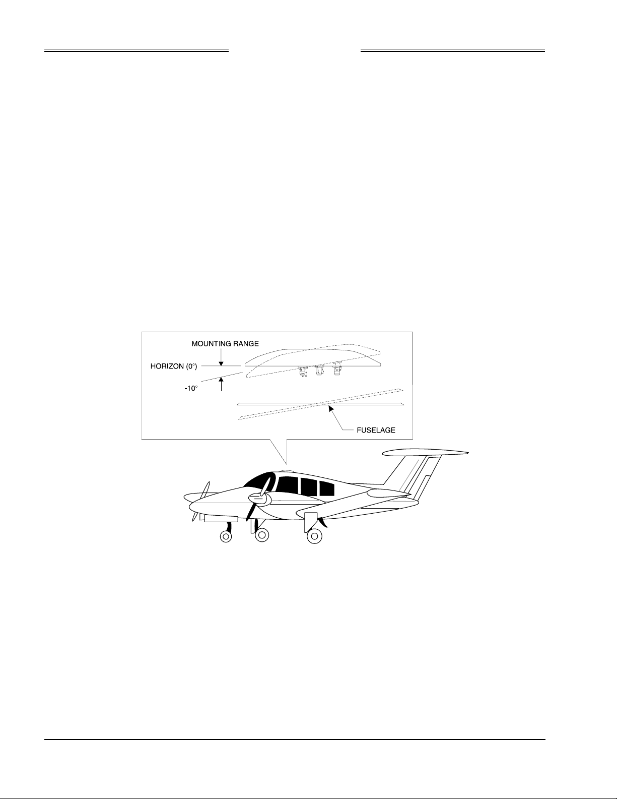
Preliminary
SKY899
Installation Manual
2.3 ANTENNA LOCATION
Location is an important factor for maximum antenna performance. Optimum location for a particular
aircraft type is usually available from the aircraft manufacturer. In selecting a location, consider the
following:
Directional Antenna The mounting site should be on the top forward fuselage, as close to the
centerline as possible, and within -10° of the in-flight horizon (see figure 2-1).
The optimum mounting point for maximum coverage is as far forward as
possible without exceeding the -10° forward pitch. If necessary, consideration
should be given to relocating other antennas to obtain the furthest forward
location for the directional antenna. The antenna should be mounted on the
aircraft with at least 20 dB isolation (about 30 inches (76.2 cm)) from other Lband frequency antennas and 24 inches (61.0 cm) from other antennas or
obstructions. The ground-plane should be as large as possible, a 30-inch (76.2
cm) ground-plane diameter is recommended.
The directional antenna can be bottom mounted only if a suitable top mount
location is not available. Each bottom mount installation must be evaluated on
a case-by-case basis. Before starting a bottom mount installation, contact Field
Service Engineering at 1-800-453-0288 or 1-616-949-6600.
Figure 2-1. Directional Antenna Mounting Location
2.4 TRC LOCATION
Typically the TRC is installed in the electronics bay. In selecting a location, consider the following:
Cable Length Cable runs should be as short as practicable in order to minimize potential
electrical interference. Cable length to antennas must not exceed the values listed
in table 1-6.
Cooling While the TRC has no special cooling requirements, it should be mounted to permit
adequate ventilation. Caution should be observed to not inhibit airflow from the
rear mounted fan. Allow at least three inches (8 cm) of rear clearance.
Pressurized Aircraft The TRC may mount inside or outside the pressure vessel. The TRC contains no
batteries or potentially explosive components and will operate up to 55,000 ft.
2-2
Rev. A
Page 37
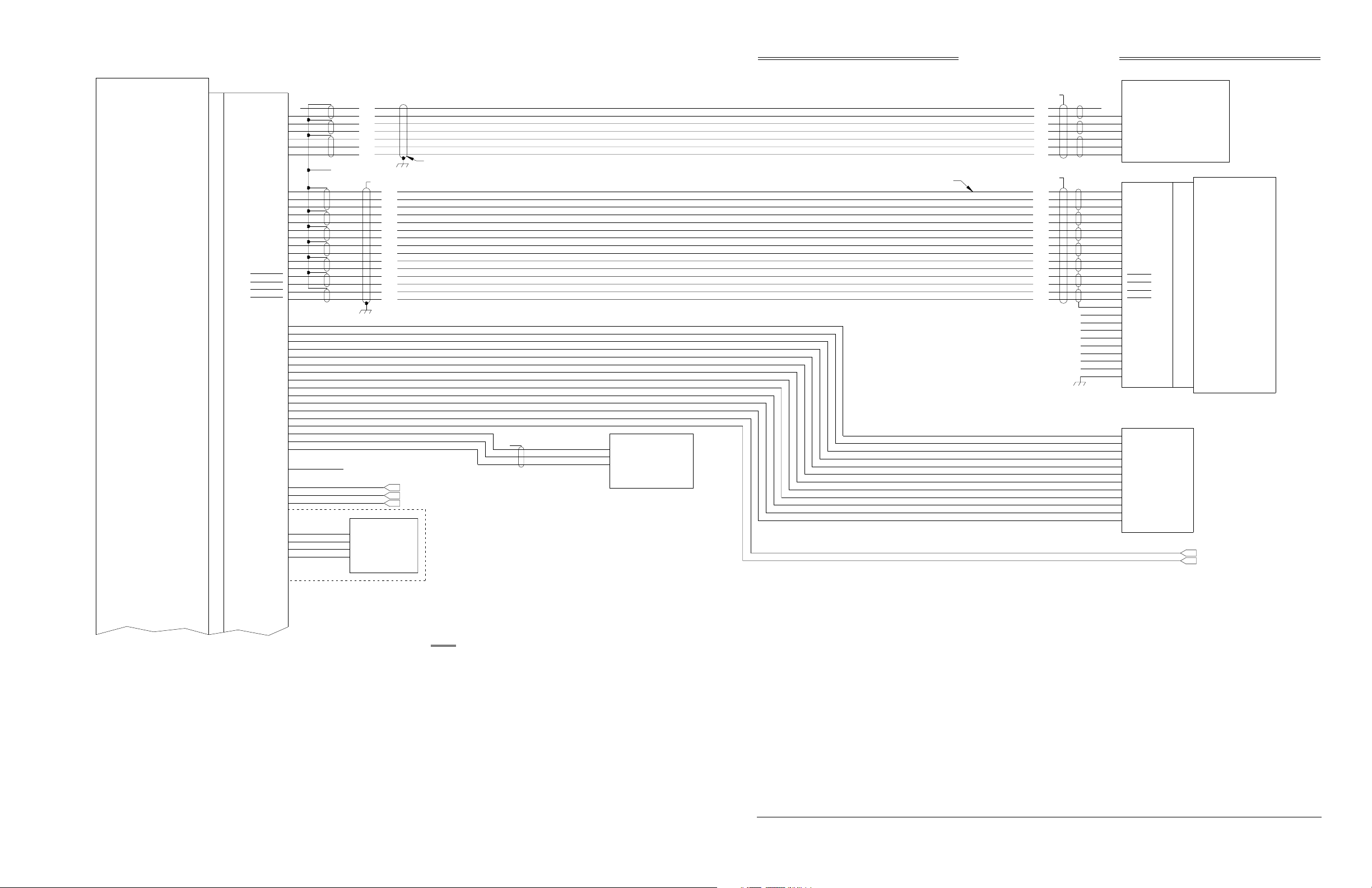
Preliminary
TRANSMITTER
RECEIVER
COMPUTER
UNIT
TRC899
P/O P/O
J1 P1
HEADING_FLG
HEADING_C
HEADING_H
HEADING_Z
HEADING_Y
HEADING_X
DPWR+15_OUT
DPWR-15_OUT
DSPLY_GND_OUT
HSYNC_OUT+
HSYNC_OUT-
VSYNC_OUT+
VSYNC_OUTVIDEO_OUT+
VIDEO_OUT-
ON/OFF_RET
SFTKEY1_IN
SFTKEY2_IN
SFTKEY3_IN
SFTKEY4_IN
ALT_COMN
RAD_ALT_IN_HI
RAD_ALT_IN_LO
RADIO_ALT_FLG
DISCRETE
OPER_MODE
PLUG_GND
ON/OFF
ALT_A1
ALT_A2
ALT_A4
ALT_B1
ALT_B2
ALT_B4
ALT_C1
ALT_C2
ALT_C4
ALT_D2
ALT_D4
SQUAT
GEAR
LP1OUT
LP2OUT
3.3V
SDA
SCL
51
50
49
48
47
46
8
9
10
11
12
13
22
16
17
4
5
18
19
20
21
56
57
58
59
60
61
67
68
69
70
71
72
24
33
6
7
14
32
31
66
85
2
92
99
100
N/C
TP
TP
WHT
TP
BLU
TP
ORN
TP
RED
GRN
TP
BLKTP
YEL
TP
SEE NOTE 13
BLU
ORN
WHT
BLU
BLU
WHT
BLU
ORN
WHT
WHT
SEE NOTE 6
N/C
PERSONALITY PLUG
3.3V
PLUG_GND
SDA
SCL
SEE NOTE 6
WHT
ORN
BLU
WHT
BLU
WHT
BLU
WHT
BLU
WHT
BLU
WHT
BLU
WHT
BLU
DISCRETE I/O SEE NOTE 4
LAMP, SEE NOTE 14
LAMP ABV
LAMP BLW
HEADING INPUT CABLE
SEE NOTE 6
SEE NOTE 12
}
INSIDE
CONNECTOR
BACKSHELL
SKY899
Installation Manual
SEE NOTE 6
BLU
WHT
BLU
WHT
BLU
ORN
WHT
DISPLAY CABLE
TP
HIGH
}
LOW
VAL ID F LAG
RADIO ALT
SEE NOTE 9
DC ANALOG ALT
SEE NOTE 6
WHT
ORN
BLU
WHT
BLU
WHT
BLU
WHT
BLU
WHT
BLU
WHT
BLU
WHT
BLU
N/C
N/C
N/C
N/C
N/C
N/C
N/C
N/C
ORN
BLU
WHT
WHT
BLU
ORN
RED
GRN
BLK
YEL
N/C
DIRECTIONAL GYRO COMPASS
HEADING VALID
LOW
26 VAC REFERENCE
}
HIGH
Z
HEADING
Y
}
X
P101 J101
19
+15
14
-15
18
DSPGND
6
HSYNCHI
5
HSYNCLO
9
VSYNCHI
10
VSYNCLO
8
VIDEOHI
7
VIDEOLO
22
PWRSWHI
23
PWRSWLO
13
SFTKEY1
12
SFTKEY2
25
SFTKEY3
24
SFTKEY4
2
SHIELD
1
GND
11
N/C
17
GND
15
-15V
16
GND
20
+15V
4
GND
3
GND
21
CHASSIS
A1
A2
ALTITUDE
A4
DIGITIZER
B1
B2
B4
C1
SEE NOTE 9
C2
C4
D2
D4
ALT_COMMON
SEE NOTE 9
WX-1000
DISPLAY
SQUAT SWITCH
LANDING GEAR POSITION
NOTES:
1.) ALL WIRES TO BE 22 AWG EXCEPT WHERE NOTED.
2.) TP - USE TWISTED SHIELDED PAIR CABLE.TERMI NATE SHIELDTO AIRFRAME
GROUND AT SENSOR (OR POWER SOURCE).
3.) THE SUM CABLE WILL HAVE A BLUE BAND AT EACH END.THE DIFFERENCE CABLE
WILL HAVE A RED BAND AT EACH END.
4.) FUTURE OPTION.
5.) A RADIO ALTIMETER, AIRDATA COMPUTER, OR OTHER ARINC 429 OUTPUT
DEVICE MAY REPLACE ANALOG SENSORS FOR MAGNETIC HEADING,
RADIO ALTITUDE, OR BAROMETRIC ALTITUDE.
6.) TIE THE OUTER SHIELD TOTHE CONNECTOR BACKSHELL. CONNECTOR BACKSHELL IS CHASSIS
GROUND.
7.) REFER TO INSTALLATION INSTRUCTIONS FOR CABLE SELECTION ON ANTENNA CABLES.
8.) USE AUDIO_H FOR 600 OHM AUDIO SYSTEMS. USE AUDIO_L FOR 150 OHM AUDIO
SYSTEMS.
9.) DO NOT INSTALL EXTERNAL ISOLATION DIODES.
10.) THESE TWO DEVICES MUST BOTH BE HIGH SPEED OR BOTH BE LOW SPEED.
11.) THESETWO DEVICES MUST BOTH BE HIGH SPEED OR BOTH BE LOW SPEED.
12.) ONLY USED WITH EXTERNAL DISPLAYS THAT DO NOT ANNUNCIATE ABOVE AND BELOW.
13.) IF D2 IS NOT USED THEN IT IS A "NO CONNECT" (N/C).
14.) OPTIONAL, MAY BE USED TO DRIVE INDICATOR DEPICTING OPERATIONAL MODE.
Figure 2-2. Interconnect Wiring Without WX-1000
(Sheet 1 of 2)
2-3 (page 2-4 blank)
Rev. A
Page 38
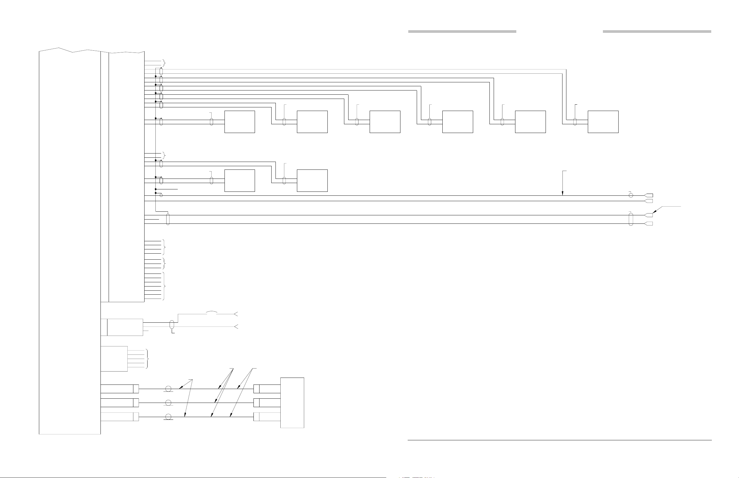
Preliminary
P/O P/ O
J1 P1
A429RX8_A
A429RX8_B
A429RX7_A
A42RRX7_B
A429RX5_A
A429RX5_B
A429RX4_A
A42RRX4_B
A429RX3_A
A429RX3_B
A429RX2_A
A429RX2_B
A429RX1_A
A429RX1_B
SKY899
Installation Manual
81
82
83
84
75
76
73
74
64
65
62
63
54
55
SEE NOTE 4
TP
TP
TP
TP
TP
TP
SEE NOTE 2
OPTIONAL
ARINC 429
XMIT
(SEE NOTES 5
AND 10)
SEE NOTE 2 SEE NOTE 2 SEE NOTE 2 SEE NOTE 2 SEE NOTE 2
OPTIONAL
ARINC 429
XMIT
(SEE NOTES 5
AND 10)
OPTIONAL
ARINC 429
XMIT
(SEE NOTES 5
AND 11)
OPTIONAL
ARINC 429
XMIT
(SEE NOTES 5
AND 11)
OPTIONAL
ARINC 429
XMIT
(SEE NOTE 5)
OPTIONAL
XPDR
ARINC 429
XT BUS
(SEE NOTE 4)
TRANSMITTER
RECEIVER
COMPUTER
UNIT
TRC899
A429TX3_A
A429TX3_B
A429TX2_A
A429TX2_B
A429TX1_A
A429TX1_B
RS422_TXA
RS422_TXB
RS422_RXA
RS422_RXB
RS232_TX2
RS232_RX2
RS232_GND2
ASU_MODE
ASU_SEL_ACK
ASU_MOD_ACK
J8 P8
SUPBUS
GPWS
AUDIO_H
AUDIO_L
AUDIO_C
+5V
-15V
ASU_SEL
ASU_GND
+28V
+28V_RET
SPARE
52
53
44
45
42
43
93
34
89
90
91
77
78
79
80
86
87
88
1
3
94
95
96
97
98
A
B
C
SEE NOTE 4
TP
TP
TP
SEE NOTE 4
SEE NOTE 4
SEE NOTE 4
SEE NOTE 6
16 AWG
16 AWG
SEE NOTE 2
SEE NOTE 2
SEE NOTE 2
OPTIONAL
EXTERNAL
ARINC 429
DISPLAY
F3
AIRCRAFT POWER
5A
(18 - 32VDC)
AIRCRAFT POWER RETURN
OPTIONAL
XPDR
ARINC 429
TX BUS
(SEE NOTE 4)
CAUTION:
THE AIRCRAFT TRANSPONDER MUST
HAVE SHIELDED SUPPRESSION CIRCUITRY
TO ENSURE THAT SKYWATCH DOES NOT
DISPLAY ITSELF AS ATARGET (TA).
SEE NOTE 6
SEE NOTE 6
SUPPRESSION I/O
GPWSFLAG
SEE NOTE 8
AUDIO HIGH
AUDIO COMMON
J7
DIAG_GND
DIAG_RX
DIAG_TX
CTS
RTS
J9
SUM
(BLUE)
J10
BIT_PROBE
J11
DIFFERENCE
(RED)
5
2
3
7
8
P9
P10
P11
DEBUG PORT
TEST ONLY
TYPE TNC
CONNECTOR
TYPE BNC
CONNECTOR
TYPE TNC
CONNECTOR
SEE NOTE 3
SEE NOTE 7
TNC
BNC
TNC
SEE NOTE 3
P3
SUM
P2
BIT_PROBE
P1
DIFFERENCE
NY164/NY156
DIRECTIONAL
ANTENNA
BLUE BAND
RED BAND
Figure 2-2. Interconnect Wiring Without WX-1000
(Sheet 2 of 2)
2-5 (page 2-6 blank)
Rev. A
Page 39
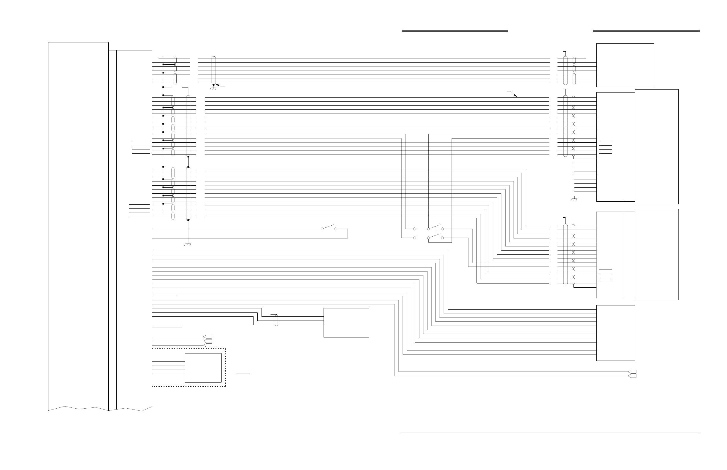
Preliminary
TRANSMITTER
RECEIVER
COMPUTER
UNIT
TRC899
P/O
J1
P/O
P1
HEADING_FLG
HEADING_C
HEADING_H
HEADING_Z
HEADING_Y
HEADING_X
DPWR+15_OUT
DPWR-15_OUT
DSPLY_GND_OUT
HSYNC_OUT+
HSYNC_OUT-
VSYNC_OUT+
VSYNC_OUTVIDEO_OUT+
VIDEO_OUT-
ON/OFF
ON/OFF_RET
SFTKEY1_IN
SFTKEY2_IN
SFTKEY3_IN
SFTKEY4_IN
DPWR+15_IN
DPWR-15_IN
DSPLY_GND_IN
HSYNC_IN+
HSYNC_IN-
VSYNC_IN+
VSYNC_INVIDEO_IN+
VIDEO_INSFTKEY1_OUT
SFTKEY2_OUT
SFTKEY3_OUT
SFTKEY4_OUT
SMS
SMS_RET
ALT_A1
ALT_A2
ALT_A4
ALT_B1
ALT_B2
ALT_B4
ALT_C1
ALT_C2
ALT_C4
ALT_D2
ALT_D4
ALT_COMN
SQUAT
GEAR
RAD_ALT_IN_HI
RAD_ALT_IN_LO
RADIO_ALT_FLG
DISCRETE
OPER_MODE
LP1OUT
LP2OUT
3.3V
PLUG_GND
SDA
SCL
51
50
49
48
47
46
8
9
10
11
12
13
22
16
17
4
5
18
19
20
21
25
26
27
28
29
30
41
35
36
37
38
39
40
15
23
56
57
58
59
60
61
67
68
69
70
71
72
24
33
6
7
14
32
31
66
85
2
92
99
100
N/C
TP
TP
SEE
NOTE 6
TP
TP
TP
TP
TP
TP
TP
TP BLK
TP
SEE NOTE 13
ORN
BLU
WHT
WHT
BLU
ORN
RED
GRN
BLKTP
YEL
WHT
BLUTP
ORN
RED
YEL
N/C
PERSONALITY PLUG
3.3V
PLUG_GND
SDA
SCL
BLU
WHT
BLU
WHT
BLU
ORN
WHT
WHT
ORN
BLU
WHT
BLU
WHT
BLU
WHT
BLU
WHT
BLU
WHT
BLU
WHT
BLU
WHT
ORN
BLU
WHT
BLU
WHT
BLU
WHT
BLU
WHT
BLU
WHT
BLU
DISCRETE I/O SEE NOTE 4
LAMP, SEE NOTE 16
LAMP ABV
LAMP BLW
HEADING INPUT CABLE
SEE NOTE 6
SW1
HIGH
LOW
VAL ID F LAG
RADIO ALT
SEE NOTE 9
STORMSCOPE
DC ANALOG ALT
}
SEE NOTE 12
}
INSIDE
CONNECTOR
BACKSHELL
SKYWATCH
TP
NOTES:
1.) ALL WIRES TO BE 22 AWG EXCEPT WHERE NOTED.
2.) TP - USE TWISTED SHIELDED PAIR CABLE.TERMINATE SHIELD TO AIRFRAME
GROUND AT SENSOR (OR POWER SOURCE).
3.) THE SUM CABLE WILL HAVE A BLUE BAND AT EACH END. THE DIFFERENCE CABLE
WILL HAVE A RED BAND AT EACH END.
4.) FUTURE OPTION.
5.) A RADIO ALTIMETER, AIRDATA COMPUTER, OR OTHER ARINC 429 OUTPUT
DEVICE MAY REPLACE ANALOG SENSORS FOR MAGNETIC HEADING, RADIO
ALTITUDE, OR BAROMETRIC ALTITUDE.
6.) TIE THE OUTER SHIELD TO THE CONNECTOR BACKSHELL. CONNECTOR BACKSHELL
IS CHASSIS GROUND.
7.) REFER TO INSTALLATION INSTRUCTIONS FOR CABLE SELECTION ON ANTENNA CABLES.
8.) USE AUDIO_H FOR 600 OHM AUDIO SYSTEMS. USE AUDIO_L FOR 150 OHM AUDIO
SYSTEMS.
Installation Manual
DISPLAY CABLE
OVER-RIDE
SW2
9.) DO NOT INSTALL EXTERNAL ISOLATION DIODES.
10.) THESE TWO DEVICES MUST BOTH BE HIGH SPEED OR BOTH BE LOW SPEED.
11.) THESE TWO DEVICES MUST BOTH BE HIGH SPEED OR BOTH BE LOW SPEED.
12.) ONLY USED WITH EXTERNAL DISPLAYS THAT DO NOT ANNUNCIATE ABOVE AND BELOW.
13.) IF D2 IS NOT USED THEN IT IS A "NO CONNECT" (N/C).
14.) IF THE SKYWATCH IS BEING INSTALLEDTO AN EXISTING WX-1000 SYSTEM, THE
CABLE GROUND AT THE WX-1000 DISPLAY AND THE WX-1000 PROCESSOR MUST
BE CHANGED FROM AS SHOWN IN THE WX-1000 MANUAL TO BE AS SHOWN HERE.
15.) INSTALLATION INSTRUCTIONS FOR THEWX-1000 ARE DETAILED IN THE
16.) OPTI ONAL, MAY BE USED TO DRIVE INDICATOR DEPICTING OPERATIONAL MODE.
NORMAL
SKY899
SEE NOTE 6
BLU
WHT
BLU
WHT
BLU
ORN
WHT
SEE NOTE 6
AND NOTE 14
WHT
ORN
BLU
WHT
BLU
WHT
BLU
WHT
BLU
WHT
BLU
WHT
BLU
WHT
BLU
SEE NOTE 6
AND NOTE 14
WHT
ORN
BLU
WHT
BLU
WHT
BLU
WHT
BLU
WHT
BLU
WHT
BLU
WHT
BLU
N/C
N/C
N/C
N/C
N/C
N/C
N/C
N/C
ORN
BLU
WHT
WHT
BLU
ORN
RED
GRN
BLK
YEL
WHT
BLU
ORN
RED
GRN
BLK
YEL
DIRECTIONAL GYRO COMPASS
N/C
HEADING VALID
LOW
}
HIGH
Z
HEADING
Y
}
X
P101 J101
19
+15
14
-15
18
DSPGND
6
HSYNCHI
5
HSYNCLO
9
VSYNCHI
10
VSYNCLO
8
VIDEOHI
7
VIDEOLO
22
PWRSWHI
23
PWRSWLO
13
SFTKEY1
12
SFTKEY2
25
SFTKEY3
24
SFTKEY4
2
SHIELD
1
GND
11
N/C
17
GND
15
-15V
16
GND
20
+15V
4
GND
3
GND
21
CHASSIS
P301 J301
3
+15
36
-15
38
DSPGND
6
HSYNCHI
23
HSYNCLO
40
VSYNCHI
7
VSYNCLO
39
VIDEOHI
22
VIDEOLO
21
PWRSWHI
20
PWRSWLO
9
SFTKEY1
26
SFTKEY2
43
SFTKEY3
44
SFTKEY4
5
SHIELD
A1
A2
A4
B1
B2
B4
C1
C2
C4
D2
D4
ALT_COMMON
SEE NOTE 9
SEE NOTE 9
26 VAC REFERENCE
ALTITUDE
DIGITIZER
WX-1000
DISPLAY
WX-1000
PROCESSOR
SEE NOTE 15
SQUAT SWITCH
LANDING GEAR POSITION
Figure 2-3. Interconnect Wiring With WX-1000
(Sheet 1 of 2)
2-7 (page 2-8 blank)
Rev. A
Page 40
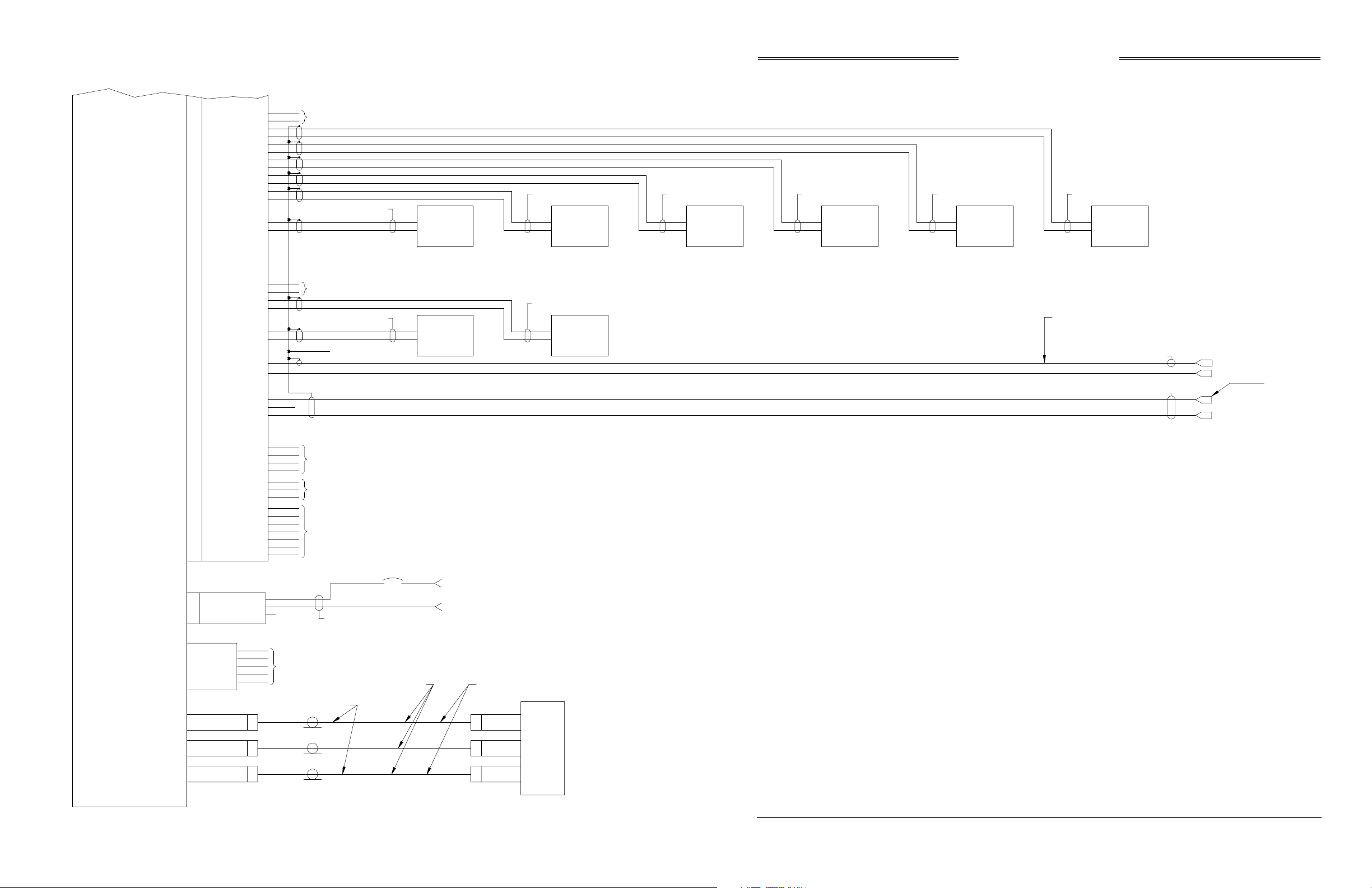
Preliminary
P/O P/ O
J1 P1
A429RX8_A
A429RX8_B
A429RX7_A
A42RRX7_B
A429RX5_A
A429RX5_B
A429RX4_A
A42RRX4_B
A429RX3_A
A429RX3_B
A429RX2_A
A429RX2_B
A429RX1_A
A429RX1_B
SKY899
Installation Manual
81
82
83
84
75
76
73
74
64
65
62
63
54
55
SEE NOTE 4
TP
TP
TP
TP
TP
TP
SEE NOTE 2
OPTIONAL
ARINC 429
XMIT
(SEE NOTES 5
AND 10)
SEE NOTE 2 SEE NOTE 2 SEE NOTE 2 SEE NOTE 2 SEE NOTE 2
OPTIONAL
ARINC 429
XMIT
(SEE NOTES 5
AND 10)
OPTIONAL
ARINC 429
XMIT
(SEE NOTES 5
AND 11)
OPTIONAL
ARINC 429
XMIT
(SEE NOTES 5
AND 11)
OPTIONAL
ARINC 429
XMIT
(SEE NOTE 5)
OPTIONAL
XPDR
ARINC 429
XT BUS
(SEE NOTE 4)
TRANSMITTER
RECEIVER
COMPUTER
UNIT
TRC899
A429TX3_A
A429TX3_B
A429TX2_A
A429TX2_B
A429TX1_A
A429TX1_B
RS422_TXA
RS422_TXB
RS422_RXA
RS422_RXB
RS232_TX2
RS232_RX2
RS232_GND2
ASU_MODE
ASU_SEL_ACK
ASU_MOD_ACK
J8 P8
SUPBUS
GPWS
AUDIO_H
AUDIO_L
AUDIO_C
+5V
-15V
ASU_SEL
ASU_GND
+28V
+28V_RET
SPARE
52
53
44
45
42
43
93
34
89
90
91
77
78
79
80
86
87
88
1
3
94
95
96
97
98
A
B
C
SEE NOTE 4
TP
TP
TP
SEE NOTE 4
SEE NOTE 4
SEE NOTE 4
SEE NOTE 6
16 AWG
16 AWG
SEE NOTE 2
SEE NOTE 2
SEE NOTE 2
OPTIONAL
EXTERNAL
ARINC 429
DISPLAY
F3
AIRCRAFT POWER
5A
(18 - 32VDC)
AIRCRAFT POWER RETURN
OPTIONAL
XPDR
ARINC 429
TX BUS
(SEE NOTE 4)
CAUTION:
THE AIRCRAFT TRANSPONDER MUST
HAVE SHIELDED SUPPRESSION CIRCUITRY
TO ENSURE THAT SKYWATCH DOES NOT
DISPLAY ITSELF AS ATARGET (TA).
SEE NOTE 6
SEE NOTE 6
SUPPRESSION I/O
GPWSFLAG
SEE NOTE 8
AUDIO HIGH
AUDIO COMMON
J7
DIAG_GND
DIAG_RX
DIAG_TX
CTS
RTS
J9
SUM
(BLUE)
J10
BIT_PROBE
J11
DIFFERENCE
(RED)
5
2
3
7
8
P9
P10
P11
DEBUG PORT
TEST ONLY
TYPE TNC
CONNECTOR
TYPE BNC
CONNECTOR
TYPE TNC
CONNECTOR
SEE NOTE 3
SEE NOTE 7
TNC
BNC
TNC
SEE NOTE 3
P3
SUM
P2
BIT_PROBE
P1
DIFFERENCE
NY164/NY156
DIRECTIONAL
ANTENNA
BLUE BAND
RED BAND
Figure 2-3. Interconnect Wiring With WX-1000
(Sheet 2 of 2)
2-9 (page 2-10 blank)
Rev. A
Page 41
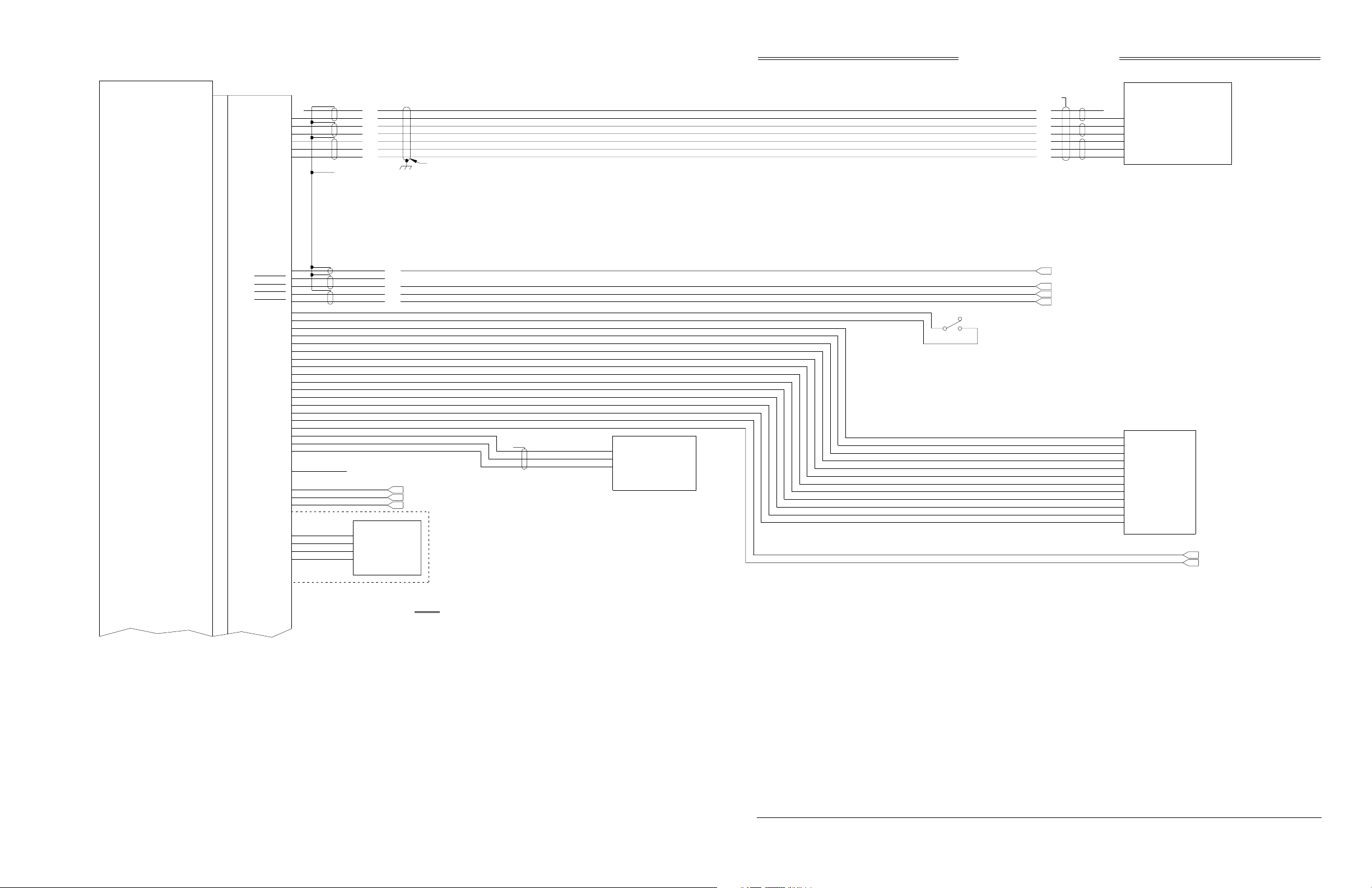
Preliminary
TRANSMITTER
RECEIVER
COMPUTER
UNIT
P/O P/O
J1 P1
HEADING_FLG
HEADING_C
HEADING_H
HEADING_Z
HEADING_Y
HEADING_X
SKY899
Installation Manual
N/C
TP
51
50
TP
49
48
47
46
ORN
BLU
WHT
SEE NOTE 6
BLU
WHT
BLU
WHT
BLU
ORN
WHT
HEADING INPUT CABLE
SEE NOTE 6
SEE NOTE 6
BLU
WHT
BLU
WHT
BLU
ORN
WHT
ORN
BLU
WHT
DIRECTIONAL GYRO COMPASS
N/C
HEADING VALID
LOW
}
HIGH
Z
Y
}
X
SEE NOTE 9
26 VAC REFERENCE
HEADING
TRC899
DSPLY_GND_OUT
SFTKEY1_IN
SFTKEY2_IN
SFTKEY3_IN
SFTKEY4_IN
ON/OFF
ON/OFF_RET
ALT_A1
ALT_A2
ALT_A4
ALT_B1
ALT_B2
ALT_B4
ALT_C1
ALT_C2
ALT_C4
ALT_D2
ALT_D4
ALT_COMN
SQUAT
GEAR
RAD_ALT_IN_HI
RAD_ALT_IN_LO
RADIO_ALT_FLG
DISCRETE
OPER_MODE
LP1OUT
LP2OUT
3.3V
PLUG_GND
SDA
SCL
10
18
19
20
21
4
5
56
57
58
59
60
61
67
68
69
70
71
72
24
33
6
7
14
32
31
66
85
2
92
99
100
BLKTP
YEL
TP
SEE NOTE 13
BLU
N/C
BLU
WHT
BLU
DISCRETE I/O SEE NOTE 4
N/C
PERSONALITY PLUG
3.3V
PLUG_GND
SDA
SCL
LAMP, SEE NOTE 14
LAMP ABV
LAMP BLW
SEE NOTE 12
}
INSIDE
CONNECTOR
BACKSHELL
DISPLAY_GND_OUT
TEST/ALT
RANGE
"OFF"
"ON" 3A @ 28VDC
TP
HIGH
}
LOW
VAL ID F LAG
RADIO ALT
SEE NOTE 9
DC ANALOG ALT
STBY/OPER
A1
A2
ALTITUDE
A4
DIGITIZER
B1
B2
B4
C1
SEE NOTE 9
C2
C4
D2
D4
ALT_COMMON
SQUAT SWITCH
LANDING GEAR POSITION
NOTES:
1.) ALL WIRES TO BE 22 AWG EXCEPT WHERE NOTED.
2.) TP - USE TWISTED SHIELDED PAIR CABLE. TERMINATE SHIELD TO AIRFRAME GROUND AT SENSOR (OR POWER SOURCE).
3.) THE SUM CABLE WILL HAVE A BLUE BAND AT EACH END.THE DI FFERENCE CABLE WILL HAVE A RED BAND AT EACH END.
4.) FUTURE OPTION.
5.) A RADIO ALTIMETER, AIRDATA COMPUTER, OR OTHER ARINC 429 OUTPUT DEVICE MAY REPLACE ANALOG SENSORS FOR
MAGNETIC HEADING, RADIO ALTITUDE, OR BAROMETRIC ALTITUDE.
6.) TIE THE OUTER SHIELD TO THE CONNECTOR BACKSHELL. CONNECTOR BACKSHELL IS CHASSIS GROUND.
7.) REFER TO INSTALLATION INSTRUCTIONS FOR CABLE SELECTION ON ANTENNA CABLES.
8.) USE AUDIO_H FOR 600 OHM AUDIO SYSTEMS. USE AUDIO_L FOR 150 OHM AUDIO SYSTEMS.
9.) DO NOT INSTALL EXTERNAL ISOLATION DIODES.
10.) THESE TWO DEVICES MUST BOTH BE HIGH SPEED OR BOTH BE LOW SPEED.
11.) THESE TWO DEVICES MUST BOTH BE HIGH SPEED OR BOTH BE LOW SPEED.
12.) ONLY USED WITH EXTERNAL DISPLAYS THAT DO NOT ANNUNCIATE ABOVE AND BELOW.
13.) IF D2 IS NOT USEDTHEN IT IS A "NO CONNECT" (N/C).
14.) OPTIONAL, MAY BE USED TO DRIVE INDICATOR DEPICTING OPERATIONAL MODE.
Figure 2-4. Interconnect Wiring with
Alternate Display (Sheet 1 of 2)
2-11 (page 2-12 blank)
Rev. A
Page 42
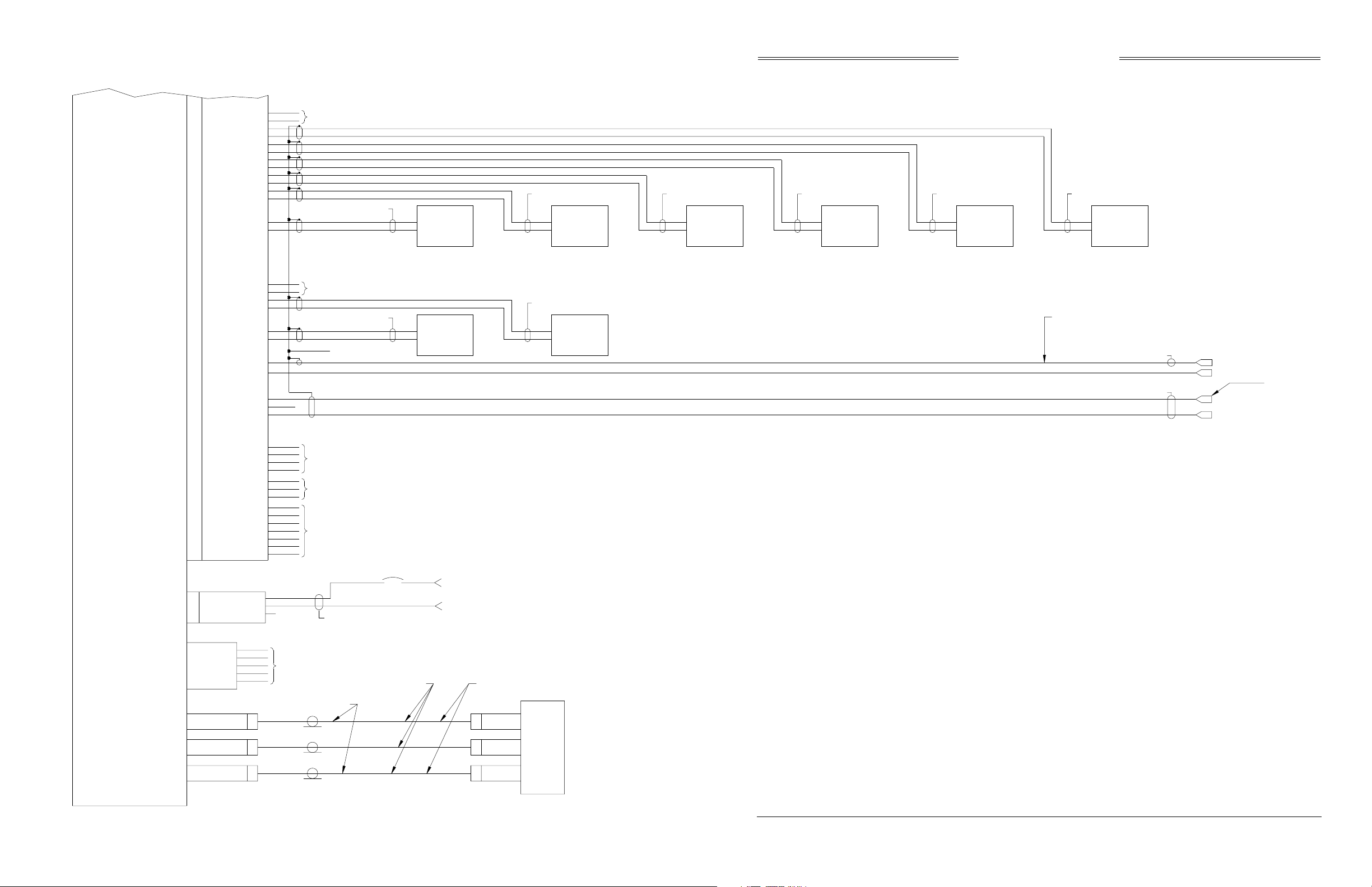
Preliminary
P/O P/ O
J1 P1
SKY899
Installation Manual
TRANSMITTER
RECEIVER
COMPUTER
UNIT
A429RX8_A
A429RX8_B
A429RX7_A
A42RRX7_B
A429RX5_A
A429RX5_B
A429RX4_A
A42RRX4_B
A429RX3_A
A429RX3_B
A429RX2_A
A429RX2_B
A429RX1_A
A429RX1_B
A429TX3_A
A429TX3_B
A429TX2_A
A429TX2_B
A429TX1_A
A429TX1_B
SUPBUS
GPWS
AUDIO_H
AUDIO_L
AUDIO_C
81
82
83
84
75
76
73
74
64
65
62
63
54
55
52
53
44
45
42
43
93
34
89
90
91
SEE NOTE 4
TP
TP
TP
TP
TP
TP
SEE NOTE 4
TP
TP
TP
SEE NOTE 2
SEE NOTE 2
SEE NOTE 6
OPTIONAL
ARINC 429
XMIT
(SEE NOTES 5
AND 10)
EXTERNAL
ARINC 429
DISPLAY
SEE NOTE 2 SEE NOTE 2 SEE NOTE 2 SEE NOTE 2 SEE NOTE 2
OPTIONAL
ARINC 429
XMIT
(SEE NOTES 5
AND 10)
SEE NOTE 2
OPTIONAL
XPDR
ARINC 429
TX BUS
(SEE NOTE 4)
OPTIONAL
ARINC 429
XMIT
(SEE NOTES 5
AND 11)
OPTIONAL
ARINC 429
XMIT
(SEE NOTES 5
AND 11)
OPTIONAL
ARINC 429
XMIT
(SEE NOTE 5)
CAUTION:
OPTIONAL
XPDR
ARINC 429
XT BUS
(SEE NOTE 4)
THE AIRCRAFT TRANSPONDER MUST
HAVE SHIELDED SUPPRESSION CIRCUITRY
TO ENSURE THAT SKYWATCH DOES NOT
DISPLAY ITSELF AS ATARGET (TA).
SEE NOTE 6
SEE NOTE 6
SUPPRESSION I/O
GPWSFLAG
SEE NOTE 8
AUDIO HIGH
AUDIO COMMON
TRC899
RS422_TXA
RS422_TXB
RS422_RXA
RS422_RXB
RS232_TX2
RS232_RX2
RS232_GND2
ASU_MODE
ASU_SEL_ACK
ASU_MOD_ACK
J8 P8
+28V_RET
J7
DIAG_GND
DIAG_RX
DIAG_TX
CTS
RTS
J9
SUM
(BLUE)
J10
BIT_PROBE
J11
DIFFERENCE
(RED)
+5V
-15V
ASU_SEL
ASU_GND
+28V
SPARE
5
2
3
7
8
P9
P10
P11
77
78
79
80
86
87
88
1
3
94
95
96
97
98
A
B
C
DEBUG PORT
TEST ONLY
TYPE TNC
CONNECTOR
TYPE BNC
CONNECTOR
TYPE TNC
CONNECTOR
SEE NOTE 4
SEE NOTE 4
SEE NOTE 4
SEE NOTE 2
SEE NOTE 3
16 AWG
16 AWG
F3
5A
SEE NOTE 7
AIRCRAFT POWER
(18 - 32VDC)
AIRCRAFT POWER RETURN
SEE NOTE 3
P3
SUM
TNC
P2
BIT_PROBE
BNC
P1
DIFFERENCE
TNC
NY164/NY156
DIRECTIONAL
ANTENNA
BLUE BAND
RED BAND
Figure 2-4. Interconnect Wiring with
Alternate Display (Sheet 2 of 2)
2-13 (page 2-14 blank)
Rev. A
Page 43

Preliminary
SKY899
Installation Manual
2.5 DISPLAY LOCATION
The display should be mounted in a location easily accessible and clearly visible to the pilot. If using an
alternate display device refer to manufacturer instructions for location. In selecting a location for WX1000/SKY497 display, consider the following:
Magnetic Effect Where possible to avoid it, the display should not be mounted within
3 inches (8 cm) of an electric turn and bank indicator, as the magnetic
effect of the turn and bank motor may affect the display presentation. (A
common symptom of magnetic interference is a wobbling or vibrating
display raster.)
NOTE
If it is necessary to mount the display unit next to a device that may affect
the CRT display, magnetic shielding material can be placed around the
display unit. Shielding material is available from BFG Avionics Systems.
Specify P/N 78-8060-5882-8 when ordering.
Panel Depth Adequate depth must be available behind the instrument panel to allow for
the display, the display connector, and excess display cable. Remember
that a service loop is necessary to allow access to the display connector
when removing the display or inserting it into the instrument panel.
Cooling While the display has no special cooling requirements, it should be
mounted to permit adequate ventilation.
Viewing Angle The viewing angle for the CRT display is not a critical factor. The most
favorable mounting position would be near eye level and no more than
arms length from the principle user of the instrument.
2-15
Rev. A
Page 44

Preliminary
SKY899
Installation Manual
2.6 CABLE REQUIREMENTS AND FABRICATION
The installer will supply and fabricate all system cables. Cable specifications and approved vendors are
provided in paragraph 1.7, equipment required but not supplied. Appendix A defines the electrical
characteristics of all input and output signals and identifies the cable requirements for each signal.
Required connectors and contact pins are supplied in the installation kits.
NOTES
1. Use of any cable not meeting BFG Avionics Systems specifications voids
all system warranties.
2. All wiring must be in accordance with industry accepted methods,
techniques and practices.
3. All wires are 22 AWG. except where noted, refer to figures 2-2, 2-3 and
2-4 for interconnect wiring information.
The length and routing of the external cables must be carefully studied and planned before attempting
installation of the equipment. Observe the following precautions:
• ARINC-429 inputs (receive channels) must be paired with other ARINC-429 inputs of the same
speed (12.5 or 100 kHz). Details are outlined in paragraph 2.9.
• All cable routing should be kept as short and direct as possible.
• Avoid routing the cables too close to aircraft control cables.
• Avoid routing cable near the ADF, comm radio, or transponder antenna cables (allow at least a 12
inch (30.5 cm) separation).
• Avoid routing cable near power sources (e.g., 400 Hz generators, trim motors, etc.) and near power
for fluorescent lighting.
• Use pressurized bulkhead connectors certified for your specific aircraft pressurization.
• To limit the possibility of wire chafing, it is recommended that heat shrink sleeving be installed
over the wire bundle between the shield termination’s (inside the connector backshell) and the
connector cable clamp.
• Observe all wiring notes on interconnect wiring diagram (figures 2-2, 2-3 and 2-4).
After fabricating the cables and before installing the equipment, use the interconnect diagram to verify
continuity between each pin and its opposite end termination. Check resistance to ground between each
connector pin. When a path to ground is detected, verify its validity. Figure A-1 P1 connector pin
identifiers has been added to assist in fabrication and continuity verification of the interconnect cable.
2-16
Rev. A
Page 45

Preliminary
SKY899
Installation Manual
2.6.1 Antenna Cables
NOTES
1. Use of any cable not meeting BFGoodrich Avionics Systems specifications
voids all system warranties.
2. If you fabricate your own cables, you must verify that the attenuation and
VSWR does not exceed the specified values.
3. To add strain relief and alleviate stress caused by aircraft vibration, place 46 inches (10.2 to 15.2 cm) of heat shrink tubing over each antenna connector
and cable.
The directional antenna requires three cable assemblies; sum (Sigma Port), bit probe (Probe Port) and
difference (Delta Port). Cable attenuation for the sum and difference ports must not exceed 2.5 dB.
Attenuation for the bit probe cable must not exceed 6 dB. VSWR, on cables attached to the sum, bit probe,
and difference ports, must not exceed 1.5:1. (See paragraph 1.7 for antenna cable vendors and
specifications.)
At the antenna, each connector has an identifying color band. To ensure the cables are connected to the
correct port, affix the following marking at the termination points of each cable:
Sum (Sigma) Port The Sum (Sigma) port is the forward antenna connector. It is marked with
a blue band. Fabricate the sum antenna cable with a TNC connector at
each end. Affix a blue marking band on each connector. At the TRC, the
sum port (J9) is identified with blue marking.
Bit Probe Port The Bit Probe port is the center antenna connector. Fabricate the probe
cable with a BNC connector at each end.
Difference (Delta) Port The Difference (Delta) port is the rear antenna connector. It is marked with
a red band. Fabricate the difference antenna cable with a TNC connector at
each end. Affix red marking band on each connector. At the TRC, the
difference port (J11) is identified with red marking.
When routing antenna cables, observe the following precautions:
• All cable routing should be kept as short (do not exceed maximum cable length detailed in table 1-
6) and direct as possible.
• Avoid sharp bends (do not exceed maximum bend radius detailed in table 1-6).
• Avoid routing cable near power sources (e.g., 400 Hz generators, trim motors, etc.) and near power
for fluorescent lighting.
• Avoid routing cable near ADF antenna cable (allow at least a 12-inch (30.5) separation).
2.6.2 Audio Output Cable
For audio output cable use #22 AWG (minimum) twisted shielded pairs with the shield grounded at both
ends. Cable runs can be up to 30 ft., but should be as short as practicable.
2.6.3 Data Cables
RS-232, RS-422, and ARINC-429 data cables are #22 AWG (minimum) twisted, shielded cables. The shield
shall be grounded at both ends and at all breaks. Cable runs should be as short as practicable.
2-17
Rev. A
Page 46
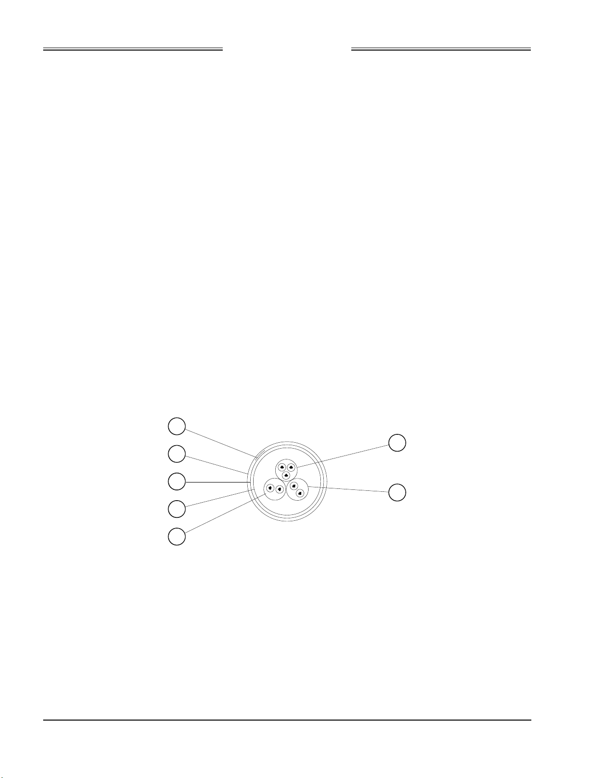
Preliminary
SKY899
Installation Manual
2.6.4 Heading Input Cable
The heading input cable connects the TRC899 to the aircraft synchro heading system (refer to the
Interconnect Wiring Diagram, figure 2-2, 2-3 or 2-4). Cable specifications are listed below (see paragraph
1.7 for cable vendors).
NOTE
Use of any cable not meeting BFG Avionics Systems specifications voids all
system warranties.
The synchro cable consists of the following (refer to figure 2-5):
1. Twisted, Shielded, Jacketed Triad #24 AWG
Colors: White, Blue, Orange
Shield: Tin Plated Copper Braid, 90% min.
Jacket: FEP .007 in. min., White
2. Twisted, Shielded, Jacketed Pair #24 AWG
Colors: White, Blue
Shield: Tin Plated Copper Braid, 90% min.
Jacket: FEP .007 in. min., Blue
3. Same as Item 2, except Orange jacket.
4. Aluminized Mylar® Wrap.
5. #34 AWG braided shield.
6. FEP Teflon® jacket .013 in. - .023 in., clear (translucent).
7. Marker tape with vendor P/N.
The sub-cable color-coded jackets and shields should be left on the sub-cables as close to the connector as
practical to provide the required shielding and to identify the sub-cables.
7
1
6
5
2
4
3
Figure 2-5. Heading Input Cable
2.6.5 Power Cable
For the power cable, use #16 AWG (minimum) twisted shielded pair cable (Beldon 83322, Alpha 2826/2, or
equivalent). The power cable runs from the aircraft circuit breaker panel to the TRC. The power cable is
connected to the TRC using the MS3126F12-3S connector included in the TRC installation kit. Terminate
the shield to airframe ground at the power source. Power cable routing and length are not critical to
system operation. The SKY899 is a 28 V dc system (18 to 32 V dc).
NOTE
5 A circuit breaker is required.
2-18
Rev. A
Page 47

Preliminary
SKY899
Installation Manual
2.6.6 Suppression Bus Cable
For the suppression bus use any size low capacitance shielded cable. Cable runs should be as short as
practicable and the shields should be grounded at both ends.
2.6.7 WX-1000/SKY497 Display and WX-1000 Processor Cable
The display cable connects the TRC to the WX-1000/SKY497 Display. Cable specifications are listed below
(see paragraph 1.7 for cable vendors). If a WX-1000 Stormscope® Weather Mapping System is installed,
the same cable is used to connect the TRC to a WX-1000 processor. Refer to figure 2-2 (without WX-1000
processor) or 2-3 (with WX-1000 processor) for interconnect wiring information. Pin-out information
relating to the WX-1000 display and processor is also provided in tables 2-2 and 2-3.
For alternate display device cable see ARINC-429 data cable (par. 2.6.3) and refer to figure 2-4 for
connections.
The display cable consists of the following (refer to figure 2-6).
1. Twisted, shielded, jacketed triad #22 AWG
Colors: White, Blue, Orange
Shield: Tin plated copper braid, 90% min.
Jacket: FEP .007 in. min., White jacket
2. Twisted, shielded, jacketed pair #24 AWG
Colors: White, Blue
Shield: Tin plated copper braid, 90% min.
Jacket: FEP .007 in. min., Blue jacket
3. Same as 2 except Orange jacket.
4. Same as 2 except Green jacket.
5. Same as 2 except Red jacket.
6. Same as 2 except Black jacket.
7. Same as 2 except Yellow jacket.
8. Aluminized Mylar® wrap.
9. #34 AWG braided shield.
10. FEP Teflon® jacket .013 in. - .023 in., Red tint.
11. Marker tape with Vendor P/N.
2-19
Rev. A
Page 48
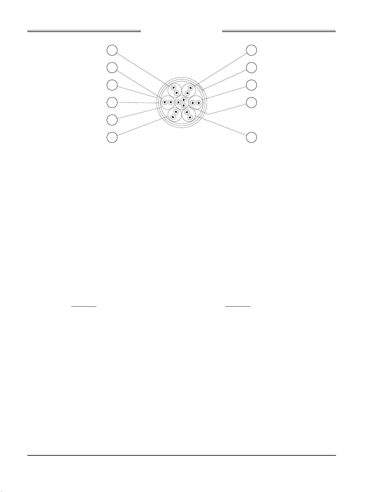
Preliminary
SKY899
Installation Manual
7
6
10
9
8
5
Figure 2-6. Display Cable
The sub-cable color-coded jackets and shields should be left on the sub-cables as close to the connectors as
practical to provide the required shielding and to identify the sub-cables.
2.6.8 Converting Existing Aircraft Wiring from SKY497 to SKY899
In some instances, it may be desirable to convert an existing SKY497 installation to a SKY899
installation. The SKY899 is a new system with the addition of a system configuration module and a new
TRC899. Even though the TRC899 resembles a TRC497, uses the same antenna and mounting hardware,
the external connector P1 has different pinouts and is keyed differently to prevent the possibility of
damaging a TRC. In order to relocate pin positions use the insertion and extraction tools listed in
paragraph 1.7, under sub title "Connector Installation."
2
11
3
1
4
All P1 connections will need to be moved from an existing pin location to a
new pin location, as well as the addition of the system configuration module.
Only the power and antenna connections remain the same.
Some of the differences:
TRC899
• 7 ARINC-429 RX channels
• 3 ARINC-429 TX channels
• System Configuration Module
(configure system in service menu)
• Heading valid, 1 input pin
(low/high level selected in service menu)
• Analog radio altimeter
• 18 - 32 V dc power input
• ADS-B (requires mode S transponder address)
• Altimeter Gilham Code "D2" added
(do not connect if not available)
• Lamp Outputs - above, below and oper_mode
(used with alternate display)
• Transponder input/output
• Stepper (heading) not available
NOTE
TRC497
2 ARINC-429 RX channels
1 ARINC-429 TX channel
Individual configuration pins
Heading valid, 2 input pins (low or high level)
Not available
11 - 34 V dc power input
Not available
Altimeter Gilham Code "D2" not available
Not available
Not available
Stepper (heading) available
2-20
Rev. A
Page 49

Preliminary
SKY899
Installation Manual
2.7 AIRCRAFT DISCRETE INPUTS
The aircraft discrete inputs are used to assist in determining the aircraft's phase of flight or flight
condition (e.g., on ground or in flight). Inputs are diode isolated inside the TRC, do not install isolation
diodes externally. The active or inactive state of the inputs can be high or low, they will be saved in the
System Configuration Module during system setup using the service menu.
2.7.1 Audio Inhibit (Terrain Warning System - GPWS)
The audio inhibit input will sense a terrain warning alarm (i.e., GPWS, EGPWS, TAWS) and temporarily
disable the audio alert output until the terrain warning clears. The input can be either a constant flag
signal or an alternating flag output. The flag must be cleared for 5 seconds before the TRC accepts a “NO
ALARM” condition and restores audible alerts.
NOTES
1. If the aircraft is equipped with terrain warning system, it must be connected
to the TRC.
2. If the aircraft is not equipped with terrain warning system, leave this input
unconnected.
Audio inhibit connection:
GPWS P1-34
2.7.2 Landing Gear
This input is to be connected to the landing gear switch to sense the position of the landing gear (fixed, up
or down). The switch status of this input is selected during system setup via the service menu. This input
has three service menu options, none (fixed gear), active low (electrically ground with aircraft on the
ground) and active high (electrically high (+9 V to +28 V) with aircraft on the ground).
Landing gear connection:
GEAR P1-33
If the aircraft does not have a landing gear switch (e.g., fixed-gear aircraft), leave this input unconnected.
With this configuration, if a radio altimeter (analog or ARINC-429) is not installed, the system will default
to the highest TA sensitivity level (level B) and audio TA announcements (i.e., “traffic, traffic”) will not be
inhibited during takeoff and landing.
2.7.3 SKYWATCH/
The SKYWATCH/Stormscope mode switch (SW1) is required only if a WX-1000 Stormscope Weather
Mapping System is installed. This switch permits the flight crew to switch the display between the
SKY899 and WX-1000. If a TA (Traffic Advisory) is detected while in the Stormscope mode, the display will
switch to the SKYWATCH mode. Refer to figure 2-3 for interconnect wiring information. Any general
purpose SPST toggle switch (3 Amp @ 28 V dc) may be used. Display mode switch cable routing and length
are not critical to system operation. Mount the switch at a location easily accessible to the pilot.
SKYWATCH/Stormscope mode switch connections:
Stormscope
SMS P1-15
SMS_RET P1-23
Mode Switch
2.7.4 Squat Switch (Weight-On-Wheels)
This input is to be connected to the squat switch (weight-on-wheels) to sense when the aircraft is on the
ground. The switch status of this input is selected during system setup via the service menu. This input
has three service menu options, none (no squat switch installed), active low (electrically ground with
aircraft on the ground) and active high (electrically high (+9 V to +28 V) with aircraft on the ground).
Rev. A
2-21
Page 50

Preliminary
SKY899
Installation Manual
NOTE
If the aircraft is not equipped with a squat switch, it is recommended that a
squat switch be installed.
Squat switch connection:
SQUAT P1-24
If a squat switch is not available, this input could be tied to an airspeed switch inline with the pitot system
as an alternate input for the squat switch. In this configuration care should be taken to ensure the switch
is set to trigger at a speed consistent with take-off and landing.
On helicopter installations with skids, and a squat switch is not available, this input can be tied to the
collective switch. In this configuration care should be taken to ensure the switch is connected to provide a
ground when the aircraft is on the ground and open when the aircraft is airborne.
If it is not possible to install a squat switch, airspeed switch, or collective switch, select none in service
menu. With this configuration the pilot must toggle the system in and out of standby manually. Traffic
will only be displayed when the pilot switches out of the standby position.
With a squat switch installed, SKYWATCH HP will automatically switch out of standby 8 to 10 seconds
after takeoff and switch back to standby 24 seconds after landing. A squat switch would also prevent the
pilot from placing SKYWATCH HP in standby (i.e., pressing the →→→→STB button) while the aircraft is inflight.
ON/OFF
2.7.5
This input connection turns the TRC ON and OFF. Wiring of this input will vary depending upon your
specific installation. With pin P1-4 connected to P1-5 the system will turn on. There are three possible
configurations discussed below:
Alternate Display. A separate ON/OFF switch is required (any SPDT toggle switch rated at 3A @ 28 V dc
can be used). Refer to display manufactures instructions and figure 2-4 concerning this connection.
WX-1000/SKY497 Display (without WX-1000). Connect per figure 2-2.
Stormscope WX-1000 Installation. This external over-ride switch (SW2) is required if a WX-1000
Stormscope Weather Mapping System is installed. The override switch enables the SKYWATCH HP to be
powered-up if the WX-1000 processor has been removed for maintenance. During normal operation the
switch should remain in the NORMAL position and moved to OVERRIDE only if the WX-1000 processor
has been removed for service or if it is necessary to access the WX-1000 service menu. Connect per figure
2-3
Any general purpose DPDT toggle switch (3 Amp @ 28 V dc) may be used. The maintenance switch cable
routing and length are not critical to system operation. The switch can be located in the avionics bay near
the WX-1000 processor.
ON/OFF power switch connection:
2.8 ALTERNATE DISPLAY
Alternate display (ARINC-735 compatible is required for TCAS I installation) is connected to ARINC-429
output channel. Refer to paragraph 2.9 for ARINC-429 output channel information.
Power Switch
ON/OFF P1-4
ON/OFF_RET P1-5
2-22
Rev. A
Page 51

Preliminary
SKY899
Installation Manual
2.9 ARINC-429
The ARINC-429 interface can be divided into four sections: general sensor inputs, mode S transponder
input/output, alternate display output and future input/output options. The TRC has seven receive
channels and three transmit channels that are used to accomplish the various interfaces. However, two
receiver and two transmitter channels are not used at this time (future option). ARINC-429 labels
accepted and transmitted are listed in tables A-3 and A-4.
2.9.1 General Sensor Inputs
The TRC can use four general sensor inputs: barometric altimeter, radio altimeter, magnetic heading, and
GPS navigation data. Five receive channels have been designated for these inputs and will allow various
combinations of speed and equipment types. It is also possible for multiple data inputs (barometric
altimeter, radio altimeter, magnetic heading and GPS navigation) from one source to be received on one
channel (e.g., ARINC-429 superbus). Receiver speed and equipment type must be set via the service menu.
When planning the ARINC-429 interface note the following:
NOTES
1. The data rate for RX channels 1 and 2 must be set to the same speed
(12.5 or 100 kHz).
2. The data rate for RX channels 3 and 4 must be set to the same speed
(12.5 or 100 kHz).
3. The data rate for channel 5 is independent of the other receivers.
Channel 5 can be set to 12.5 or 100 kHz.
ARINC-429 General Sensor Input connections:
A429RX1_A (P1-54)
A429RX1_B (P1-55)
A429RX2_A (P1-62)
A429RX2_B (P1-63)
A429RX3_A (P1-64)
A429RX3_B (P1-65)
A429RX4_A (P1-73)
A429RX4_B (P1-74)
A429RX5_A (P1-75)
A429RX5_B (P1-76)
2.9.2 Mode S Transponder I/O (future option)
The TRC has one receive and one transmit channel designated for the mode S transponder XT & TX bus
interface. The receiver and transmit speed is fixed at 100 kHz. This is a future option, do not connect at
this time.
Mode S Transponder XT bus connections:
A429RX7_A (P1-83)
A429RX7_B (P1-84)
Mode S Transponder TX bus connections:
A429TX2_A (P1-44)
A429TX2_B (P1-45)
2-23
Rev. A
Page 52

Preliminary
SKY899
Installation Manual
2.9.3 Alternate Display Output
The TRC has one transmit channel designated for alternate displays (i.e., EFIS, MFD and weather radar
via RGC250). The transmitter speed is fixed at 100 kHz. The display driver must be selected via the
service menu. The display drivers control the ranges and information that will be presented on the
alternate display. The drivers are listed in table 2-1 along with their specifications.
NOTE
When an alternate display is selected via the service menu the alternate
display is the master display and the WX-1000/SKY497 display is the slave
(i.e., display range settings are controlled by the alternate display driver).
Alternate Display connections:
A429TX1_A (P1-42)
A429TX1_B (P1-43)
Table 2-1. Alternate Display Drivers
DISPLAY DRIVER NAME
DISPLAY
RANGES
STANDBY
RANGE
SELF-TEST
RANGE
REMARKS
None - - - No alternate display connected must use WX-
Standard Type 1 2, 6, 15 nmi 15 nmi 6 nmi
Standard Type 2 6, 12, 20 nmi 12 nmi 6 nmi
Standard Type 3 5, 10, 20 nmi 10 nmi 5 nmi
Sextant Type 1 6, 12, 24 nmi 12 nmi 6 nmi Displays unrestricted mode, must use external lamps to
Sextant Type 2 6, 12, 24 nmi 12 nmi 6 nmi Does not display unrestricted mode
Sextant CG 6, 12, 24 nmi 6 nmi 6 nmi Does not display unrestricted mode
Forestry Serv 2, 5, 10, 20 nmi 10 nmi 5 nmi
Collins EFIS Type 1 5, 10, 25 nmi 10 nmi 5 nmi Sends only 8 most threatening intruders to display.
2.9.4 Future Option
The TRC has one spare receiver A429RX8_A (P1-81) & A429RX8_B (P1-82) and one spare transmitter
A429TX3_A (P1-52) & A429TX3_B (P1-53) reserved for a future option. Do not connect these I/O channels.
2.10 AUDIO (ALERT) OUTPUT
Voice messages are output to the aircraft audio system, unless the audio inhibit input (from GPWS) is
active. The audio output is disabled when a terrain warning system (GPWS) alarm is detected and
remains disabled until the warning clears.
1000/SKY497 display.
annunciate UNR mode.
EFIS changes ranges internally.
Two outputs, 150 ohm and 600 ohm, can supply up to 40 mW to the audio distribution system. Volume
level is set via the Service Menu.
Audio output connections:
AUDIO_H P1-89 (600 Ohm)
AUDIO_L P1-90 (150 Ohm)
AUDIO_C P1-91 (Audio Common)
2-24
Rev. A
Page 53

Preliminary
SKY899
Installation Manual
2.11 BAROMETRIC (UNCORRECTED) ALTITUDE INPUTS
The TRC requires an uncorrected barometric altimeter input. The barometric altitude can be gilham code
or ARINC-429 (air data computer (ADC)).
NOTES
1. Only one uncorrected barometric altimeter input source, either gilham code,
ARINC-429 (ADC) should be connected.
2. The uncorrected barometric altimeter input (gilham code or ARINC-429) should
be from the same source that is interfaced with the transponder or it must be at
least as accurate as that source, i.e., ± 125 ft.
2.11.1 Gilham Code (Encoding Altimeter)
These signals are gilham code inputs coming from an airdata computer or altitude digitizer (encoding
altimeter). These 11 lines may be connected in parallel with the aircraft transponder. If the aircraft is
equipped with selectable altitude encoders, connect the altitude inputs so that SKY899 is always
connected to the selected encoder. (Reference ARINC 572-1.)
NOTE
If the aircraft has switched encoders that use 28V RETURN or AIRCRAFT
GROUND as reference for encoder selection, then ALTITUDE COMMON
should be left unconnected.
Altitude encoder connections:
A1 -to- P1-56 B1 -to- P1-59 C1 -to- P1-67 D2* -to- P1-70
A2 -to- P1-57 B2 -to- P1-60 C2 -to- P1-68 D4 -to- P1-71
A4 -to- P1-58 B4 -to- P1-61 C4 -to- P1-69
ALTITUDE COMMON - to P1-72
* If D2 is not used P1-70 should remain unconnected
2.11.2 ADC (ARINC-429)
ADC (ARINC-429) speed can be 12.5 or 100 kHz and must be paired with another input device set to the
same speed. Refer to paragraph 2.9 for ARINC-429 receiver channel information.
2.12 GPS (ARINC-429)
The GPS (ARINC-429) speed can be 12.5 or 100 kHz and must be paired with another input device set to
the same speed. Refer to paragraph 2.9 for ARINC-429 receiver channel information. In order to use
ADS-B, SKYWATCH HP requires a GPS input that is GAMA or ARINC-743A compliant.
2.13 HEADING INPUT
The magnetic heading can be provided by synchro (XYZ) or ARINC-429 (attitude heading and reference
system), depending on the configuration settings. Heading source will be selected during system setup via
the service menu. Select only one heading source for the input.
2.13.1 Compass Synchro (XYZ)
Synchro (XYZ) heading input accepts ARINC 407, 407-1 signals. The FLAG line input provides the TRC
with flag status (or heading valid) information. The status of the heading valid signal can be none, active
high, or active low (see appendix A for signal characteristics) and must be selected during system setup via
the service menu.
2-25
Rev. A
Page 54

Preliminary
SKY899
Installation Manual
Synchro (XYZ) heading connections:
HEADING_X P1-46 (Synchro X)
HEADING_Y P1-47 (Synchro Y)
HEADING_Z P1-48 (Synchro Z)
HEADING_H P1-49 (26 V ac High)
HEADING_C P1-50 (26 V ac Low)
HEADING_FLG P1-51 (Heading Valid)
2.13.2 AHRS (Attitude Heading and Reference System)
AHRS provides aircraft attitude and heading values via the ARINC-429 bus. ARINC-429 receiver channel
speed can be 12.5 or 100 kHz and must be paired with another input device set to the same speed. Refer to
paragraph 2.9 for ARINC-429 receiver channel information.
2.14 LAMP OUTPUTS (ABV and BLW)
The lamp outputs are used only with an alternate display that is not capable of annunciating the vertical
display modes for above (ABV) and below (BLW). Outputs are switched to ground when active. The lamps
require a separate dc source (constant or dimming circuit). If lamp voltage is an ac source then an isolation
relay must be used.
Lamp connections:
LP1OUT P1-66 (ABV)
LP2OUT P1-85 (BLW)
Depending on the vertical display mode selected the appropriate annunciator(s) will light. If in normal
mode neither lamp will light, if in above mode the ABV lamp will light, if in below mode the BLW lamp
will light, and when unrestricted vertical mode is selected both lamps will light. See figure 2-7.
ABV BLW
(Normal)
Figure 2-7. Above and Below External Lamps
2.15 OPERATIONAL MODE OUTPUT (optional)
Operational mode output can drive a lamp annunciating when the system is in operational mode (i.e., not
in standby mode). Output is switched to ground when system is in operation mode. The maximum current
draw is 300 mA. The lamp requires a separate dc source (constant or dimming circuit). If lamp voltage is
an ac source then an isolation relay must be used.
Operational mode connection:
OPER_MODE P1-31
ABV BLW
(Above)
ABV BLW
(Below)
ABV BLW
(Unrestricted)
2.16 POWER INPUT
The SKY899 is a 28 V dc system (18 to 32 V dc) and requires a 5A circuit breaker. See paragraph 2.6.5 for
cable and shield connection information.
2-26
Rev. A
Page 55

Preliminary
SKY899
Installation Manual
Power connection:
+28V P8-A
+28V_RET P8-B
SPARE P8-C
2.17 RADIO ALTIMETER (optional)
It is recommended an radio altimeter be connected to the TRC, which will be used in selecting the
appropriate sensitivity level based on your distance above ground. The TRC can accept radio altimeter
input from analog or ARINC-429 source.
NOTE
The radio altimeter must provide full range output between 0 and 2500 feet.
Not all altimeters provide this full range output. The full range output can
sometimes be obtained as a mod to the radio altimeter. Check with the
specific altimeter manufacturer for compatibility and availability of
modification, if necessary.
2.17.1 Analog
This interface allows a DC analog radio altimeter to be used to monitor own aircraft height above ground
and includes input for radio altitude valid signal. Some analog radio altimeters utilize a discrete
valid/invalid signal line to indicate radio altitude validity, while others set the analog data input line to a
high out-of-range value for invalid altitude conditions. If a discrete flag signal is not available leave
RAD_ALT_FLG (P1-14) unconnected and select None in the Service Menu (Rad Alt Flag sub-menu).
Analog radio altitude connections:
RAD_ALT_IN_HI P1-6 (High)
RAD_ALT_IN_LO P1-7 (Low)
RAD_ALT_FLG P1-14 (Valid Flag)
2.17.2 ARINC-429
Radio altimeter ARINC-429 speed must be paired with another input device set to the same speed, either
low (12.5 kHz) or high (100 kHz). Refer to paragraph 2.9 for ARINC-429 receiver channel information.
2.18 SERIAL DATA
The TRC has one RS-232 debug port (J7, terminal device) for service menu access. The TRC has an
auxiliary RS-232 and RS-422 data bus designated for future use (do not connect at this time).
Debug port connection:
DIAG_GND P7-5
DIAG_RX P7-2
DIAG_TX P7-3
CTS P7-7
RTS P7-8
Auxiliary RS-232 connection (future use):
RS232_TX2 P1-86
RS232_RX2 P1-87
RS232_GND2 P1-88
Auxiliary RS-422 connection (future use):
RS422_TXA P1-77
RS422_TXB P1-78
RS422_RXA P1-79
RS422_RXB P1-80
2-27
Rev. A
Page 56
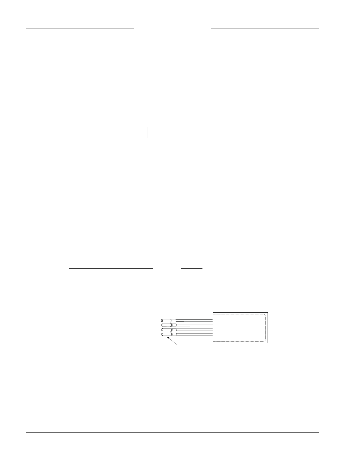
Preliminary
SKY899
Installation Manual
2.19 SOFT-KEYS
If using a WX-1000/SKY497 display connect the soft-keys 1 thru 4 per figures 2-2 or 2-3.
When using an alternate display device reference figure 2-4 as well as manufacturer instructions
concerning these connections. Required soft-key connections will depend upon the alternate display
capabilities.
2.20 SUPPRESSION BUS I/O
The TRC outputs a 100 µs (± 5 µs) suppression pulse on the aircraft suppression bus (P1-93). In addition,
the TRC899 receives suppression signals from all other devices on the suppression bus (e.g., transponder,
DME). (Reference ARINC 735-2 and DO-197.)
CAUTION
The aircraft transponder must have suppression circuitry to ensure that
SKY899 does not paint itself as a target (e.g., TA).
2.21 SYSTEM CONFIGURATION MODULE
The system configuration module (figure 2-8) is used to store aircraft installation dependent information
(e.g., aircraft type, discrete inputs, heading source, speed of data bus, etc.). Aircraft specific information is
selected via the service menu, typically during system setup. Once the setup settings have been saved the
system configuration will stay with the aircraft wiring allowing the TRC to be replaced or exchanged
without having to re-configure the TRC. When powered up the configuration information is sent to the
TRC via the bi-directional serial data bus (SDA).
The system configuration module must be located inside the backshell of
connector P1 and wire-tied to the bundle of wires. Reference figure 2-9.
System Configuration Module connections:
System Configuration Module TRC899
Red (VCC) -to- P1-2 (+3.3V)
Black (Ground) -to- P1-92 (PLUG_GND)
Green (Serial Clock) -to- P1-100 (SCL)
Yellow (Serial Data) -to- P1-99 (SDA)
TO P1-2 (+3.3V)
TO P1-92 (PLUG_GND)
TO P1-100 (SCL)
TO P1-99 (SDA)
Figure 2-8. System Configuration Module
NOTE
TERMINAL
P/N M39029/56-348
RED
BLACK
GREEN
YELLOW
CONFIG MODULE
P/N 814-18005-001
2-28
Rev. A
Page 57
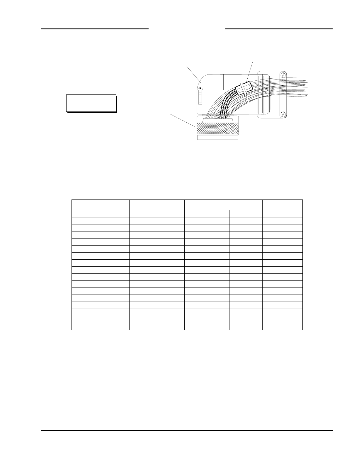
Preliminary
SKY899
Installation Manual
SPLIT ELBOW
90° BACKSHELL
P/N 814-18005-001
(located inside backshell)
P/N 613-10043-001
CONFIGURATION MODULE
.BFGoodrich Avionics Systems, INC.
C
N
I
,
s
m
e
t
s
y
S
s
c
i
n
o
i
v
A
h
c
i
r
d
o
o
e
l
G
u
F
d
o
B
M
n
1
o
0
i
t
0
-
a
r
5
u
0
g
0
i
f
8
n
1
-
o
4
C
Configuration Module
1
8
N
/
P/N 814-18005-001
P
NOT TO SCALE
100 PIN CONNECTOR
P/N 605-10251-001
Figure 2-9. Typical Location of System Configuration Module (Inside Backshell)
2.22 WX-1000/SKY497 DISPLAY (OPTIONAL)
The WX-1000/SKY497 display can be used to display traffic alert/advisory information as well as
Stormscope information. Connections are listed in table 2-2.
Table 2-2. WX-1000/SKY497 Display Connection
Display WIRE COLOR TRC
FUNCTION P101 SUB-CABLE WIRE P1
(Inner Jackets) 2
DPWR+15_OUT 19 WHITE WHITE P1-8
DPWR-15_OUT 14 WHITE ORANGE P1-9
DSPLY_GND 18 WHITE BLUE P1-10
HSYNC_OUT_HI 6 BLUE BLUE P1-11
HSYNC_OUT_LO 5 BLUE WHITE P1-12
VSYNC_OUT_HI 9 ORANGE WHITE P1-13
VSYNC_OUT_LO 10 ORANGE BLUE P1-22
VIDEO_OUT_HI 8 RED WHITE P1-16
VIDEOOUT_LO 7 RED BLUE P1-17
PWR_SW_HI 22 (SW2*) GREEN WHITE P1-4
PWR_SW-LO 23 (SW2*) GREEN BLUE P1- 5
SFTKEY1_IN 13 BLACK WHITE P1-18
SFTKEY2_IN 12 BLACK BLUE P1-19
SFTKEY3_IN 25 YELLOW WHITE P1-20
SFTKEY4_IN 24 YELLOW BLUE P1-21
*SW2 required if WX-1000 Processor installed (see figure 2-2).
2-29
Rev. A
Page 58

Preliminary
SKY899
Installation Manual
2.23 WX-1000 PROCESSOR (OPTIONAL)
The SKYWATCH HP can be interfaced to the Stormscope weather mapping system. The connections are
listed in table 2-3.
Table 2-3. WX -1000 Processor Connection
WIRE COLOR
FUNCTION WX-1000 Processor SUB-CABLE WIRE TRC899
SHIELD P301-5
PWRSWHI P301-21 GREEN WHITE SW2*
PWRSWLO P301-20 GREEN BLUE SW2*
+15 P301-3 WHITE WHITE P1-25
-15 P301-36 WHITE ORANGE P1-26
DSPGND P301-38 WHITE BLUE P1-27
HSYNCHI P301-6 WHITE BLUE P1-28
HSYNCLO P301-23 BLUE WHITE P1-29
VSYNCHI P301-40 ORANGE WHITE P1-30
VSYNCLO P301-7 ORANGE BLUE P1-41
VIDEOHI P301-22 RED BLUE P1-35
VIDEOLO P301-39 RED WHITE P1-36
SFTKEY1 P301-9 BLACK WHITE P1-37
SFTKEY2 P301-26 BLACK BLUE P1-38
SFTKEY3 P301-43 YELLOW WHITE P1-39
SFTKEY4 P301-44 YELLOW BLUE P1-40
*SW2 required if WX-1000 Processor installed (see figure 2-2).
2.24 ANTENNA INSTALLATION
The following paragraphs provide installation details for directional antenna. Standard installation
practices prescribed in FAA Advisory Circular No. 43.13 must be followed. The installer must ensure the
immediate antenna installation area is clean and prepared so that the antenna is electrically bonded
(metal-to-metal contact) to the aircraft. To provide optimum bonding through the mounting holes, prepare
the surfaces with Alodine No. 1001.
To facilitate mounting to the airframe, the dimensions shown in Figure 2-10 can be used to locate and drill
mounting and connector access holes. Connection to the antenna should be made in accordance with the
system interconnect diagram (figure 2-2, 2-3 or 2-4).
NOTE
A doubler plate (not supplied) is required to reinforce the aircraft skin.
1. Connect each of the three antenna cables. Check to ensure that each cable is connected to the correct
antenna connector. Each connector/cable has a matching color band (see note par.2.6.1).
2. Attach the antenna to the aircraft, with the special adapter plate and o-ring, using 10-32 hardware
provided. See Figure 2-11.
1. When mounting the antenna remove the O-ring from the bag and install it
in the O-ring groove on the bottom of the antenna.
2. For pressurized aircraft, use a sealant that meets the requirements of SAE
AMS-S-8802 such as Flamemaster CS3204 class B. For non-pressurized
aircraft, use a non-corrosive sealant that meets the physical requirements
of MIL-A-46146 such as General Electric RTV162.
NOTES
2-30
Rev. A
Page 59
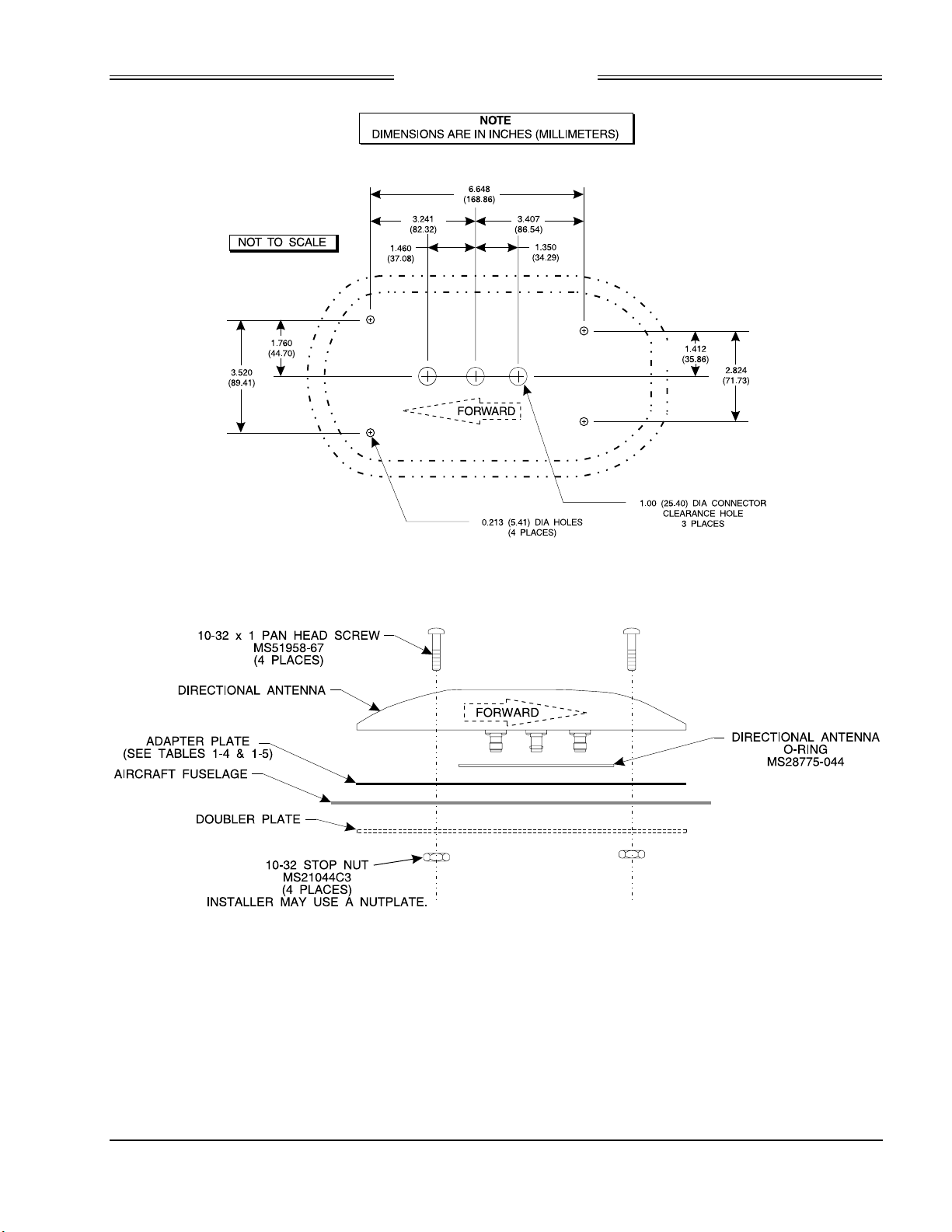
Preliminary
SKY899
Installation Manual
Figure 2-10. Antenna Mounting Holes
Figure 2-11. Directional Antenna Installation
2.25 TRC MOUNTING TRAY INSTALLATION
To accommodate different space limitations, the standard TRC mounting tray (P/N 805-10870-001) can be
channel or flat mounted. To flat mount the tray, simply remove the eight 6-32 (Phillips) screws that secure
the channel to the tray. The ruggedized TRC mounting tray (P/N 805-10870-003), required for rotorcraft
installations, must be channel mounted.
1. Position tray at the installation location.
2-31
Rev. A
Page 60
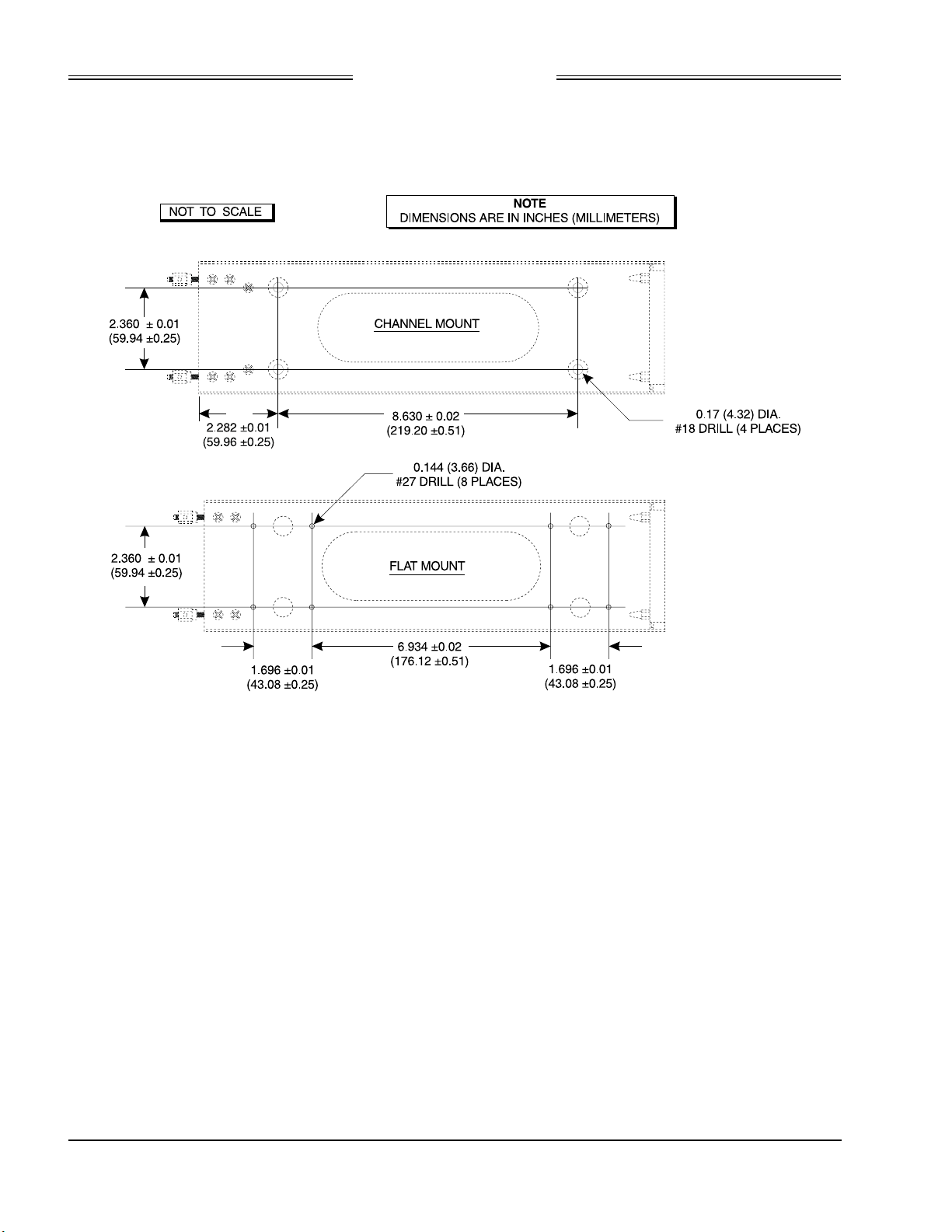
Preliminary
SKY899
Installation Manual
2. Determine centers for mounting holes, and drill for required fasteners. See figure 2-12 (standard tray)
or 2-14 (ruggedized tray).
3. Secure tray in place using suitable 8-32 (channel mount) or 6-32 (flat mount) hardware.
2-32
Rev. A
Figure 2-12. Mounting Holes for Standard Mounting Tray, P/N 805-10870-001
Page 61
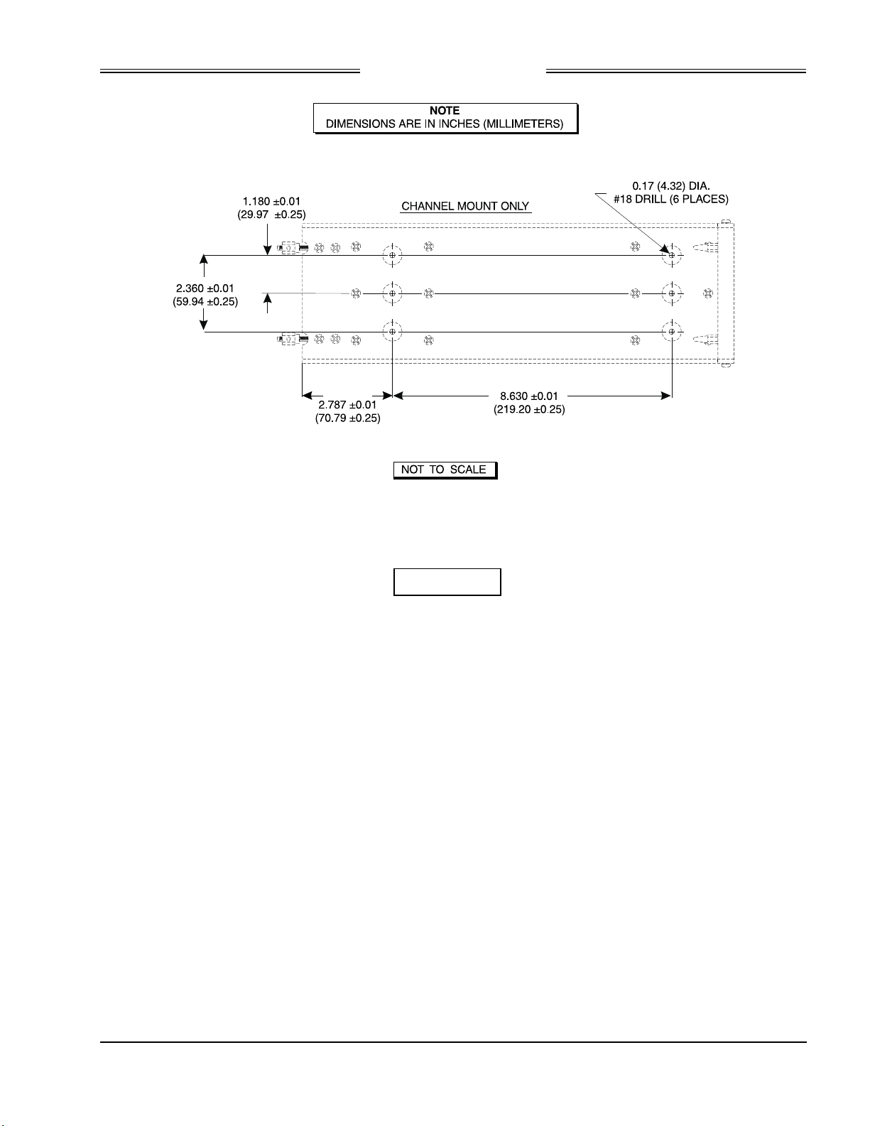
Preliminary
SKY899
Installation Manual
Figure 2-13. Mounting Holes for Ruggedized Mounting Tray, P/N 805-10870-003
2.26 TRC INSTALLATION
CAUTION
Before placing the TRC into its mounting tray, de-energize or disconnect all
power and signal sources and loads used with the SKY899 system.
1. Slide the TRC into the mounting tray (see figure 2-14). Ensure that the rear hold-down pins on the
mounting tray are properly inserted into receptacles on the TRC.
2. Place the retainer cups over the TRC J-hooks. Secure the TRC to the mounting tray by tightening the
self-locking hold-down knobs.
3. Connect the three antenna inputs to the connectors on the front panel.
a. Connect the Sum port antenna connector (P9 - a TNC connector identified with a blue band) to
connector J9 (identified with blue marking).
b. Connect the Probe (Bit) port antenna connector (P10 - a BNC connector identified with a black
band) to connector J10.
c. Connect the Difference (Delta) port antenna connector (P11 - a TNC connector identified with a
red band) to connector J11 (identified with red marking).
4. Connect I/O Signal Cable (P1 - a 100-pin connector) to connector J1.
5. Connect the power cable (P8 - a three-pin connector) to connector J8.
2-33
Rev. A
Page 62
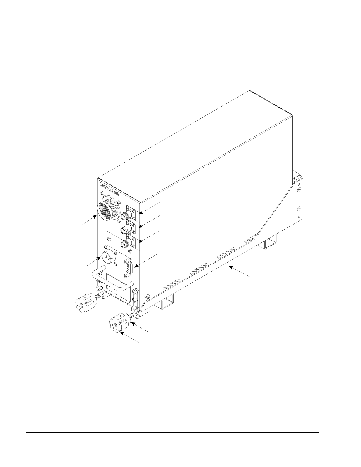
Preliminary
J1
INTERCONNECT
(I/O SIGNAL)
J8
POWER
SKY899
Installation Manual
)
A
e
r
o
s
p
a
c
e
J
I
N
J
1
T
E
R
C
O
N
N
E
C
T
J
8
P
O
W
E
R
J
1
2
M
E
M
O
R
Y
C
9
J
1
0
J
1
1
J
7
T
E
S
T
A
R
D
S
-
9
J
-
0
1
J
-
1
1
J
A
F
-
7
J
E
U
L
B
(
M
U
E
B
O
R
P
R
E
F
F
I
D
Y
R
O
T
C
)
K
C
A
L
B
(
N
E
E
T
)
D
E
R
(
E
C
T
S
MOUNTING TRAY
2-34
Rev. A
RETAINER CUPS
(2 PLACES)
HOLD-DOWN KNOBS
(2 PLACES)
Figure 2-14. TRC899 Installation
Page 63
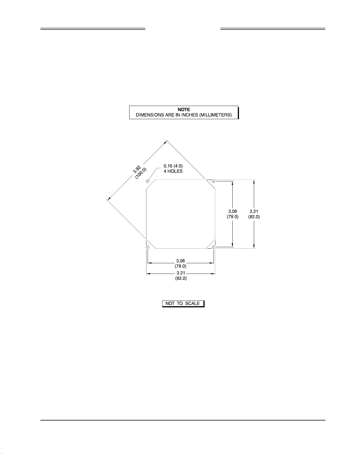
Preliminary
SKY899
Installation Manual
2.27 MOUNTING THE WX-1000/SKY497 DISPLAY
The display mounts in a standard 3ATI panel cutout (figure 2-15). The unit may be mounted from the
front or rear. The following paragraphs describe the installation procedure.
2.27.1 Panel Cutout
Refer to figure 2-15 for the panel cutout and mounting hole dimensions. Drill and punch the required
holes. The instrument panel cutout is a standard 3ATI.
Figure 2-15. Instrument Panel Cutout and Mounting Holes
2-35
Rev. A
Page 64
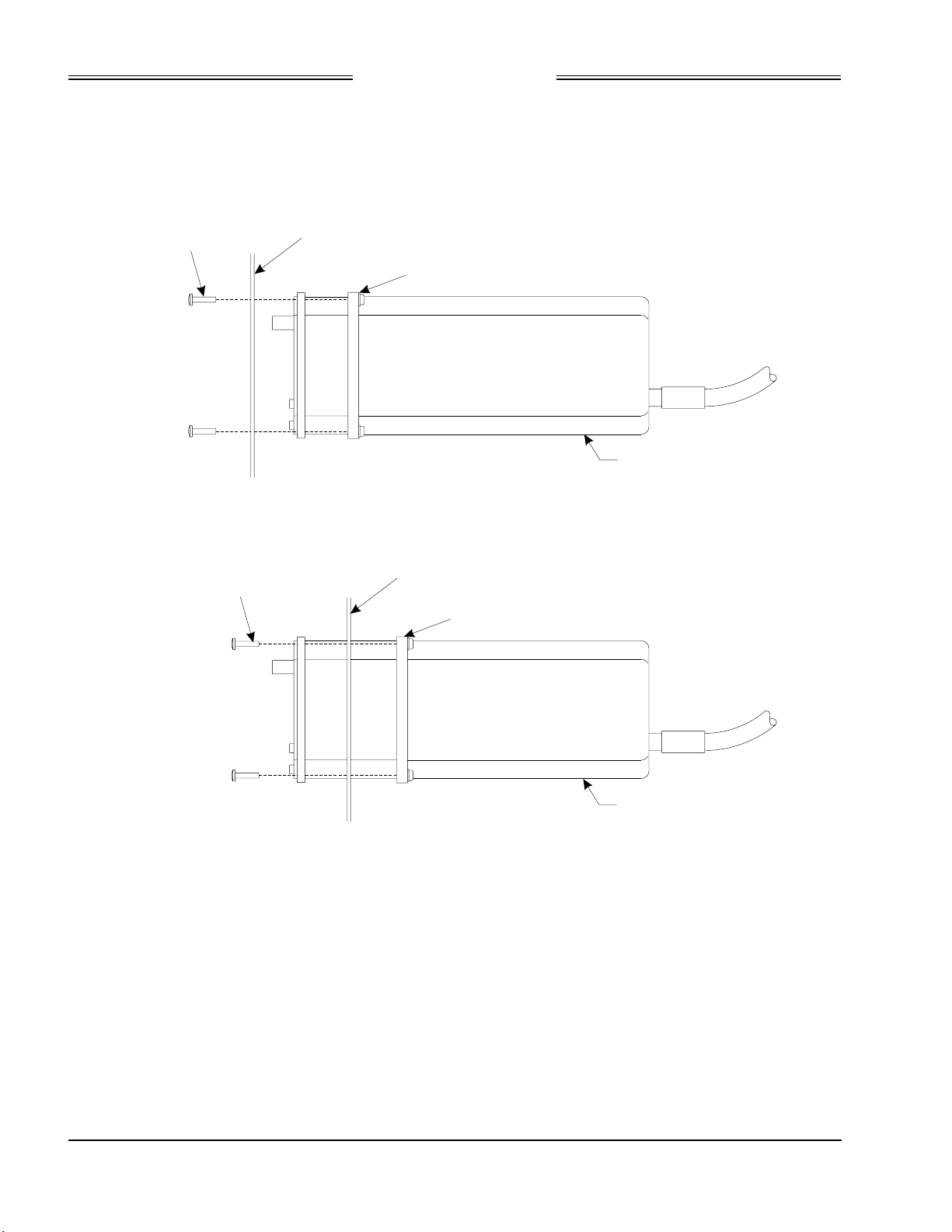
Preliminary
SKY899
Installation Manual
2.27.2 Display Installation
Figure 2-16 shows a typical display installation. The display can be mounted to the instrument panel from
the front or from the rear. An optional mooring clamp is available for increased stability in high-vibration
environments.
6-32 X 3/4 PHM
(QTY 4)
AIRCRAFT PANEL
MOORING PLATE (NOT SUPPLIED)
DISPLAY
REAR MOUNT
6-32 X 3/4 PHMS
(QTY 4)
FRONT MOUNT
Figure 2-16. Display Installation
Use rivnuts® or a mooring clamp to secure the display to the instrument panel.
1. The mooring clamp is not furnished with the display.
2. A mooring clamp (P/N 78-8060-5856-2) can be ordered when the order for the
display is placed.
3. A 3ATI mooring clamp is also available from:
MSP, Incorporated
R.R. 4, Box 383A
Nashville, Indiana 47448
Tel. (812) 988-6623 or FAX (812) 988-6181
AIRCRAFT PANEL
MOORING PLATE (NOT SUPPLIED)
DISPLAY
NOTE
2-36
Rev. A
Page 65
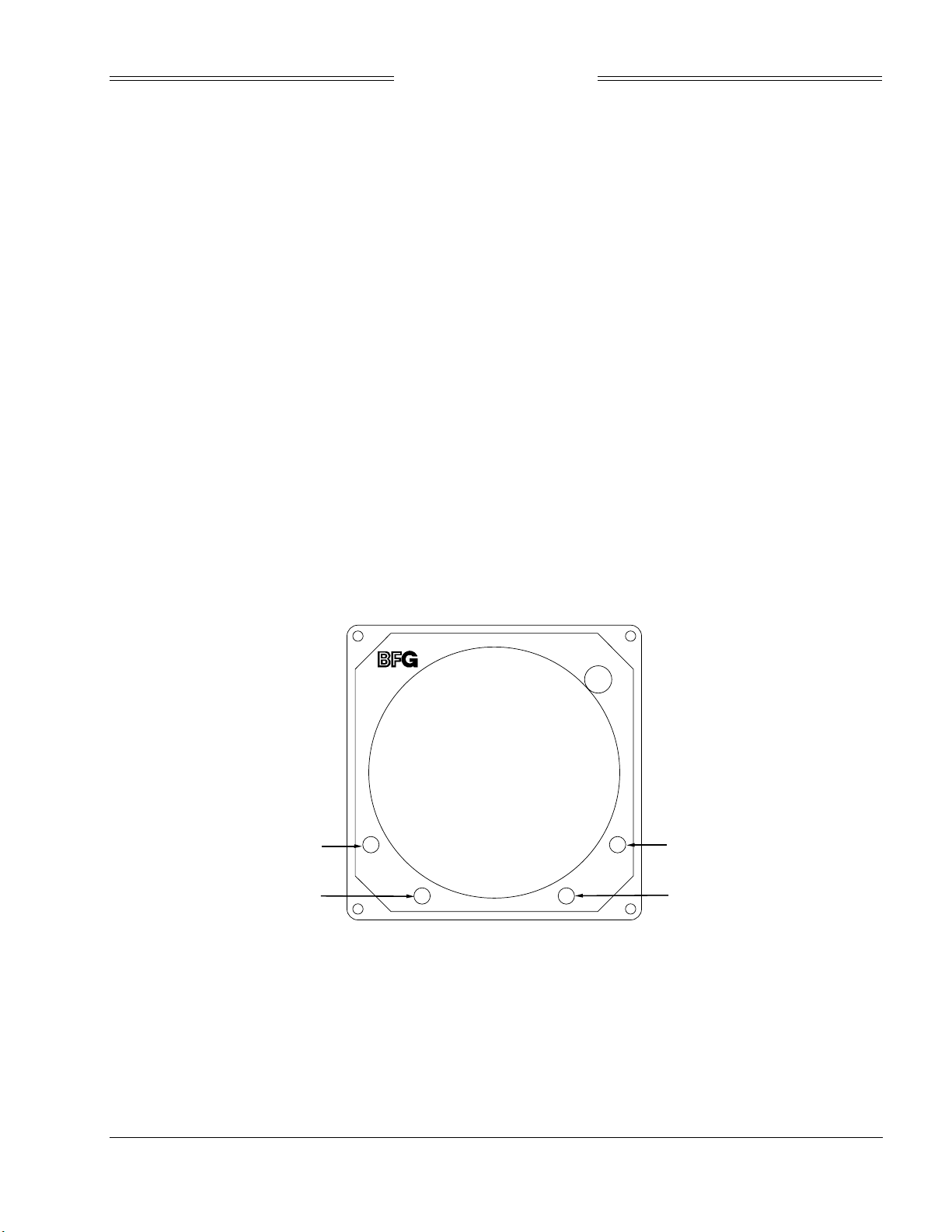
Preliminary
SKY899
Installation Manual
CHAPTER 3
INSTALLATION CHECKOUT
3.1 INTRODUCTION
This section contains instructions for using the BFGoodrich Avionics Systems TT391 Flightline Tester to
do post-installation checkout of the SKY899. Detailed setup, operation and maintenance information for
the TT391 Flightline Tester is provided in the TT391 Instruction Manual.
NOTES
1. This procedure assumes familiarity with the set up and operation of the TT391
Flightline Tester.
2. All test equipment used in completing these tests shall be calibrated in
accordance with the manufacturer's recommendations.
3. This section provides checkout information for the SKY899 using the WX-1000
Display. If using an alternate display use Appendix F for installation checkout.
4. Checkout of the WX-1000 processor should be done in accordance with the
procedures detailed in the WX-1000 Installation Manual.
This procedure will validate the installation and return to service of the SKY899.
3.2 CONTROLS
All operating controls are located on the front of the display. Figure 3-1 shows the locations of the controls.
Complete operating instructions are provided in the SKY899 Pilot's Guide supplied with each system.
BRT
OFF
4
3
OFF/BRT
Switch
1
2
Figure 3-1. Controls
Power is applied by rotating the knob clockwise past the detent. Continued
clockwise rotation increases display brightness.
1, 2, 3, & 4
Pushbuttons
Also referred to as soft-keys (1), (2), (3), and (4). In every operating mode a label
identifying the button function will be displayed next to the button.
3-1
Rev. A
Page 66

Preliminary
SKY899
Installation Manual
3.3. CHECKOUT PROCEDURE
The TT391 Flightline Tester simulates both a ground based secondary surveillance radar (SSR) and an
airborne transponder. With the SKY899 set to GROUND TEST (i.e., the barometric altimeter is simulated
to 50,000 ft, heading simulated to 0 degrees, and the radar altimeter simulated to 2,500 ft) the TT391 will
simulate two targets; a Traffic Advisory (i.e., a solid circle) at ¼ nm and Other Traffic (i.e., open diamond)
at 4.5 nm. Both targets will be displayed in level flight at own aircraft altitude (i.e., "00" displayed above
the traffic symbol).
If the indications given in the following procedure, except for the Flightline Tester, are not obtained, refer
to the troubleshooting procedures in Chapter 4. If indications given for the Flightline Tester are not
obtained, refer to the maintenance section of the TT391 Instruction Manual.
1. Make sure the aircraft's transponder is in the STBY mode and the DME is turned OFF. At the
aircraft's instruments, verify all compass/HSI flags are valid. Verify all avionics equipment that is
interfaced with the SKY899 (i.e., GPS, ADC, AHRS, encoding altimeter) are turned ON.
NOTE
After power up, it may take a couple of minutes for the altitude encoder to
return a valid altitude to the transponder and SKY899.
2. Turn SKY899 ON. The display will show a start-up screen similar to one shown in figure 3-2. After
start-up screen appears, rotate the OFF/BRT switch. Verify that clockwise rotation increases display
brightness.
BRT
OFF
BFGoodrich Avionics Systems, Inc.
Figure 3-2. Start-up Screen
After approximately thirty seconds the display will show the STANDBY screen (see figure 3-3).
If the TRC has not been calibrated to the directional antenna the display
may show a “SKY899 FAILED” message. Calibration will be done during
system setup.
NOTE
3-2
Rev. A
Page 67
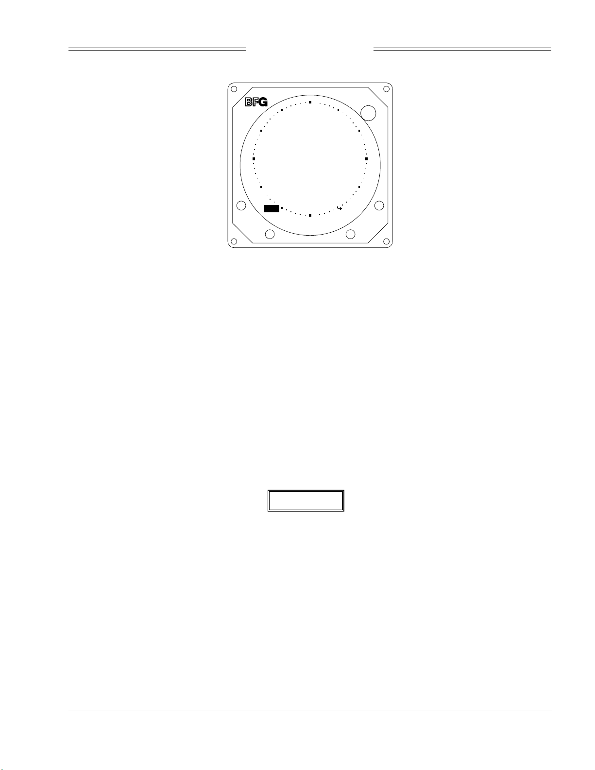
Preliminary
SKY899
Installation Manual
BRT
OFF
SKY899
Standby
OPRMSG
TEST
Figure 3-3. Standby Screen
3.3.1 System Setup
The system configuration can be done using the service menu or it can be downloaded with a previously
saved configuration using the Compact Flash Card. Both setup procedures are described below and assume
familiarity with service menu operation, see chapter 4 for operation information.
System Configuration (via Service Menu)
1. Turn SKY899 OFF and then enter the Service Menu (see paragraph 4.4) by holding the left two
buttons (soft-keys 1 and 2) depressed as the system is turned ON.
2. From the Service Menu, select Setup and then select Aircraft Type. The Aircraft Type menu will
appear, select correct aircraft type (fixed wing or rotorcraft). Select exit to return to setup menu.
3. From the Setup menu, select Antenna System:
a. The Antenna System menu will appear, select correct antenna location (top or bottom).
b. The antenna model menu will appear, select correct antenna model (NY164 or NY156).
c. Verify Antenna location and model, then Select exit until you return to setup menu.
WARNING
Verify displayed antenna position matches antenna location on the aircraft
(top or bottom). Failure to do so could give incorrect traffic bearing.
4. From the Setup menu, select Audio Level:
a. The Audio Level menu will appear, set the desired audio level using the up and down
selections (level is adjusted in 5% increments).
b. Test the audio level by selecting Test. Verify the aural Traffic Traffic message is heard at a
comfortable level, then Select exit to return to setup menu.
5. From the Setup menu, select Communication Ports:
a. The Arinc 429 Receivers menu will appear, with all source avionics equipment turned on
select autodetect. The Please wait... message will appear for approximately 20 seconds as the
system configures the receiver channel, equipment type, and speed.
3-3
Rev. A
Page 68

Preliminary
SKY899
Installation Manual
b. Verify receiver channels match desired wiring interface. If an interconnect error is discovered,
correct wiring and then re-select autodetect. (To manually change individual receiver
channels, highlight and select that channel. See see paragraph 4.4.1.4)
NOTES
1. It is possible for multiple data inputs (barometric altimeter, radio
altimeter, magnetic heading and GPS navigation) from one source to be
received on one channel (e.g., ARINC-429 superbus). Multiple data
inputs will be indicated by the word Multi in the Arinc 429 Receiver
Menu. (See see paragraph 4.4.1.4)
2. The data rate for RX channels 1 and 2 must be set to the same speed (12.5
or 100 kHz). The data rate for RX channels 3 and 4 must be set to the
same speed (12.5 or 100 kHz). The data rate for channel 5 is independent
of the other receivers. Channel 5 can be set to 12.5 or 100 kHz.
c. Select exit until you return to Setup Menu.
6. From the Setup menu, select Avionics Equipment:
a. The Equipment menu will appear, select Browse All Avionics.
The system will step you through each equipment sub-menu. As you select the equipment the
next equipment menu in the loop will appear. Once you have stepped through all 8 submenus, the equipment menu will reappear.
b. Verify the equipment shown in parentheses under each equipment title matches the wiring
interface. To change equipment source, highlight and select it from the menu. (See see
paragraph 4.4.1.5.)
c. Select exit until you return to Service Menu.
d. The Save or Revert menu will appear upon exiting setup menu. Select Save Changes to keep
current configuration. (Selecting Revert to Old Settings will cause system to exit the service
menu without saving changes.)
7. From the Service Menu, select Calibration:
a. Select correct antenna location (top or bottom). The "SKY899 Antenna Calibration in
Process..." message will appear. The Built In Test (BIT) signal phase will be calibrated for the
TRC, cable connections, and antenna (see paragraph 4.4.3).
b. Verify calibration passed: A new bit phase value is displayed and no error messages appeared.
c. Press exit to return to Service Menu screen.
8. Perform system setup verification and operation procedure in paragraph 3.3.2.
Download System Configuration (via Compact Flash Card)
1. With the SKY899 OFF, lift the memory card door on the front of the TRC899 and insert the compact
flash card into J12 connector.
2. Enter the Service Menu (see paragraph 4.4), select Configuration Management.
3. At the Configuration Management menu select Retrieve from CF. Verify the "download was
successful" message is displayed. If an error occurs during download, the configuration setup must be
done manually (see above "System Configuration" procedure).
4. Turn off the SKY899 and remove the compact flash card from J12 memory card connector.
5. Perform the system setup verification and operation procedure below (see paragraph 3.3.2) to verify
configuration data was downloaded correctly.
3-4
Rev. A
Page 69

Preliminary
SKY899
Installation Manual
3.3.2 System Setup Verification and Operation
1. Turn ON all avionics equipment interfaced to the SKY899.
2. From the Service Menu (see paragraph 4.4), select Information.
3. From the Information menu, select Data Monitor. The Data Monitors menu will appear.
4. Select each of the data monitors and verify the sensor information is correct (see paragraph 4.4.2.3):
a. Change the status of the landing gear, squat switch, altitude, and heading sensors.
Verify data monitors show the correct input changes (i.e., sensing of these signals).
b. If the information is not correct, the sensor has failed to communicate with the TRC. Check
operation of the sensor and connections between the TRC and sensor.
c. Select exit until you return to the Service Menu.
5. From the Service Menu, select Ground Test (see paragraph 4.4.4).
6. From the Ground Test menu, select Perform Ground Test.
7. Verify operation of range function. Soft-key (3) is labeled to indicate the current range. Press soft-key
(3) to toggle the display range between 2, 6 and 15 nm.
8. Select the 6 nautical mile range.
9. Verify that the system toggles through the altitude display modes. Soft-key (2) is labeled to indicate
the current mode. Press Soft-key (2) to select normal (NRM), below (BLW), above (ABV), and
unrestricted (UNR).
10. Select the NRM (normal) mode.
11. Position the aircraft with the nose aligned on any 90 degree heading. Avoid areas within 250 ft of
obstructions (e.g., hangers, large aircraft, control towers, etc.) where there is a potential for multipath
problems. Locate and mark test points at 30 degree intervals (i.e., 000, 030, 060, 090, 120, 150, 180,
210, 240, 270, 300, and 330 degrees) with respect to the directional antenna. Mark these points at the
same distance, between 100 and 150 ft, from the aircraft.
12. Position the TT391 Flightline Tester on one of the test points identified in previous step.
CAUTION
The Flightline Tester is not weatherproof when the lid is open. Do not setup
or operate the Flightline Tester in conditions of rain, sleet, etc.
13. Setup and verify operation of the TT391 Flightline Tester:
a. Open the chassis lid and remove the lid from the chassis by sliding the lid off of the hinge pins
(sliding it to the right). The lid "stay" must be removed from the lid before mounting. The stay
will pop off of the lid. (The stay is the hinged part that props the lid open on the chassis).
The Patch Antenna may be used without a tripod. The Patch Antenna can be
held, or secured, and pointed towards the SKYWATCH HP aircraft under test
WITH THE MOUNTING STUD POINT TOWARD THE GROUND. This orientation is
critical.
b. Mount the chassis lid, with the Patch Antenna facing the aircraft, onto a tripod (not included).
The tripod must be capable of holding the antenna (approximately 2.5 lb) and must provide a
standard base mounting stud threaded 1/4"-20. A typical tripod mount is shown in figure 3-4.
NOTE
3-5
Rev. A
Page 70
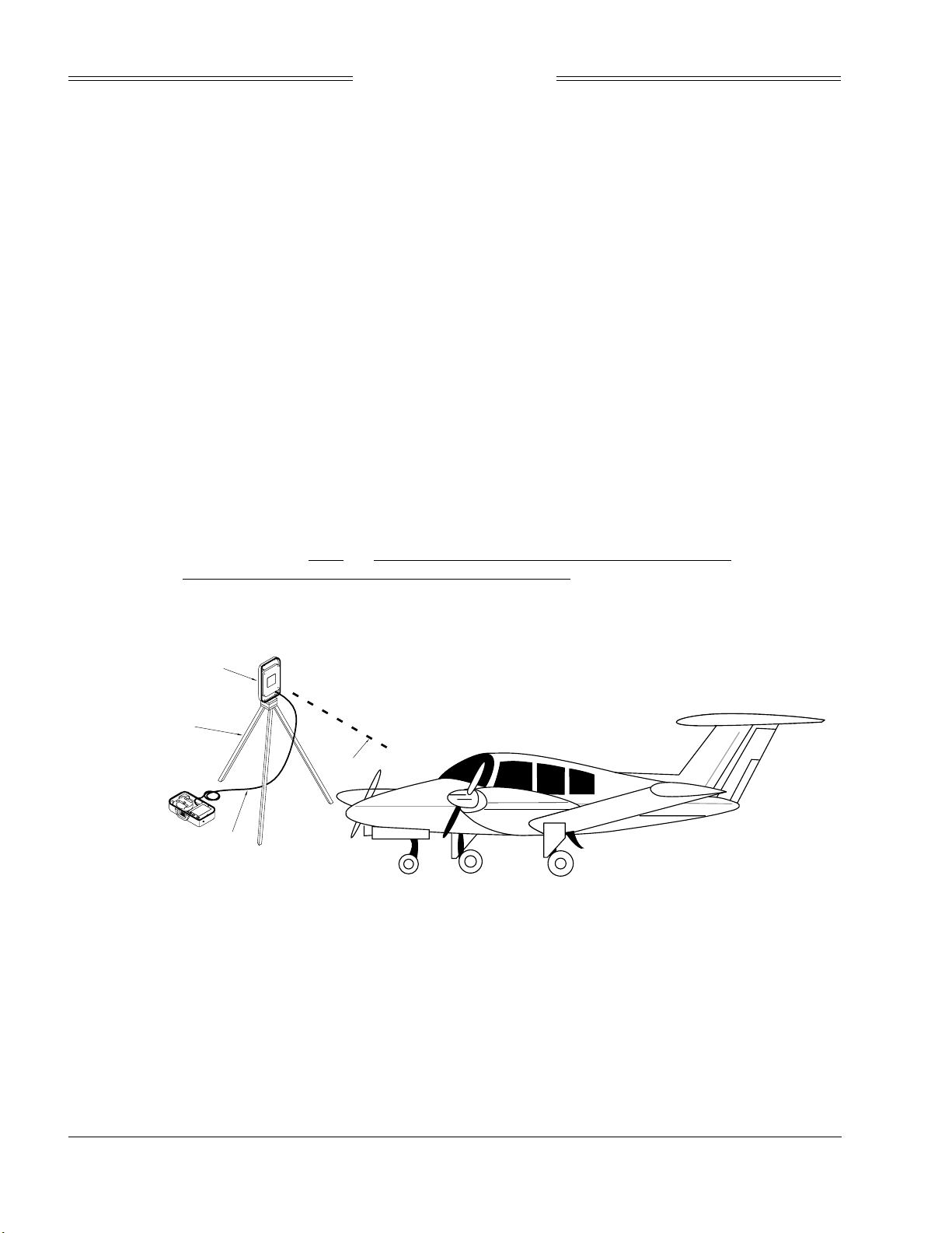
Preliminary
SKY899
Installation Manual
c. If the internal batteries are being utilized, proceed to sub-step f. If the Flightline Tester AC
Converter Power Supply is to be utilized, proceed to sub-step d.
d. Connect the AC Converter Power Supply cable connector to the chassis external connector.
e. Connect the AC Converter Power Supply input power cable connector to one of the following AC
sources:.
• 115 Vac, 60 Hz
• 115 Vac, 400 Hz
f. Set the Flightline Tester POWER switches to the ON position.
g. Verify that the LOW indicator is not steady on (it may flash). If the LOW indicator remains on
(i.e., lit), perform one of the following three options.
• Use the AC Converter Power Supply to power the unit.
• Recharge the internal batteries.
• Replace the internal batteries.
h. Set the SELF-TEST switch to the 1030 position and verify that the 1030 indicator blinks on for
1/2 second every 5 seconds.
i. Set the SELF-TEST switch to the 1090 position and verify that the 1090 indicator blinks on for
1/2 second every 5 seconds.
j. Set SELF-TEST switch to center position (off). Set the POWER switch to the OFF position.
NOTE
Care should be taken to ensure that the Patch Antenna is connected to TT391
connector J1 and NOT J2. IF THE PATCH ANTENNA IS CONNECTED TO
J2 THE TT391 WILL NOT FUNCTION CORRECTLY.
k. Connect the Flightline Tester coax cable to J3 on the Patch Antenna and to connector J1 in the
chassis. (J2 should remain capped by the dust cover).
PAT C H
ANTENNA
ASSEMBLY
TRIPOD ASSEMBLY
(OPTIONAL -
NOT INCLUDED)
COAX
CABLE
Figure 3-4. Typical Patch Antenna Tripod Mount
RF
LINK
3-6
Rev. A
Page 71

Preliminary
SKY899
Installation Manual
14. From each test point (see step 12):
a. Position the TT391 Patch Antenna facing the SKYWATCH HP aircraft under test.
b. Set the TT391 POWER switch to the ON position.
c. Verify that the display shows, in the direction (± 30 degrees) of the TT391, two targets; a Traffic
Advisory (i.e., a solid circle) at ¼ nm and Other Traffic (i.e., open diamond) at 4.5 nm. Both
targets will be displayed in level flight at own aircraft altitude (i.e., "00" displayed above the
traffic symbol).
NOTES
1. If the display reflects a gross error in target bearing, check the directional
antenna cables at TRC connectors J9 (sum port) and J11 (difference port).
They may be reversed. A further indication of this condition would be a
target that moved in a counter-clockwise direction when the TT391 is
moved in a clockwise direction.
2. Multiple targets or a faulty bearing may result from multipath distortion
(see step 1).
3. During these tests, the SKY899 may detect and display other active
targets.
4. To obtain a better line of sight, it may be necessary to elevate the patch
antenna.
d. Set the TT391 POWER switch to the OFF. Repeat procedure from each test point. Step 15 can
be done from the last test point.
NOTE
To prevent SKYWATCH HP from tracking the movement of the test-set, it is
necessary to set the TT391 POWER switch to OFF after completing each
bearing measurement.
15. Return the TT391 assemblies to their position in the aluminum carrying case.
16. Restart SKY899 by cycling power OFF and then ON.
17. Connect an oscilloscope to the suppression bus and verify that the SKY899 suppression pulse (100 µs
±5 µs) exceeds +15 V dc. If less than +15 V dc the suppression bus is overloaded. Check all equipment
connected to the bus. Repair/replace the offending device.
18. This completes the post installation checkout procedure.
3.4 SELF TEST
1. Turn SKY899 OFF and then:
a. Make sure the aircraft's transponder is in the STANDBY, ON, or ALT mode.
After power up, it may take a couple of minutes for the altitude encoder to
return a valid altitude to the transponder and SKY899.
NOTE
b. If installed, power up the radio altimeter.
c. Make sure all compass/HSI flags are cleared from the aircraft's instruments.
2. Turn SKY899 ON. The display should show a start-up screen similar to one shown in figure 3-2.
3-7
Rev. A
Page 72
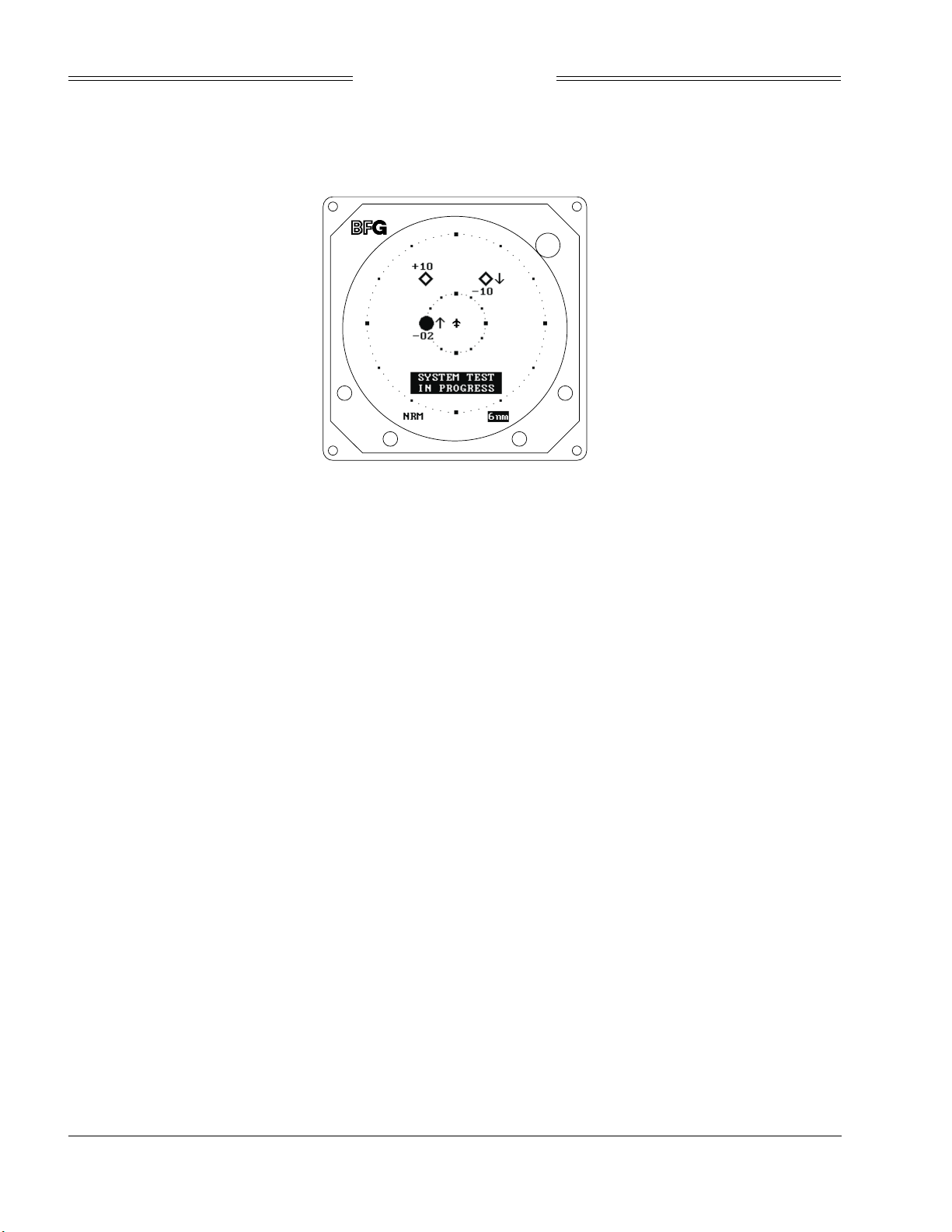
Preliminary
SKY899
Installation Manual
3. After approximately thirty seconds, observe the STANDBY screen and then press the TEST button
(soft-key (2)).
4. The display should present a screen similar to that shown in figure 3-5.
BRT
OFF
Figure 3-5. Self Test Screen
5. If the SKY899 passes the self-test, the system will return to the STANDBY screen (see figure 3-3) and
the voice message, "SKYWATCH SYSTEM TEST PASSED," will be enunciated over the cockpit audio
system.
6. If you do not hear the voice message or if the voice message is of insufficient volume:
a. Check headphones/speaker and aircraft audio panel switch settings.
NOTE
Audio levels can be adjusted via the service menu and at the aircraft audio
panel. There is no internal audio adjustment.
b. Reset the audio level via the service menu (see paragraph 4.4.1.3).
c. Check audio connection to the TRC:
1) 600-ohm audio systems should be connected to P1-89 (AUDIO_H).
2) 150-ohm audio systems should be connected to P1-90 (AUDIO_L).
3) Audio common is connected to P1-91 (AUDIO_C).
NOTE
Audio output from the TRC is transformer isolated.
7. If SKY899 fails the self-test:
a. The "SKY899 Failed" screen with an error message indicating the type of failure will be
displayed.
b. The voice message, "SKYWATCH SYSTEM TEST FAILED", will be enunciated over the cockpit
audio system.
c. To re-test, press TEST button soft-key (2).
d. Refer to the fault isolation procedures in Chapter 4.
3-8
Rev. A
Page 73

Preliminary
SKY899
Installation Manual
CHAPTER 4
MAINTENANCE
4.1 INTRODUCTION
This chapter contains general flight-line maintenance and troubleshooting procedures for installations
interfaced to WX-1000/SKY497 display or an alternate display. Removal of components is on condition of
failure. Troubleshooting is intended to aid in isolating failures to a defective assembly. Each time the TRC,
directional antenna, or directional antenna cables (including connectors) are replaced, the TRC must be
calibrated to the directional antenna (refer to paragraph 4.4.3).
4.2 CONTINUED AIRWORTHINESS
No scheduled maintenance is required to ensure continued airworthiness.
4.3 PERIODIC MAINTENANCE
At regular inspection intervals, do the periodic maintenance procedures of paragraph 4.3.1 thru 4.3.3.
4.3.1 WX-1000/SKY497 Display
1. Check that indicator cable is properly mated and secured.
2. Check to ensure unit is properly placed and secured to the instrument panel.
CAUTION
Do not use cleaning solvents on the viewing face.
3. Check face-plate for cleanliness. Wipe the viewing face with a damp lint-free, static-free cloth. If
necessary, clean with a soft cloth moistened with a mild solution of soap and water. Take care to
prevent cleaning solution from running down inside the case.
4.3.2 TRC
1. Check that connectors are properly mated and secure.
2. Check to ensure that the hold-down knobs on the mounting tray are secured to the TRC.
4.3.3 Antenna
1. Check for dents, cracks, and punctures.
Do not paint the antennas.
Do not use cleaning solvents on the antennas.
2. Remove all dirt and grease from surface areas. Clean with a soft cloth moistened with mild soap and
water.
CAUTION
3. Visually inspect sealant around the antenna base. Reapply sealant if required.
4-1
Rev. A
Page 74
Preliminary
SKY899
Installation Manual
4.4 SERVICE MENU
The Service Menu is intended as an aid in installing, testing and troubleshooting the SKY899 (figure 4-2).
The Service Menu is not intended to be used by the pilot during normal system operation. A service menu
tree is provided at the end of this paragraph (figure 4-3). When interfaced to an alternate display the
service menu functions are accessed via a computer (figure 4-1) using a terminal emulation program, see
appendix E for operating instructions. To access the service menu from the terminal emulation program,
type the menu command and then type the corresponding prefix for each selection (e.g., 1, 2, x, etc.).
Service Menu
1 Setup
2 Information
3 Calibration
4 Ground Test
5 Configuration Management
x Exit
Figure 4-1. Service Menu (Terminal Emulation Program)
Access the Service Menu on a WX-1000/SKY497 display by holding soft-keys (1) and (2) (the left two
buttons) depressed as the system is turned on. Hold the buttons until the Service Menu is displayed. The
Service Menu is shown in figure 4-2.
BRT
OFF
SERVICE MENU
Setup
Information
Calibration
Ground Test
Configuration Management
EXIT
NEXT
Figure 4-2. Service Menu (WX-1000/SKY497 Display)
Ground Test is available only if squat switch input indicates aircraft is on the ground.
SEL
PREV
The buttons perform the following operations:
EXIT - backs up one screen (if in service menu screen it will exit and enter normal/standby mode).
NEXT - scrolls to the next item.
SEL - selects the highlighted item.
PREV - scrolls to the previous item.
The individual menu items are explained in the following paragraphs.
4-2
Rev. A
Page 75
Preliminary
SKY899
Installation Manual
NOTE
Service Menu screens are shown for documentation purposes only. Each system
may be configured differently and live data will correspond to the sensors
installed in a particular aircraft.
4.4.1 Setup
The setup menu configures the SKY899 system to your specific installation. Setup covers the aircraft type,
antenna system, audio level, communication ports, and avionics equipment. Setup can be accessed by
selecting it in the service menu screen.
The Setup menu provides the following choices:
BRT
Setup
Aircraft Type
Antenna Sytem
Audio Level
Communications Ports
Avionics Equipment
OFF
PREV
PREV
SEL
SEL
OFF
BRT
Screen appears
when exiting Setup
menu and changes
have been made
EXIT
NEXT
The following menu will appear when you exit the setup menu if changes were made in the system
configuration. Save changes will store configuration settings in system configuration module. Revert to old
settings will restore the system configuration back to the last saved configuration.
Save or Revert
Changes have been made!
Save Changes
Revert to Old Settings
NEXT
Each setup item is covered in the following paragraphs.
4.4.1.1 Aircraft Type
The aircraft type menu allows you to choose between fixed wing or rotorcraft aircraft.
4-3
Rev. A
Page 76
Preliminary
SKY899
Installation Manual
The Aircraft Type menu provides the following choices:
Aircraft Type
*None*
Fixed Wing
Rotorcraft
OFF
BRT
EXIT
NEXT
SEL
PREV
4.4.1.2 Antenna System
The SKY899 allows you to install the antenna on top or bottom of aircraft and can use the NY156 (TCAS I
installation) or NY164 antenna. Only one antenna location can be selected, when choosing an antenna
location the other location will automatically be set to "None."
The Antenna System menu provides the following choices:
BRT
Antenna System
Top Antenna
*NY156 Directional*
Bottom Antenna
[None]
EXIT
NEXT
OFF
SEL
PREV
Selecting Top Antenna (or Bottom Antenna) provides the following choices:
4-4
Rev. A
BRT
OFF
Top Antenna
None
NY164 Directional
*NY156 Directional*
EXIT
NEXT
SEL
PREV
(Bottom Antenna menu is same as Top Antenna menu)
Page 77
Preliminary
SKY899
Installation Manual
4.4.1.3 Audio Level
The audio level menu allows you to set and test the audio level output. Audio level range is 0 to 40 mW
into 600 Ohm load, indicated by percentage (0-100%). Audio level can be adjusted up or down in 5%
increments. Selecting test will cause the "traffic traffic" aural message to be annunciated over the aircraft
audio system.
The Audio Level menu provides the following choices:
BRT
Audio Level
Volume
[50%]
Up
Down
Test
OFF
EXIT
NEXT
SEL
PREV
4.4.1.4 Communication Ports
Configuring the communication ports should be done before configuring the avionics equipment. Select
Communication Ports from the Setup menu, the ARINC 429 receiver menu will be displayed. With all
avionics equipment turned on, you can set the speed and the equipment type for each channel
automatically (Autodetect) or individually. Autodetect is recommended to configure the ARINC 429
receiver's, however you can manually select the equipment type and speed for each individual channel.
Selecting Communication Ports from the Setup menu will cause the ARINC 429 Receivers menu to appear:
BRT
PREV
OFF
Please wait... will
be displayed while
autodetect is being
performed
SEL
Receiver menu shows
the 5 RX channels, the
429 source and the
speed. To change
individual channel,
highlight desired channel
and press SEL.
Arinc 429 Receivers
Autodetect
Ch. 1: Multi 100 kHz
Ch. 2: None 100 kHz
Ch. 3: None Auto
Ch. 4: None Auto
Ch. 5: None Auto
EXIT
NEXT
NOTES
1. The data rate for RX channels 1 and 2 must be set to the same speed
(12.5 or 100 kHz).
2. The data rate for RX channels 3 and 4 must be set to the same speed
(12.5 or 100 kHz).
3. The data rate for channel 5 is independent of the other receivers.
Channel 5 can be set to 12.5 or 100 kHz.
4-5
Rev. A
Page 78
Preliminary
SKY899
Installation Manual
Selecting any channel (ch.1 thru ch.5) will cause that individual Rx channel menu to appear:
BRT
Arinc 429 Rx Ch 1
Type:
Speed: 100 kHz
ADC
GPS
OFF
EXIT
NEXT
SEL
PREV
Selecting Type will cause the Equipment Type menu to appear:
Equipment Type
None
*ADC*
AHRS
*GPS*
Rad Alt
EXIT
NEXT
OFF
SEL
PREV
Selecting Speed will cause the Speed menu to appear:
Speed
12.5 kHz
100 kHz
OFF
BRT
More than one source can be
selected for each 429 RX
channel. Each selected source
will have an asterisk's before
and after it. If more than one
source is selected the word
"Multi" will appear in the ARINC
429 Receivers menu.
BRT
4-6
Rev. A
NEXT
SEL
PREV
Page 79
Preliminary
SKY899
Installation Manual
4.4.1.5 Avionics Equipment
Avionics equipment menu allows you to set the source equipment interfaced to SKY899 and sets discrete
inputs. With all of the avionics turned on in the aircraft select Browse All Avionics from the avionics
equipment menu. This will sequentially step you through the setup of all avionics equipment interfaces.
After completing Browse All Avionics selections, corrections can be made by selecting the individual items
from the Equipment menu.
The Avionics Equipment menu provides the following choices:
BRT
Equipment
Browse All Avionics
GPS Nav
[Gama]
Magnetic Heading
[None]
Barometric Altitude
[None]
EXIT
NEXT
OFF
SEL
PREV
If ARINC-429 equipment is selected in the avionics equipment menu, but was not configured in the
communications port menu the following menu will appear:
Using Next button to scroll
down will cause these
additional menu choices to
appear one at a time.
Radio Altitude
[None]
Landing Gear
[None]
Weight-On-Wheels
[None]
Audio Suppression
[None]
External Display
[None]
No Chan Assigned
Choose a channel
Ch.1: None 100 kHz
Ch.2: Multi 100 kHz
Ch.3: None 100 kHz
Ch.4: None 100 kHz
Ch.5: None 100 kHz
EXIT
NEXT
The Avionics Equipment sub-menus are as follows.
The GPS Nav menu provides the following choices:
*None*
GAMA
ARINC 743A
EXIT
NEXT
GPS Nav
PREV
PREV
SEL
SEL
OFF
OFF
BRT
This Menu appears when
ARINC 429 equipment has
been selected, but was not
assigned to a channel via
the Communication Ports Menu
BRT
4-7
Rev. A
Page 80
Preliminary
SKY899
Installation Manual
The Magnetic Heading menu provides the following choices:
Magnetic Heading
*None*
Synchro Compass
AHRS
OFF
BRT
EXIT
NEXT
SEL
PREV
Selecting Synchro Compass causes Heading Valid Line menu to appear:
BRT
OFF
Heading Valid Line
*None*
Valid Low
Valid High
EXIT
NEXT
SEL
PREV
The Barometric Altitude menu provides the following choices:
BRT
Barometric Altitude
*None*
ADC
Encoding Altimeter
OFF
EXIT
NEXT
Selecting ADC will cause the ADC menu to appear:
*None*
ARINC 429
EXIT
NEXT
4-8
Rev. A
ADC
PREV
PREV
SEL
SEL
OFF
BRT
Page 81
Preliminary
SKY899
Installation Manual
The Radio Altimeter menu provides the following choices:
Radio Altimeter
*None*
Arinc429
Arinc 552
Arinc 552A
Bonzer Mark 10X
Collins ALT-50
Collins ALT-55
EXIT
NEXT
PREV
SEL
OFF
BRT
Using Next button to scroll
down will cause these
additional menu choices to
appear one at a time.
King KRA10/10A
King KRA 405
Sperry AA-100
Terra TRA 3000
Selecting a DC analog radio altimeter will cause Rad Alt Valid Line menu to appear:
BRT
Rad Alt Valid Line
*None*
Valid Low
Valid High
EXIT
NEXT
OFF
SEL
PREV
The Landing Gear menu provides the following choices:
BRT
Landing Gear
*None*
Valid Low
Valid High
EXIT
NEXT
OFF
SEL
PREV
The Weight-On-Wheels (squat switch) menu provides the following choices:
Weight-On-Wheels
*None*
Valid Low
Valid High
EXIT
NEXT
PREV
SEL
OFF
BRT
4-9
Rev. A
Page 82
Preliminary
SKY899
Installation Manual
The Audio Suppression menu provides the following choices:
Audio Suppression
*None*
Valid Low
Valid High
OFF
BRT
EXIT
NEXT
SEL
PREV
The External Display menu provides the following choices:
BRT
OFF
Using Next button to scroll
down will cause these
additional menu choices to
appear one at a time.
Forestry Serv
Collins EFIS Type1
SEL
PREV
If a WX-1000/SKY497 display is installed
and an external display driver is selected
the WX-1000/SKY497 display ranges are
slaved to the external display driver (i.e.,
display range settings are controlled by
the alternate display driver). Refer to
table 2-2 for display drivers and ranges.
External Display
*None*
Standard Type1
Standard Type2
Standard Type3
Sextant Type1
Sextant Type2
Sextant CG
EXIT
NEXT
4.4.2 Information
The information screens contain a record of software versions, system (error) log and real-time sensor data
(data monitor). If you have problems with the SKY899 record the software versions, the error messages,
and then verify the Data Monitor screens match Service Menu selections and the wiring diagrams (figures
2-2 thru 2-4). Have this information available when contacting Field Service Engineering. The field service
engineer must have adequate information to diagnose a problem. Select Information from the Service
Menu to access the following menus.
The Information menu provides the following choices:
Information
Software Version
System Log
Data Monitor
EXIT
NEXT
4-10
Rev. A
PREV
SEL
OFF
BRT
Page 83

Preliminary
SKY899
Installation Manual
4.4.2.1.Software Version
Select Software Version menu to display the overall system software version.
NOTE
The software version identified on the TRC serial number tag represents the system
software revision and is a combination of the software/firmware installed within the
TRC. The software version displayed in this menu may not match the software
version (system revision) identified on the serial number tag.
The Software Version menu displays the following:
BRT
Software Version
SKYHP Vx.x
EXIT
OFF
4.4.2.2 System Log
The 20 most recent errors detected by the system self-test are saved in the System Log. For each error, the
corresponding error code, date and run-time of occurrence are saved. The system log is displayed by
selecting that option from the Information Menu.
NOTE
Tables 4-2 and 4-3 provide a list and description of each error code (see paragraph 4.6 error
messages).
The System Log displays the results in the following format:
BRT
OFF
With an Error highlighted
pressing SEL will
cause error description
to appear
SEL
PREV
Using Next button to scroll
down will cause additional
erros (up to 20) to appear.
System Log
24 12
/22/00 12:24:35
Software Error
##
MM/dd/yy hh:mm:ss
##
MM/dd/yy hh:mm:ss
##
MM/dd/yy hh:mm:ss
EXIT
NEXT
where:
## = Error code.
MM:dd:yy = Date (month, day and year)
hh:mm:ss = Run-time (in hours, minutes and seconds) when error occurred.
If the System Log is empty, the following message is displayed:
NO FAULTS DETECTED
4-11
Rev. A
Page 84
Preliminary
SKY899
Installation Manual
If, due to a failure of non-volatile memory, the System Log cannot be displayed, the following message is
displayed:
DATA NOT AVAILABLE
4.4.2.3 Data Monitor
The data monitor menu consists of 7 data monitors. All data is real-time and is updated to the screen once
per second.
The Data Monitor menu provides the following choices:
BRT
Data Monitors
ARINC 429
Antenna Calibration
Barometric Altitude
Discrete Values
GPS Nav
Mag Heading
Rad Altitude
EXIT
NEXT
OFF
SEL
PREV
NOTE
Values displayed on the Data Monitor are continuously updated. The sensor
source is read at power-up or whenever a configuration change has been saved.
You can change the sensor source, save it and have the data monitor reflect the
change without cycling power to the system. This will help in troubleshooting
installation problems.
The ARINC 429 Receivers Data Monitor screen displays the following:
BRT
ARINC 429 Receivers
Ch 1: Multi high
parity: xxxxx
Ch 2: None high
parity: 0
Ch 3: None Auto
parity: 0
Ch 4: None Auto
parity: 0
Ch 5: None Auto
parity: 0
EXIT
OFF
Parity display is the count of bad
parities received. If the number is
continuing to increase that is typically
a sign of bad data being received.
If you have a parity of 0 then valid
data is being received.
4-12
Rev. A
Page 85
Preliminary
SKY899
Installation Manual
The Antenna Calibration Data Monitor screen displays the following:
BRT
Data Monitor
Antenna Calibration
Top Antenna
Cal. Phase: 129.76 deg
Cur. Phase: 130.10 deg
Cur. Amp: -80.00 deg
Bottom Antenna
invalid
EXIT
The Barometric Altitude Data Monitor screen displays the following:
OFF
BRT
Data Monitor
Baro Alt
(Encoding Altimeter)
Validity: Valid
Altitude: 1000 ft
A4=0 B4=0 C4=0 D4=0
A2=0 B2=1 C2=1 D2=0
A1=0 B1=1 C1=0 D1 =0
EXIT
OFF
The Discrete Values Data Monitor screen displays the following:
BRT
Data Monitor
Discretes
WOW sense: Active Low
WOW state: on grnd
Gear sense: Active Low
Gear state: down
Audio sense: Active Low
Audio state: suppress
EXIT
OFF
If ADC (ARINC-429) was
selected for Barometric
Altitude source in
equipment menu the
following data monitor
will appear:
(ADC)
Validity: Valid
Altitude: 1000 ft
The GPS Nav Data Monitor screen displays the following:
Data Monitor
GPS Nav
(GAMA)
Lat 42.308 deg
Lon -82.020 deg
Trk invalid
Spd invalid
EXIT
OFF
BRT
4-13
Rev. A
Page 86
Preliminary
SKY899
Installation Manual
The Mag Heading Data Monitor screen displays the following:
Magnetic Heading
*None*
Synchro Compass
AHRS
OFF
BRT
EXIT
NEXT
SEL
PREV
The Rad Alt Data Monitor screen displays the following:
Data Monitor
Rad Alt
(Arinc 429)
Validity: Valid
Altitude: 4005 ft
EXIT
OFF
BRT
If DC Analog Radio
Altimeter was selected in
equipment menu the
following data monitor
will appear:
(Bonzer Mark 10X)
Sense: Active Low
Validity: Valid
Altitude: 39 ft
4.4.3 Calibration
NOTE
Ensure transponder is in standby while doing calibration.
Each time the TRC, directional antenna, or any of the directional antenna cables (including connectors)
have been repaired or replaced the TRC must be calibrated. Calibration is accessed from the Service Menu
(i.e., press SEL with Calibration highlighted). The calibration screen shows the current calibration value of
each antenna. Since only one antenna location (top or bottom) can be used the antenna location not
configured will have an invalid bit phase message.
NOTE
If the TRC has never been calibrated, the current calibration value will be displayed as 999.
The Calibration menu provides the following choices:
Calibration
The message SKY899
Antenna Calibration in
Process... will be displayed
while calibration is being
performed.
4-14
Rev. A
Top Antenna
Bit Phase: 131.10 degs
Bottom Antenna
Bit Phase: Invalid
EXIT
EXIT
NEXT
NEXT
PREV
PREV
SEL
SEL
OFF
BRT
After a successful
calibration, the new Bit
Phase value will be
displayed.
Page 87
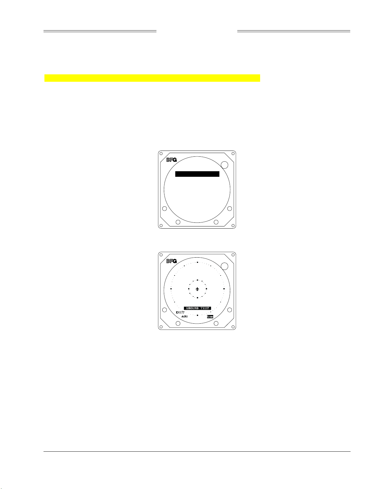
Preliminary
SKY899
Installation Manual
The calibration value (000-359) is derived from a variety of measurements. Specific values are meaningless
however, in a failed TRC, a varying spread may indicate problems with the directional antenna system
(antenna, cables, or connectors) or the TRC.
If the calibration failed, the message “Calibration Failed!” will be displayed.
4.4.4. Ground Test
Ground Test initializes the system for on-the-ground testing. In this configuration, the barometric
altimeter is simulated to 50,000 ft, heading simulated to 0 degrees, and the radar altimeter simulated to
2,500 ft. Ground test menu is accessed by selecting that option from the Service Menu (i.e., press SEL with
Ground Test highlighted).
The Ground Test screen displays the following:
BRT
Ground Test
Perform Ground Test
OFF
EXIT
Selecting Perform Ground Test initializes the ground test software and displays the following:
SEL
OFF
BRT
NOTES
1. When the system is set to GROUND TEST, the barometric altimeter is
simulated to 50,000 ft and the heading simulated to 0 degrees.
2. Ground test is available only if the squat switch input indicates aircraft is on
the ground.
3. When the system is set to GROUND TEST, the radio altimeter simulated to
2,500 ft.
4-15
Rev. A
Page 88

Preliminary
SKY899
Installation Manual
The buttons perform the following operations in this mode:
EXIT - causes the system to return to the Information Menu.
Soft-key (2) - toggles the system through the above (ABV), normal (NRM), below (BLW), and
unrestricted (UNR) altitude display modes. It is labeled to indicate current mode (i.e.,
ABV, NRM, or BLW).
Soft-key (3) - toggles the display range between 2, 6 and 15nm. It is labeled to indicate current range
(i.e., 2nm, 6nm or 15nm).
Soft-key (4) - is not used.
4.4.5 Configuration Management
Configuration Management menu allows you to save system configuration to a compact flash, retrieve
system configuration from a compact flash, or restore system configuration to factory defaults. To access
configuration management, select it from the Service Menu.
The Configuration Management screen displays the following:
BRT
Config Management
Archive to CF
Retrieve from CF
Restore Factory Defaults
OFF
EXIT
NEXT
SEL
PREV
4-16
Rev. A
Page 89
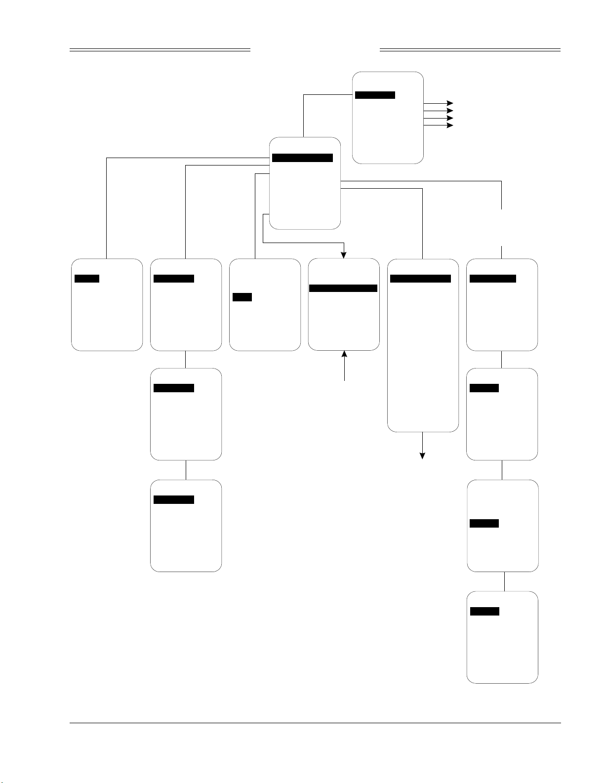
Preliminary
SKY899
Installation Manual
Setup
Information
Calibration
Ground Test
Config Management
Setup
Aircraft Type
Antenna System
Audio Level
Communication Ports
Avionics Equipment
EXIT
SERVICE MENU
NEXT
PREV
SEL
Information Menu Sheet 3 of 3
Calibration Menu Sheet 3 of 3
Ground Test Menu Sheet 3 of 3
Configuration Management
Menu Sheet 3 of 3
Aircraft Type
*None*
Fixed Wing
Rotor Craft
EXIT
NEXT
PREV
Top Antenna
*NY156 Directional*
Bottom Antenna
[None]
EXIT
SEL
*None*
NY164 Directional
NY156 Directional
EXIT
*None*
NY164 Directional
NY156 Directional
Antenna System
NEXT
Top Antenna
NEXT
Bottom Antenna
PREV
PREV
SEL
SEL
Volume
[50%]
Up
Down
Test
EXIT
NEXT
EXIT
Audio Level
PREV
NEXT
PREV
Changes have been made!
Save Changes
Revert to Old Settings
SEL
NEXT
Screen appears
when exiting Setup
menu and changes
have been made
SEL
Save or Revert
PREV
Equipment
Browse All Avionics
GPS Nav
[Gama]
Magnetic Heading
[None]
Barometric Altitude
[None]
Radio Altitude
SEL
[None]
Landing Gear
[None]
Weight-On-Wheels
[None]
Audio Suppression
[None]
External Display
[None]
EXIT
NEXT
Avionics Equipment
submenu on sheet 2 of 3
PREV
Please wait... will
be displayed while
autodetect is being
performed
Arinc 429 Receivers
Autodetect
Ch. 1: Multi 100 kHz
Ch. 2: None 100 kHz
Ch. 3: None Auto
Ch. 4: None Auto
Ch. 5: None Auto
EXIT
Type:
Speed: 100 kHz
SEL
EXIT
None
*ADC*
AHRS
*GPS*
Rad Alt
NEXT
Arinc 429 Rx Ch 1
NEXT
Equipment Type
ADC
GPS
PREV
PREV
SEL
SEL
EXIT
NEXT
SEL
PREV
EXIT
NEXT
12.5 kHz
100 kHz
NEXT
PREV
Speed
PREV
Figure 4-3. Service Menu Tree (Sheet 1 of 3)
SEL
SEL
4-17
Rev. A
Page 90
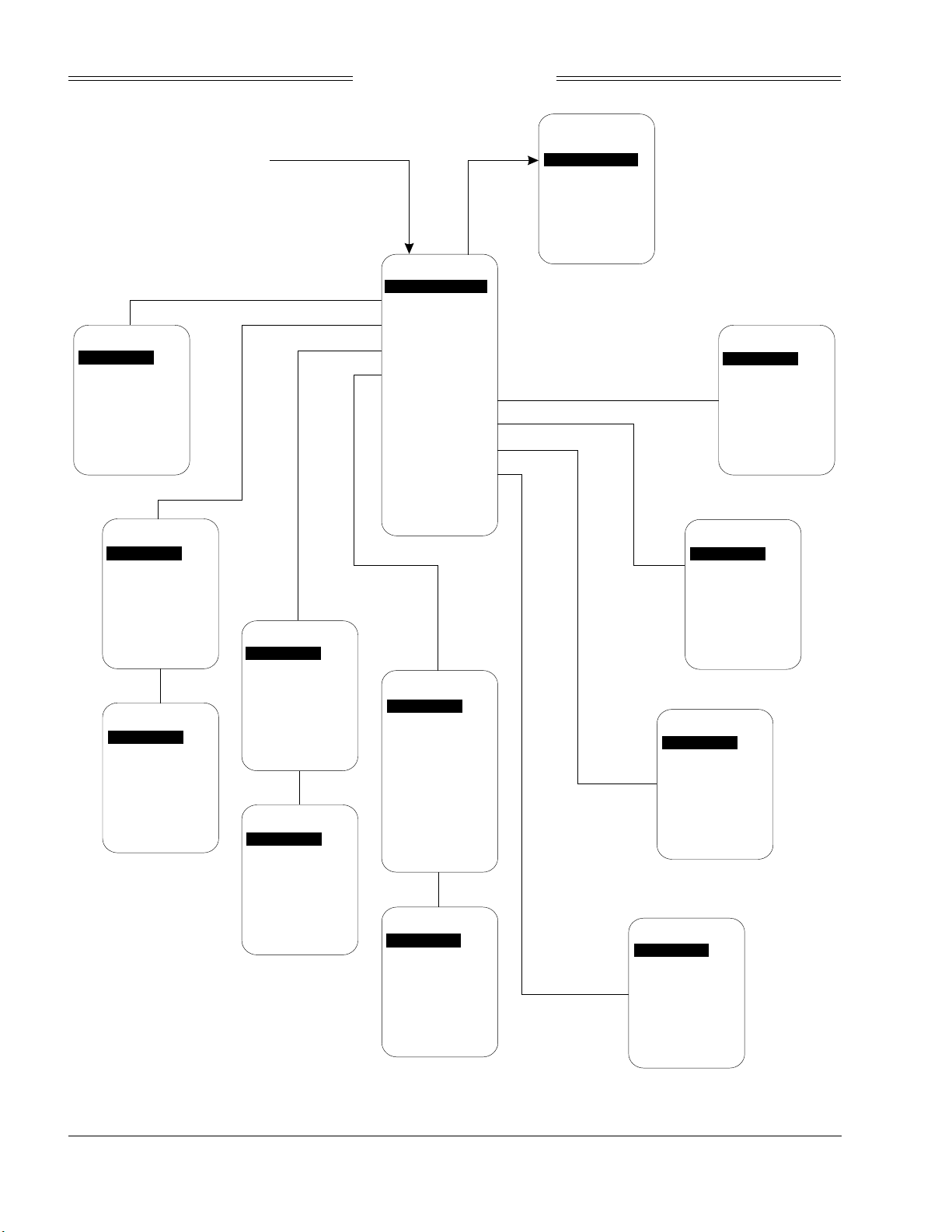
Preliminary
Avionics Equipment Submenu
from Sheet 1 of 3
SKY899
Installation Manual
No Chan Assigned
Choose a channel
Ch.1: None 100 kHz
Ch.2: Multi 100 kHz
Ch.3: None 100 kHz
Ch.4: None 100 kHz
Ch.5: None 100 kHz
Menu appears when
ARINC 429 equipment has
been selected, but not
assigned to a channel via
the Communication Ports Menu
GPS Nav
*None*
GAMA
ARINC 743A
EXIT
NEXT
*None*
Synchro Compass
AHRS
EXIT
Heading Valid Line
*None*
Valid Low
Valid High
EXIT
SEL
PREV
Magnetic Heading
NEXT
NEXT
PREV
PREV
SEL
SEL
Barometric Altitude
*None*
ADC
Encoding Altimeter
EXIT
NEXT
*None*
ARINC 429
PREV
ADC
SEL
Equipment
Browse All Avionics
GPS Nav
[Gama]
Magnetic Heading
[None]
Barometric Altitude
[None]
Radio Altitude
[None]
Landing Gear
[None]
Weight-On-Wheels
[None]
Audio Suppression
[None]
External Display
[None]
EXIT
NEXT
Radio Altimeter
*None*
Arinc429
Arinc 552
Arinc 552A
Bonzer Mark 10X
Collins ALT-50
Collins ALT-55
King KRA10/10A
King KRA 405
Sperry AA-100
Terra TRA 3000
EXIT
NEXT
PREV
PREV
SEL
SEL
EXIT
NEXT
PREV
SEL
Audio Suppression
*None*
Valid Low
Valid High
EXIT
Landing Gear
*None*
Valid Low
Valid High
EXIT
Weight-On-Wheels
*None*
Valid Low
Valid High
EXIT
NEXT
NEXT
PREV
NEXT
SEL
PREV
SEL
PREV
SEL
4-18
Rev. A
EXIT
NEXT
PREV
SEL
Rad Alt Valid Line
*None*
Valid Low
Valid High
EXIT
NEXT
PREV
SEL
Figure 4-3. Service Menu Tree (Sheet 2 of 3)
External Display
*None*
Standard Type1
Sextant Type2
Sextant CG
Forestry Serv
Collins EFIS Type1
EXIT
NEXT
PREV
SEL
Page 91
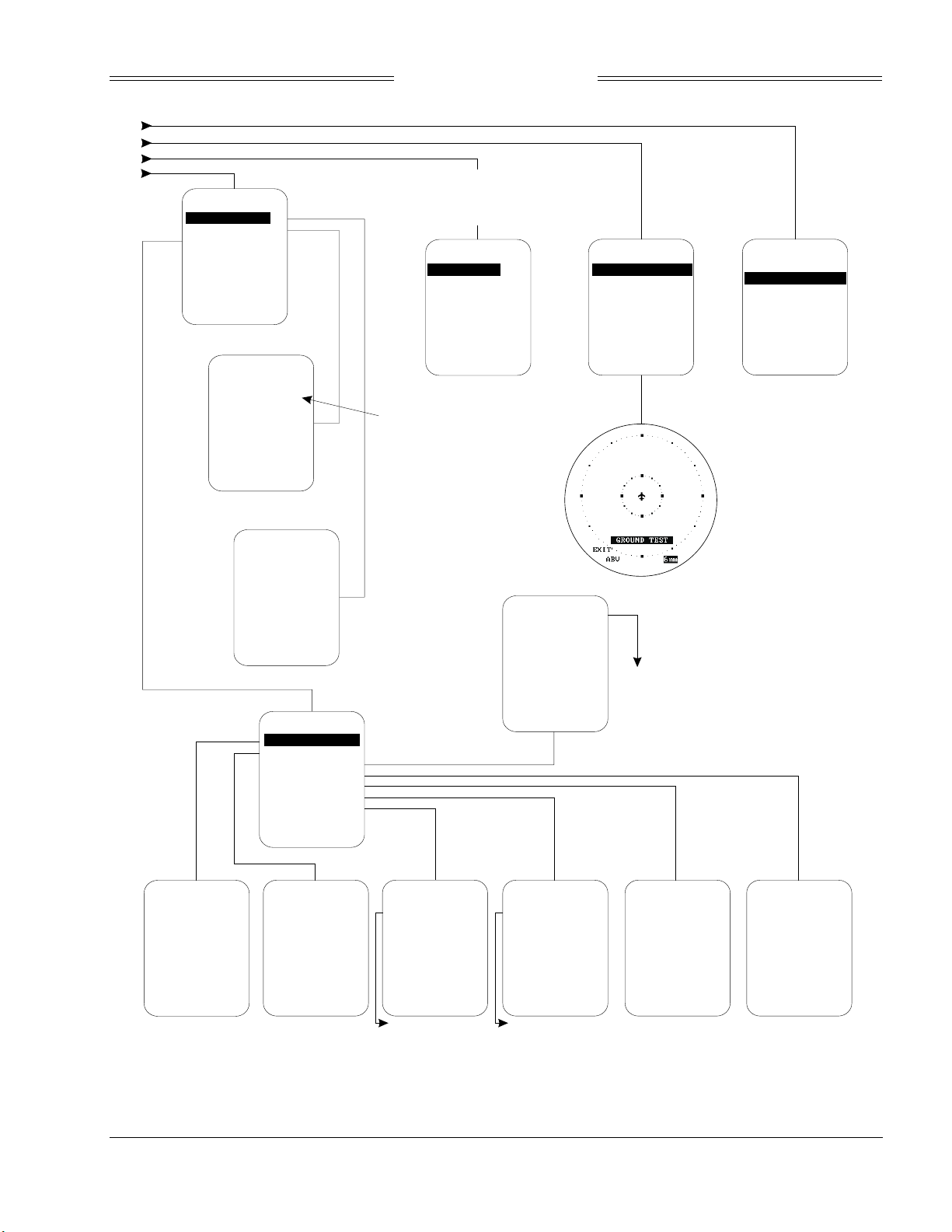
Preliminary
From Service Menu Sheet 1 of 3
Information
Software Version
System Log
Data Monitor
EXIT
NEXT
24 12
##
##
##
EXIT
SEL
PREV
System Log
/22/00 12:24:35
Software Error
MM/dd/yy hh:mm:ss
MM/dd/yy hh:mm:ss
MM/dd/yy hh:mm:ss
PREV
SEL
NEXT
SKY899
Installation Manual
SKY899 Antenna Calibration
in Process... will be displayed
while calibration is being
performed
Calibration
Top Antenna
Bit Phase: 131.10 degs
Bottom Antenna
Bit Phase: Invalid
EXIT
EXIT
NEXT
NEXT
With an Error highlighted
pressing SEL will
cause error description
to appear
PREV
PREV
SEL
SEL
Ground Test
Perform Ground Test
EXIT
SEL
Config Management
Archive to CF
Retrieve from CF
Restore Factory Defaults
EXIT
NEXT
PREV
SEL
ARINC 429 Receivers
Ch 1: Multi high
parity: xxxxx
Ch 2: None high
parity: 0
Ch 3: None Auto
parity: 0
Ch 4: None Auto
parity: 0
Ch 5: None Auto
parity: 0
EXIT
Software Version
SKYHP Vx.x
EXIT
Data Monitors
ARINC 429
Antenna Calibration
Barometric Altitude
Discrete Values
GPS Nav
Mag Heading
Rad Altitude
EXIT
NEXT
Data Monitor
Antenna Calibration
Top Antenna
Cal. Phase: 129.76 deg
Cur. Phase: 130.10 deg
Cur. Amp: -80.00 deg
Bottom Antenna
invalid
EXIT
PREV
SEL
Data Monitor
Rad Alt
(Arinc 429)
Validity: Valid
Altitude: 4005 ft
EXIT
(Bonzer Mark 10X)
Sense: Active Low
Validity: Valid
Altitude: 39 ft
Data Monitor
Baro Alt
(Encoding Altimeter)
Validity: Valid
Altitude: 1000 ft
A4=0 B4=0 C4=0 D4=0
A2=0 B2=1 C2=1 D2=0
A1=0 B1=1 C1=0 D1=0
EXIT
Data Monitor
Mag Heading
(Synchro Compass)
Sense: Active Low
Validity: Valid
Heading: 29.877 degs
EXIT
(AHRS)
Mag Heading: 29.998 degs
True Heading: 35.002 degs
Status: Valid
(ADC)
Validity: Valid
Altitude: 1000 ft
Data Monitor
GPS Nav
(GAMA)
Lat 42.308 deg
Lon -82.020 deg
Trk invalid
Spd invalid
EXIT
Data Monitor
Discretes
WOW sense: Active Low
WOW state: on grnd
Gear sense: Active Low
Gear state: down
Audio sense: Active Low
Audio state: suppress
EXIT
Figure 4-3. Service Menu Tree (Sheet 3 of 3)
4-19
Rev. A
Page 92

Preliminary
SKY899
Installation Manual
4.5 TROUBLESHOOTING
Table 4-1 is intended to assist trained electronic technicians to determine which assembly is inoperative.
Do the corrective action steps in the order described. Use the Service Menu (refer to paragraph 4.4) as an
aid in fault isolation. Information available from the service menu can help identify conditions that need to
be resolved. If interfaced to an alternate display service menu must be accessed via an RS-232 terminal
device, see Appendix E for operating instructions.
Table 4-1. Fault Isolation
SYMPTOM CORRECTIVE ACTION
Display remains dark after SKY899 is powered ON.
Display is distorted.
Incorrect response to buttons (soft-keys).
SKY899 will not enter service menu.
The self-test successfully completes without audio
annunciation.
SKY899 Failed.
Self-test does not execute. Aircraft is on the ground.
The display cannot be switched between SKY899 and the
WX-1000. Both systems are installed.
WX-1000 processor has been removed for service;
SKY899 fails to operate.
a. Check position of the WX-1000 maintenance switch
(NORMAL/OVERRIDE).
b. Reset circuit breaker if it is tripped.
c. Check aircraft power source.
d. Check connection to WX-1000 processor, if installed.
e. Check power input at TRC mating connector.
P8-A +28V (18 - 32 V dc PWR)
P8-B +28V_RET (AIRCRAFT PWR RETURN)
f. Check cables connected to display.
g. Replace Display.
Check for interference from aircraft systems.
Check soft-key wiring inside display cable and WX-1000
processor cable (if installed).
a. Check soft-key wiring.
b. If using an alternate display device the soft-key's
needed for accessing service menu from the WX1000/SKY497 display are not connected.
c. If using an alternate display service menu must be
accessed with an RS-232 terminal device by typing the
menu command. (Appendix E)
a. Check headphones/speaker and aircraft audio panel
switch settings.
b. Check volume level and run audio test in service menu.
c. Check cables connected to TRC.
Audio Alert Output:
P1-89 (AUDIO_H - 600-Ohm)
P1-90 (AUDIO_L - 150-Ohm)
P1-91 (AUDIO_C - Common)
a. Check system log (para 4.4.2) for errors. Error
messages are detailed in para 4.6.
b. Replace TRC.
a. If standby screen is displayed, check soft-key wiring
inside display cable and WX-1000 processor cable
(if installed).
b. Check squat switch connection to the TRC and the
weight-on-wheels configuration in service menu.
Squat Switch Input: P1-24
a. Check circuit breakers. Reset if tripped.
b. Check position of the WX-1000 maintenance switch
(SW2). It should be set to the NORMAL position.
c. Check wiring of the SKYWATCH/
mode switch (para 2.7.3 and figure 2-2).
Check position of the WX-1000 maintenance switch
(NORMAL/OVERRIDE). When the WX-1000 has been
removed for service, it should be set to the OVERRIDE
position. This switch may be located in the avionics bay.
Stormscope
display
4-20
Rev. A
Page 93

Preliminary
SKY899
Installation Manual
Table 4-1. Fault Isolation (Continued)
SYMPTOM CORRECTIVE ACTION
SKY899 paints itself as a target (e.g., TA). a. Verify suppression bus shielded cable is grounded
correctly at both ends.
b. Connect an oscilloscope to the suppression bus and
verify that the SKY899 suppression pulse (100 µs ±5 µs)
exceeds +15 V dc.
c. If less than +15 V dc, the suppression bus is
overloaded.
d. Check all equipment connected to the bus.
e. Repair/replace the offending device.
SKY899 TRC899 has been removed for service; the WX1000
Stormscope
fails to operate.
4.6 ERROR MESSAGES
SKY899 firmware is designed to generate error messages associated with a particular condition or step in
the program. The 20 most recent errors detected by the system are saved in the System Log (see para
4.4.2.2). For your convenience, in table 4-2, we have listed the error messages that have been associated
with SKY899 installations. Where appropriate, procedures that may assist in resolving installation
problems are provided. When a severe error occurs SKY899 will fail.
Check the adapter plug (see para 4.7). If the TRC899 is
removed for service, an adapter plug is required to permit
continued operation of the WX-1000.
Table 4-2. Installation Related Error Messages
ERROR NO. MESSAGE REMARKS
ERROR 06 I2C Bus Error a. Configuration module is present, however the BUS communication (SDA or SCL) is
incorrect check associated wiring.
b. Replace TRC.
c. Replace configuration module.
ERROR 07 Config Module Error a. Configuration module is not found check associated wiring.
b. Replace TRC.
c. Replace configuration module.
ERROR 10 Compact Flash Error a. Unable to read the compact flash information correctly, verify compact flash is inserted
into J12 correctly.
b. Try a different compact flash.
c. Replace TRC.
ERROR 14 RF Amplitude Error a. Check directional antenna and associated cables.
b. Calibrate directional antenna (para 4.4.3)
NOTE
ERROR 15 RF Angle Error a. Check directional antenna and associated cables.
ERROR 17 Mag Var Table Error a. Unable to read the compact flash information correctly, verify compact flash is inserted
Ensure transponder is in standby and DME is OFF while doing calibration
c. Cycle power and run pilot initiated self-test.
b. Calibrate directional antenna (para 4.4.3)
NOTE
Ensure transponder is in standby and DME is OFF while doing calibration
c. Cycle power and run pilot initiated self-test.
into J12 correctly.
b. Try a different compact flash.
c. Replace TRC.
4-21
Rev. A
Page 94

Preliminary
SKY899
Installation Manual
Table 4-2. Installation Related Error Messages (Continued)
ERROR NO. MESSAGE REMARKS
ERROR 20 Barometric Input Error a. Check altimeter source. Is the unit turned on and been given enough time to warm up.
b. Cycle power.
c. Ensure that barometric altitude input is from only one source (gilham code or ARINC-
429).
d. Encoded inputs can be checked from the barometric altimeter data m onitor screen (para
4.4.2.3).
e. Using the service menu, verify barometric source configuration and altitude information
(para 4.4.2.3).
f. Check wiring associated with altimeter source.
ERROR 21 GPS Input Error a. Check GPS source is it turned on and locked onto satellites.
b. Using the service menu, verify configuration (speed and equipment type) is set correctly.
c. Check ARINC-429 wiring associated with GPS.
ERROR 22 Heading Input Error No heading input being received (ARINC-429 or synchro compass).
a. Check heading source.
b. Using the service menu, verify heading setup in Mag Heading data monitor (para
4.4.2.3).
c. If the heading signals become valid, the system will recover automatically.
d. Check wiring associated with heading input.
ERROR 23 Synchro Input Error Invalid synchro compass input (XYZ signals or 400 Hz reference).
a. Check heading source.
b. Using the service menu, verify heading setup in mag heading data monitor (para 4.4.2.3).
c. If the heading signals become valid, the system will r ecover automatically.
d. Check wiring associated with synchro compass input.
ERROR 29 System Config Error a. SKY899 requires a barometric altitude input in order to operate. Verify a source has been
selected in service menu.
b. Check wiring associated with configuration module if error reoccurs replace configuration
module.
The error messages in table 4-3 are used by factory technicians in determining what actions may have
preceded a system failure. These messages do not necessarily indicate a current system failure and are
provided for information only. Should the installer observe these messages in the error log without a
SKY899 Failed message during normal operation, no service action is required.
Table 4-3. Informational Error Messages
ERROR NO. MESSAGE ERROR NO. MESSAGE
ERROR 01 Boot Error ERROR 16 Antenna Sel. Unit Error
ERROR 02 ROM Memory Error ERROR 18 ARINC 429 Comm Error
ERROR 03 RAM Memory Error ERROR 19 Serial Comm Error
ERROR 04 Watchdog Error ERROR 24 Software Error
ERROR 05 Bus Fault Error ERROR 25 Operating Sys Error
ERROR 08 Unused Interrupt Error ERROR 26 Video Controller Error
ERROR 09 I/O Board Error ERROR 27 Video Memory Error
ERROR 11 Power Supply Error ERROR 28 NVRAM Error
ERROR 12 RF Failure Error ERROR 30 System Test Error
ERROR 13 RF Transmitter Error
4-22
Rev. A
Page 95
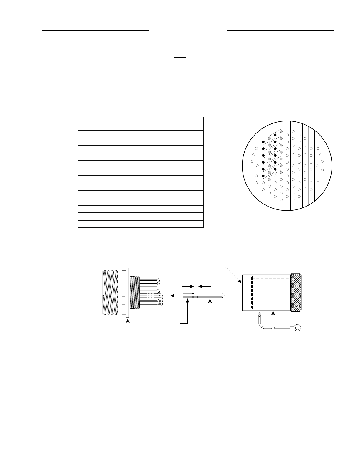
Preliminary
SKY899
Installation Manual
4.7 TRC899/WX-1000 ADAPTER PLUG
An adapter plug can be used to by-pass SKY899 only if a WX-1000 Stormscope system is installed. The
adapter will permit continued operation of the WX-1000 if the TRC899 is removed for service. It can also
be used as a troubleshooting tool when attempting to isolate a problem to either or both systems.
The adapter plug mates with P1. It can be purchased from BFGoodrich Avionics Systems (P/N 805-11910-
001) or fabricated locally from the details provided in figure 4-4.
ADAPTER PLUG CONNECTIONS
JUMPER PINS FUNCTION
825DPWR+15
926DPWR-15
10 27 DSPLY_GND
11 28 HSYNC_+
12 29 HSYNC_-
13 30 VSYNC_+
22 41 VSYNC_-
16 35 VIDEO_+
17 36 VIDEO_-
18 37 SFTKEY1
19 38 SFTKEY2
20 39 SFTKEY3
21 40 SFTKEY4
NOTE
APPLY LOCTITE TO THE INTERNAL THREADS
OF THE BACKSHELL PRIOR TO ASSEMBLY.
®
PIN INSERT VIEW
35
25
16
8
1
2
3
7
15
24
34
ADAPTER PLUG JUMPER INSTALLATION
56
46
67
77
86
94
100
93
55
45
85
76
66
+0.07
0.10
-0.00
CRIMP PIN
CONNECTOR
MIL # D38999/20FH35PB
JUMPER
#22 AWG WIRE
SHORTING CAP
BACKSHELL
GLENAIR #340HS002M23-2H12A
Figure 4-4. Adapter Plug Assembly
Rev. A
4-23
Page 96

Preliminary
SKY899
Installation Manual
4.8 DISPOSITION OF FAILED ITEMS
Return defective components to your authorized BFG Avionics Systems dealer or to::
BFG Avionics Systems
Attn: Customer Service
5353 52nd Street, S.E.
Grand Rapids, MI USA 49512
If available, pack components in their original shipping container. If the original container is not available,
pack them as follows:
CAUTION
Do not use desiccant crystals when packaging electronic assemblies. Since the
assembly must be packed tightly, crystals in bag form cannot be used. The use of
loose crystals may cause unnecessary damage resulting in a cleaning problem.
1. Ensure that nonconductive covers/caps are installed on the exposed terminals of cable connectors on
the display, TRC, and antenna.
2. The display and TRC contain electrostatic discharge sensitive (ESDS) parts and must be wrapped in
static protective materials.
3. Wrap with bubble pack. Secure bubble pack with reinforced tape.
4. Place assembly in a cardboard box.
5. Wrap any accessories in tissue and place in the box. Fill spaces with bubble pack.
6. Put a letter on top of bubble pack. The letter must contain:
• Your name, address, and telephone number.
• Purchase order number.
• Description of component including, when applicable, model and serial number.
• Date of purchase.
• A brief description of the difficulty.
• Type of display and radar altimeter.
• Copy of error log, if available.
7. Shut box and seal with reinforced tape.
8. Attach packing list to outside of box.
4-24
Rev. A
Page 97

Preliminary
SKY899
Installation Manual
APPENDIX A
SKY899 INTERFACE
SIGNAL & CABLE CHARACTERISTICS
A.1 INTRODUCTION
This appendix defines the electrical characteristics of all input/output signals to the TRC899 and the labels
for the ARINC-429 data bus. Sufficient data is included to perform an electrical load analysis for the
aircraft. The interface characteristics contained in this appendix are fully compatible with ARINC
specifications where noted. Connection information identifies connector-pin and signal names as they
appear on interconnect wiring diagram, figure A-1 shows P1 connector pin locations and signal names.
NOTE
External isolation diodes are not required and SHOULD NOT be installed.
A.2 ELECTRICAL CHARACTERISTICS
SIGNAL CHARACTERISTICS
Altitude (Gilham Code) / These uncorrected barometric signals are Gilham code (or gray code)
Encoding Altimeter Input inputs coming from an airdata computer or encoding altimeter (see
paragraph 2.11). These 11 lines may be connected in parallel with the
aircraft transponder. If the aircraft is equipped with selectable altitude
encoders, connect the altitude inputs so that SKY899 is always connected
to the selected encoder. (Reference ARINC 572-1.)
NOTES
1. Only one altimeter input source (gray code or ARINC-429, not both)
should be connected. The altimeter input should be from the same
source that is interfaced with the transponder or at least as accurate as
that source, i.e., ± 125 ft.
2. If the aircraft has switched encoders that use 28V RETURN or
AIRCRAFT GROUND as reference for encoder selection, then
ALT_COMMON (P1-72) should be left unconnected.
3. If altitude D2 is not used P1-70 should remain unconnected.
CONNECTION Connector-Pin
P1-56 ALT_A1
P1-57 ALT_A2
P1-58 ALT_A4
P1-59 ALT_B1
P1-60 ALT_B2
CABLE Minimum 22 AWG wire for lengths up to 30 ft.
VOLTAGE +30 V input max.
CURRENT <1 mA sourced per line.
FREQUENCY <100 Hz
SOURCE Z >10 kΩ per line.
MAX CAPACITANCE <20 pF per line.
P1-61 ALT_B4
P1-67 ALT_C1
P1-68 ALT_C2
P1-69 ALT_C4
P1-70 ALT_D2
P1-71 ALT_D4
P1-72 ALT_COMN
Signal Name
A-1
Rev. A
Page 98

Preliminary
SKY899
Installation Manual
SIGNAL CHARACTERISTICS
Antenna Top Directional SUM (SIGMA) Port (Blue)
CONNECTION Connector
J9 - TNC SUM
CABLE Cable attenuation must not exceed 2.5 dB, VSWR
1.5:1. Refer to paragraph 2.6.1.
Impedance: 50 Ω
Antenna Top Directional BIT PROBE Port (Black)
CONNECTION Connector
J10 - BNC BIT
CABLE Cable attenuation must not exceed 6 dB, VSWR
1.5:1. Refer to paragraph 2.6.1.
Impedance: 50 Ω
Antenna Top Directional DIFFERENCE (DELTA) Port (Red)
CONNECTION Connector
J11 - TNC DIFFERENCE
CABLE Cable attenuation must not exceed 2.5 dB, VSWR
1.5:1. Refer to paragraph 2.6.1.
Impedance: 50 Ω
ARINC-429 External Interface The SKY899 has seven ARINC-429 receivers and three transmitter
(paragraph 2.9). Four of the channels are paired internally and can
operate at either low speed (12.5 kHz) or high speed (100 kHz). However,
the paired channels must be set to the same speed (see tables A-1 and A-
2). The transmitters operate only at high speed (100 kHz).
Signal Name
Signal Name
Signal Name
The first ARINC-429 transmitter (A429TX1) is intended to provide the
capability to interface with alternate display device. The second and third
ARINC-429 transmitters (A429TX2 & TX3) are a future option.
Five of the ARINC-429 receivers can be used to input data from other
avionics systems. The sixth and seventh receivers are not used at this time
(future option).
NOTES
1. The radio altimeter must provide full range output between 0 and
2500 feet. Not all altimeters provide this full range output. The full
range output can sometimes be obtained as a mod to the radio
altimeter . Check with the specific altimeter manufacturer for
compatibility and availability of modification, if necessary.
2. The TRC can accept Radio Altimeter input from ARINC-429 or DC
analog source. The Barometric Altitude can be ARINC-429 or
Gilham Code. The Magnetic Heading can be ARINC-429 or Synchro
(XYZ). Select only one source for each aircraft input.
3. If 429 barometric altitude is used, it should be from the same source
that is interfaced with the transponder or it must be at least as
accurate as that source, i.e., ± 125 ft.
4. Receive channels 1 and 2 must be set to the same speed (12.5 or 100
kHz). Receive channels 3 and 4 must be set to the same speed (12.5
or 100 kHz). Channel 5 is independent of the other receivers and
can be to 12.5 or 100 kHz.
A-2
Rev. A
Page 99

Preliminary
SKY899
Installation Manual
SIGNAL CHARACTERISTICS
ARINC-429 External Interface CONNECTION Connector-Pin
(Continued) P1-54 A429RX1_A Ch. 1 line A
P1-55 A429RX1_B Ch. 1 line B
P1-62 A429RX2_A Ch. 2 Line A
P1-63 A429RX2_B Ch. 2 Line B
P1-64 A429RX3_A Ch. 3 Line A
P1-65 A429RX3_B Ch. 3 Line B
P1-73 A429RX4_A Ch. 4 Line A
P1-74 A429RX4_B Ch. 4 Line B
P1-75 A429RX5_A Ch. 5 Line A
P1-76 A429RX5_B Ch. 5 Line B
P1-83 A429RX7_A Ch. 7 Line A
P1-84 A429RX7_B Ch. 7 Line B
P1-81 A429RX8_A Ch. 8 Line A
P1-82 A429RX8_B Ch. 8 Line B
P1-42 A429TX1_A Ch. 1 Line A
P1-43 A429TX1_B Ch. 1 Line B
P1-44 A429TX2_A Ch. 2 Line A
P1-45 A429TX2_B Ch. 2 Line B
P1-52 A429TX3_A Ch. 3 Line A
P1-53 A429TX3_B Ch. 3 Line B
Audio (Alert) Output This output is directly compatible with industry standard audio panels
(see paragraph 2.10).
Signal Name
NOTE
Audio output from the TRC is transformer isolated.
This output is disabled when a terrain warning alarm is detected (see
paragraph 2.7.1)
CONNECTION Connector-Pin
P1-89
P1-90
P1-91 (AUDIO_C) Audio Common
CABLE Minimum 22 AWG twisted shielded pair cable for
lengths up to 30 ft.
POWER 40 mW into a 600 Ω load. Audio level is adjustable
via service menu.
FREQUENCY 0 - 3.0 kHz
Audio Inhibit This input senses a terrain warning alarm and temporarily disables the
(Terrain Warning System - SKY899 audible alert messages until the warning clears (see paragraph
GPWS) The input can be either a constant flag signal or an alternating flag
LOAD Z Selectable 150 or 600 Ω
2.7.1).
output. The flag must be cleared for five (5) seconds before the TRC
accepts a "NO ALARM" condition and restores audible alerts.
AIRCRAFT IS NOT EQUIPPED WITH TERRAIN WARNING SYSTEM
INPUT UNCONNECTED
If the aircraft is equipped with terrain warning system (GPWS), it
must be connected to the TRC.
.
NOTE
Signal Name
(AUDIO_H) - 600 Ω
(AUDIO_L) - 150 Ω
IF THE
, LEAVE THIS
A-3
Rev. A
Page 100

Preliminary
SKY899
Installation Manual
SIGNAL CHARACTERISTICS
CONNECTION Connector-Pin
P1-34 (GPWS)
CABLE Minimum 22 AWG wire for lengths up to 30 ft.
VOLTAGE WARNING: 0 V dc to +2.5 V dc (Aircraft Ground).
NO WARNING: +9 V dc to +30 V dc or open.
CURRENT <5 mA sourced.
Debug Port
Heading Input These connections from the aircraft heading source (ARINC 407 & 407-1
(XYZ Synchro) Synchro System Manual) allow the unit to rotate the displayed data as the
NO CONNECTION TO EXISTING AIRCRAFT WIRING. The Debug Port (RS-232) is
used for laptop interface to support system setup, post installation
checkout and troubleshooting. The port defaults to the following settings:
Baud Rate 19,200
Parity: None
Data Bits 8
Stop Bits 1
No handshaking
CONNECTION Connector-Pin
J7-2 DIAG_RX
J7-3 DIAG_TX
J7-5 DIAG_GND
J7-7 CTS
J7-8 RTS
aircraft turns. See Heading Flag in this appendix for flag input
specifications.
X(S1), Y(S3), Z(S2)
FREQUENCY Min: 50 Hz
Max: 1500 Hz
VOLTAGE
Min: 5.0 V ac rms (w/reduced angular resolution.)
Max: 14.0 V ac rms (external padding required for
INPUT IMPEDANCE >50 kΩ
Signal Name
Signal Name
higher levels.)
A-4
Rev. A
CONNECTION Connector-Pin
P1-46 HEADING_X
CABLE See paragraph 2.6.4.
H and C (high and low reference)
FREQUENCY Min: 50 Hz
VOLTAGE Min: 3 V ac rms
INPUT IMPEDANCE >50 kΩ
CONNECTION Connector-Pin
CABLE See paragraph 2.6.4.
P1-47 HEADING_Y
P1-48 HEADING_Z
Max: 1500 Hz
Max: 35 V ac rms
P1-49 HEADING_H
P1-50 HEADING_C
Signal Name
Spec says 400 Hz ±20%
Signal Name
 Loading...