

Kyosho Presto, Vanning Instruction Manual
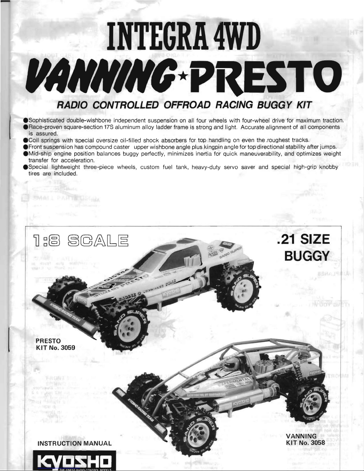
INTEGRA4WD
"""'"(J*PitEST'O
RADIO CONTROLLED OFFROAD RACING BUGGY KIT
.Sophisticated
double-wishbone independent suspension
on
all four wheels with four-wheel drive for maximum traction .
• Race-proven square-section
17S
aluminum alloy ladder frame is strong and light. Accurate alignment of all components
is assured .
• Coil springs with special oversize oil-filled shock absorbers for top handling
on
even the .roughest tracks .
• Front suspension has compound caster upper wishbone angle plus kingpin angle for top directional stability after jumps .
• Mid-ship engine position balances buggy perfectly, minimizes inertia for
quick
maneuverability, and optimizes weight
transfer for acceleration .
• Special lightweight three-piece wheels, custom fuel tank, heavy-duty servo saver and special high-grip knobby
tires are included .
PRESTO
KIT
No. 3059
INSTRUCTION
MANUAL
.21
SIZE
BUGGY
VANNING
KIT
No. 3058
"
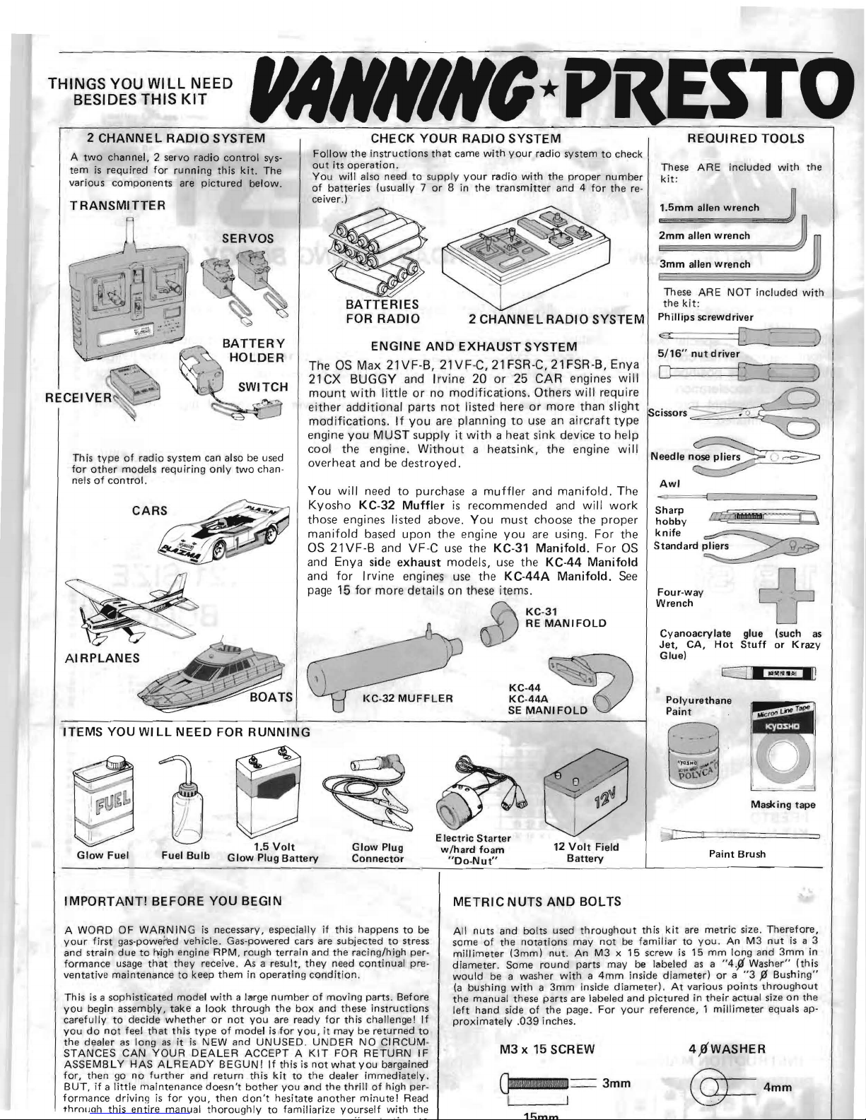
THINGS YOU
Will
NEED
BESIDES THIS
KIT
2
CHANNEL
RADIO
SYSTEM
A
twO
channel, 2 servo radio control sys-
tem
is
required for running this
kit
_ The
various
components
are
pictured
below_
TRANSMITTER
This
type
of
radio system can also be used
for
other
models requ iring
only
two
chan-
nels
of
control.
ITEMS
YOU
WI
LL
NEED
FOR
RUNNING
Electric
Starter
1.5
Volt
Glow Plug
12
Volt
Field
w/hard
foam
Glow Fuel
Fuel Bulb Glow Plug Battery
Connector
Battery
"Do-Nut"
••
,.,*
PRESTO
CHECK
YOUR
RADIO
SYSTEM
Follow
the
instructions
that
came with
your
radio system
to
check
out
its
operation.
You will also need
to
supply
your
radio with
the
proper
number
of batteries (usually 7
or 8 in
the
transmitter
and 4 for
the
re-
ceiver.)
BATTERIES
FOR
RADIO
2
CHANNE L RADIO
SYSTEM
ENGINE
AND
EXHAUST
SYSTEM
The
as
Max
21VF-B,
21VF-C,
21
FSR-C,
21
FSR-B,
Enya
21
CX
BUGGY
and
Irvine
20
or
25
CAR
engines
will
mount
with
little
or
no
modifications.
Others
will
require
either
additional
parts
not
listed
here
or
more
than
slight
modifications_
If
you
are pla
nning
to
use
an
aircraft
type
engine
you
MUST
supply
it
with a heat
sink
device
to
help
cool
the
engine.
Without a heatsink,
the
engine
will
overheat
and
be
destroyed.
You
will
need
to
purchase a muffler
and
manifold.
The
Kyosho
KC-32
Muffler
is
recommended
and
will
work
those
engines
listed
above.
You
must
choose
the
proper
manifold
based
upon
the
engine
you
are
using.
For
the
as
21VF-B
and
VF-C
use
the
KC-31
Manifold.
For
as
and
Enya
side
exhaust
models,
use
the
KC-44
Manifold
and
for
Irvine
engines
use
the
KC-44A
Manifold.
See
page
15
for
more
details
on
these
items.
Cl)/
<2\
KC-31
RE
MANIFOLD
~'i
KC-44
KC-44A
~
SE MANIFOLD n
REQUIRED
TOOLS
These ARE included with
the
kit:
1.
5mm
allen wrench m
=!:=m"'m"""a=lIe"'n
"""w"'re"'n"'c
"'
h"""''''''''''''#; J
3mm
allen wrench
These ARE NOT included with
the
kit:
Phillips screwdriver
5/16"
nut
driver
Ot====L[=
=
~:-'
=)
Sharp
hobby
knife
~
Standard
~
Four-way
Wrench
~
Cyanoacrylate glue (such as
Jet,
CA,
Hot
Stuff
or
Krazy
Glue)
C II...
M
...
.,
Ip
Polyurethane
Paint
. .
~g
.
(1
(--"'
; ' I
\
~
;
. _
J.
Masking
tape
~
:=::r
====
=
Paint Brush
IMPORTANT!
BEFORE
YOU
BEGIN
A WORD OF WARNING
is
necessary, especially
if
this happens
to
be
your
first gas-powered vehicle. Gas-powered cars are subjected
to
stress
and strain
due
to
J-vigh
engine RPM, rough terrain and
the
raCing/high per-
formance usage th'
at
they
receive.
As
a result,
they
need continual pre-
ventative maintenance to keep them
in
operating
condition.
This
is
a sophisticated model with a large
number
of moving parts. Before
you
begin assembl.y,
take
a look through
the
box
and these instructions
carefully
to
decide
whether
or
not
you
are ready for this challenge!
If
you
do
not
feel
that
this
type
of
model
is
for
you,
it may
be
returned
to
the
dealer as long
as
it
is
NEW
and
UNUSED. UNDER NO CIRCUM-
STANCES
CAN
YOUR DEALER ACCEPT A KIT FOR RETURN IF
ASSEMB L Y HAS ALREADY BEGUN!
If
this
is
not
what
you
bargained
for,
then
go
no
further
and
return this
kit
to
the
dealer immediately.
BUT,
if
a little ma intenance
doesn't
bother
you
and
the
thrill
of
high per-
formance
driving
is
for
you,
then
don't
hesitate
another
minute! Read
thrnlJoh this entire manual thoroughly to familiarize yourself with
the
METRIC
NUTS
AND
BOLTS
All
nuts and bolts used
throughout
this kit are metric size. Therefore,
some
of
the
notations
may
not
be
familiar to
you.
An
M3
nut
is
a 3
millimeter (3mm) nut.
An
M3
x 15 screw
is
15 mm long and
3mm
in
diameter.
Some
round
parts may be labeled
as
a "4.ji Washer" (this
would be a washer with a
4mm
inside diameter!
or a "3
% Bushing"
(a
bushing with a
3mm
inside diameter).
At
various points
throughout
the
manual these parts are labeled and pictured
in
their
actual size
on
the
left hand side
of
the
page.
For
your
reference, 1 millimeter equals ap-
proximately
.039
inches.
M3 x 15
SCREW
4,9WASHER
O!ijilll!!!!I!!IM!!jj!!!!!!!!NI!!!\ij
I I
3mm
@=4mm
In addition
to
the damp
er
oil
and
different
ial oil (red liq uids)
cem
el
t, a the nut
s and bolts
of
the car WI
LL
eventually fall
you
will
also
find
a small tube labeled "screw
cement"
. This
out.
Use
this
type
of
cement
only
on the nuts and bolts. When
it
bluish
-g~ee
n
locking compo und should
be
used
on
all NUTS' calls
for
ceme
nt
in the manual,
use
an
"instant"
type
of
glue
AND
BOLTS in the car including those part s which are
ALREADY
~uch
as
Jet, CA or
Hot
Stuff.
ASSEM
BLED
to ensu
re reli
ability. If
you
do
not
use
the screw
iJ
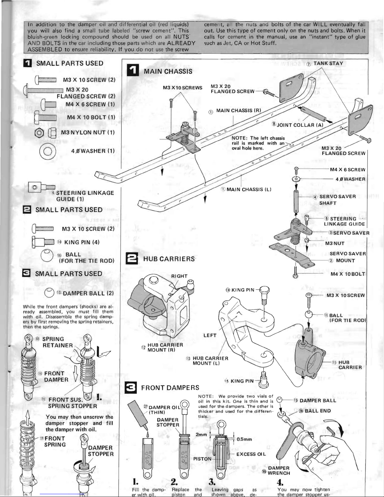
SMALL
PARTS USED
M3
X 10 SCREW (2)
~
~
iL
I "
11\
II
'
J~
A~3G~~~CREW
(2)I
111
1
~
0 II
M4 X 6SCREW
III
M4 X
lOBO
LT (1)
@
~
M3
NYLON
NUT
(1)
@
4,a'WASHER (1)
~
6
STEERING
LINKAGE
GUIDE
(1)
~
SMALL
PARTS USED
~
M3Xl0SCREW(2)
~
li
J>
KING
PIN (4)
M 1
30
BALL
U (FOR THE
TIE
ROD)
El
SMALL
PARTS USED
o
0'5;
, DAMPER
BALL
(2)
While thll
front
dampers
(shocks) are al·
ready a
ss
embled
, y
ou
must
fill
them
with
oil.
Disassemble the
spring
damp·
ers
by
first
removing
t he
spring
retainers,
then
the
springs.
11
1; SPRING
RETAINER
FRONT
SUS.
~
I
..
'
'Ii
FRONT
DAMPER
j]j,
SPRING STOPPER
You may then unscrew the
damper stopper and
fill
the damper
with
oil.
il~
FRONT
~
SPRING DAMPER
STOPPER
,
(j)
TANK
STAY
MAl
N CHASSIS
M3
X10SCREWS
I
~~
~~
JOINTCOL~AR(A)
~~./
_
l?
~.,.a"'<:r')·
~
/
NOTE:
The
left
chassis r
rail
is
marked
with
an
~
m
HUB
CARRIERS
t
'r-
--
i1
)
MOUNT
oval
hole
here. /__
M3 X 20
i
(0---
-
t
- - 0
SHAFT
@.-
M3NUT
)]
(':l
c:;lJ
MAIN
CHASSIS
(R)
(\
CD
"•
.,.,
~
f. /
-~
~
"'"
FLANGED
SCREW
M4X6SCREW
c
-
4.0'WASHER
SERVOSAVER
@
STEERING
LINKAGE
GUIDE
@
SERVO
SAVER
SERVOSAVER
@
HUB
CARRIER
MOUNT
(R)
LEFT
I
M4 X 10BOLT
M3 X 10SCREW
ill
HUB
CARRIER
EJ
FRONT
DAIVIPERS
'"
KINGPlN
~
NOTE : We
provide
two
vials
of
0-lfjl
DAMPER
BALL
ll
I
DAMPER
OIL
0
/
(THIN)
DAMPER
STOPPER
6
o 0
2.
oil
in
this
kit.
One
is
thin
and
is
u
sed
for
the
dampers. The
other
is
thi
ck er and used
for
the
differen·
tials.
EXCESS
OIL
.L
~
/([
8;
BALL
END
~
I.
4.
Fill
the
damp
- Replace
the
Leaving gaps
as
You
may
now
tighten
er
with
all. is
ton
a
nd
shown
above.
de·
the dam
er s
topper
us-
~
I
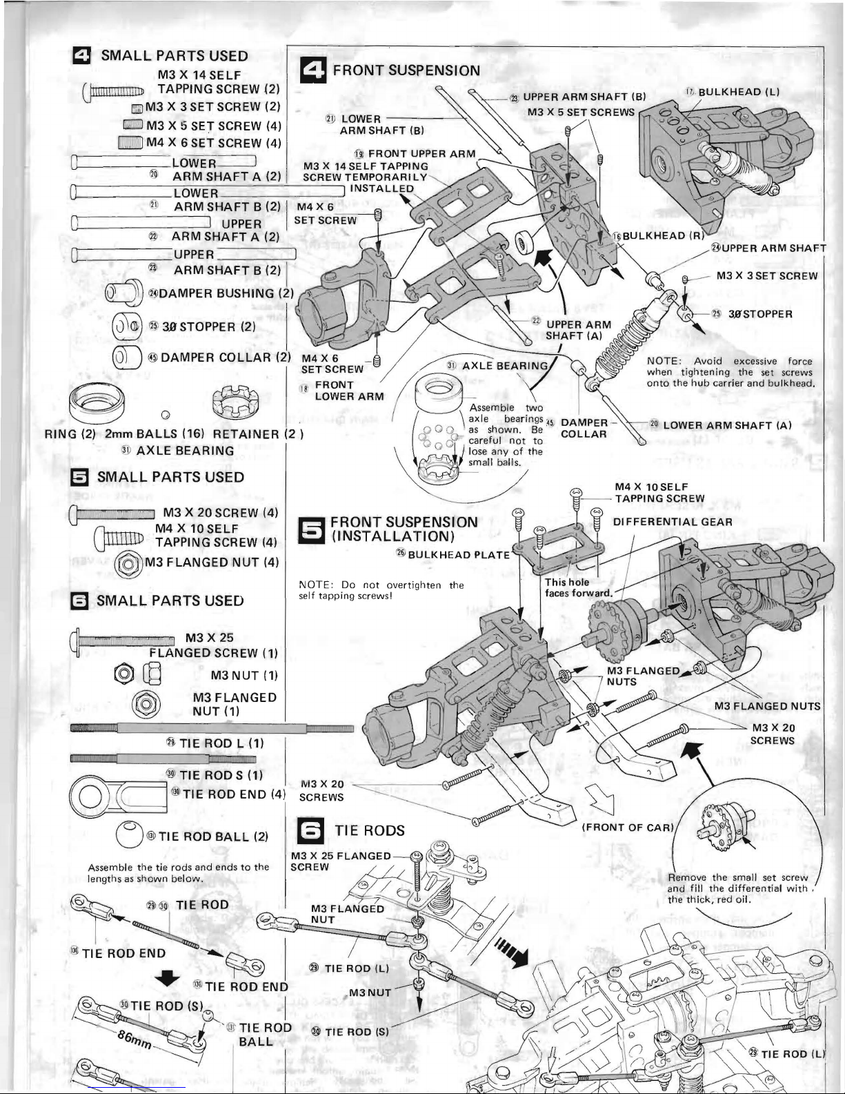
SMALL
PARTS USED
M3
X 14
SELF
Ullillil liI
'II
Ii
ilJJ
TAPPING SCREW m
[5;U)M3
X 3 SET SCREW (2)
IiliiEl
M3
X
ti
SET SCREW (4)
MlJ
M4 X 6 SET SCREW (4)
o -
LOWER=:==!
12~
ARM
SHAFT
A (2)
O=
___
----;:::-_UPPER
I
@
ARM
SHAFT
B
(2)
I
~
fI.J
"DAMPER
BUSHING
12)
'.\/
®
~
3.9'
STOPPER (2)
\];
@J
@DAMPER
COLLAR
(2)
@
o
~
~
18
FRONT
LOWER
ARM
RING (2)
2mm
BALLS
(16)
RETAINER
(2 )
1J!
AXLE
BEARING
~
SMALL
PARTS USED
o
1!1
1~,nlilC
1111
III!!
1101'1
11"
ii
i
M3
X
20
SCREW (4)
rlmnrn-.
M4 X 10
SE
LF
~
TAPPING SCREW (4)
~
M3
FLANGED
NUT
(4)
~
SMALL
PARTS USED
nUi!l!OIgt
1iiiii
:!!!iii!!!
jj
iiiiillliliii'ii1
l1iil
'. )
M3
NUT
(1)
M3FLANGED
NUT
(1)
if}
TIE
ROD L (1)
III
fi,ll
;
111
11
! !
o
TIE
ROD S (1)
@]-D~------'
@l
T'E
ROD
END
(4)
(~}l!liT
IE
ROD
BALL
(2)
Assemble
the
tie
rods
and
ends
to
the
lengths
as
shown
below.
~~ROD
l
~
TIE
ROD END
-....~
...
flW
TIE
ROD END
NOTE:
Do
not
overtighten
the
self
tapping
screws!
I!II
Ii
II" I
M3 X 20
...."...-----
SCREWS
~'--
___A:.L
:3TI E ROD
(S)
~
I
I J ' @
TIE
ROD @
TIE
ROD
(S)
86/tj/tj
&
BA
LL
~
7
/
---
'
~
i?,
BULKHEAD
(L)
NOTE:
Avoid excessive force
when
tightening
the
set
screws
onto
the
hub
carrier
and
bulkhead.
I')
Q LOWER
ARM
SHAFT
(A)
.AS\')---~
M3 X 20
SCREWS
(FRONT
OF
CAR)
Remove
the
small
set
screw
and
fill
the
differential
with,
the
thick,
red oil.
~
~
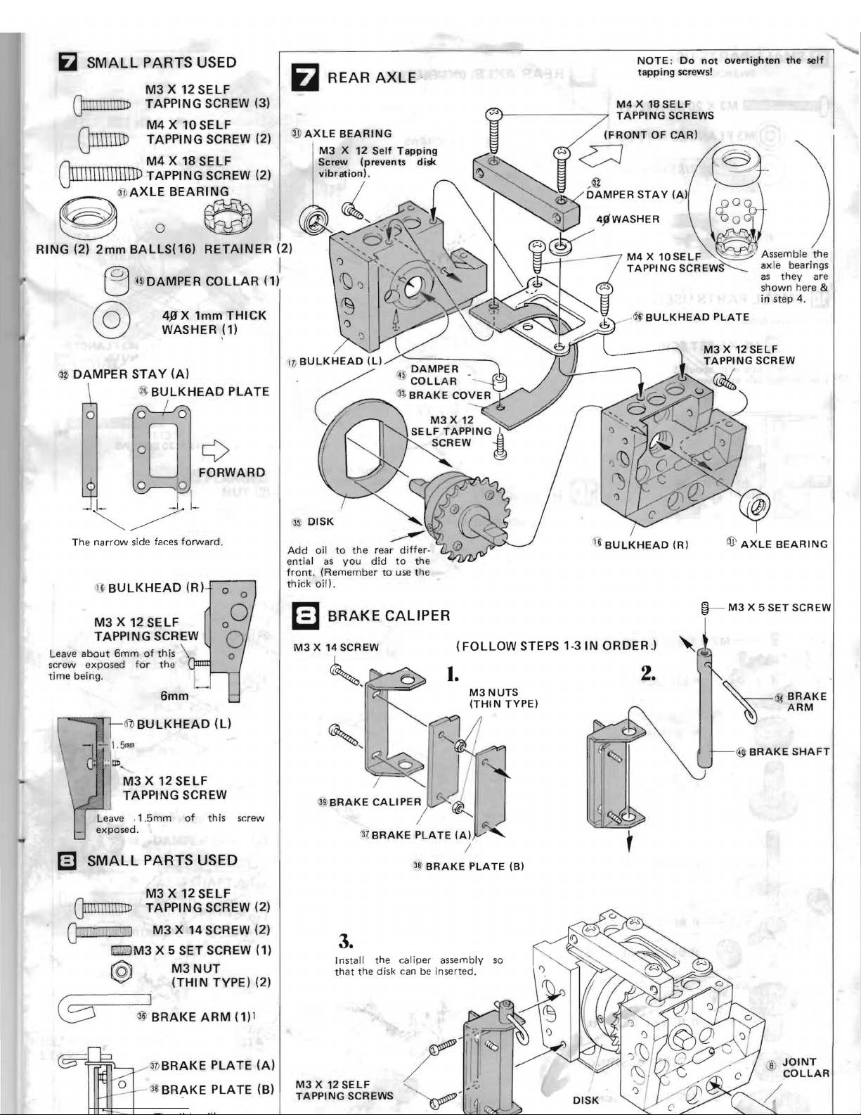
SMALL
PARTS USED
M3 X 12
SELF
G
1II
Ijl
III
Ul
TAPPING SCREW (3)
M4 X 10SELF
(}IIrrmD
TAPPING SCREW (2)
M4X
18SELF
I\III\III\IIII\D
TAPPING SCREW (2)
O
~
:
3l)
AXLE
BEAR~NG
,_,
~oO
RING
(2)
2mm
BALLS(16)
RETAINER
(2)
®
AXLE
BEARING
}-----
-----
~
TAPPING
SCREWS
(FRONT
OF
CAR)
D
4P'WASHER
M4 X 10
SE
LF
'--0-'
Assemble
the
TAPPING
SCREW~
axle
as
they
shown here &
in
step 4.
I
'3j;
DISK
~
Add
oil
to
the
rear
differ-
ential
as
did
to
the
<2~
~
BULKHEAD
PLATE
tj
~
BULKHEAD
(R)
@
AXLE
BEARING
@
o
'4~
DAMPER
COLLAR
(1)
@
4,9
X 1mm
THICK
WASHER (1)
~il
DAMPER
STAY
(A)
~
BULKHEAD
PLATE
o 0
°0
FORWARD
Th e na
rrow
side faces
forward.
u:
BULKHEAD
(R)
1-
M3
X 12 SELF
TAPPING SCREW
Leave
about
6mm
of
this
\
screw exposed
for
the
time
being.
6mm
Q1)
BULKHEAD
(U
M3
X 12 SELF
TAPPING SCREW
m
SMALL
PARTS USED
M3 X 12
SELF
sc
rew
GII
IIIIIII
l'tD
TAPPING SCREW (2)
Q
UI
I"
nli
ll
1"
Di~
,
II
M3
X 14
SCR
EW
(2)
n:'.i3
M3
X 5 SET SCREW (1)
@
M3NUT
(THIN
TYPE) (2)
J
:3jJ
BRAKE
ARM
(1) 1
C§=~'3
1>
BRAKE
PLATE
(A)
I
l~3~
BRAKE
PLATE (B)
~
REAR
AXLE
·
you
front. (Remember
to use the
thick
oil).
1=1
BRAKE
CALIPER
M3 X 14SCREW
"
'
~
I.
M3NUTS
(THIN
TYPE)
NOTE : Do
not
overtighten
the
self
tapping
screws!
M4
X 18
SELF
bearings
are
(FOLLOW
STEPS 1-31N ORDER.)
2.
3~
'
BRAKE
PLATE
(B)
3.
Install the
M3
X 12
SELF
TAPPING
SCREWS
caliper assembly
so
th
at
the
disk can be inserted.
'8'
''''''
DISK
!}---
M3
X 5
SET
SCREW
,1
~
Q.l
BRAKE
'
~
ARM
@
BRAKE
SHAFT
JOINT
COLLAR
~
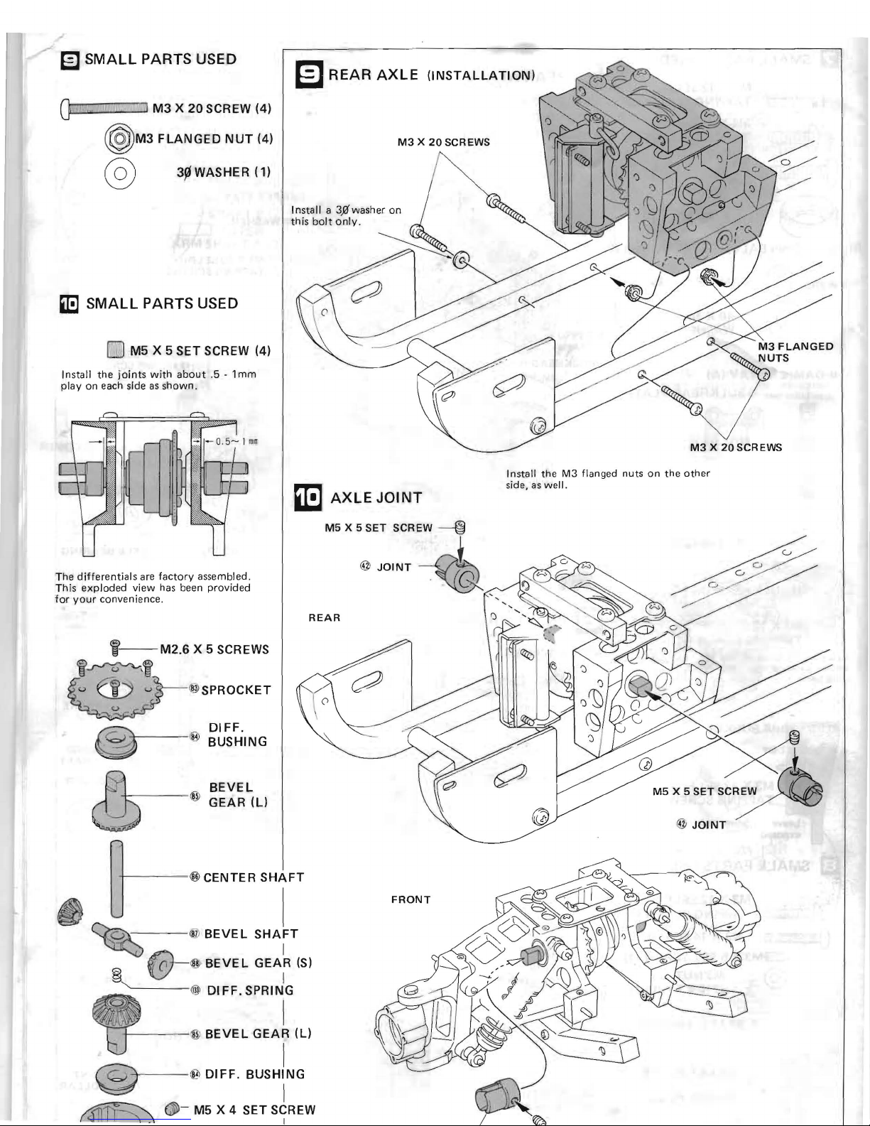
SMALL
PARTS USED
O
!l!lIl!Ii".'
!!I"iU!iIi~lij
U!lI!
i!l!mm'
l!n
M3
X 20 SCREW (4)
~
M3
FLANGED
NUT
(4)
@
3~WASHER
(1)
IE
SMALL
PARTS USED
rnlIl
M5 X 5 SET SCREW (4)
Install
the
joints
with
about
.5 - 1
mm
play
on
each
side as
shown.
II:l
I
AXLE
JOINT
The
differentials
are
factory
assembled.
Th
is
exploded
view has
been
provided
for
your
convenience.
i--
M2.6 X 5
SCR
EWS
ij>~,ij'
~"
SPROCKET
~
.
DIFF.
&
~
~
BUSHING
JSl--
:w
y~
(!J
BEVEL
M5X5SETSC~
~
@
GEAR(U
@
JOINT
REAR
~
~@CENTERSHr
~-
I)
] BEVE L
SHAFT
~@-
I
(i
i[~
BEVE L GEAR
(S)
~
I
"
@l
DI
FF. SPRING
l
6J
I
;@;
BEVEL
GEAj
(L)
®--iEl
DIFF.
BUSHI1NG
~
~
-
M5 X 4 SET
S~REW
~
REAR
AXLE
(INSTALLATION)
M3 X 20
SCREWS
I nstall a
3%
washer
on
this bol t
only.
M3 X 20SCREWS
Install
the
M3
flanged
nuts
on
the
other
side, as well.
 Loading...