

Kyosho USA-1 Nitro Crusher User Manual
RADIO
CONTROLLED
.21ENGINE
POWERED
OFF-ROAD
RECREATION
VEHICLE
CAR
CRUSHER
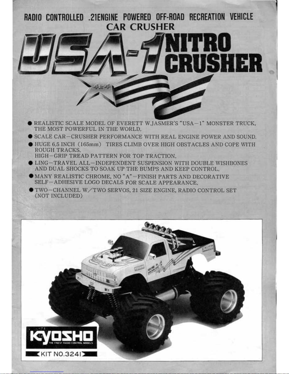
e REALISTIC
SCALE
MODEL
OF
EVERETT
W.JASMER'S
·usA
- I" MONSTER TRUCK,
THE
MOST
POWERFUL
IN
THE
WORLD.
e SCALE CAR - CRUSHER PERFORMANCE
WITH
REAL
ENGINE POWER AND SOUND.
e HUGE 6.5 INCH (165mm)
TIRES
CLIMB OVER HIGH OBSTACLES AND COPE WITH
ROUGH
TRACKS.
HIGH
~
GRIP
TREAD
PATTERN
FOR
TOP
TRACTION.
e LING-
TRAVEL
ALL-INDEPENDENT
SUSPENSION WITIT DOUBLE WISHBONES
AND
DUAL
SHOCKS
TO
SOAK
UP
THE
BUMPS AND
KEEP
CONTROL.
e MANY REALISTIC CHROME,
NO
"A"
- FINISH
PARTS
AND DECORATIVE
SELF
- ADHESIVE LOGO DECALS FOR
SCALE
APPEARANCE.
e
TWO-CIIANNEL
W/
TWO
SERVOS, 21 SIZE
E~GINE,
RADIO CONTROL
SET
(N
OT
INCLUDED)
~
KIT
N0.3241
~
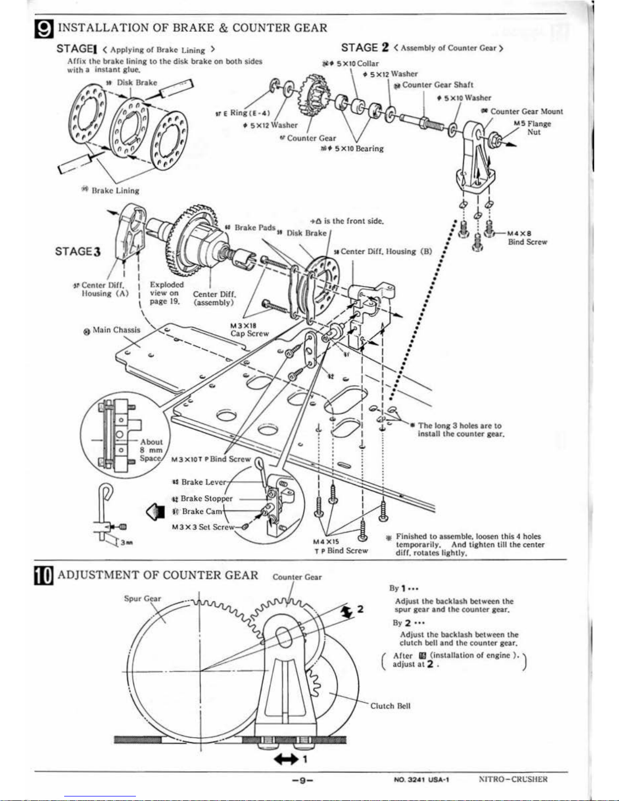
m I
NSTALLAT
ION
OF
BRAKE
& COUNTER GEAR
ST A
GE
l < Applying
of
Drake Lining >
STAGE 2 < As5embly of Counter
Cear
>
•
~
llrakc Lining
STAGE3
l>
Cenl<r OiH. 1
Housing
(A)
1
\
"f SXtOCollar
•
lit
Counter
Cear
Shaft
trERing
(£•4)
o 5 X
12
IVIISh•er
~
Coun
lcr
Gear
•
Counter
Gear
Mount
MS
Flange
Nut
view on
page
19
.
Center Oiff.
(
a...,mbly
)
~
~
Br
ake
Stc>ppcr
<?J
·
ft.
·
Dr
ake
Carnr--~r;v:
M 3 X 3
Set
Scr•riw-4'
.Of s x
10
Bearing
•
•
•
•
•
•
•
"
Center
Diff. Housing
(B)
•
);'?,!
~
:
•
•
•
•
•
•
•
•
•
•
•
•
•
•
•
•
•
•
•
•
•
•
I :
""-...
:
...........
~==.t,.,
I' :
........................
I :
.............
'-1..--"
<.;;>,
:..~
b~
~&-
r-M4
X8
,o.
Bind Screw
\':l'l
"'
I
"'~
J.
OJ
4o
" • Th< long 3 holes ar<
to
• I : lnstall the counter
gen.
.
d.
l
.
.
~:
~
,.
Finished to assemble. loosen this 4 holes
temporarily. And tighten till the center
diH.
rotates
lightly,
iin
ADJUSTMENT
OF
COUNTER
GEAR
Counter
em
By
1
...
I
•
- 9 -
Adjust
the
backlash bot ween
the
spur gear and
lhc
counter gear.
By
2 .
..
Adjust the backlash bot ween the
clutch bell and the counter gear.
(
After
ILl
(installotion of
engine).)
adjust
at
2 .
Clutch
Bell
1\ITRO-CRt:SHE
.R
l
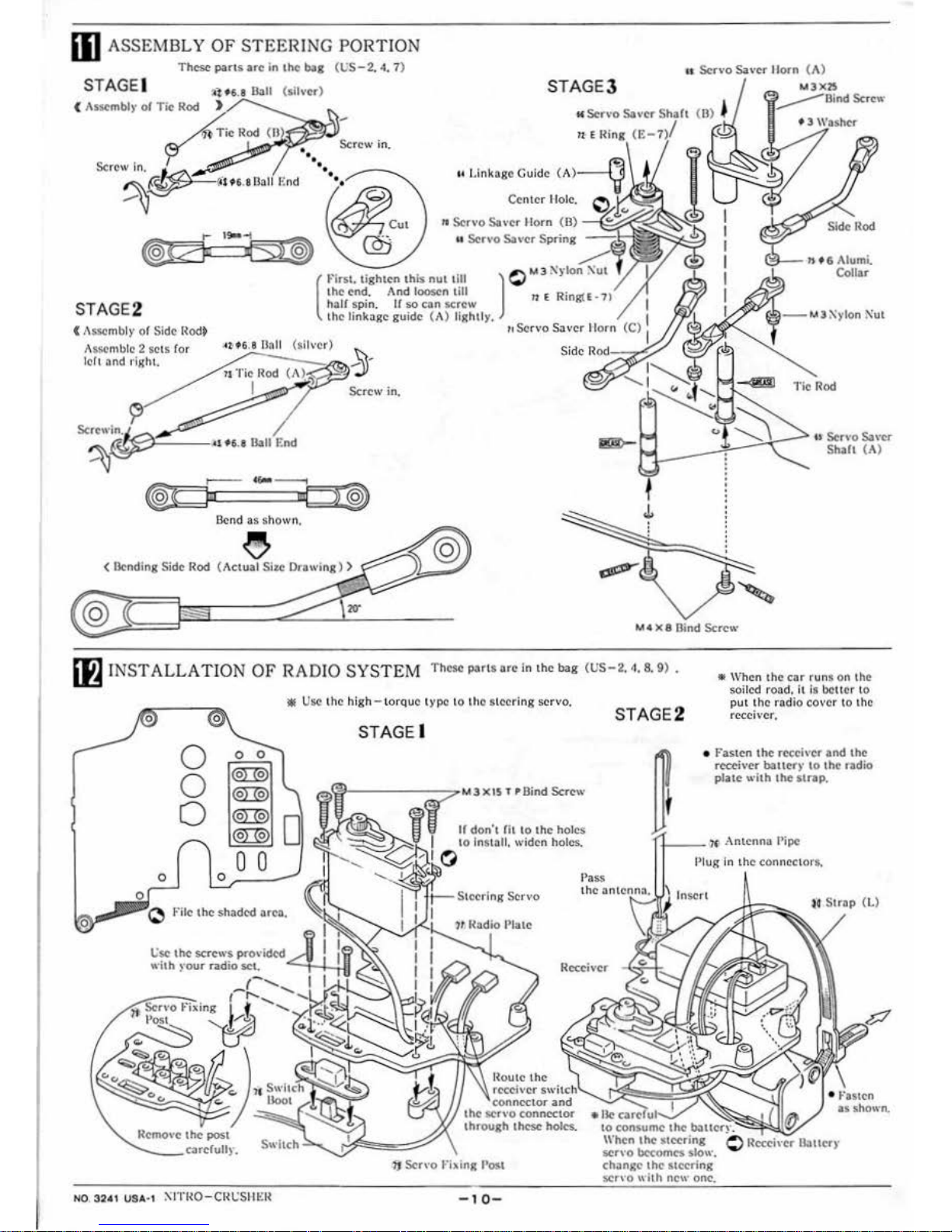
ill
ASSEMBLY
OF
STEERI
NG
PORTION
These
parts
arc
in lh< bog
(t:S-2.
4.
7)
STAGE I
(
t\sscmblr
or
Tic
Rod
STAGE2
Assemble 2
Sets
(or
l
ch
and l'lg ht.
~l06.a
&II
(silver)
)
~
Screwir;;
~
~
~~
·••
u
&II
End
ceo-
Bend as
sho
wn.
< ll<nding Side
llod
@
-
Screw in.
(fl
INS
TALLATION
OF
RADIO SYSTEM
u
Servo
Sa
,.cr
Uorn
(
t\)
STAGE3
M
3XIS
~Bind
Sere•<
11
E
Ri
ng
(t:-
{\i!l--
n t 6 Alumi.
Collar
Tie
Rod
@
M4 x 8 Rind
Screw
Th
ese
parts
are
in l ho
ba
g
(US-
2. 4. 8.
9)
.
• Use the
high
- to
rqu
e t ype to the steer
ing servo
,
STAGE2
• When the
car
runs on the
soiled
road.
II
Is bcu cr 10
put the
rad
io cover to the
rec
eiv
er.
Remove the
post
..._
_ _ carcfull)'.
NO.
3241
USA·I
1-:ITilO-Cilt.:SIIIm
If
don't Cilto
the: hol
es
• Fast
en
the rccch·cr
and
the
recch·cr
bauer)' to
the radio
plate
wilh
the
strap.
i---
?f
; Antenna Pipe
Pl
ug
in the connect
ors
.
Insert
14 Strap
(L)
Receiver
receiver swilcll'-..
connector
and
the
SCt\'O
conncc.tor
lhrough
lhcsc
boles.
wll<
<>r•cfu ii....C/
- 1
0-
10
consume
lhc
batllcr·):
_-
When
the
steering
scn
·o
becomes
sfo,,·.
chanJ,:c
the
steering
~r\'O
\\
hh
new
one.
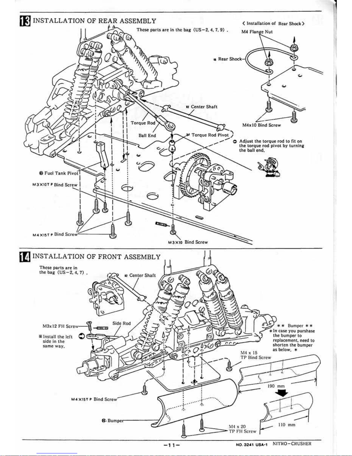
II]
INSTALLATION OF REAR ASSEMBLY
~
,
These
parts
are
in
the
bag
(US-2.
4.
7.
9)
.
< Installation of
Rea
r Shock )
M4
Flan e
Nut
()
fuel
Tank
Pivot I
M3XtOTPBindScrew
I . :
--~~·
.
I
I
I
4-
: ...
•
•
;
E:P
.
.
•
I N I
~
b&
!
~
M4 X
1ST
• Bind
Screw~
Ball End
iE
INSTA LLATION
OF
FRONT ASSEMBLY
Th
ese
parts
are
In
the
bag
(US- 2. 4.
7)
•
M3x12
HI
Screw
-
-Gall
* Install
the left
0
~~~~;/;;,_.~s_,
~SJ~!r-
sidc in the
s11me
way.
• Rear
Shock-
M4x 10 Bind
Screw
.....
u To
rq
ue
Rod Pivot)
.,.,,.,. 0 Adjust the torque rod
to
fit
on
..,....,.....
the torque rod
pivot
by
turnin&
the
ball end.
M4 X 15
.
. . ..
..
.
.
.
~-· ~
..
• • • • 0 •
* *
Bumper
**
*
Jn
case
you
purshase
the bumper
to
rep
lacement.
need
to
shorten the bumper
as
be
low. *
•
~
.,
·· .
..
..
.
--
. . . . .
.-:-.
.
••.•• '!'
.-:.
1
1
~·-
:::::::=--
M4 X 20
b-
.;
> TP FH Screw
110
mm
- 1
1-
NO.
32.,
USA· I .
1\ITilO-CilUSiiEil
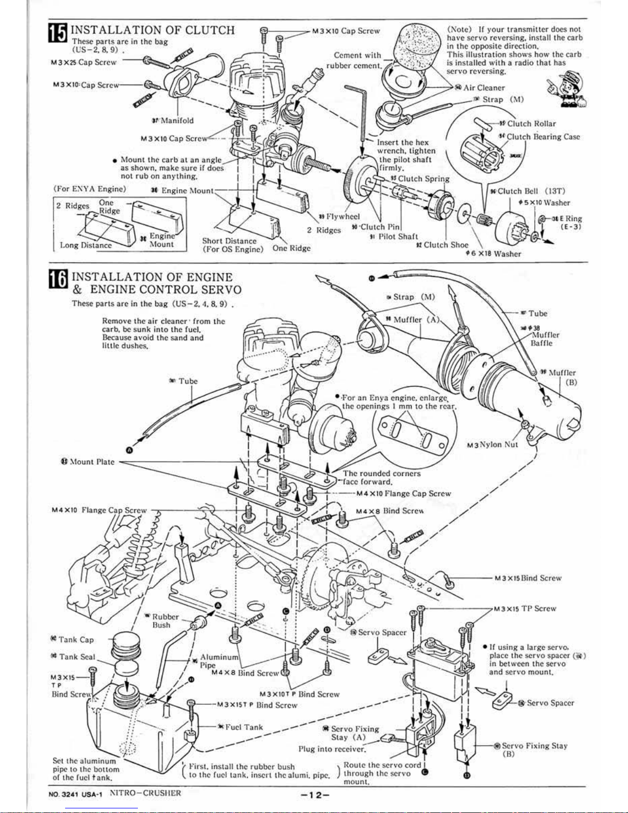
m INSTALLATION
OF
CLUTCH
li!J
These
pans ar
e in
the bag
(VS
-2.
8.
9)
M3X2SCa
pScrcw
-~
Ff--;;;;:::;:::7"
M 3
XIO
Cap
Screw
{N'ote) rr
you
r transmi
tter
docs not
h
a\'e ser
vo
reve-rs
ing. install the
carb
in the opposite
direction.
This illustr
ation shows how the
earb
is installed
with a radio
that
has
$Cr
vo reversing.
'/J--
-7~
Ai
r Cleaner
• Mo
unt
the
carb
at a n
a
n~le
as shown, make sure
not rub on
an)• thing.
(For
ENY
A Engine) 'Itt Engine
1\
, 'l
Ouln<:-
-1-
-H
2
2
Ridges
'-
1
nsert
the
hex
wrench. tighten
ft'>-..
the
shaft
'"
Strap
(M)
~-t~ Citotch
l{oiJa
r
P'"'~,h
Bearing Case
( 13T)
Washer
Short Distan
ce
(
F'or
OS Engine) One Ridge
C
lut
ch
Shoe
il!1
INSTALLATIO N
OF
ENGINE
1D
& ENGINE CONTROL SERVO
These
part
s
arc
in
lhe
b
ag
(US- 2. 4. 8.
9)
.
Remove
the
air
cleaner
· from t
he
carb, be s
unk
into t
he fuel.
Because
avo
id
the sand
and
little dushcs.
""
Tube
M4
XIO
Flange
"'
Tank Seal
M3X
I!;
--IJ
TP
Bind
Scrcc\\t
Set the aluminum
pipe to the bot tom
or t
he
Cuc
l
tan
k.
'(
First,
install
the
rubbe
r bush
tO
the
fuel
tJnk.
insert the a
lum
i.
pipe,
N0
.3241
USA·1 1\ITRO-CilUSI-IER
-12-
..
Strap
(i\1)
)
l~outc
the servo
through the servo
mount.
H
XIS
Washer
• I( using a la
rge
servo.
place the
servo
spacer (.W)
In bet ween t
he
set
\'O
and servo mount.
~
I
1
1
~*"
Servo
Spacer
i-i
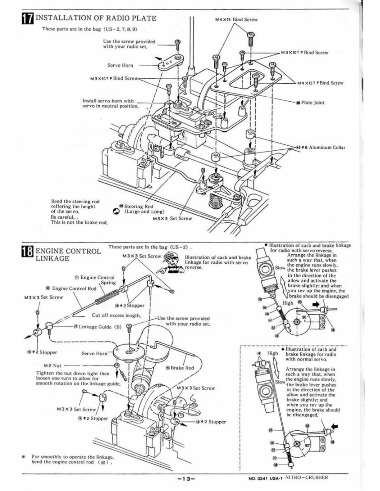
[fj
INSTALLATION
OF
RADIO
PLATE
Th<Se
ports
are
in
the
bag (t,;S
- 2. 7,
S.
9)
flcnd the
steering
rod
reUeting the
height
of
the
servo,
lle
carefu
l ....
esc
the
screw
provided
with
)'OUr
radio
set.
-
-~
Servo
I lorn
~Steering
Rod
C)
(Lar
ge
and
long
)
1'his is
not
the
brake
rod.
M
3X3
Those
port
.s ore in
the
bag
(US-2)
•
M•
x1s
Oind
Screw
Plate Joint
• Illustration
or
earb
~nd
brake
lin
kage
ii3
ENGINE
CONTROL
LINKAGE
lllus
tration
of
carb
and
brake
linkage
for
radio
with
servo
f
or
radio \\'ith
servo
rev~
Arrange
the linka.
ge
In
such a way
that.
when
che
engine
run
s slowly.
M3 X 3
Se
t Screw
I
(h 2 to
pper
I
Cut
off
excess
length.
I
1.--
IJ'"'
the
screw prov1dtd
..J.---...
with your
radio
stl
•
for
smoothly
to
opera
te
the
linkag
e.
bend
tho
cn~rino
control
rod
( lib ) •
-13-
Q
Slo"
the
brake lever
pushes
High
in
the
direction
or
the
allow
and activate the
brake
slightly:
and
when
you
rev up the engine. the
brake
should
be
disengaged
High •
..
• Illustrati
on
ol
carb
and
brake
linkage
lor
radio
with
normal
servo.
Arrange
the
linkage in
such a wa y
that
whtm
'f.i§~LSio":t;h~e
eng
ine runs slowly.
1
brake
le•·
er
pushes
in a he
direction
of I he
allow
and
acaivaae
the
brako slightly:
and
when
you
rev
up 1 he
engine.
the
brake
should
be disengaged.
NO. 32AI USA• I
ii:
JTK
O-CllUS
IIER
I
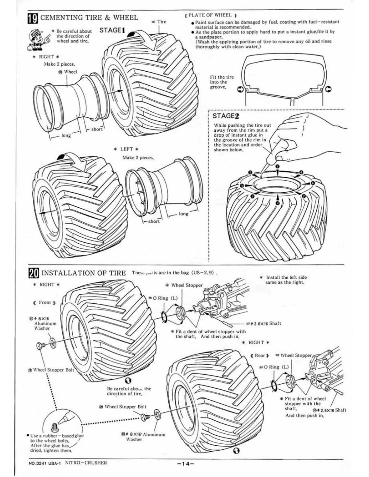
mJ
CEMENTING
TIRE & WHEEL
• · Tire
•
•
Ik
careful
about
the
dir«tion
or
wheel iind tire.
*
RI
CIIT *
Make 2 pieces.
8 Wheel
-
-short
* I.E:FT *
Make 2
pieces-.
1
I'LA
TE
OF
WHEEL )
--long
•
Paint
surface
can
be
dama~tcd
by
fuel.
coating
with
fuel- resi$tant
material
is
recommended •
• As
the
plate
portion
to
apply
hard
to
put a instant
glut":
.filr
it
by
a
sandpaper.
{Wash
the
applying
POrtion
or
tire
to
remove
any
oil
and
rinse
thoroughly
with
clean
water.)
--
Fit
the tire
into
the
groove.
. .
.........................................................
4
•••••• 0 ...................
0
••••••••••
STAGE2
While
pushing the
tire
out
away rrom th·c
rim
put
a
d
rop
of
instant
glue in
the groove
of
the
rim
in
the location
and
order
shown
below.
)
)
I
J
P1D
INSTALLA
TION OF
TIRE 1"ne
••
,.rts
areln
the
bag
<us-2.
9) •
* Install
the
left side
same
as
the
right
.
*
RIC11T
*
1i
Wheel Stopper
( Front )
8 f
8X16
t\luminun\
\\'oshcr
•
•
•
•
•
•
•
•
•
•
•
•
•
0
Be
careful
abo
.. ~ the
dirc~tion
or
tire .
~
8 Wheel Stopper
Bo
lt
~~
··· ··
· ·
·······
·
······
~~
• t:sc a
rubbcr-b3.scdg1u!
8f
8X16'Aiuminum
to
the- wheel bolts. I Washer
.I
her
the
Rlue
has/
dried, tighten them.
•
J:Oit
3 dent or wheel st
opper
with
the
sha
rt. And then push in.
* I!ICIIT *
-14
-
•
Fit
a dena
or
wheel
stopper
with
the
sha
rt.
®f 2.6X 16 Shart
.~nd
then
push ln.
<
Bac
k >
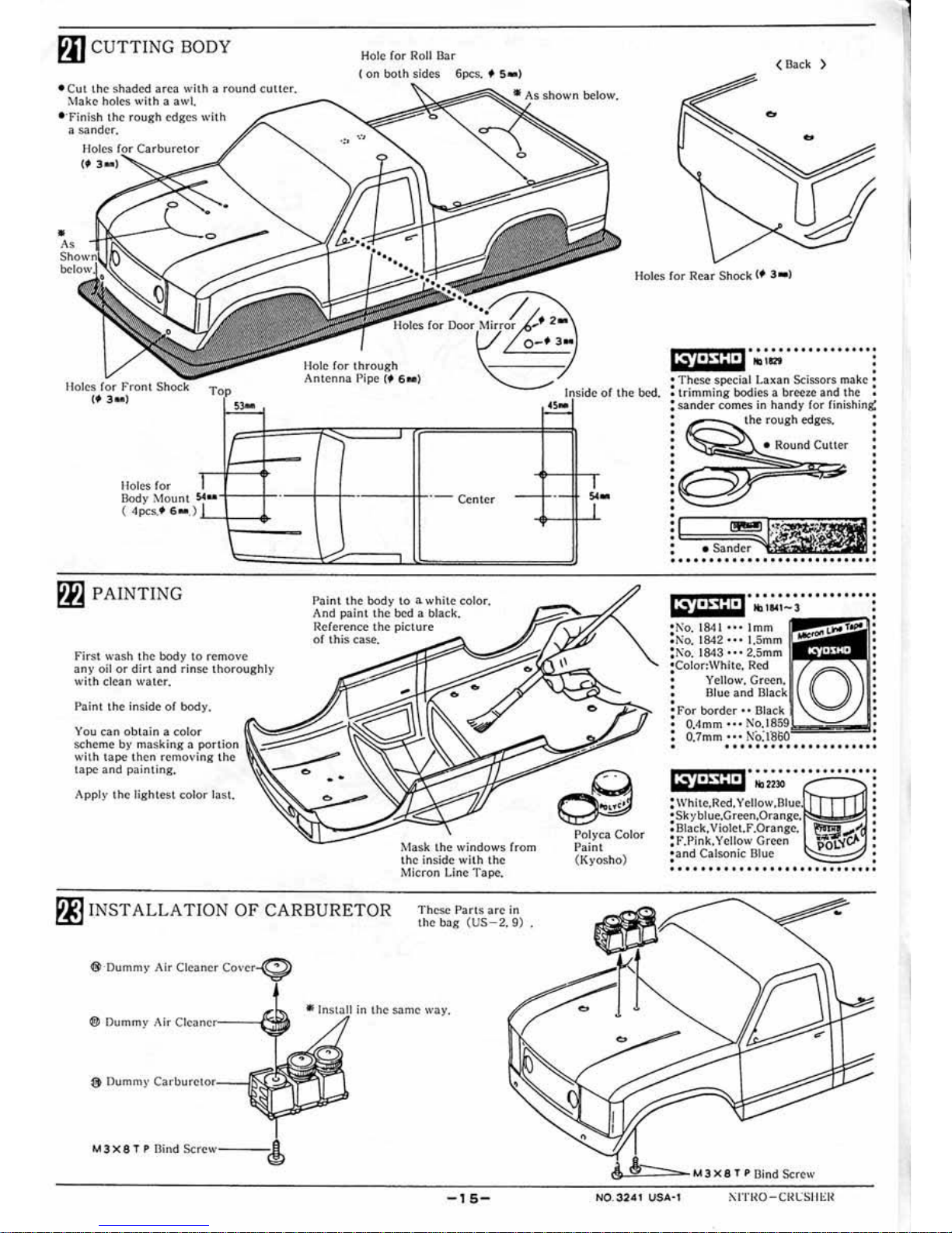
PIJ
CUTTING
BODY
Hole for Ro
ll
Bar
(on
both
sides
6pcs. f S• )
• Cut the shaded
area
with a round
cuucr.
Make
holes
wiih
a awl.
____
........_
• ·rinish
the
rough
edges with
a
sander.
«:~t
Holes f
or
f'ront Shock
(
.3M
)
Top
~-
Ho
le for throug
h
.
Antenna
Pipe c•
6•)
Holes
for
Oody Mount
~ u+--t-
--
+-
1--
--
--+!-·-
Center
( 4pcs.• 6
..
.)
..._
1=~
~-
P}iJ
PAINTI
NG
First wash
the
body
to
remove
any
oil
or dirt and rinse
thoro
ughl
y
with clean
water.
Pai
nt
the inside
of
body.
You c.an o
bta
in a color
sc
heme
by maski
ng a portion
wilh
tape
then removin
g t
he
tape and painting,
App
ly
the
lightest color las
t.
Paint
the body
to
a w
hite
colo
r.
And
pain t t
he
bed a b
lac
k.
Reference t
he pic
ture
of
thi
s ca
se.
!\
•1ask t
he
windows
(r
om
th
e inside
wilh the
Micron Li
ne
Tape.
~
INSTALLATION
OF
CARBURETOR
Th
ese
Parts
are
in
Lhe
bag
(US - 2.
9)
<l!i>·Dummr
Air Cleaner
Cove,r-(!
~~
0 Du mmy
Air
Clc
;;~ner----t"
in
lhc
same
way
.
-
15-
Holes f
or
Rear Shock (f 3- >
Inside
of
the bed.
•s•
~-
Pol
yca
Color
l">a
int
(Kyosho)
••••••••••••••••••
ICYDSHD
"' 1121
•
•
•
• These
spe'Cia
l Lax
an
Scissors make •
: trimming bodies a breeze and the !
:
sander
comes in
handy
for rinish i
nS:
:
the
rough
edges
, :
•
•
•
•
•
•
•
•
•
•
•
•
•
•
•
•
•
•
•
•
•
~=~l
•
•
•
•
•
•
•
•
• • • • • • • • • • • • • • • • • • • • • • • • • • • •
••••
•• • • ••••••••••
ICYDSHD
•N'o 1
841 •••
l mm
• •
. No. 1
842
• • • 1.5mm
!
Ko.
1848 • • • 2
.5m
m
•
Color:White,
Red
•
•
Yello
w,
Green.
:
Blu
e
and
""oc"·l
•
•
For
border
•• .,,.,
.,
! O,tlmm •• • No.
:
0.7mm
••• NO.
•
•
•
•
•
•
•
ecyoSHD
•
•••••••••••••••••
•
..,
2230
•
•
•
•
•
•
•
: Black. Vio
let.f.
Orangc.
•
•
;
f.Pink.
Yellow Gr
een
•
•
•and C
al
son
ic
Blue
•
•
•
• • •
• • • • • • • • • • • • • • • • • • • • • • • • •
~
'==-===---
M 3 X 8 T P
Dind
Screw
N0.3241 USA·1
!\ITRO-CRt:SI!Eil
I
 Loading...