

Kyosho USA-1 Monster Truck User Manual
/"'
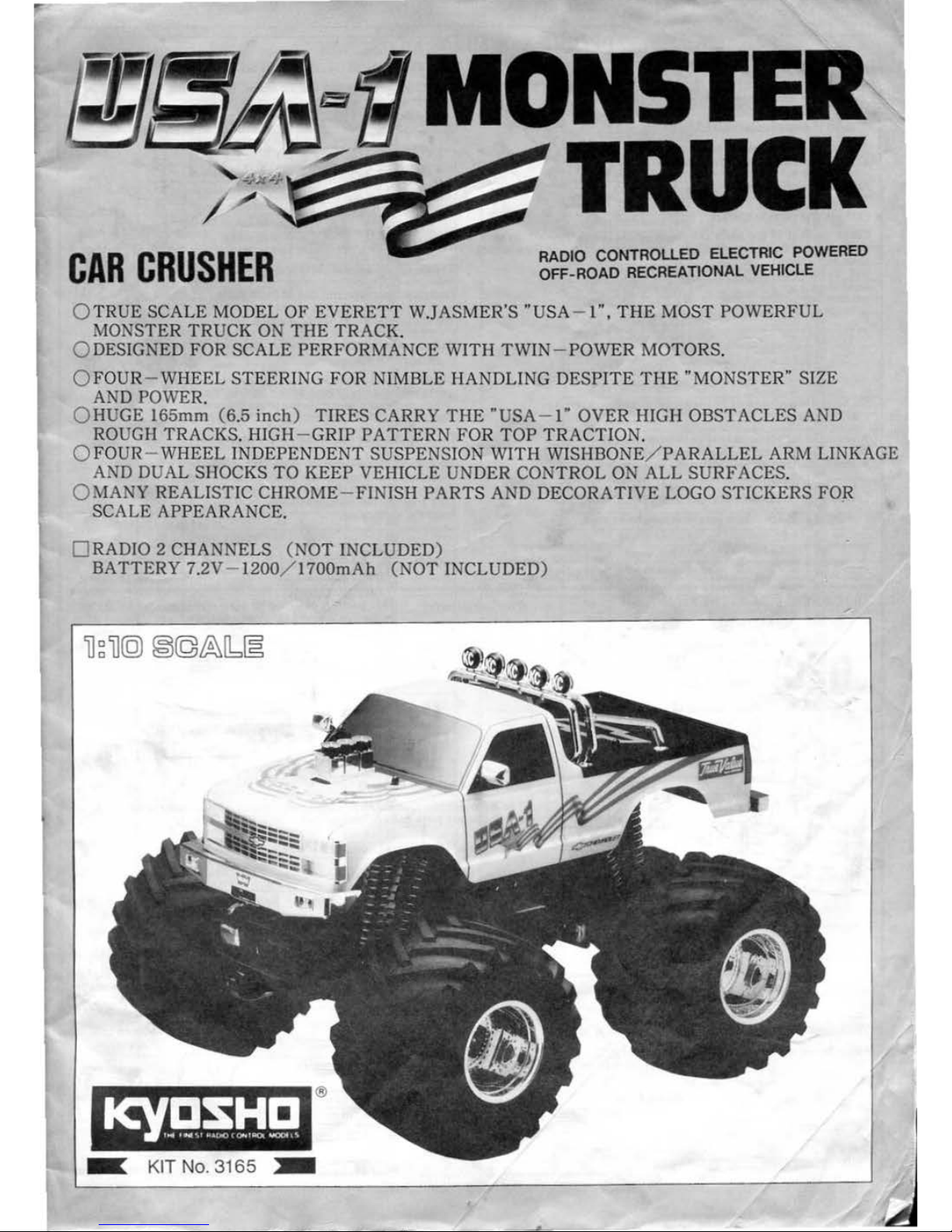
CAR
CRUSHER
RADIO
CONTROUED
ELECTRIC POWERED
OFF- ROAD RECREATIONAL VEHICLE
Q
TRUE
SCALE
MODEL
OF
EVERETT
W.JASMER'S
"USA
- 1
", THE
MOST
POWERFUL
MONSTER
TRUCK
ON
THE
TRAC
K.
Q DESIGNED
FOR
SCA
LE PER
FORMANCE
WITH TWIN
- POWER MOTORS.
0 FOUR- WHEEL
STEER
ING
FOR
NIMBLE HANDLING
DESPITE
THE
"MONSTER"
SIZE
AND
POWER.
Q HUGE
l65mm
(6.5
inch) TIRES
CARRY
THE
"USA-1"
OVER HIGH OBSTACLES AND
ROUGH TRACKS. HIGH- GRIP
PATTERN
FOR
TOP TRACTION.
Q FOUR- WHEEL INDEPENDENT SUSPENSION
WITH
WISHBONE/
PARALLEL
ARM LINKAGE
AND
DU
AL
SHOCKS
TO
KEEP
VEHICLE UNDER
CONTROL
ON
ALL
SURF
ACES.
Q MANY REALISTIC
CHROME-FINISH
PARTS
AND DECORATIVE LOGO
STICKERS
FOR
SCALE APPEARANCE.
0 RADIO 2 CHANNELS (
NOT
INCLUDED)
BATTERY
7.2V - 1200/
1700mAh
(NOT
INCLUDED)
®
Ill[
KIT N
o. 3165
:1111
r
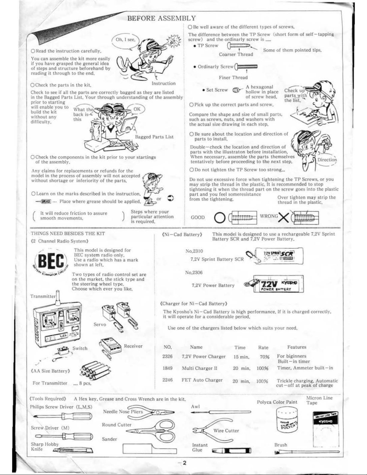
BEFORE
ASSEMBLY
ORead
the
instruction
carcfull)•.
You
can
assemble the
kit
more easily
if
you
have
grasped
the
general idea
or
steps
and
structure
beforehand by
reading it
through
to
the
end.
OCheck
the
parts
in
the
kit.
Instruct
ion
Check
to
see
if all
the
parts
are
correctly
bagged
as
they
are
listed
0
Be
well
aware
of
the
diHerent
types
or
screws.
The
difference between
the
TP
Screw (
short
form
of
self-tapping
screw)
and
the
ordinnrly
screw
is
.....
•
TP
Screw
ail!!!'!!:
ID
I Some
of
them pointed tips.
Coarser
Thread
• Ordinnrly
ScrewQ
'
Finer
Thread
=-..-
A hexagonal
•
Set
Screw
~
hollow in place
in the
Bagged
Parts
List. Your
through
understanding
of
the
assembly
of
screw
head.
prior to
starting
will
enable you
to
build the
kit
without
am·
difficulty. •
OCheck
the
components in
the
kit
prior
to )'Our
startlngs
or
the assembly.
Any
claims for replacements
or
refunds for
the
model in the process
of
assembly will
not
accepted
without
shortage
or
in!criorit)'
or
the
pans.
0 Learn on the
marks
described in
the
instruction.
-g)
... Place
where
grease
should be applied.
c=
=-
0 Pick
up
the
correct
parts
and
screw.
Compare
the
shape
and
size
of
small
parts.
such
as
screws. nuts.
and
washers
with
the
actual
size
drawing
in
each
step
.
0
Be
sure
about
the
location
and
direction
or
parts
to
install.
Double-check
the
location
and
direction
or
?;
parts
with
the
illustraton
before installation.
When necessary. assemble
the
parts
themselves
tentatively before proceeding to
the
next
step.
0
no
not tighten
the
TP
Screw too
strong
...
'
Direction
. '
--
Do
not
usc excessive force
when
tightening
the
TP
Screws.
or
you
may
strip
the
thread
in
the
plastic. It is recommended to
stop
tightening
it
when
the
thread
part
on
the
screw
goc.
into
the
plastic
part
and
you reel someresista nee . .
from
the
tightening Q,•cr tighten may
stnp
the
·
thread
in
the
plastic.
(
It
will redu
ce
friction to
assure
smooth
movements.
)
Steps
where
your
particular
attention
is required.
GOOD
TIIINGS NEED BESIDES T ilE KIT
(2
Channel Radio System)
Transrniuer
(:\A
Size
Battery)
This model
is
designed for
BEC
syste
m radio only.
Usc a radio which
has a mark
shown
at
left.
Two
types
of
radio
control
set
arc
on
the
market.
the
stick type
and
the
steering wheel type,
Choose which ever you like.
Servo
f'or
Trans
mitter
.... 8 pes.
(1-11
-Cad
Battery)
This
model is designed to usc a rechargeable
7.2V
Sprint
Battery
SCR
and
7.2V Power
Battery.
1'\o.2310
7.2V Sprint
Battery
SCR
l':o.2306
7.2V Power
Battery
(Charger
lor
NI-Cad
Ballcry)
The
Kyosho's
l'i-Cad
Dauer)'
is high performance. If it is
charged
correctly.
it will
operate
for a considerable period.
Usc
one
of
the
chargers
listed below which
suits
your
need.
NO.
Name
2326 7.
2V
Power
Charger
1849 Multi
Charger
II
2246
f'ET Auto
Charger
0
·--·-·
Time
15
min.
l~ate
Features
7096
For
biginncrs
Built-
in
timer
20 min.
10096
Timer. Ammeter
built-
in
20 min.
10096
Trickle charging. Automatic
cut
-orr
at
peak
of
charge
(Tools Required) A Hex kC)', Grease
and
Cross Wrench
are
in
the
kit.
Polyca Color Paint
:0.1icron
Line
Tape
Philips Screw Driver (L.M.S) Awl
--<====
==
• • 0
..
•
.....
cr:
!
D
Screw Driver
(M)
C=t
§
J
D
Sander
Sharp
llobb}
Knife
Brush
Instant
Glue
lii
lliC:[I
JMC=::JIIJ
I
- 2
JIJg
:>:o.
IKe}·
::
I
2
3
Ulister
4
5
6
66
001<-1
9
10
11
12
13
14
15
USI<-2
16
17
18
19
zo
Zl
22
OOA-3
23
USI<-4
24
USI<-5
25
26
27
28
29
001<-7
30
31
32
33
34
US
A-8
35
36
37
38
39
40
41
US
A-9
42
43
(4
45
46
47
48
49
USA-10
so
I
51
52
53
54
55
56
57
58
59
USA-II
60
61
62
63
64
65
67
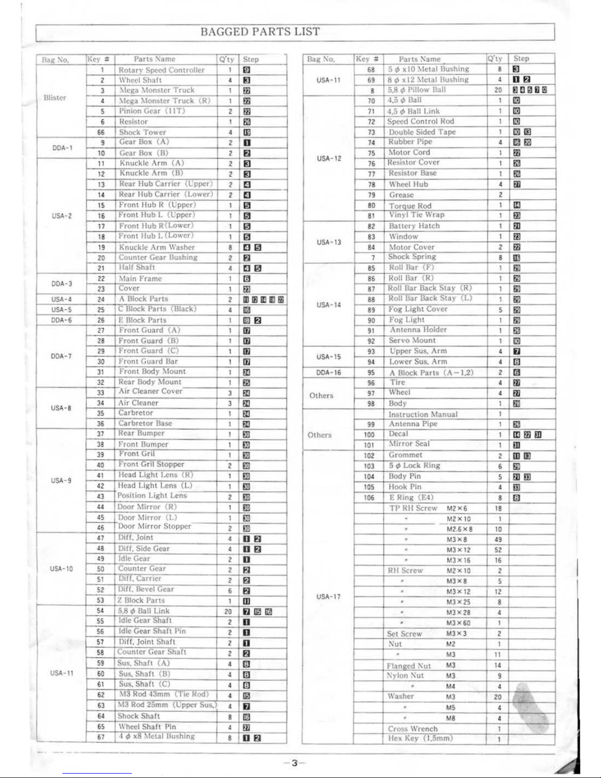
BAGGED PARTS
LIST
"
I
Q'ty
l~o1ary
Controller
I
'""""
4
'ter 1 ruck
I
\leg a :\lon,ter
Truck
( R)
I
1
Gear
(liT)
2
l~esistor
I
Shock
Tower
4
Dox
(A)
2
Box
((ll
2
Kn·~~
~
~Arm (A)
2
" '
, 1
\rm
(B)
2
Rear
Hub
lL
2
1
"~"'
llub ""'
""
C
.,
z
,.,
um
Hub
I! (Upper
)
I
1
rrun!
Hub L
n·
. '
1
1
rronl
Hub R I
1 r
ront
llub
I.
' I
1
!K
Arm
8
Gear
II
2
•
JlalfShaft
4
\lain
Frame
I
1
:\
Par,.
2
c
"'i3i'OC'k
Pa r 1 s
(i3fiiCi()
4
E
131ock
Parts
1
rrum
r:
(M
1
II
Gp>r<l
~
I
Front
Guard
(C)
1
I
front
Guard_I3(Jr
I
r
rom
Body :'-fount
I
•.u• .,
\f
ount
I
Air
Cleaner
Co,•er
3
AirO.
3
""'
uo
~•v• I
Ba,;c
I
llear
Bu
.•
1
Front
1
r
rom
vrll
1
rrunt
Gril
2
I lead Light
-(I<)
I
I I
iuh1
l."ns
{L)
I
Position
Light
Lens
2
Door
:\lirror
1 R)
I
1\
•
•v
t)
1
,
·hrror
topper
2
I Dilf.
4
Dill. Side
Gear
4
Idle
Gear
2
Counter
v•u•
2
Oil!.
Carrier
2
Dill. .1
vear
6
Z
131ock
Parts
I
8¢
Ball Link
20
lfe
v~o
;:)IIUil
2
Idle v_
-·
'"'""
Pin
2
0111.
Joint
Shall
2
vw.'
Shall
2
Sus.
Shaft~
4
Sus.
Shaft
(ll)
4
_Sus.
Shalt
{Cl
4
:\13
Rod~
\
lie
KOO_J_
4
I \13 Rod
·Sus
4
'
Shaft
8
Wheel
Shall
Pin 4
I
~XI!
..
.,
8
ji]
_
i
~
~
1l_
L
[b
b
-
~
j
j
!
~
!
l
~
1m
=I
~
i
j
~
J
D~
Bag
\o.
USI<-11
USA-12
USI<-13
USI\·14
USA-IS
I Key
::
Pans
:'\a me
68
5 ¢ x 10
\lrtnl
69
8
~
x
12
Metal Bushing
8
5.11
l
13;111
70
4.5 1
13all
71
4.5 ¢ Ball Link
72
Con 1 rol Hod
73
~
74
R
75
76
77
·Pipe
1
4
I
1
1
78
\\
nee•
Hub
4
2
f.!!!-
'-----1
79
Grease
89
~·og
l.ight
-v
· 5
90
Fog
•ht 1
91
i\1 1
92
..Cr•v
. I
93 Sus.
Arm
4
4
i
--
--i
94
Lower Sus.
Arm
~;O~
OA~-~16~~~9~5~A=~~
Parts
(A-1.2)
Z
~
:~~-rrn:~
:
Others
98
Body I
·~•;,.,
l\lanual
I
99
Antenna
npc
I @
Others
100
II 1
1
~J!!_
101
i\
irror
seal
_ill___
_
~-------t:i~o~
zcj~
~~m~e~t~=========j==
z~~~
~~:~~!=t~S~~~.t~.i~P~ikntR~in~g========t=~:=t
iil
~
~
~--~
~
1
OS
: Pin 4
8
Lm_
:------1
106
_E Ring
(E4)
IQ
TP
RH
Screw
M2
x 6
18
•
__
M~XIO
I
~--~----.-----M~2~.6~X-8
~~-
I~G~
----
---;
•
M3X8
49
•
MJX
12
52
•
MJX
16
16
Rll
M2 X 10
2
• MJX8 5
•
M3XI2
12
USA-17
MJX
25
8
•
•
M3X28 4
• M
J~
I
I
Set
!':rr~w
MJXJ
2
Nut
_!.1_2_
I
•
MJ
11
MJ
14
' :>:yton
Nut
MJ
9
M4 4 ' ,
r---~~\\'a~shc--r----~
M~J--
---i-720~~~
:--\---i
•
•
•
M8
4 ' 2
I
'\.
/
Hex
Ke~·
0.5mm)
1
3 -
•
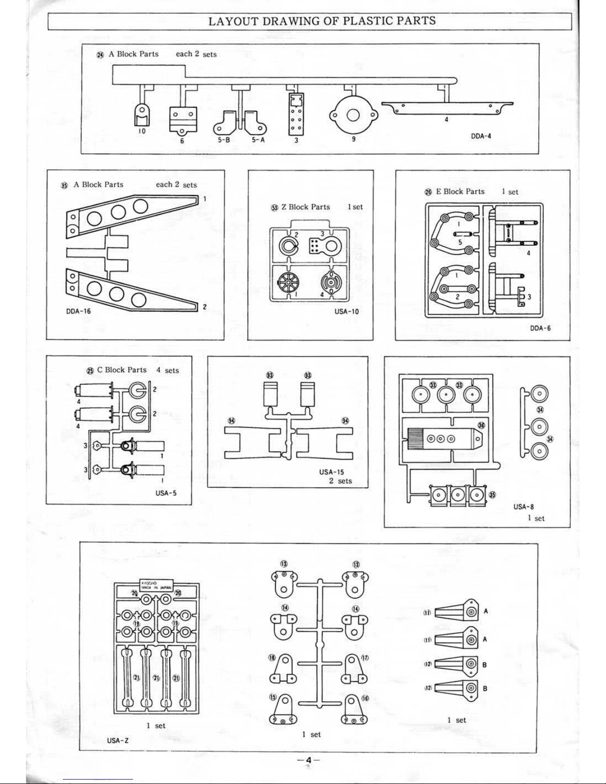
LAYOUT
DRAWING OF PLASTIC
PARTS
® A Block
Parts
each 2 sets
0 0
10
5-B
® A Block Parts each 2 sets
ooo
.JJ
0
,......
0
II
I
I
I
.....
I
I
I
~
Jl
ooo
""il
DDA
- 16
z
@ C
Block
Parts
4 sets
4
USA-5
®
I
1
se
t
USA-Z
5- A
[3
0 0
0 0
0 0
3
9
® Z
Block
Parts I set
USA-10
USA-15
2
se
ts
~
~fJ)=:'J==u;
I set
•
0
•
4
DDA-4
® E Block Parts
I
)
!!
I @7:
~
~~l
-.....:
@)c
,.
it
'
@)C
ik
® @)
®
21®lc
-......:
@
lL....i
Oh
~A
no
~
A
1
111(
~
B
~1l
~B
I
set
•
I
se
t
I
4
IP
l!:u
3
DDA-6
USA-8
I set
.__
_ _ , _
____
__
___
__
_ _
___
__
_ _
____
__
_ _
_j
- 4 -
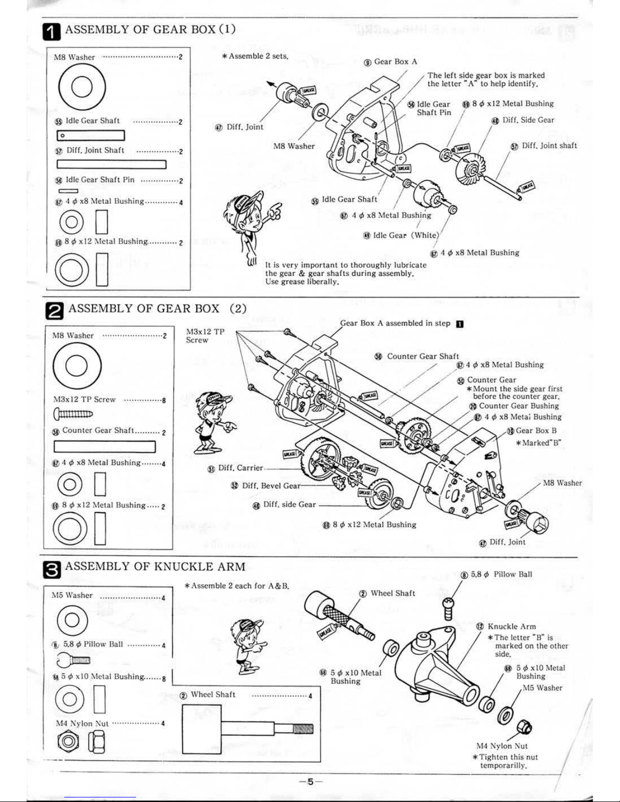
0 ASSEMBLY
OF
GEAR
BOX
(1)
M8
Washer ........ ...
...................
2
® Id le
Gea
r S
haft
··
·······
·· ·····
··2
I o
·
~
Diff
.
Joint Shaft ·················2
®
Idl
e Gear
Shaft
Pin
···············2
® tl
r/>
x8
Metal Bus
hing
.............
4
@0
@ 8
r/>
x 12
:0.1eta
I Bushing .....
.......
2
*A
ssemble 2 sets.
®Gea
r Box A
@
Di
ff.
Joint
The left side
gear box is marked
the
letter
·A·
to help
identify.
®Idle
Gear @ 8
r1>
x 12 Metal Bushing
S
haft
Pin
M8 Washer
It
is
very impor
tant
to thorough!)'
lubr
icate
the
gear
& gear s
hafts during asse
mbly.
Usc grease
liberall
y.
@ Di
ff.
Side Gear
I" o; ".
'''"'
"''"
~
ASSEMBLY
OF
GEAR
BOX
(2)
Box A a
ssem
bled in step D
M8
Washer ·······
··
··· ············2
M3
xl2
TP
Screw
® Counter Gear Shaft
.//
M3x
12
TP
Screw
··
·············8
Qt
I IIlli Ill P
®Counter
Gear Sha
ft
...
.......
2
® 4
tJ>
x8 Metal
Bushing ········4
®
Oiff. Car-r
ie•c·--
-
-\
@0
®
Diff.
Bevel
Ge;ar---~;~
@ 8
tJ>
x 12 Meta l
llushing
.....
2
00
(i] ASSEMBLY
OF
KNUCKLE
ARM
*A
ssemble 2 each for
A&
B.
l\15
Washer
••
0 • 0 0
•••••••••
• • 0 • 0 0 0 • 0 4
@
1;
5
.8
tJ>
Pillow
Ba
II
.........
....
4
O=m
1§
5
tJ>
x
10 1\letal
llushi
ng
.......
8
@ D ® Wheel Shaft
o o o o o o o o I o o o o o o o o o o o o o 4
M4
Nylon
Nut ····
···
·······
···
·· 4
@ 8
tJ>
x
12 Metal
Bushing
® Wheel
Shaft
® 5
tJ>
x
10
Metal
Bushing
4
tJ>
x8
Metal Bushing
® Co
unt
er
Gea
r
*
Mount the side gear
fir
st
before the co
unt
er gear.
Counter Gear Bushing
4
tJ>
x8 Meta; Bushing
Gear Box B
* Marked"B"
MS
Washer
@
Diff.
Joint
®
5.8
tJ>
P
ill
ow Ball
@
Kn
uckle
Arm
* The l
etter
• B" is
marked on the o
th
er
side.
® 5
r1>
x
10
Metal
Bushing
M5
Washer
@ ©
M4
Nylon
Nut
I
*
Tigh
ten
this nut
·
--
---
----------------
----
--
----------
------------
----
----
--------
------
--------
--
----~
t~e~m~po~ra
~
r~il~ly
~·
----~
- ,5 -
I

m ASSEMBLY
OF
REAR
HUB
CARRIER
*A
ssemble I set each
for
A &
13.
Tighten screws so the
knuckle
arm can move smoothly.
11
Knuckle
Arm
Washer
··
4
:.13x8
TP
RH
Screw
···
···
······
4
QUill!•
® 5.8 ¢
Pillow
Ball ·
········
·2
()mm
:\13x12TP RH
Screw·········
·4
On
11111
mo
®Half
Shah
Knuckle
Arm
(B)
assembled
in
step
l!J
.
*
Marked
• B"
on
the
other
side.
® Rear
Hub
Carrier (Lower
)
~
ASSEMBLY
OF
FRONT
HUB
CARRIER
* Assemble I
set
each
for
A &
B.
Tighten screws so the knuckle
arm can move smoot
hly.
lJ, Knuckle
Arm
Washer
..
,
M3x8
TP
RH Screw .......... 4
QIIIUI•
.-J!:1
~
M3xl2
TP
RH Screw
® 5.8 ¢
Pillow
Ball~
1:1
lf
J:')kr:
M3x8
TP
RH Screw
M3xl2
TP
RH
Screw~
ij
®
Half
Shah
V
QJ)
Knuckle
Arm
Washer
• 1 I
.1~,.
.,
®
Front
Hub
Carrier R (Upper)
~
'"""
@ (other
side)
Knuckle
Arm
A)
assembled
in
step
l!J
.
*Mark
ed
'
A·
on the
other
side.
@ Rear
Hub
Carrier
(U
pper)
I ; I
I
0\ I
® Rear
Hub
Carrier
(Lower)
L r---.._j
@
Front
Hub
Carrier R
(U
pper)
~
®Front
Hub
Carrier
R
(L
ower)
®
Front
Hub
Carrier R (Lower)
® 5.8 ¢ Pillow Ball ............ z
I
Omm
L
_j
-Pb
@ (other
side)
~
~
®
Knuckle
Arm
Washer
~
M3x8
TP
RH Screw
:\13x
12
TP
RH Screu ............. 4
01111111111
p
-
ASSEMBLY
OF
MAIN
FRAME
*I
nstall
Front
& Rear Gear Box.
M3x
16
Tl'
Rll
Screw
:\13x
16
TP
RH Screw
..........
a
()IIIIIIIIIIIIIIIP
Gear Box
assembled
in
step a
M3x8
TP
RH Screw ............
,z
~
A-2
M3 Washer
@
......•....
•.•.•.
..
4
M3
Washer
:.t3x8
TP
RH Screw
*
Temporarilly
tightened.
M3
x8
TP
RH Screw
M3xl6
TP
RH Screw
- 9-
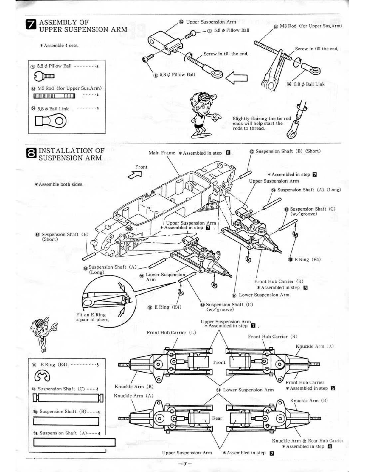
ASSEMBLY OF
UPPE
R SUSPENSION ARM
*A
ssemble 4 sets.
® 5.8 ¢ Pillow Ball · · · ·· ·· · · · · · · · · 8
Onmm
<0>
!V
I3
Rod
(ro
r U
pper
Sus.Arm)
1111111
111111111
11111111
.•....... 4
® 5.8 ¢ Ball
Link
·············
4
·"
)
Q)
@
M3
Rod
(for
Upper Sus. Arm)
Screw
in
till
the end.
ends
will help
start
the
rods
to
thread.
Screw
in
till
the
end.
® 5.8 ¢
Ba
ll
Link
~
r-1
INS
TALLATION OF
~
SUSPENSION ARM
Main
Frame * Assembled
in
step
fiJ
@ Suspension
Shah
(B)
(Short)
* Assemble
both
sides.
I}
St·spension
Shaft (B)
(S
hort
)
®Sus
pension
Shah
(Lon
g)
.:;---...
Fit
an E Ring
a
pair
or
pliers.
<g
E
Ring (E4)
···
····
···
···
····8
@1)
Front
®
Lower
Suspension
Arm
@ E
Ring
(E4)
Fr
ont Hub Carri
er
(
I.)
l
~
Suspension
Shaft
(C) ··· ··· 4
rn
10
Knuckle
Arm
(B)
Knuckle
Arm
(A)
~
Suspensio
r\
Shaft (13)
·······4
1L
Suspension
Shaft (A)·······
4
*Assembled
in
step
iJ
r Suspension
Arm
® Suspension Shaft (A)
(l-
ong)
Y
®Suspension
Shah
(C)
{
w/groove
)
@ E Ring (E4)
Front Hub
Carrier
(R)
* Assembled
in step
~
®
Low
er
Suspension
Arm
®Sus
pension S
haft
(C)
(w/groove)
Upper
Suspension Armm
* Assembled
in
step u .
Front
Hub Carri
er (R)
®
Lower
Suspension
Arm
0
\.
\ )
Fr
ont
Hub
Carrier
*A
ssembled
in
step
~
Knuckle Arm (B)
Knuckle
Arm
& Rear Hub Carrier
*A
ssembl
ed
in
step C
Upper
Suspension
Arm
*A
ssembled
in
step
iJ
- -
--------
----
------------------------
----------------
- 7 -
l
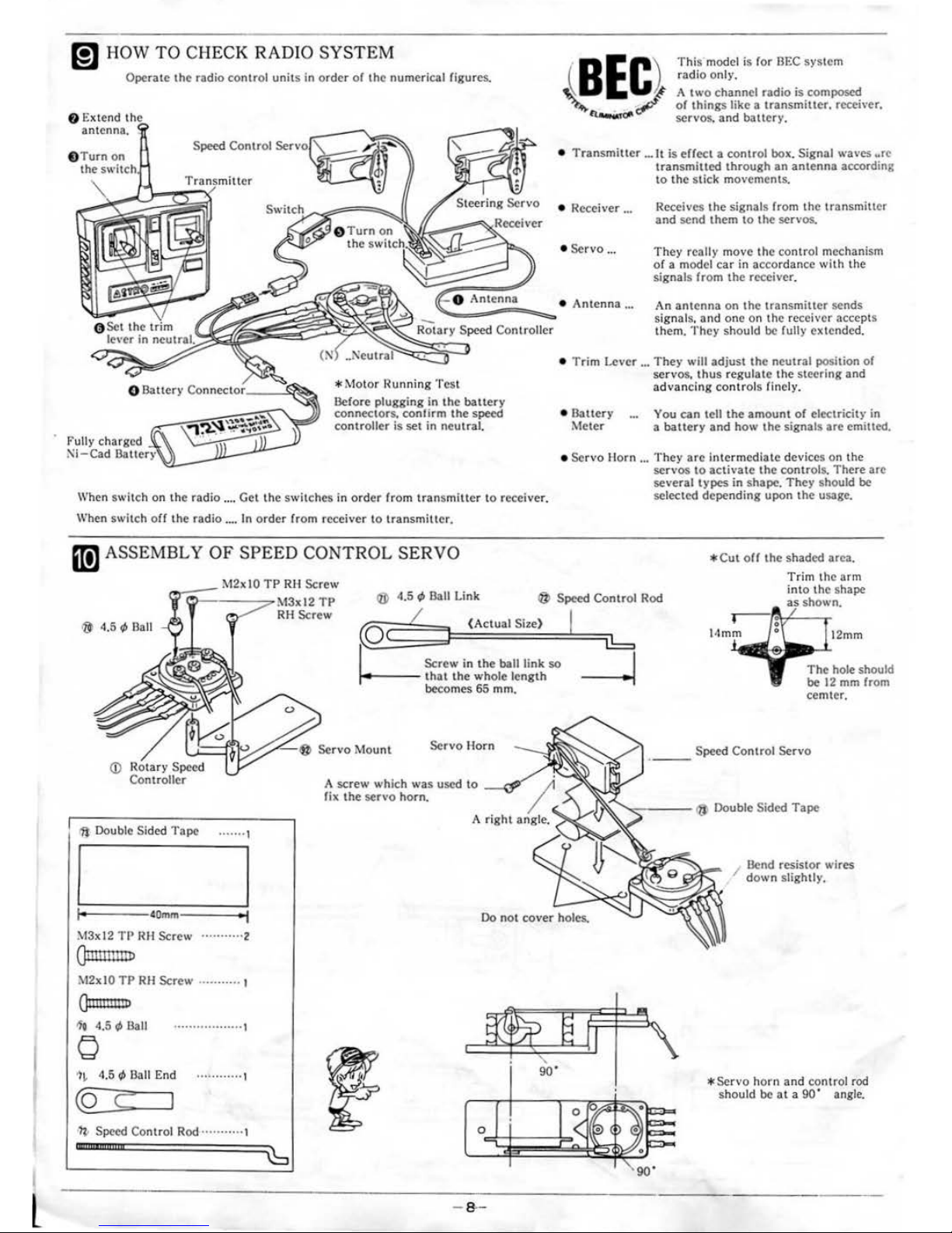
m HOW
TO
CHECK RADIO
SYSTEM
Operate
the
radio
control
units
in
order
or
the
numerical figures.
Tra
tcr
This
model is
for
BEC
system
radio only.
A
two
channel
radio
is composed
or
things
like a
transmiller.
rcceh
·er.
servos.
and
baucry.
•
Transmiuer
...
It
is
effect
a control box. Signal waves
~re
transmilled
through
an
antenna
according
to
the
stick
movements.
• Receiver
...
• Servo
...
Receives the signals from the transmiuer
and
send
them
to
the
servos.
They
really
move the control mechanism
or
a model car in nccordancc
with
the
signals
from
the
receiver.
--
"-.::,=A=n=t"'e,.n
..
n=a=""'.,•
Antenna
...
An
antenna
on
the
transmillcr
sends
signals.
and
one
on
the receiver
accepts
them. They
should
be fu lly extended.
@Set
the
le,
rer
in
ncul
Rotary Speed Controller
*
Motor
l~unning
Test
Before plugging in
the
bauery
connectors.
conlirm
the
speed
controller
is
set
in
neutral.
•
Trim
Lever
...
They
will
adjust
the
neutral
pOsition
or
servos.
thus
regulat
e the
steering
and
advancing
controls
finel
y,
•
Balte
ry
Meter
You
can
tell
the
amount
or
electricity
in
a
baltery
and
how
the
signals
are
emiued.
Fully
charged
Ni-Cad
DattN·v'\ •
Servo Horn
...
They
arc
intermediate
devices
on
the
I
scn•os
to
activate
the
controls.
There
arc
several
types
in
shape.
They
should
be
When switch
on the
radio
....
Get
the swit
ches
in
order
from
tran
smi
ucr
to
receiver. selected
depending
upOn
the
usage.
When switch orr the
radio
....
In order from
receiver
to
transmitt
er.
II!] ASSEMBLY OF
SPEED CONTROL
SERVO
7
0
:::_:l\:_:
1
:::2x::_l:.::O~T~P
R H
Screw
'I
l\13x
12
TP
@
Speed
Control Rod
@ 4.5
1/>
llnll
<D
Rotary Speed
Controller
1ft
Double Sided
Tape
....•.•
1
40mm
I
M3xl2
TP
RH
Screw
...........
2
Qll!lllll
liD
M2x 10
TP
RH
Screw
.....
.......
Qmnnnto
If~
4.5
"'
Ball
•..••••.•
.•..•.•.•
1
0
1~
4.5
1/>
Ball End
• •
•• 0 .....
0 ·1
(Q
(
I
'lt-
Speed Control Rod ....... .... ,
CDIUDIIIIIIIIID
RH
Screw
~~
Screw
in
the
ball link
so
f.----
th
at
the whole
length
becomes
65
mm.
Servo
Mount
Servo
Horn
A
screw
which was used
to
-~
1"'
fix
the
servo
horn
..
I
Do
not
cover
holes.
~
-
8-
--
*Cut
orr
the
shaded
area.
Trim the arm
into
the
shape
shown.
12mm
The
hole should
be 12 mm from
cemter
.
Speed Control
Servo
/ Bend
resistor
wires
down
sli
ght
ly.
* Servo
horn
and
control rod
should
be
at a 90
' angle.
 Loading...