

Page 1
※ご使用前にこの説明書を良くお読みになり
十分に理解してください。
*Before beginning assembly,
*please read these instructions thoroughly.
R
THE FINEST RADIO CONTROL MODELS
INSTRUCTION MANUAL
組立/取扱説明書
1:8 Scale Radio Controlled
Electric Powered 4WD
Monster Truck
目 次 INDEX
●キットの他にそろえる物REQUIRED FOR OPERATION
●プロポの準備RADIO PREPARATION
●組立て前の注意BEFORE YOU BEGIN
●ランナー付プラパーツ配置図ARRANGEMENT OF PLASTIC PARTS ON RUNNERS
●本体の組立てASSEMBLY
●取扱いの注意OPERATING YOUR MODEL SAFELY
●分解図EXPLODED VIEW
●スペアパーツ・オプションパーツリストSPARE PARTS & OPTIONAL PARTS
安全のための注意事項
この無線操縦模型は玩具ではありません!
●この商品は高い性能を発揮するように設計されています。組立てに不慣れな方
は、模型を良く知っている人にアドバイスを受け確実に組立ててください。
●小さい部品があるので、組立て作業は幼児の手がとどかない所で必ずおこなっ
てください。
●動かして楽しむ場所は、万一の事故を考えて安全を確認してから、責任をもっ
てお楽しみください。
●組立てた後も、説明書がいつでも見られるように大切に保管してください。
※製品改良のため、予告なく仕様を変更する場合があります。*SPECIFICATIONS ARE SUBJECT TO BE CHANGED WITHOUT NOTICE.
© 2003 KYOSHO CORPORATION/禁無断転載複製
TWIN FORCE
UNDER SAFETY PRECAUTIONS
This radio control model is not a toy!
●First-time builders should seek the advice of experienced modelers before
beginning assembly and if they do not fully understand any part of the
construction.
●Assemble this kit only in places out of children's reach!
●Take enough safety precautions prior to operating this model.
You are responsible for this model's assembly and safe operation!
●Always keep this instruction manual ready at hand for quick
reference, even after completing the assembly.
2 〜 3
3
4 〜 5
6 〜 7
8 〜 29
30
31 〜 33
34 〜 37
No. 30521B
Page 2
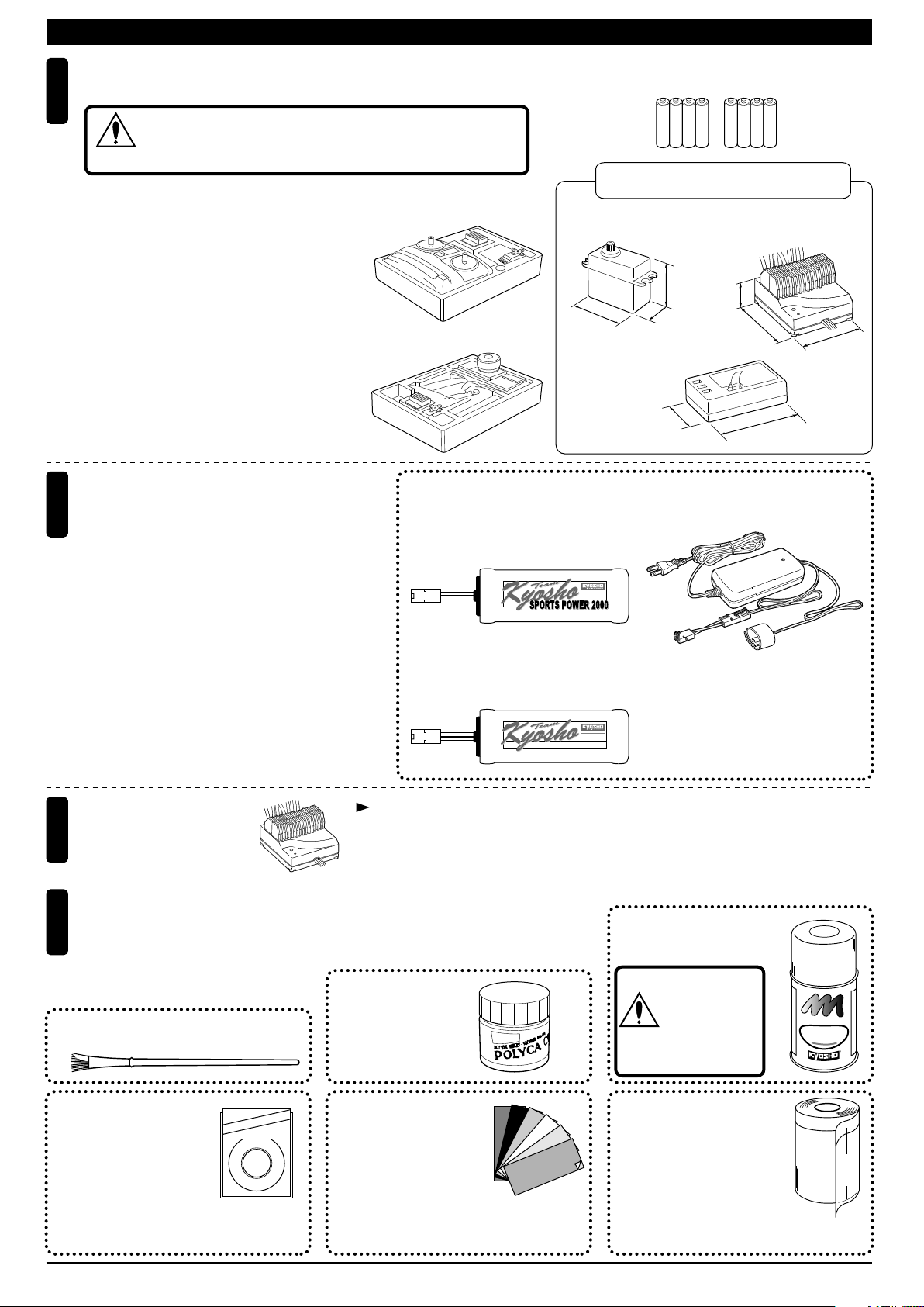
REQUIRED FOR OPERATION (1)キットの他にそろえる物(1)
2チャンネルアンプ仕様無線操縦機(プロポ)と電池
1
2ch with electronic speed controller and 1 servo radio control set
地上用(自動車用)のプロポ(2チャンネルアンプ仕様)セットを
必ず使用してください。(地上用以外使用禁止)
CAUTION: Only use a surface radio with 2 channels and electronic
注意
speed controller! (Any other radio is prohibited!)
●このキットには2チャンネルアンプ仕様
のプロポが必要です。
●送信機にはスティックタイプとハンドル
タイプがありますが、お好みのタイプを
■スティックタイプ
2チャンネルプロポ
Stick-type
2ch radio set
用意してください。
●プロポの取扱いは、プロポに付属の説明
書を参考にしてください。
●This kit requires a 2 channel radio con-
trol set with electronic speed controller.
●Because there are stick-type and wheel-
type transmitters, use which ever fits
■ハンドルタイプ
2チャンネルプロポ
Wheel-type
2ch radio set
your convenience best.
●For more information on the radio con-trol
set, refer to its instruction manual.
走行+受信機用バッテリー、バッテリー充電器
2
Operation/Receiver Battery
and Charger for Ni-Cd Battery
●バッテリーは、2個で車の走行と受信機の電源として
●バッテリーは、2個で車の走行と受信機の電源として
使います。右のバッテリーが純正バッテリーです
使います。右のバッテリーが純正バッテリーです
のでいずれかを使用してください。
のでいずれかを使用してください。
●必ず同じ種類のバッテリーを使用する。
●バッテリー用充電器には、12Vカーバッテリーから
おこなう急速充電器と、家庭のコンセント(100V)
からおこなう急速充電器の2タイプがあります。
Two batteries power the motors and receiver.
Any of the batteries listed at right can be used.
Use only the same type of batteries.
Two types of chargers are available. One operates
on a 12V car battery. The other operates on a 100V
house outlet.
■単3乾電池(送信機用)
AA-size Batteries (For Transmitter)
使用できるサーボ・受信機・アンプサイズ
Suitable servos, receiver & electric speed controller
■サーボ
Servo
38〜41mm
■受信機
Receiver
No.71901
■7.2Vスポーツパワー2000バッテリー
7.2V Sports Power Battery
(Beginner class)
No.71221
■
7.2V スポーツパワー3000 ニッケル水素バッテリー
7.2V SPORTS POWER 3000 Ni-MH Battery
RECHARGEABLENi‑CdBATTERY
(入門タイプ)
KYOSHOCORPORATIONNO.71901
AAAA
■アンプ
Electric speed controller
31〜36mm
20〜22mm
18〜20mm
29〜32mm
No.72021
■XチャージャーAC
X-CHARGER AC
No.72102
■
エクセルプロチャージャーVor.2.0
EXCEL PRO CHARGER Vor.2.0
No.72511
■マルチチャージャーIV
Mulci Charger IV
AAAA
50〜58mm
38〜48mm
43〜48mm
アンプ
3
Electric Speed Controller
塗料と筆
4
Paint and Brush
●ボディの塗装には塗料が必要です。
京商では、モデル用塗料、スプレーを
用意していますのでご利用ください。
For painting the body, use Kyosho paints
for models!
■筆
PAINT BRUSH
ミクロンラインテープ
MICRON LINE TAPE
No.1841
マスキング、細部デザイ
ン用伸縮自在テープです。
1842
1843
1859
1860
(1mm x 5m)
(1.5mm x 5m)
(2.5mm x 5m)
(0.4mm x 8m)
(0.7mm x 8m)
Super-flexible tape for
masking and detail designing jobs.
各社7.2Vバッテリー×2(14.4V)仕様のアンプが必要です。
Requires an ESC designed for two 7.2V batteries (14.4V).
No.76301〜76711
京商スプレーカラー
KYOSHO SPRAY COLOR
注意
スプレーカラーを
使用する場合、缶
の説明を良く読ん
でください。
CAUTION: Before
using spray colors,
always read their
explanations!
E
N
U
L
I
P
R
A
O
P
F
F
F
T
K
O
Y
H
S
O
S
P
R
O
R
L
A
O
Y
C
R
No.2230
ポリカカラー
POLYCA COLOR
pe
Ta
e
n
Li
cron
i
M
KYOSHO
No.96701
D‑フレックスカラーデカール
D FLEX COLOR DECAL
伸縮自在の特殊素材で3次曲面
にもきれいに貼れる粘着シートです。
Self-adhesive super-flexible sheets that
bond to polycarbonate - even when
applied to curved surfaces.
No.1947
マスキングカバーシート
MASKING SHEET
マスキングテープとビニール
シートが一体になった広範囲
マスク用テープです。
For safe masking jobs, use this plastic masking sheet featuring one self-adhesive edge.
2
Page 3

キットの他にそろえる物(2)REQUIRED FOR OPERATION (2)
組立てに必要な工具
Tools required
6
■+ドライバー(大、中、小)
Phillips Screwdriver (L.M.S)
■カッターナイフ
Sharp Hobby Knife
キットに入っている工具
TOOLS INCLUDED
■六角レンチ(1.5mm,2mm,2.5mm,3mm)
Hex Wrench (1.5mm, 2mm, 2.5mm, 3mm)
■十字レンチ(大)
Cross Wrench
■ラジオペンチ
Needle Nose Pliers
■ニッパー
Wire Cutters
■キリ
Awl
No.695101
ナイフエッジリーマー
Knife REAMER
下穴加工が不要で、直接
1mm〜15mmの正確な穴
あけができる工具です。
■ネジロック剤
Screw Cement
ネジロック剤
■ゴム系接着剤
Rubber Cement
ゴム系接着剤
No need to pre-drill!
Drills neat 1mm to 15mm
holes directly!
使用する工具の取扱いには、
十分注意してください。
CAUTION: Handle tools carefully!
注意
KYOSHO スペシャルグルー
KYOSHO Special Glue
瞬間接着剤
Instant Glue
No.96154
No.1829
ラウンドカッター&サンダー
ROUND CUTTER & SANDER
ボディのカット、仕上
げ用。曲線部分も楽に
作業ができます。
For trimming bodies!
Cutting along curved lines
never was so easy!
KYOSHO
Special Glue
プロポの準備 RADIO PREPARATION
●キットの組立てに入る前に、バッテリーを充電器の説明にしたがって充電しておきます。
A new battery must be charged before it is used. Refer to the charger instruction manual for charging.
●プロポを下の順番にしたがってセットします。
Set up the radio control system as indicated below.
▲バッテリー×2個
Battery x 2
ON
6
10
2
OFF
5
8
1
●始める時
3
11
2
11
8
送信機
5
▲
Transmitter
1
ON
6
10
OFF
1
単3乾電池をセットする。(送信機)
アンテナをのばす。(送信機)
2
バッテリーをつなぐ。
3
アンテナをのばす。(受信機)
4
トリムレバーを中央にセットする。
5
スイッチを入れる。(送信機)
6
スイッチを入れる。(受信機)
7
スティックを動かしてサーボが動くか確認する。
8
▲充電器
Charger
▲サーボ
Servo
●START
▲受信機
Receiver
1
2
3
4
5
6
7
8
▼アンプ
Electronic Speed Controller
7
9
▲スイッチ
Switch
4
Install batteries. (Transmitter)
Extend the antenna. (Transmitter)
Connect the battery.
Extend the antenna. (Receiver)
Center the trims.
Switch on. (Transmitter)
Switch on. (Receiver)
Make sure the servos are in command.
ON
OFF
●終わる時
9
スイッチを切る。(受信機)
10
スイッチを切る。(送信機)
11
アンテナを縮める。(送信機)
●FINISH
Switch off. (Receiver)
9
Switch off. (Transmitter)
10
Retract the antenna. (Transmitter)
11
3
Page 4

組立て前の注意(1) BEFORE YOU BEGIN (1)
組立てる前に説明書を良く読んで、おおよその構造を理解してから組立てに入ってください。
1
Read through the manual before you begin, so you will have an overall idea of what to do.
キットの内容をお確かめください。万一不良、不足がありましたら、お買い求めの販売店にご相談いただくか、当社「ユーザー相談室」までご連絡ください。
2
Check all parts. If you find any defective or missing parts, contact your local dealer or our Kyosho Distributor.
説明書の見かた
3
How to read the instruction manual:
〔説明例Example〕
説明書内では多くのマークが使用
フロントサスペンション
Front Suspension
1
4
5 x 10mm メタル
Metal Bushing
No.4, No.5, No.6
1
されています。マークに注意して
組立てを進めてください。
This instruction manual uses several symbols. Please note them
during the entire assembly.
4
キングピン
5
King Pin
4
5.8mm ピロボール(黒)
6
Pillow Ball (Black)
2
小物部品の名前、原寸図、使用数。
Key Number, Part Name, True-to-scale
Diagram, Quantity Used
説明書に使われているマーク
4
Symbols used throughout the instruction manual, comprise:
使用する袋詰。
Part bags used.
キット内の部品は、ビス類を除いてキー
No.が付けられています。スペアパーツを
購入する時はキーNo.を参照して下さい。
All parts except screws are identified by
key numbers. For purchasing spare parts,
find the key no. of the part needed in the
spare part list and refer to the left column
to look up the corresponding order no.
4
2mm
3
6
2mmの穴をあける(例)。
Drill holes with the specified
diameter (here: 2mm).
5
7
R
L
5
8
別購入品
Must be purchased separately!
2
x2
瞬間接着剤で接着する。
Apply instant glue (CA glue, super glue).
グリスを塗る。
Apply grease.
ネジロック剤を塗る。
Apply threadlocker (screw cement).
2セット組立てる(例)。
Assemble as many times as
specified (here: twice).
ゴム系接着剤で接着する。
Apply rubber cement.
余分をカットする。
Cut off excess.
をカットする。
Cut off shaded portion.
仮止め。
Tentatively tighten.
可動するように組立てる。
Ensure smooth non-binding
movement while assembling.
注意して組立てる所。
Pay close attention here!
番号の順に組立てる。
Assemble in the specified
order.
原寸図
True-to-scale diagram.
左右同じように組立てる。
Assemble left and right sides
the same way.
4
Page 5
組立て前の注意(2) BEFORE YOU BEGIN (2)
キットには、形や長さが違うビスや小物部品が多く入っています。説明書には原寸図がありますので確認してから組立ててください。
5
また、ビス類は多めに入っているものもありますので、予備としてお使いください。
This kit contains screws and hardware in different metric sizes and shapes.
Before using them, check the screws on the true-to-scale diagrams on the left side in each assembly step. Some screws are extras.
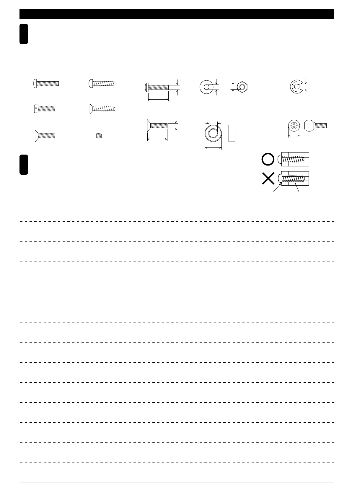
●ビスの種類 SCREWS
ビス Screw
キャップビス
Cap Screw
サラビス
Flat Head (F/H) Screw
TPビスは、部品にネジを切りながらしめつけるビスです。しめこみが固い場合がありますが、
6
部品が確実に固定されるまでしめこんでください。ただし、しめすぎるとネジがきかなくなり
ますので、部品が変形するまでしめないでください。
Self-tapping (TP) screws cut threads into the parts when being tightened. Excessive force may
permanently damage parts when tightening TP screws. It is recommended to stop tightening when
the part is attached or when some resistance is felt after the threaded portion enters the plastic.
TPビス
Self-tapping (TP) Screw
TPサラビス
TP F/H Screw
セットビス
Set Screw
●小物部品のサイズ例 OTHER HARDWARE
3x12mmビス
Screw
12mm
3x12mmサラビス
F/H Screw
3mm
12mm
3mmワッシャー・ナット
Washer・Nut
3mm
5x10mmメタル・ベアリング
Metal Bushing・Bearing
5mm
10mm
MEMO
3mm
Correct
Wrong
しめすぎ
Overtightened.
E3Eリング
E-ring
3mm
6.8mmピロボール
Pillow Ball
6.8mm
ビスがきかない
The threads are stripped.
5
Page 6
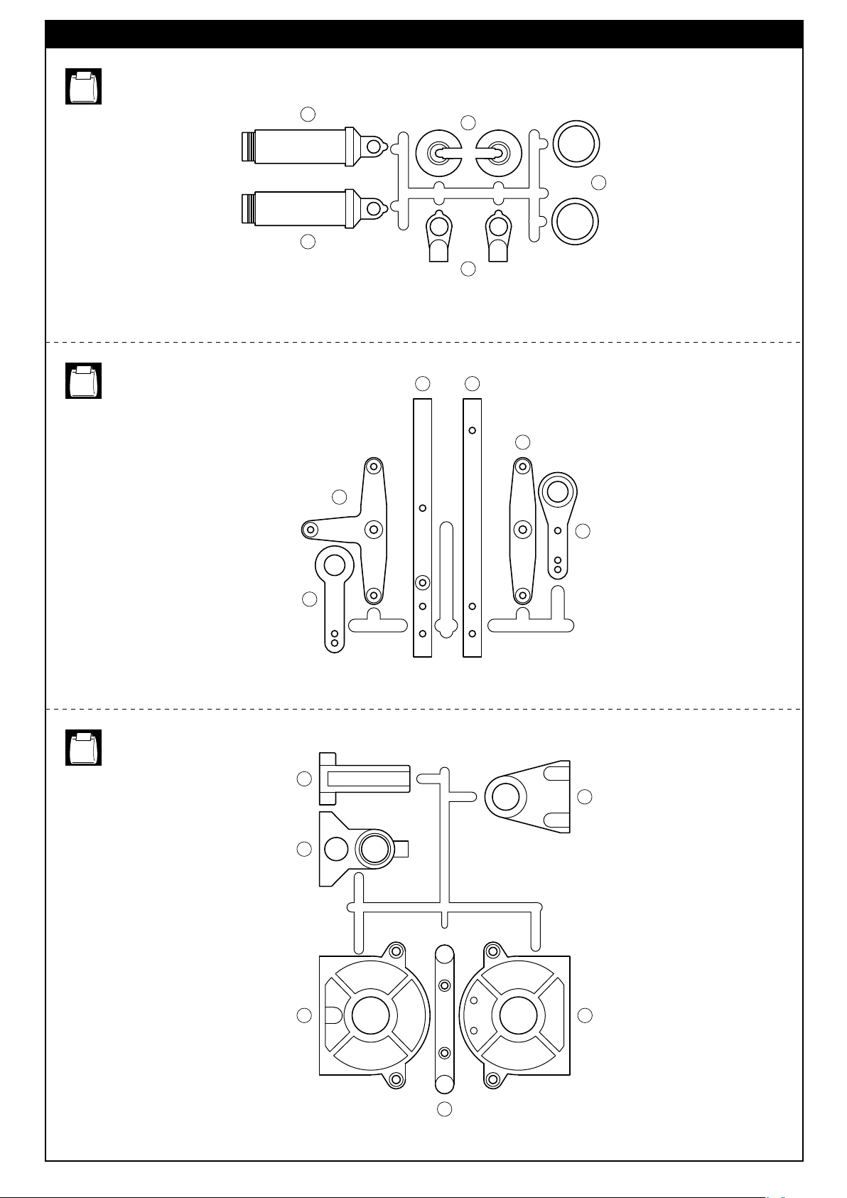
ランナー付プラパーツ配置図(1)/
No.1
ARRANGEMENT OF PLASTIC PARTS ON RUNNERS (1)
No.3
30
30
34
32
29
77 76
115
114
No.5
45
44
48
62
57
4954
59
6
Page 7

ランナー付プラパーツ配置図(2)/
No.1
ARRANGEMENT OF PLASTIC PARTS ON RUNNERS (2)
No.7
33
33
33
33
5
33
5 2 2
33
33
1 1 1 1
33
10 10
33
33
2 2
33
33
79
No.6
96
94
92
部分の部品は、使用しません。
Shaded Parts are not used.
102
97
103
97
97
103
97
101
99
98
100
7
Page 8

〜は組立済です。
1 6
Parts are pre-assembled in step ~ .
1 6
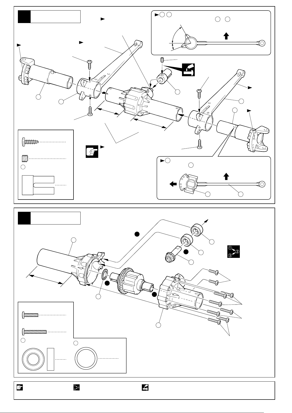
デフギヤ
Gear Differential
1
4 x 4mm
Set Screw
11
6 6mm
4 2.6 x 14mm
2
3 x 10mm
TP F/H Screw
4 2.6 x 14mm
6 6mm
セットビス
4 x 10mm
Shim
O-ring
Shaft (Black)
Shaft (Black)
O-ring
シム
Oリング
シャフト(黒)
デフギヤ
Gear Differential
TPサラビス
シャフト(黒)
Oリング
2
4
5 8 x 16mm
Ball Bearing
2
2
2
8
5 8 x 16mm
Ball Bearing
2
2
8
5
ベアリング
2
6
ベアリング
4x4mm
10
9
11
4
1
3
10
11
2
4
1
6
2
2
x2
4
1
5
8
2
12
デフオイル
Diff. Oil
15
3x10mm
x2
フロントアクスル
Front Axle
3
2.6x16mm
2.6x16mm
2.6x16mm
2.6 x 10mm
Screw
2.6 x 16mm
Screw
5 8 x 16mm
Ball Bearing
ビス
ビス
ベアリング
2.6x10mm
2
7
21
13 x 16mm
Shim (Thick)
2
13
短い方
Short
シム(厚)
3
5
2
5
7
1
21
1
4
長い方
Long
14
x2
2セット組立てる(例)。番号の順に組立てる。 グリスを塗る。
Assemble as many times as specified.Assemble in the specified order. Apply grease.
別購入品。
Must be purchased separately!
8
Page 9
フロントサスアーム
Front Suspension Arm
4
Fのマーク
Marked “F”
19
3x10mm
17
Aのマーク
Marked “A”
平らな面にセットビス
を固定する。
Install a setscrew on
the flat surface.
, は向きに注意。
17 18
Pay attention to the direction of & .
広い
Wide
狭い
Narrow
5x4mm
17 18
3x10mm
16
上
Up
B
Bのマーク
Marked “B”
18
3 x 10mm
TP Screw
5 x 4mm
Set Screw
16
ジョイントカップ
Joint Cup
TPビス
セットビス
リヤアクスル
Rear Axle
5
3x10mm
4
1
1
14
短い方
Short
長さに注意。
Pay attention to the lengths.
3
長い方
Long
19
3x10mm
が図の角度になるように固定穴に注意する。
19
The angle of must be as shown in the drawing.
Use the correct hole.
前
Front
19
上
F
Up
5
1
5
Fのマーク
Marked “F”
F
1819
長い方
Long
2.6 x 10mm
Screw
2.6 x 16mm
Screw
5 8 x 16mm
Ball Bearing
注意して組立てる所。
Pay close attention here!
ビス
ビス
ベアリング
21
2
7
21
13 x 16mm
Shim (Thick)
2
番号の順に組立てる。
Assemble in the specified order.
シム(厚)
7
2
2.6x10mm
4
2.6x16mm
2.6x16mm
13
短い方
Short
2.6x16mm
1
ネジロック剤を塗る。
Apply threadlocker (screw cement).
9
Page 10

リヤサスアーム
Rear Suspension Arm
6
Rのマーク
Marked “R”
24
3x10mm
17
Aのマーク
Marked “A”
狭い
Narrow
5x4mm
平らな面にセットビス
を固定する。
Install a setscrew on
the flat surface.
, は向きに注意。
17 18
Pay attention to the direction of & .
広い
Wide
17 18
3x10mm
16
上
Up
B
Bのマーク
Marked “B”
18
3 x 10mm
TP Screw
5 x 4mm
Set Screw
TPビス
セットビス
ダンパー
Shock
7
26
Oリング(中)
29
ダンパーエンド
3x10mm
16
4
1
O-ring (M)
Shock End
ジョイントカップ
Joint Cup
4
4
1
No.1
25
27
長い方
Long
組み立て開始
短い方
Short
長さに注意。
Pay attention
to the lengths.
START
26
オイルを少し付ける。
Put a little oil.
Rのマーク
Marked “R”
R
3x10mm
24
40mm
29
傷を付けないように
注意する。
Pinch to avoid scratching
the shock shaft.
x4
ダンパー
Shock
8
No.1
オイルを入れる。
1
Put the oil.
30
使用する袋詰。 4セット組立てる(例)。
Part bags used.
ネジロック剤を塗る。 注意して組立てる所。
Apply threadlocker (screw cement). Pay close attention here!
伸ばしておく。
2
Keep expanded.
キャップが軽く止
3
まる所まで締め、
1/2回転ゆるめる。
Tighten the cap until it
slightly stops,
then loosen it for a
1/2nd lap.
シャフトをゆっくり押し込む。
4
Insert the shaft slowly.
余分なオイル
が出る。
Surplus oil comes out.
x4
Assemble as many times as specified.
キャップを最後まで
5
締め込み、シャフト
を伸ばす。
Tighten the cap firmly,
and pull the shaft.
10
Page 11
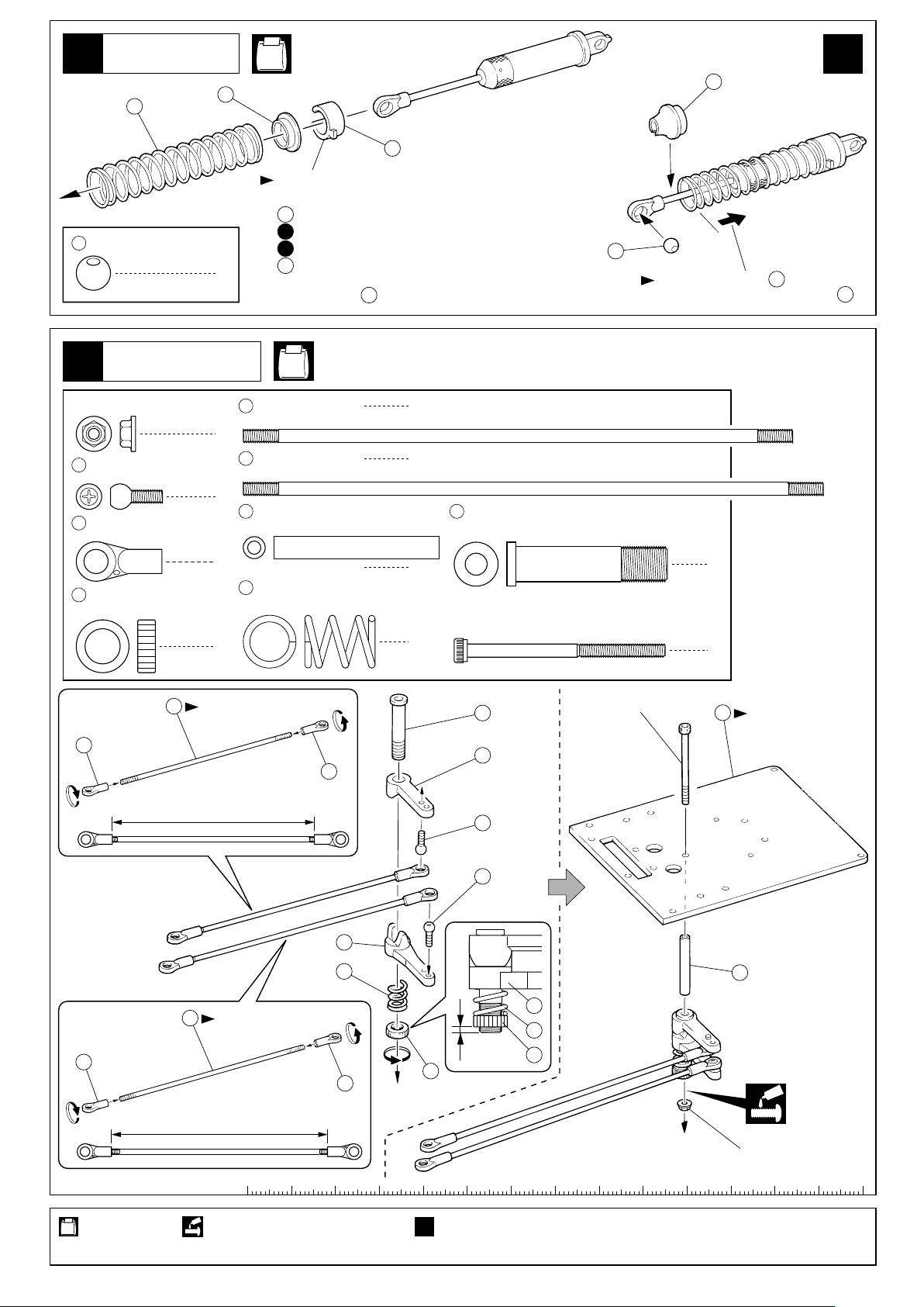
ダンパー
Shock
9
35
7.8mm
Ball
31
ボール
32
4
No.1
33
スプリング調整用。
For adjusting the spring tension.
は5種類あるので………
33
1
車高の前後が、水平になるように
2
走行しながら………種類、個数を調節する。
exists in 5 widths. For making the F / R ground
33
clearance horizontal, choose the necessary width(s)
and amount of . When adjusting, run your car.
33
34
35
スプリングを縮めて を入れる。
Compress the spring and install .
x4
34
34
サーボセイバー
Servo Saver
10
3mm
フランジ付ナット
Flanged Nut
5.8mm
36
37
38
ピロボール(銀)
Pillow Ball (silver)
5.8mm
ボールエンド
Ball End
セイバーナット
Saver Nut
39
37
39
3 x 125mm
Rod
1
40
3 x 132mm
Rod
2
41
5 x 37.5mm
Shaft
4
43
サーボセイバースプリング
Servo Saver Spring
1
短い方
Short
約115mm
approx. 115mm
No.3, No.5
ロッド
ロッド
シャフト セイバーシャフト
1
1
42
Saver Shaft
1
3 x 45mm
Cap Screw
1
キャップビス
42
44
37
36
3x45mm
1
1
46
向きに注意。
Note the direction.
37
使用する袋詰。
Part bags used.
36
45
43
40
長い方
Long
2mm
37
約123mm
approx. 123mm
ネジロック剤を塗る。 4セット組立てる(例)。
Apply threadlocker (screw cement).
38
x4
Assemble as many times as specified.
41
45
43
38
3mm
11
Page 12

11
ギヤボックス
Gearbox
No.3, No.5
53
5x4mm
3
3 x 12mm
Screw
3 x 8mm
Screw
3 x 10mm
TP Screw
5 x 4mm
Set Screw
51
2.6 x 16mm
Pin
55
ジョイントカップ
Joint Cup
52
センターシャフト
Center Shaft
ビス
ビス
TPビス
セットビス
ピン
10
2
4
1
1
1
47
3x10mm
48
3x12mm
3x10mm
49
50
51
52
1
55
5
2
4
6
5
54
5
7
3x10mm
3x10mm
46
56
6 x 12 x 4mm
Ball Bearing
5
8 x 16mm
Ball Bearing
ドライブチェーン
50
Drive Chain
26T
スプロケット
53
Sprocket
ベアリング
ベアリング
1
1
57
向きに注意。
2
56
Note the direction.
58
59
1
3x10mm
使用する袋詰。
Part bags used.
12
1
ネジロック剤を塗る。
Apply threadlocker (screw cement).
3x8mm
番号の順に組立てる。
Assemble in the specified order.
3x8mm
3x10mm
Page 13

ギヤボックス
Gearbox
12
No.5
3 x 10mm
TP Screw
4 x 4mm
Set Screw
56
6 x 12 x 4mm
Ball Bearing
TPビス
セットビス
ベアリング
1
ドライブチェーンに
60
スプロケットを引っかける。
Hook the Drive Chain on Sprocket.
60
ドライブチェーン
2
2
1
Drive Chain
60
4x4mm
61
4x4mm
2
62
3x10mm
56
3
63
メインギヤ
Main Gear
13
4mm
フランジ付ナイロンナット
Flanged Nylon Nut
68
6 x 10 x 3mm
Metal Bushing
メタル
64
4mm
モーター
Motor
14
65
66
No.5
1
66
1
69
67
約7mm
approx. 7mm
68
67
スパーギヤの凹部へ をはめ込む。
69 67
67
Install to the indented part of .
69
No.5
3 x 8mm
Cap Screw
3 x 3mm
Set Screw
3mm
Washer
使用する袋詰。
Part bags used.
キャップビス
セットビス
ワッシャー
4
2
4
ギヤのかみ合わせ(バックラッ
シュ)は、紙1枚分のすき間を
つくって固定する。
Gears should engage firmly,
leaving a gap only wide enough
to insert a piece of paper.
ネジロック剤を塗る。
Apply threadlocker
(screw cement).
3mm
3x8mm
3x3mm
70
番号の順に組立てる。
Assemble in the specified order.
3mm
3x8mm
左右同じように組立てる。
Assemble left and right
sides the same way.
71
可動するように組立てる。
Ensure smooth, non-binding
movement when assembling.
13
Page 14

サイドプレート
Side Plate
15
< >右側用
< >
Right
No.6
72
向きに注意。
Note the direction.
は平らな面を に合わせる。
73 72
The flat surfaces of parts
must rest against part .
73
72
前
Front
3 x 8mm
Cap Screw
3 x 10mm
Cap Screw
73
シャシージョイント
Chassis Joint
16
キャップビス
キャップビス
バッテリーボックス
Battery Box
< >右側用
< >Right
4
4
4
< >左側用
< >
Left
No.7
73
3x8mm
74
73
72
向きに注意。
Note the direction.
3x10mm
3x8mm
3x10mm
74
前
Front
3 x 8mm
F/H Screw
3mm
Flanged Nut
使用する袋詰。
Part bags used.
サラビス
フランジ付ナット
< >左側用
< >Left
4
4
仮止め。
Tentatively tighten.
3mm
75
左右同じように組立てる。
Assemble left and right sides the same way.
3mm
注意して組立てる所。
Pay close attention here!
3x8mm
ネジロック剤を塗る。
Apply threadlocker (screw cement).
3x8mm
14
Page 15

サイドプレート
Side Plate
17
前
Front
右側用
For Right
3x10mm
3 x 10mm
Cap Screw
メインシャシー
Main Chassis
3x10mm
メインシャシーを取付後、3x10mmキャップ
ビスにネジロック剤を塗って本締めします。
Attach the side plates to the main chassis by
installing the six 3x10mm cap screws. Screw
them in completely and use screw cement.
キャップビス
左側用
For Left
3x10mm
4
ステアリングサーボ
Steering Servo
18
76
3x10mm
約1mm
approx. 1mm
78
77
3x10mm
サーボ付属。
Supplied with
the servo.
No.3, No.7
ステアリングサーボ
Steering Servo
2mm
1
3x10mm
約20mm
approx. 20mm
90
1
3x12mm
2
各社サーボホーンを
図の様にカットする。
Servo horns by any
manufacturer should
be cut as shown in
the drawing.
1
1
3x12mm
3x10mm
3 x 10mm
TP Screw
5.8mm
78
Pillow Ball (Black)
3 x 12mm
F/H TP Screw
TPビス
6
ピロボール(黒)
1
TPサラビス
2
使用する袋詰。
Part bags used.
ネジロック剤を塗る。
Apply threadlocker
(screw cement).
2mmの穴をあける(例)。
2mm
Drill holes with the
specified diameter.
をカットする。
Cut off shaded portion.
別購入品。
Must be purchased
separately!
番号の順に組立てる。
Assemble in the
specified order.
左右同じように組立てる。
Assemble left and right
sides the same way.
15
Page 16

19
プロポ
Radio
No.7
3x10mm
3x10mm
79
3 x 10mm
TP Screw
20
TPビス
プロポ
Radio
No.7
3
両面テープ
Double-sided Tape
と を間違えない
様に接続する。
Be careful to avoid mixing
up the and leads.
14.4Vアンプ
14.4V Electronic Speed Controller
受信機
Receiver
90
使用する袋詰。
Part bags used.
16
別購入品。
Must be purchased separately!
注意して組立てる所。
Pay close attention here!
90
両面テープ
Double-sided Tape
左右同じように組立てる。
Assemble left and right sides the same way.
Page 17

プロポ
Radio
21
2 x 8mm
Screw
2mm
Nut
3 x 10mm
TP Screw
ビス
ナット
TPビス
アンテナ
Antenna
91
2
2
1
3x10mm
No.7
スイッチに付属のビス。
Included with the switch.
サーボコードを通す。
Cords come like picture.
スイッチに付属でない場合は、
2x8mmビス、2mmナットで
取り付ける。
If screws are not included with
the switch, use a 2x8mm screw
and a 2mm nut.
スイッチに付属のプレート。
Included with the switch.
スイッチ
Switch
プロポの説明書を参考に、
コネクターを接続する。
Connect as per radio
instruction manual.
22
プロポ
Radio
92
コードが短い場合は各プロポメーカー
より発売の延長コードを使用する。
If the wire is too short, use extension wire
available from your radio manufacturer.
コードをストラップで束ねる。
Bind the wires with strap.
95
93
No.7
フックピン
93
Hook Pin
3
コード類を挟まないように注意する。
Be careful not to snag the wires.
高温時など、アンプのヒートプロテクター
が作動する場合は取り外します。
Remove when the heat protector
of your ESC is used.
使用する袋詰。
Part bags used.
別購入品。
Must be purchased separately!
93
93
94
注意して組立てる所。
Pay close attention here!
17
Page 18

フロントバンパー
Front Bumper
23
No.6
一番下の穴。
Use the lowest hole.
3x12mm
97
98
2x8mm
2x8mm
98
2x8mm
2 x 8mm
TP Screw
3 x 12mm
Screw
TPビス
ビス
ウイリーバー
Wheelie Bar
24
No.6
一番下の穴。
Use the lowest hole.
2
4
111
99
2x8mm
96
2x8mm
97
97
3x12mm
99
3x12mm
2x8mm
100
101
103
3x12mm
103
102
3x12mm
2 x 8mm
TP Screw
3 x 12mm
Screw
3mm
Flanged Nut
使用する袋詰。
Part bags used.
TPビス
ビス
フランジ付ナット
18
14
2
4
3x12mm
3mm
3mm
104
アルミ製
Aluminum
3x12mm
Page 19

フロントサスペンション
Front Suspension
25
No.3
5 8 x 16mm
Ball Bearing
106
2.6 x 13.8mm
Pin
127
6mm
Flanged Nut
ベアリング
ピン
フランジナット
“R”のマーク
“R” maked.
< >右側用
4
2
2
< >Right
127
106
3
1
2
5
108
5
107
105
向きに注意。
Note the direction.
109
< >左側用
< >Left
“L”のマーク
“L” maked.
110
フロントサスペンション
Front Suspension
26
4 x 12mm
Cap Screw
111
キャップビス
ナックルカラー
Knuckle Collar
111
右側用
For right side.
4x12mm
111
No.3
4
4x12mm
4
フロント用
For Front
111
113
長いシャフト
Long
“F”のマーク
“F” maked.
111
左側用
For left side.
長い方
F
4x12mm
短い方
Short
112
短いシャフト
Short
Long
4x12mm
長さに注意。
Pay attention to the lengths.
使用する袋詰。
Part bags used.
左右同じように組立てる。
Assemble left and right
sides the same way.
番号の順に組立てる。
Assemble in the
specified order.
注意して組立てる所。
Pay close attention here!
仮止め。
Tentatively tighten.
19
Page 20

27
ステアリング
Steering
37
128
短い方
Short
No.3
37
37
129
37
長い方
Long
約32mm
approx. 32mm
5.8mm
36
37
128
129
ピロボール(銀)
Pillow Ball (silver)
5.8mm
ボールエンド
Ball End
3 x 51mm
Rod
3 x 94mm
Rod
ロッド
ロッド
ステアリング
Steering
28
x2
約78mm
approx. 78mm
36
36
5
約1mm
approx. 1mm
6
36
36
約1mm
approx. 1mm
115
114
2
1
No.3
36
約1mm
approx. 1mm
3x18mm
3 x 18mm
Cap Screw
3mm
Washer
5.8mm
36
Pillow Ball (silver)
116
3 x 4.5 x 8.5mm
Collar
3mm
Flanged Nut
キャップビス
ワッシャー
ピロボール(銀)
カラー
フランジ付ナット
“L”のマーク
“L” maked.
短い方
Short
2
2
2
長い方
Long
3x18mm
3mm
3mm
116
116
2
3mm
36
2
3mm
F
“F”のマーク
“F” maked.
長い方
Long
短い方
Short
36
“R”のマーク
“R” maked.
短い方
Short
長さに注意。
Pay attention to
the lengths.
使用する袋詰。
Part bags used.
20
2セット組立てる(例)。
x2
Assemble as many
times as specified.
Ensure smooth, non-binding
movement when assembling.
ネジロック剤を塗る。可動するように組立てる。
Apply threadlocker
(screw cement).
注意して組立てる所。
Pay close attention here!
Page 21

フロントサスペンション
Front Suspension
29
No.6
3 x 25mm
Cap Screw
117
サスピボット
Suspension Pivot
3mm
Flanged Nut
3 x 10 x 1mm
Washer
キャップビス
フランジ付ナット
ワッシャー
3mm
2
2
2
1
2
2
3x25mm
117
2
3mm
3mm
3x25mm
117
118
3
フロントダンパー
Front Shock
30
3 x 20mm
Screw
3mm
Nylon Nut
ビス
ナイロンナット
ダンパー
Shocks
2
2
○印のある方から押し込む。
Push on marked side first.
ダンパー
Shocks
3mm
3x20mm
この穴を使う。
Use this hole.
使用する袋詰。
Part bags used.
番号の順に組立てる。 ネジロック剤を塗る。
Assemble in the specified order. Apply threadlocker (screw cement).
左右同じように組立てる。
Assemble left and right
sides the same way.
21
Page 22

リヤサスペンション
Rear Suspension
31
5 8 x 16mm
Ball Bearing
119
6.8mm
Ball End (L)
ベアリング
ボールエンド(L)
106
2.6 x 13.8mm
Pin
120
6.8mm
4
Ball
3 x 12mm
Cap Screw
4
キャップビス
No.4
127
ピン フランジナット
ボール
6mm
Flanged Nut
2
4
2
120
x2
120
2
119
4x25mm
119
約10mm
approx. 10mm
4 x 25mm
Set Screw
セットビス
3
127
105
リヤサスペンション
Rear Suspension
32
3 x 12mm
Cap Screw
111
ナックルカラー
Knuckle Collar
キャップビス
1
< >左側用
< >Left
2
106
2
107
向きに注意。
Note the
direction.
4 x 12mm
Cap Screw
2
4
キャップビス
110
5
No.4
“L”のマーク
“L” maked.
3x12mm
4
5
リヤ用
For Rear
109
112
短いシャフト
Short
4x12mm
< >右側用
< >Right
“R”のマーク
“R” maked.
108
111
111
左側用
For left side.
使用する袋詰。
Part bags used.
22
111
3x12mm
2セット組立てる(例)。
x2
Assemble as many
times as specified.
4x12mm
“R”のマーク
“R” maked.
R
4x12mm
原寸図。
True-to-scale
diagram.
長い方
Long
113
長いシャフト
Long
左右同じように組立てる。
Assemble left and right
sides the same way.
短い方
Short
番号の順に組立てる。
Assemble in the
specified order.
111
3x12mm
4x12mm
長さに注意。
Pay attention to the lengths.
注意して組立てる所。
Pay close attention
here!
右側用
For right side.
仮止め。
Tentatively tighten.
Page 23

リヤサスペンション
Rear Suspension
33
No.4
3 x 25mm
Cap Screw
117
サスピボット
Suspension Pivot
3mm
Flanged Nut
3 x 10 x 1mm
Washer
キャップビス
フランジ付ナット
ワッシャー
3mm
2
2
2
3x25mm
2
3mm
2
117
2
3mm
3x25mm
1
117
118
リヤダンパー
Rear Shock
34
3 x 20mm
Screw
3mm
Nylon Nut
ビス
ナイロンナット
ダンパー
Shocks
2
2
○印のある方から押し込む。
Push on marked side first.
ダンパー
Shocks
3mm
3x20mm
この穴を使う。
Use this hole.
使用する袋詰。
Part bags used.
番号の順に組立てる。 ネジロック剤を塗る。
Assemble in the specified order. Apply threadlocker (screw cement).
左右同じように組立てる。
Assemble left and right
sides the same way.
23
Page 24

タイヤ
Wheels
35
< >左側用 < >右側用
< >Left < >Right
同じ向きの物を4つ組立てないようにする。
Assemble 2 wheels for the left and 2 wheels for the right side.
121
ゴム系ボンドにて接着
してタイヤ内へ入れる。
Apply rubber cement
and install in tires.
123
向きに注意。
Note the
direction.
121
向きに注意。
Note the direction.
2mm
122
x2
x4
タイヤとの接着面の
メッキをサンドペー
パー等で落とす。
Sand the gilding from
the shaded portion of
the wheels.
2mm2mm
x2
122
2mmの穴を2ヶ所開ける。2mmの穴を2ヶ所開ける。
Make two 2mm holes.Make two 2mm holes.
2mm
36
タイヤ
Wheels
右側用
For right side.
右側用
For right side.
左側用
For left side.
左側用
For left side.
127
127
いったん外して取り付け直します。
Remove when adjust.
Apply instant glue
(CA glue, super glue).
24
2mmの穴をあける(例)。瞬間接着剤で接着する。
2mm
Drill holes with the
specified diameter.
2セット組立てる(例)。
x2
Assemble as many
times as specified.
左右同じように組立てる。
Assemble left and right
sides the same way.
注意して組立てる所。
Pay close attention
here!
ゴム系接着剤で接着する。
Apply rubber type glue.
Page 25

37
ボディ
Body Shell
124
7mm
6mm
7mm
塗装
Painting
38
塗装前に、洗剤で油やよごれを洗う。 ウインドウ部分に、内側から
1
Before painting, use a neutral detergent
to remove any oil residues and dirt.
塗分けはパッケージ写真も
3
参考にしてください。
Refer to the pictures on the
box for the color scheme.
京商スプレーカラーで
ボディ内側を塗装する。
Paint the body shell from the inside
using Kyosho’s spray colors.
マスキング
Mask Windows
2
マスキングシートを貼る。
Mask the windows from the inside.
塗装後、ボディ表面の保護ビニール
4
シートをはがしておく。
After painting, remove the protective
film from the body shell.
マスキング
Mask Windows
Cut off shaded portion.
7mmの穴をあける(例)。 をカットする。
7mm
Drill holes with the specified diameter.
25
Page 26

デカール
Decals
39
1 2
7 8 69
16 17
図の位置に から順にデカール
をはる。
Apply the decals to the positions
indicated in numerical order.
1 カッコの中は反対側用のデカール
ナンバーです。
The decal numbers between brackets
are only for the opposite side.
4
10 11
( )
5
5
3
( )
12 13 15
番号以外のデカールはパッケージ
写真を参考にしてください。
Refer package for applying decals
which with out number.
14
バッテリー
Battery
40
No.7
3 x 10mm
TP Screw
93
フックピン
Hook Pin
TPビス
4
2
125
3x10mm
バッテリー
Battery
を持ち上げてバッテリー
125
を入れる。
Lift and install the battery.
2
125
使用する袋詰。
Part bags used.
26
1
3
93
x2
番号の順に組立てる。別購入品。
Assemble in the specified order.Must be purchased separately!
2セット組立てる(例)。
x2
Assemble as many times as specified.
Page 27

41
126
ボディピン
Body Pin
ボディ
Body Shell
126
ボディピンは、図のように曲げて
おくと取り外しが楽です。
Slightly bend the body pins as shown
in the diagram for easier removal.
走行上の注意
Safety Precautions
4
126
126
126
走行時は、必ずボディを装着してください。
必要以上に前/後進の操作を繰り返すことは、おやめください。
下記の場所での走行は、故障の原因になりますのでおやめください。
・シャシーにからむような草の生えているところ。
・泥地、砂地、砂利の多いところ。
定期的に、各部のビス類が緩んでないか確認してください。
Gear Ration Table
ピニオン
Pinion
ギヤ比
Gear Ratio
スピード
Speed
加速
Accelaration
走行時間
Run Time
ギヤ比表/
17T 18T 19T 20T
22.98 : 1 21.71 : 1 20.56 : 1 19.54 : 1
遅い
Slow
速い 遅い
Quick Slow
長い 短い
Long
はキット標準。/ *
Inciuded in this kit.
速い
Fast
Short
Always run your car with the body shell fitted!
Avoid changing the running direction too often and too abruptly.
Do not run your car on ground:
• that is overgrown with grass.
• that is muddy, sandy or rocky.
Check all screws, nuts etc. on a regular basis for looseness.
*
モーターのピニオンギヤを換える時は2個のモーター共に同じ枚数
のピニオンギヤを使用してください。
Use the same pinion gear if you convert the motor pinion gear.
*
<モーター>
< Motor >
本キットは14.4Vの高電圧でモーターを動作させている為にモータ
ーの寿命は7.2Vに比べて短いです。スピードが出なかったり、走
行時間が著しく短くなった場合はモーターの交換をお勧めします。
The motor life for this 14.4V vehicle is shorter than that of a 7.2Vpowered model. Therefore we recommended upgrading the motors if
you find that speeds are too slow or the batteries lose power too quickly.
<バッテリー>
< Battery >
7.2Vバッテリーは使用する時は2本共に充分に充電されている事
を確認してご使用ください。片側が不十分な場合、性能が発揮さ
れない場合や発熱などの危険がありますので注意してください。
Make certain that both batteries are fully charged.
Otherwise performance may drop or overheating could result.
使用する袋詰。
Part bags used.
27
Page 28

スリッパークラッチの調整
HOW TO ADJUST THE SLIPPER CLUTCH
イラストを参考に、4mmナイロンナットで調整します。
Referring to the illustration, adjust the Slipper Clutch with the 4mm Nylon nut.
実際に走行させて調整する。
Adjust when running.
スパーギヤが空回りしてスタートダッシュが悪いときは、4mmナイロンナットを締める。
If the slipper clutch slips too much and the car does not start off, tighten the 4mm nylon nut.
スパーギヤが全く滑らない時は、4mmナイロンナットを緩める。
If the slipper clutch does not slip at all, Loosen the 4mm nylon nut.
目安として、フル加速したときに、多少滑ってから加速するようにします。
*
As a thumb rule, set the slipper clutch to slip a little from a dead stop.
*
スリッパークラッチが滑ったまま長時間走行させると、異常発熱のため、破損するので注意する。
*
The more the slipper clutch slip, the more heat is generated. The longer you run under such circumstances,
*
the more likely you will damage the spur gear.
スリッパークラッチが全く滑らないまま走行させると、ギヤなど破損するので注意する。*
Do not operate without a slipper clutch. Otherwise, the gear will be damaged.*
メンテナンス
約7mm
approx. 7mm
MAINTENANCE
4mm
フランジ付ナイロンナット
Flanged Nylon Nut
締まる 緩む
Tighten Loosen
高速で回転するため下記の点に注意してメンテナンスを行ってください。
●
各回転部のベアリングなどは、スムーズに回転するように注油をしてください。
●
シャシーにビスのゆるみがないか定期的に点検し、増し締めしてください。
●
ワンウエイベアリングがロック方向でロックするか定期的に点検し、ロックしない場合は、シャフト及び、ワンウエイベアリングを
交換してください。
●
ギヤのごみや小石は、破損の原因になるので常にきれいにしておきましょう。
Note the following in order to ensure smooth operation and long life of the 3-Speed Transmission.
Lubricate the ball bearings to ensure smooth operation.
Regularly check whether the screws on the chassis are firmly tightened, and retighten if necessary.
Regularly check whether the oneway bearing locks into the direction indicated. If it does not lock, replace the shaft or oneway bearing.
Keep the gears clean from dirt and sand to prevent damage.
28
Page 29

オプションのBSW73ターボビッグダンパーを取り付ける場合
Instructions for installing the BSW73, Turbo Big Shock.
取り付け時は、シャシー側のパーツを取り外して取り付けます。
Before installing, remove all relating parts on the chassis first.
< >フロント
< >Front
No.1128
3x25mm
取付け穴注意。
Ensure that you use the correct holes.
No.W0142
3x6x2mmアルミカラー
3x6x2mm Aluminum Collar
No.1174
3mmフランジ付ナット
3mm Flanged Nut
スプリング流用。
Use kit original.
キットの物を流用。
Use kit original.
No.IF137-1
防振ゴム
Antiribration Rubber
No.1178
3mmナイロンナット
3mm Nylon Nut
No.BSW73
ターボビッグダンパー
Turbo Big Shock
No.W0141V
3x6mmテーパーワッシャー
3x6mm Tapered Washer
< >リヤ
< >Rear
No.1128
3x25mm
取付け穴注意。
Ensure that you use the correct holes.
No.W0142
3x6x2mmアルミカラー
3x6x2mm Aluminum Collar
No.1174
3mmフランジ付ナット
3mm Flanged Nut
スプリング流用。
Use kit original.
キットの物を流用。
Use kit original.
No.IF137-1
防振ゴム
Antiribration Rubber
No.1178
3mmナイロンナット
3mm Nylon Nut
No.BSW73
ターボビッグダンパー
Turbo Big Shock
No.W0141V
3x6mmテーパーワッシャー
3x6mm Tapered Washer
IF21, IF106を取り付ける場合
Instructions for installing IF21 and IF106.
別購入品。
Must be purchased separately!
左右同じように組立てる。
Assemble left and right sides the same way.
キットの物を流用。
Use kit original.
No.IF21
ドライブベベルギヤ(13T)
Drive Bevel Gear (13T)
No.IF106
38mmベベルギヤ
38mm Bevel Gear
キットの物を流用。
Use kit original.
29
Page 30

OPERATING YOUR MODEL SAFELY取扱いの注意
次のような時、場所では走らせない。思わぬ事故の原因になります。
WARNING: Do NOT operate the model in the following places and situations:
警告
(Non-observance may lead to accidents!)
●周囲に人がいなくて、広い安全な場所で!
1.自動車道路では走らせない。
2.近くに小さな子供がいたり、人の多い場所では走らせない。
3.民家の近くや公園などでは走らせない。
4.室内やせまいところでは走らせない。
※人にケガをさせる原因になります。また、物をこわしたり、
他人の迷惑になります。
Operate the model in spacious areas with no people
around! Do NOT operate it:
1. on roads!
2. in places where children and many people gather!
3. in residential districts and parks!
4. indoors and in limited space!
*
Non-observance may account
for personal injury and
property damage!
●プロポ関係の電池残量は常にチェックする。
電池が減ってくると電波の送・受信が弱くコントロール
ができなくなり、暴走や衝突の原因なります。
Always check the dry batteries in the radio!
When the dry batteries get weaker, transmission and reception of
the radio decrease. You may lose control of your model when
operating it under such condition. This may lead to accidents!
●近くで無線操縦模型を楽しんでいる人がいる。
同じバンドでの同時走行はできません。電波が混信して
コントロールができなくなり、暴走や衝突の原因なります。
Keep in mind that people around you may also
operate a radio control model!
NEVER share the same frequency
with somebody else at the same
time! Signals will be mixed and
you will lose control of your model.
This may lead to accidents!
01
05
●車の動きがおかしい??とき。
すぐに走行を中止しておかしい原因を調べる、原因不明のまま
走行させると、思わぬ故障や事故の原因になります。
When the model is behaving strangely . . .!
Immediately stop the model and check the reason. As long as the
problem is not cleared, do NOT operate it! This may lead to further
trouble and unforeseen accidents!
事故やケガ等の危険防止のため、次のことを必ずお守りください。
WARNING: in order to avoid accidents and personal injury,
警告
●回転している部分に、指や物などを入れない。
高速回転しているのでケガの原因になります。
Do NOT put fingers or any objects inside
rotating and moving parts!
Rotating / moving at high
speed, you may be
seriously injured!
●走行直後は、モーター、バッテリー周辺は高温に
なっているので、すぐにはさわらない。
ヤケドの原因になります。
After operation, the electric motor
and battery are hot!
You may burn yourself
seriously touching them!
be sure to observe the following:
●バッテリーを充電する時は、バッテリーおよび
充電器の説明書をよく読んで正しく行なう。
充電中は、バッテリー、充電器が発熱する。
燃えやすい物の上での充電は、火災等の原因になります。
Before charging, please carefully read the explanations
of the battery and charger unit! While charging,
the battery and charger unit get hot!
NEVER charge on top of or near easily inflammable material as
this will result in fires!
●バッテリーをショートさせない。
1.分解、改造は絶対にしない。
2.コードが、回転部分に接触しないようにする。
NEVER short out batteries!
1. Do NOT disassemble or modify batteries!
2. Ensure the cords do NOT trail into rotating and moving parts!
●バッテリーには、有害重金属が使用されている。
火中に投げ入れると、破裂等の原因になります。
Batteries use heavy metals that are noxious to
health!
NEVER throw them into fires as they will explode!
30
●不要になったバッテリーは、捨てずに販売店に
返却する。
ALWAYS return disused batteries to the shop!
Do NOT dispose of them into the usual waste stream!
Page 31

< EXPLODED VIEW >
デフギヤ
Gear Differential
4
IF39
9
BS107
11
IF102
6
8
IF101
5
BRG005
フロント/リヤ
Front / Rear
1
15
IF103
ORG06
2
IF102
10
IF102
2
IF102
4
12
MA001
IF39
6
ORG06
5
BRG005
ダンパー
Shock
30
2.6mm
28
ナット
Nut
27
26
25
33
BSW77
32
8
IF101
MA061
MA061
31
34
29
35
31
Page 32

EXPLODED VIEW
< >
一部パーツ販売していないパーツがあります。
Note that some parts are not sold as spare parts!
MA022B
98
ダンパー
Shock
FM29
126
A
MA022B
97
108
B
BS19
112
BS45
デフギヤ
Gear Diff
127
MA059
MA022B
96
MA004F
19
17
13
1284
36
MA003
MA002
21
BS53
74
MA062
MA013B
116
E
MA0017
115
36
117
E
MA013B
76
MA013B
1284
37
MA025
14
F
LA43
129
BRG0055
MA002
MA014
MA112
16
MA022B
99
MA022B
101
MA022B
103
MA022B
126
FM29
100
L
MA022B
102
74
MA062
H
MA021B
72
Shock
90
96441
MA059
127
121
MA051
MA004R
24
MA022B
97
90
96441
91
92
MA110
94
1708
MA110
93
1700
95
93
93
BS45
N
L
MA109
74
112
MA0017
MA025
117
MA062
デフギヤ
Gear Diff
MA002
14
21
MA003
17
ダンパー
Shock
93
BS53
113
119
120
MA024
1296
BS46
109
MA056
MA051
121
MA051
123
MA052
122
IF7
111
BS19
111
MA004R
24
IF7
110
106
MA058
BRG0055
BS46
120
1296
119
MA059
127
BRG0055
MA057
107
105
MA058
BS46
120
MA013B
77
MA110
D
79
I
117
MA025
18
MA003
13
MA002
F
BRG0055
IF143
73
MA021B
72
118
MA113
16
104
MA112
MA113
MA108
54
BS52
51
MA017
50
MA108
OT36
78
MA018
LA43
37
47
49
BRG0055
J
MA008
53
MA016
52
K
BRG0055
73
FM185
55
MA113
D
B
75
N
M
A
MA062
74
18
118
MA003
IF143
M
117
MA025
48
MA108
MA108
59
C
G
32
121
MA051
121
MA051
123
MA051
122
MA052
113
MA024
109
MA004F
19
MA56
BRG0055
127
BS19
110
MA059
111
IF7
Shock
MA103
MA108
G
63
BRG006
56
TWIN FORCE© 2003 KYOSHO CORPORATION / 禁無断転載複製
1284
36
1284
36
IF7
111
106
MA058
H
MA013B
114
K
MA013B
116
J
1284
36
41
42
LA43
37
MA014
128
1284
36
BRG0055
MA057
107
105
37
MA058
LA43
MA012
MA012
37
LA43
37
46
LA43
MA101
39
40
MA014
MA014
MA013B
44
43
38
1284
36
37
37
1284
36
MA013B
45
MA012
MA012
LA43
64
MA107
65
66
FM352
MA106
67
MA104
68
MA105
MA111-18
70
69
67
MA104
MA105
125
MA106
66
MA111-18
70
MA109
MA010
60
56
BRG006
62
MA103
57
C
MA108
58
61
MA102
71
MA114
I
33
Page 33

品番
No.
MA001
MA002
MA003
MA004F
MA004R
MA010
MA012
MA013B
MA021B
MA022B
MA024
MA025
MA028
MA051
MA052
MA056
MA057
MA058
MA059
MA061
MA062
MA100
-01
MA101
MA102
MA103
MA104
MA105
MA106
MA107
MA108
MA109
MA110
MA111
-18
MA112
MA113
MA114
パーツ名
Part Names
フロントデフベベルセット
Front Differential Bevel Set
デフホーシング
Differential Hosing
サスアームセット
Suspension Arm Set
フロントハブキャリア
Front Hub Carrier
リヤハブキャリア
Rear Hub Carrier
スプロケット(11T)
Sprocket (11T)
サーボセイバーシャフトセット
Servo Saver Shaft Set
ステアリングクランクセット
Steering Crank Set
ステアリングロッドセット
Steering Rod Set
スプロケットシャフト
Sprocket Shaft
ドライブチェーン
Drive Chain
ワンウェイカップジョイント
Oneway Cup Joint
サイドプレート
Side Plate
バンパー,ボディマウントセット
Bumper, Body Mount Set
スイングシャフト(L=114mm)
Swingshaft (L=114mm)
ビームピボット
Beam Pivot
ボディセット
Body Set
タイヤ/インナー
Tire / Inner
ホイール
Wheel
ホイールシャフト
Wheel Shaft
ホイールストッパー
Wheel Stopper
ホイールスペーサー
Wheel Spacer
ホイールナット
Wheel Nut
ダンパーセット
Shock Set
ダンパーピボット
Shock Pivot
デカール(ツインフォース)
Decal Set (TWIN FORCE)
アンダープレート(EP)
Under Plate (EP)
モーターマウント
Motor Mount
メインギヤシャフト
Top Gear Shaft
メインギヤ
Main Gear
スリッパーシート
Slipper Sheet
スリッパープレート
Slipper Plate
スプリングカラー
Spring Collar
センターバルクセット
Center Bulk Set
バッテリーボックスセット
Battery Box Set
メカボックスセット
Radio Box Set
スチールピニオンギヤ(18T)
Steel Pinion Gear (18T)
ジョイント(LL)
Joint (LL)
シャシージョイントセット
Chassis Joint Set
モーター(モンスター550)
Motor (Monster 550)
スペアパーツ SPARE PARTS
内容(キーNo.と入数)
Quantity
712x 1
13 14
x 1
17 18
x 1
19
x 2
24
x 2
60
x 1
38 41 42 43
44 45 76
4039
37
x 10
51 52
50
x 1
47
x 1
72
x 2
96 98 99
103
x 2
113
x 1
117
x 4
x 1
124
121 123
122
x 2
109
x 2
107
x 4
105 106
127
x 4
25 26 27 28 29 30
31
32 34 35
74
x 4
デカール
decals
46
x 1
58
x 1
61 63
68 69
67
x 2
66
x 2
64
x 1
48 49 54 57 59 62
75
125
79 92 94
70
x 1
16
x 1
104
x 173x 4
71
x 1
x 1
77
114 115
128
129
x 1
97
3x10mmワッシャー
3x10mm Washer
マスクシール
Masking Sheet
x 2
x 4
x 1
x 1
x 1
x 1
x 2
x 1
119
x 4
8x16mmワッシャー
8x16mm Washer
100 101 102
x 4
x 2
x 1
x 1
x 1
x 1
x 4
x 1
★定価
(税込)
840
735
840
788
788
525
630
630
840MA014
420MA016
840MA017
1260MA018
2100
1050
630
525
2940
2310
945
683
578
368
250
1995
315
1470
630
578
315
368
189
368
189
473
525
473
399
368
630
1365
★発送
手数料
210
一律
(税込)
★FOR JAPANESE MARKET ONLY.
品番
No.
BS19
BS45
BS46
BS53
BS107
FM29
FM185
FM352
IF7
IF30-1
IF39
IF101
IF102
IF103
IF143
LA43
ORG06
OT36
1284
1296
1700
KP/KY
1708
92638
96441
BRG005
BRG006
キットの部品の一部にはスペアパーツとして販売していない物があります。
京商ではオプションパーツを販売していますのでお買い求めください。
Some of the parts included are not available as spare parts. Purchase
optional parts instead.
パーツ名
Part Names
フロントハブ
Front Hub
スイングシャフト
Swingshaft
6.8mmボール
6.8mm Ball
シム
Shim
ベベルシャフト
Bevel Shaft
アジャスターカラー
Adjuster Collar
ボディピン
Body Pin
ジョイント
Joint
クラッチスプリング
Clutch Spring
ナックルアームカラー
Knuckle Arm Collar
デフケースパッキン
Differential Case Packing
2.6x14mmシャフト
2.6x14mm Shaft
デフシャフトセット
Differential Shaft Set
デフベベルセット
Differential Bevel Set
デフケース
Differential Case
センターシャフト(リヤ)
Center Shaft (Rear)
5.8mmボールエンド
5.8mm Ball End
シリコンOリング(P6/オレンジ)
Silicone O-ring (P6/Orange)
2.6mmピロボール
2.6mm Pillow Ball
5.8mmピロボール
5.8mm Pillow Ball
6.8mmボールエンド
6.8mm Ball End
蛍光ストラップ(S)
Fluorescent Strap (S)
カラーアンテナ(黒キャップ付)
Color Antenna (Black Cap)
スナップピン
Snap Pin
両面テープ
Double-sided Tape
シールドベアリング(8x16x5)
Shield Bearing (8x16x5)
シールドベアリング(6x12x4)
Shield Bearing (6x12x4)
内容(キーNo.と入数)
Quantity
108 110
x 1
112
x 2
120
x 10
11 21
x 4
9 x 6
(6種類入)
33
x 2
(6 types.)
126
x 10
55
x 2
65
x 1
111
x 4
15
x 5
4 x 10
821x 2
10
2 x 2
15
118
x 1
37
x 12
6 x 10
78
x 10
36
x 8
119
x 12
95
x 18
91
x 4
93
x 10
90
x 1
5 x 2
56
x 2
11
x 4
x 11
★定価
(税込)
473
525
263
367
578
525BSW77
158
630
315
840
473
189
788
420
525
473
315
315
368
210
420
(各)
189
525
210
315
683
1050
★発送
手数料
210
一律
(税込)
34
Page 34

品番
No.
MA031
MA031
-01
MAW050
-17
MAW050
-19
MAW050
-20
MAT001
MAW002B
MAW005
MAW006
MAW009
BSW73
IF137-1
W0142
W0141V
1128
1174
1178
IF21
IF106
IFW33BL
IFW33GR
IFW33R
IFW33W
IFW45
IFW117
IFW117-01
IFW118
パーツ名
Part Names
ボディセット(マッドアーマー)
Body Set (MAD ARMOUR)
デカール(マッドアーマー)
Decal Set (MAD ARMOUR)
アルミピニオンギヤ(17T)
Aluminum Pinion Gear (17T)
アルミピニオンギヤ(19T)
Aluminum Pinion Gear (19T)
アルミピニオンギヤ(20T)
Aluminum Pinion Gear (20T)
タイヤ(ツインリブ)
Tire (Twin Rib)
ハードポリッシュサイドプレート
Hard Polish Side Plate
ウルトラソフトスプリング
Ultra Soft Spring
SPステアリングロッドセット
Special Steering Rod Set
アルミステアリングクランク
Aluminum Seering Crank
ターボビッグダンパー(L)
Turbo Big Shock (L)
防振ゴム
Anti-Vibration Rubber
アルミカラー
Aluminum Collar
3x6mmテーパーワッシャー
3x6mm Tapered Washer
3x25mmキャップビス
3x25mm Cap Screw
3mmフランジナット
3mm Flanged Nut
3mmナイロンナット
3mm Nylon Nut
ドライブベベルギヤ(13T)
Drive Bevel Gear (13T)
38mmベベルギヤ(43T)
38mm Bevel Gear (43T)
スプリング(L)ブルー・ミディアム
Spring (L) Blue ¥ Medium
スプリング(L)グリーン・ソフト
Spring (L) Green ¥ Soft
スプリング(L)レッド・スーパーソフト
Spring (L) Red ¥ Super Soft
スプリング(L)ホワイト・ハード
Spring (L) White ¥ Hard
ユニバーサルセンターシャフト(ワイドR)
Universal Center Shaft (Wide R)
LSDギヤセット
TCD Gear Set
LSDギヤオイル
TCD Gear Oil
LSDファイナルギヤセット
TCD Final Gear Set
オプションパーツ OPTIONAL PARTS
内容(キーNo.と入数)
Quantity
ボディ
Body
デカール
Decals
軽量アルミ製
Light weight, Aluminium
軽量アルミ製
Light weight, Aluminium
軽量アルミ製
Light weight, Aluminium
ダブルダンパー用スプリング 4本入
Spring Set for Double Damper (4 pcs.).
アルミ製強化型(1台分)
Hard Aluminum Type (complete set).
アルミ削り出し 1台分
Aluminum made (complete set).
セットで使用
Use Together
セットで使用
Use Together
2個入
2 pcs.
2個入
2 pcs.
2個入
2 pcs.
2個入
2 pcs.
5555118
, と交換。
instead of , .
LSDギヤ専用オイル
For TCD Gear.
LSDギヤとデフケース、
ファイナルベベルギヤのセット
Includes TCD Gear Set, Diff. Case and
Final Bevel Gear (complete differential).
マスクシール
x 1
Masking Sheet
x 1
x 1
118
★定価
(税込)
3360
1155
420
420
420
2835
3255
1260
1050
2730
3990
210
473
473
210
210
210
1260
2625
945
945
945
945
1890
7875
525
10500
★発送
手数料
210
一律
(税込)
品番
No.
W0201
W0141
W0146
W0146G
1776
1829
71221
71901
80311
92201
94402
96152
96154
96155
96162
96405
96625
96981
695101
Part Names
5.8mmスチールボール
5.8mm Steel Ball
3mmテーパーワッシャー
3mm Tapered Washer
3mmサラワッシャー
3mm Flat Head Washer
3mmサラワッシャー(金)
3mm Flat Head Washer (Gold)
ピットボックス
Pit Box
ラウンドカッター&サンダー
Hobby Shears & Sander
7.2Vスポーツパワー3000 Ni-MHバッテリー
7.2V Sports Power 3000 Ni-MH Battery
7.2Vスポーツパワー2000
7.2V Sports Power 2000
スペシャルテーパーリーマー
Special Taper Reamer
LSDギヤオイル
TCD Gear Oil
ロックタイト(中強度)
Loctite (medium strength)
シリコンシール
Silicone Seal
KYOSHOスペシャルグルー(14g)
KTOSHO Special Glue (14g)
KTOSHOスペシャルプライマー(220ml)
KTOSHO Special Primer (220ml)
リングギヤグリス
Ring Gear Grease
パワークリーナー
Power Cleaner
SPベアリングリキッド
Special Bearing Liquid
モリブデン グリススプレー
Molybdenum Coat
ナイフエッジリーマー
Knife Edge Reamer
パーツ名
★FOR JAPANESE MARKET ONLY.
内容(キーNo.と入数)
Quantity
サイズ / 420x240x330mm
Size / 420x240x330mm
曲線部分のボディカットが容易
Handy tool for round cut.
大容量ニッケル水素バッテリー
Large capacity Ni-MH Battery.
ニカドバッテリー
Ni-Cd battery
ボディの穴開けに最適
Best tool for holing bodies.
ネジの緩み防止
Screw cement.
瞬間接着剤
Instant Glue
ベアリング本来の性能を発揮
Retrieves potentiality of Bearing.
ボディ等の穴あけ加工に最適
To drill holes of the body.
★定価
(税込)
735
473
525
525
7140
1050
3675
2100
1890
1260
945
840
735
2100
420
840
1050
1680
2100
★発送
手数料
210
一律
(税込)
35
Page 35

SCREW • NUT etc.ビス・ナット類36Oilオイル類
品番
No.
1101
1102
1103
1104
1105
1106
1110
1111
1112
1113
1114
1115
1118
1119
1120
1121
1122
1123
1124
1125
1126
1127
1128
1129
1130
1131
サイズ(mm)
Size (mm)
ナベビス
Round Head Screw
2x6 • 2x8 • 2x10 • 2x15 5 each 10 each
2.6x8 • 2.6x10 • 2.6x12 • 2.6x14
3x4 • 3x6 • 3x8 • 3x10 • 3 x12
3x14 • 3x16 • 3x18 • 3x20
4x6 • 4x8 • 4x10 • 4x12
3x22 • 3x24 • 3x26 • 3x28
バインドビス
Bind Screw
2.6x4 • 2.6x6 • 2.6x8 • 2.6x12
3x4 • 3x6 • 3x8 • 3x10 • 3x12
3x14 • 3x16 • 3x18 • 3x20
4x6 • 4x8 • 4x10 • 4x12
3x22 • 3x25 • 3x28 • 3x30
4x15 • 4x18 • 4x20 • 4x22
サラビス
Flat Head Screw
2.6x8 • 2.6x10 • 2.6x12 • 2.6x14
3x6 • 3x8 • 3x10 • 3x12
3x14 • 3x16 • 3x18 • 3x20
4x8 • 4x10 • 4x15 • 4x20
3x22 • 3x24 • 3x26 • 3x28
3x30 • 3x32 • 3x34 • 3x35
キャップビス
Cap Screw
2x8 • 2x10 • 2x12 • 2x14
2.6x8 • 2.6x10 • 2.6x12 • 2.6x14
3x8 • 3x10 • 3x12 • 3x14
3x15 • 3x16 • 3x18 • 3x20
3x25 • 3x30 • 3x35 • 3x40
4x10 • 4x15 • 4x20
4x25 • 4x28 • 4x30
4x35 • 4x40 • 4x45
入数(各)
QUANTITY
★200 ★200
5 each
5 each
5 each
5 each
5 each
★200
5 each
5 each
5 each
5 each
5 each
5 each
★200
5 each
5 each
5 each
5 each
5 each
5 each
★200
2 each
2 each
2 each
2 each
2 each
2 each
2 each
2 each
品番
No.
1132
1133
1134
1135
1136
1137
1140
1141
1142
1143
1147
1148
1149
1150
1153
1154
1157
1160
1161
1162
1163
1164
サイズ(mm)
Size (mm)
ナベタッピングビス
Round Head Self-Tapping Screw
2x4 • 2x6 • 2x8 • 2x10 5 each
2.6x6 • 2.6x8 • 2.6x10 • 2.6x12
3x6 • 3x8 • 3x10 • 3x12 • 3x14
3x15 • 3x16 • 3x18 • 3x20
3x25 • 3x30 • 3x35
2.6x14 • 2.6x15 • 2.6x16 • 2.6x18
バインドタッピングビス
Bind Self-Tapping Screw
2.6x6 • 2.6x8 • 2.6x10 • 2.6x12
3x6 • 3x8 • 3x10 • 3x12 • 3x14
3x15 • 3x16 • 3x18 • 3x20
4x10 • 4x15 • 4x18
サラタッピングビス
Flat Head Self-Tapping Screw
2.6x6 • 2.6x8 • 2.6x10 • 2.6x12
3x6 • 3x8 • 3x10 • 3x12 • 3x14
3x15 • 3x16 • 3x18 • 3x20
4x15 • 4x20 • 4x25
フランジ付キャップビス
Flanged Cap Screw
3x6 • 3x8 • 3x10
4x8 • 4x10 • 4x12
サラ小丸ビス
Flat Head Screw
2x8 • 2x10
セットビス
Set Screw
3x6 • 3x12 • 3x14 • 3x16
3x3 • 3x4 • 3x5 • 3x10
4x4 • 4x5 • 4x8 • 4x12
5x4 • 5x5 • 5x6
5x30 • 5x40
入数(各)
QUANTITY
★200
5 each
5 each
5 each
5 each
5 each
★200
5 each
5 each
5 each
5 each
★200
5 each
5 each
5 each
5 each
★200
2 each
2 each
★200
10 each
★200
3 each
3 each
3 each
3 each
3 each
品番
No.
1171
1172
1174
1175
1177
1178
1179
1180
1185
1186
1380
1381
1382
1383
1384
1385
1386
1387
1390
※ここに明記された以外のビス、ナット等は
『ユーザー相談室』にお問い合わせください。
★FOR JAPANESE MARKET ONLY.
径
mm
ナット
Nut
2mm • 2.6mm
3mm • 4mm
フランジ付ナット
Flanged Nut
3mm
4mm
ナイロンナット
Nylon Nut
2.6mm
3mm
4mm
フランジ付ナイロンナット
Flanged Nylon Nut
4mm
ワッシャー
Washer
2mm • 2.6mm • 3mm
4mm • 5mm
Eリング
E-Clips
E1.5
E2.0
E2.5
E3.0
E4.0
E5.0
E6.0
E7.0
E10.0
入数(各)
QUANTITY
10 each
★200
10 each
10 each
★200
5 each
5 each
5 each
★200
5 each
★200
10 each
10 each
★150
10 each
10 each
10 each
10 each
10 each
10 each
10 each
6 each
6 each
Page 36

品番
No.
シリコンオイル(100)
SIL0100
Silicone Oil (100)
シリコンオイル(150)
SIL0150
Silicone Oil (150)
シリコンオイル(200)
SIL0200
Silicone Oil (200)
シリコンオイル(250)
SIL0250
Silicone Oil (250)
シリコンオイル(300)
SIL0300
Silicone Oil (300)
シリコンオイル(350)
SIL0350
Silicone Oil (350)
シリコンオイル(400)
SIL0400
Silicone Oil (400)
シリコンオイル(450)
SIL0450
Silicone Oil (450)
シリコンオイル(500)
SIL0500
Silicone Oil (500)
シリコンオイル(550)
SIL0550
Silicone Oil (550)
パーツ名
Part Names
内容(
ダンパー用
for shocks.
キーNo.と入数
Qty.
★定価
)
(税込)
各630 210
★発送
手数料
一律
(税込)
品番
No.
Part Names
シリコンオイル(600)
SIL0600
Silicone Oil (600)
シリコンオイル(700)
SIL0700
Silicone Oil (700)
シリコンオイル(800)
SIL0800
Silicone Oil (800)
シリコンオイル(900)
SIL0900
Silicone Oil (900)
シリコンオイル(1000)
SIL1000
Silicone Oil (1000)
シリコンオイル(1100)
SIL1100
Silicone Oil (1100)
シリコンオイル(1200)
SIL1200
Silicone Oil (1200)
シリコンオイル(1300)
SIL1300
Silicone Oil (1300)
シリコンオイル(2000)
SIL2000
Silicone Oil (2000)
シリコンオイル(3000)
SIL3000
Silicone Oil (3000)
パーツ名
内容(
ダンパー用
for shocks.
デフ用
for diffs.
キーNo.と入数
Qty.
★定価
)
(税込)
各630
★発送
手数料
210
一律
(税込)
品番
No.
シリコンオイル(4000)
SIL4000
Silicone Oil (4000)
シリコンオイル(5000)
SIL5000
Silicone Oil (5000)
シリコンオイル(6000)
SIL6000
Silicone Oil (6000)
シリコンオイル(7000)
SIL7000
Silicone Oil (7000)
シリコンオイル(10000)
SIL10000
Silicone Oil (10000)
シリコンオイル(20000)
SIL20000
Silicone Oil (20000)
シリコンオイル(30000)
SIL30000
Silicone Oil (30000)
シリコンオイル(40000)
SIL40000
Silicone Oil (40000)
シリコンオイル(50000)
SIL50000
Silicone Oil (50000)
シリコンオイル(100000)
SIL100000
Silicone Oil (100000)
パーツ名
Part Names
★FOR JAPANESE MARKET ONLY.
★定価
内容(
デフ用
for diffs.
キーNo.と入数
Qty.
)
(税込)
各630
★発送
手数料
210
一律
(税込)
37
Page 37

THE FINEST RADIO CONTROL MODELS
京商ホームページ
http://www.kyosho.co.jp/
R
メーカー指定の純正部品を使用して
安全にR/Cを楽しみましょう。
40
京商株式会社
〒243-0034 神奈川県厚木市船子153
●ユ−ザ−相談室直通電話 046-229-4115
お問い合わせは:月曜〜金曜(祝祭日を除く) 10:00〜18:00
PRINTED IN JAPAN61920312-1
 Loading...