

Page 1
※ご使用前にこの説明書を良くお読みになり充分に理解してください。
Before use, please carefully read the explanations!
THE FINEST RADIO CONTROL MODELS
R
組立/取扱説明書
INSTRUCTION MANUAL
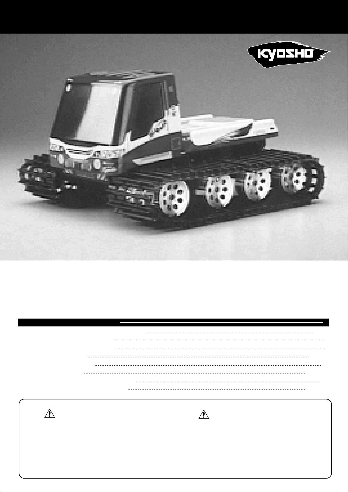
1 / 12 SCALE RADIO CONTROLLED .10 ENGINE POWERED QRC SERIES
NITRO BLIZZARD
ニトロブリザード
目次 Index Inhaltsverzeichnis
●キットの他にそろえる物 Required for operation
●プロポの準備Radio preparation
●組立て前の注意 Before you begin
●本体の組立て Assembly
●メンテナンス Maintenance
●分解図 Exploded View
●取扱いの注意 Operating your model safely
●パーツリスト Spare parts & optional parts
2 ~ 3
5 ~18
19
20 ~ 21
22
23 ~ 24
3
4
安全のための注意事項
この無線操縦模型は玩具ではありません!
●この商品は高い性能を発揮するように設計されています。組立てに不慣れな方
は、模型を良く知っている人にアドバイスを受け確実に組立ててください。
●小さい部品があるので、組立て作業は幼児の手がとどかない所で必ずおこなっ
てください。
●動かして楽しむ場所は、万一の事故を考えて安全を確認してから、責任をもっ
てお楽しみください。
●組立てた後も、説明書がいつでも見られるように大切に保管してください。
※製品改良のため、予告なく仕様を変更する場合があります。 Specifications are subject to change without prior notice!
© 1998 KYOSHO
●First-time builders should seek advice from people having building experience in order
to assemble the model correctly and to produce its performance to full extent.
●Assemble this kit only in places out of childrenÕs reach!
●Take enough safety precautions prior to operating this model. You are responsible for
this modelÕs assembly and safe operation!
●Always keep this instruction manual ready at hand for quick reference, even after
completing the assembly.
SAFETY PRECAUTIONS
This radio control model is not a toy!
No. 31851
Page 2
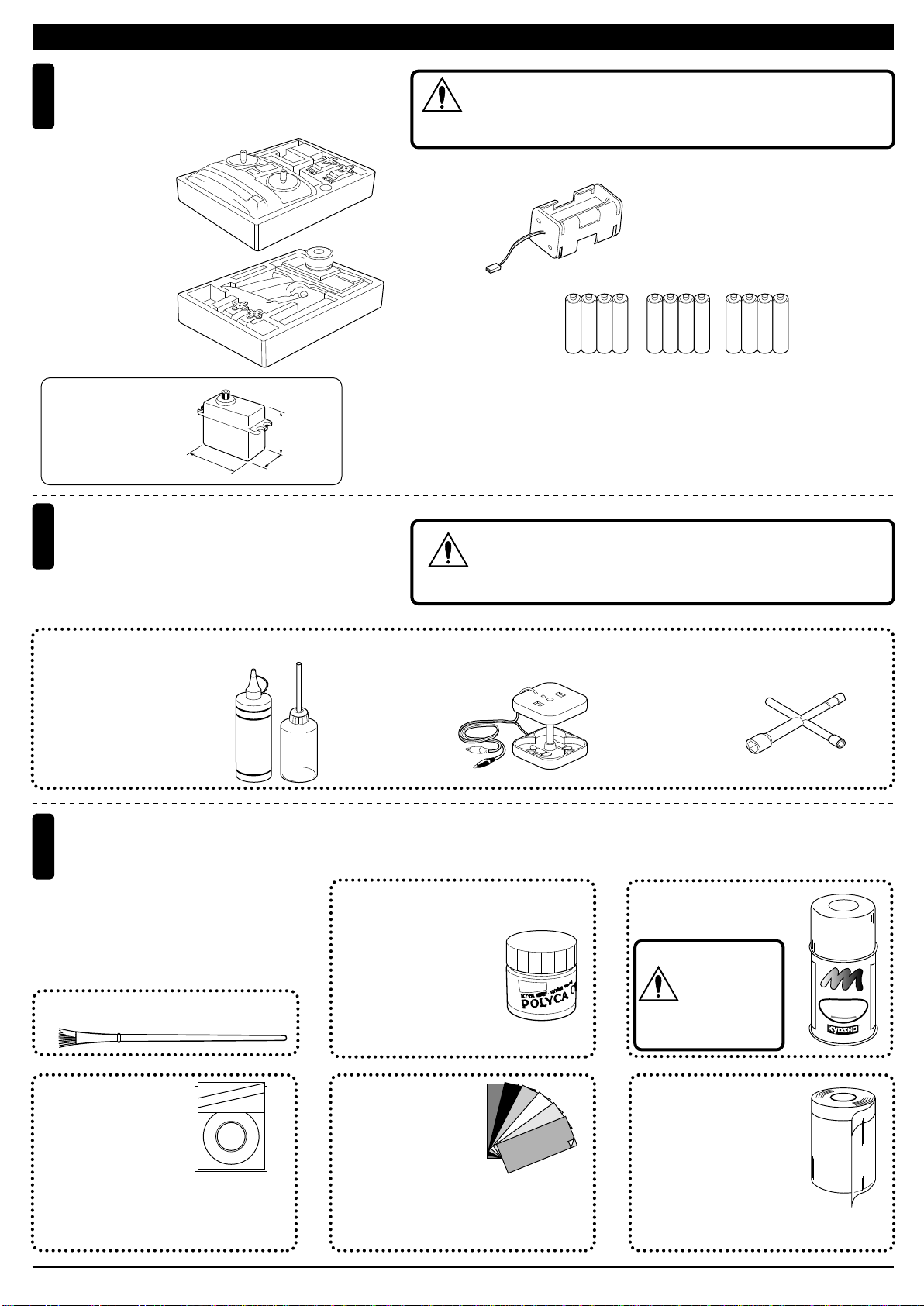
キットの他にそろえる物 / REQUIRED FOR OPERATION
2チャンネル2サーボ無線操縦機(プロポ)
Minimum 2 channel radio with 2 servos.
1
■スティックタイプ
Stick-type
■ハンドルタイプ
Wheel-type
使用できるサーボサイズ
Suitable servos
31~41mm
燃料と始動用具
2
Required for engine starting:
31~36mm
16~20mm
地上用(自動車用)のプロポ(2チャンネル2サーボ仕様)セットを
必ず使用してください。(地上用以外使用禁止)
CAUTION: Only use a surface radio with 2 channels and 2 servos!
注意
■電池ボックス
Battery Box
・ プロポセットに付いているときは必要ありません。
・ If already included with the radio, no battery box needs to
be purchased separately.
■単3乾電池
AA-size Batteries
AAAA
●プロポの取扱いは、プロポに付属の説明書を参考にしてください。
● For more information on the radio, refer to its instruction manual.
AAAA AAAA
ガソリンや灯油は使用禁止
WARNING: Never use gasoline and kerosene!
警告
No.73301 スターターパック
●エンジン始動に必要な用具セット
■グロー燃料、燃料ポンプ
Glow Fuel & Fuel Pump
HANDY
FUEL
塗料(ボディ塗装用)
Paints (for painting the body shell)
3
●ボディの塗装には塗料が必要です。京商では、
モデル用塗料、スプレーを用意していますの
でご利用ください。
For painting the body, use Kyosho paints for
models!
■筆
PAINT BRUSH
ape
No.1841
1842
1843
1859
1860
(1mm x 5m)
(1.5mm x 5m)
(2.5mm x 5m)
(0.4mm x 8m)
(0.7mm x 8m)
ミクロンラインテープ
MICRON LINE TAPE
マスキング、細部デザイ
ン用伸縮自在テープです。
Super-flexible tape for
masking and detail designing jobs.
T
ne
Li
cron
i
M
KYOSHO
■ブースターコード
Booster Cord
No.2230
ポリカカラー
(筆ぬり塗料)
POLYCA COLOR
(Brush paints)
No.96701
D‑フレックスカラーデカール
D FLEX COLOR DECAL
伸縮自在の特殊素材で3次曲面
にもきれいに貼れる粘着シートです。
Self-adhesive super-flexible sheets that
bond to polycarbonate - even when
applied to curved surfaces.
■プラグレンチ
Plug Wrench
No.76301〜76711
京商スプレーカラー
KYOSHO SPRAY COLOR
スプレーカラーを
使用する場合、缶
の説明を良く読ん
でください。
CAUTION: Before
注意
using spray colors,
always read their
explanations!
No.1947
マスキングカバーシート
MASKING SHEET
マスキングテープとビニール
シートが一体になった広範囲
マスク用テープです。
For safe masking jobs, use this plastic masking sheet featuring one self-adhesive edge.
F
U
N
E
L
P
I
R
A
O
F
P
F
T
K
O
Y
H
S
O
S
P
R
O
R
L
A
O
Y
C
R
2
Page 3
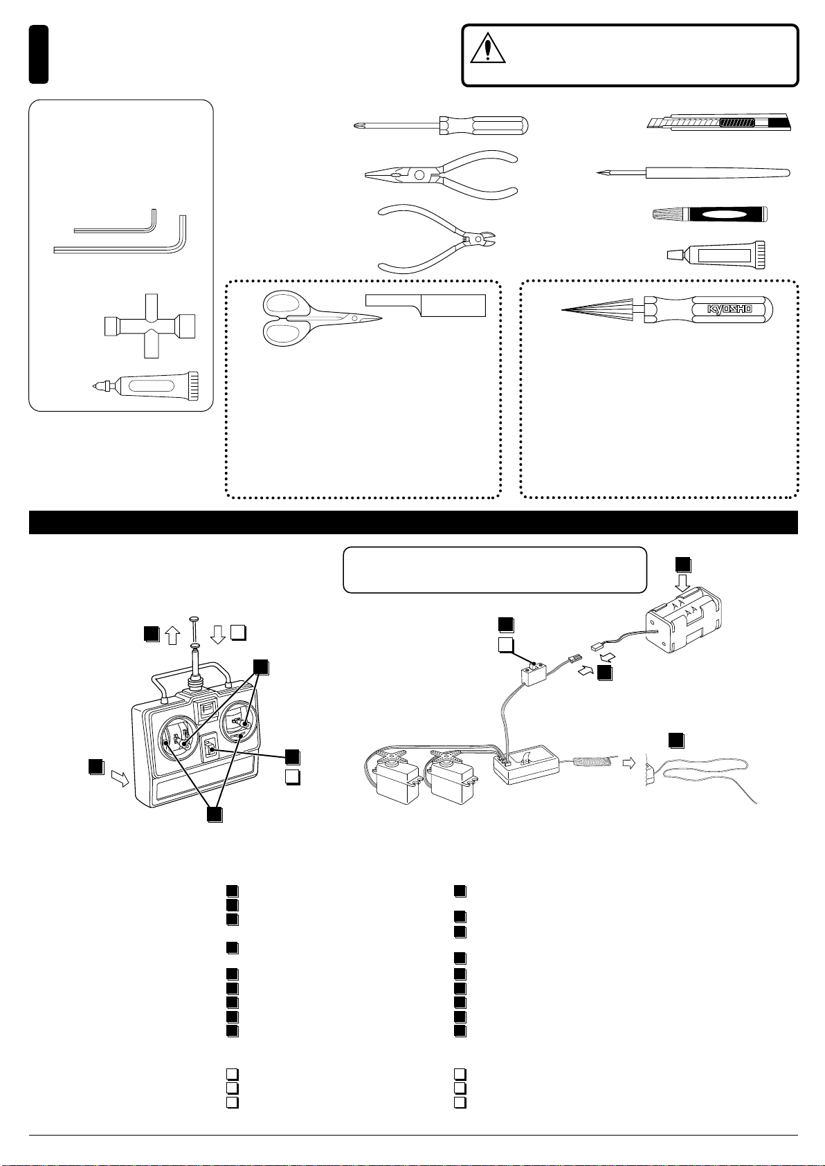
組立てに必要な工具
Tools required
4
使用する工具の取扱いには、充分注意してください。
CAUTION: Handle tools carefully!
注意
キットに入っている工具
TOOLS INCLUDED
■六角レンチ(1.5mm, 2mm)
Hex Wrench (1.5mm, 2mm)
■十字レンチ
Cross Wrench
KreuzschlŸssel
Cl en croix
■グリス
Grease
Fett
Graisse
GREASE
■+ドライバー(大、中、小)
Phillips Screw Driver (l, m, s)
■ラジオペンチ
Needle Nose Pliers
■ニッパー
Wire Cutters
ラウンドカッター&サンダー
ROUND CUTTER & SANDER
ボディのカット、仕上げ用。曲線部分も楽に作業が
できます。
For trimming bodies. Cutting along curved lines
never was so easy!
No.1829
■カッターナイフ
Sharp Hobby Knife
■キリ
Awl
■瞬間接着剤
Instant Glue
■ゴム系接着剤
Rubber Cement
ゴム系接着剤
スペシャルテーパーリーマー
SPECIAL TAPER REAMER
No.80311
下穴加工が不要で、直接1 ~ 15mmの穴あけができる
工具です。
No need to pre-drill!
Drills neat 1 ~ 15mm holes directly!
プロポの準備 / RADIO PREPARATION
●プロポを下の順番にしたがってセットします。
Set up the radio as explained below.
2
1
12
9
ON
7
11
OFF
▲送信機
6
Transmitter
●始める時
1
送信機に単3乾電池をセットする。
2
送信機のアンテナをのばす。
3
電池ボックスに単3乾電池をセット
する。
電池ボックスのコネクターをつなぐ。
4
受信機のアンテナをのばす。
5
トリムを中央にセットする。
6
送信機のスイッチを入れる。
7
受信機のスイッチを入れる。
8
スティックを動かしてサ ーボ が動
9
いているか確認。
●終わる時
受信機のスイッチを切る。
10
11
送信機のスイッチを切る。
12
送信機のアンテナを縮める。
※ステアリング・スロットル共にリバーススイッチをノーマル側に
セットしてください。
Use the normal switch for both the steering and the throttle.
ON
8
10
OFF
4
▲スイッチ
Switch
▲受信機
▲サーボ
Servo
Receiver
●START
1
Insert the AA-size dry batteries into
the transmitter.
2
Extend the transmitter antenna.
3
Insert the AA-size dry batteries into
the battery box.
4
Plug in the battery box.
Unwind the receiver antenna.
5
Center the trims.
6
Switch on the transmitter.
7
Switch on the receiver.
8
9
Make sure the servos move according
to your transmitter inputs.
●FINISH
Switch off the receiver.
10
11
Switch off the transmitter.
12
Retract the transmitter antenna.
3
▲電池ボックス
Battery Box
5
3
Page 4
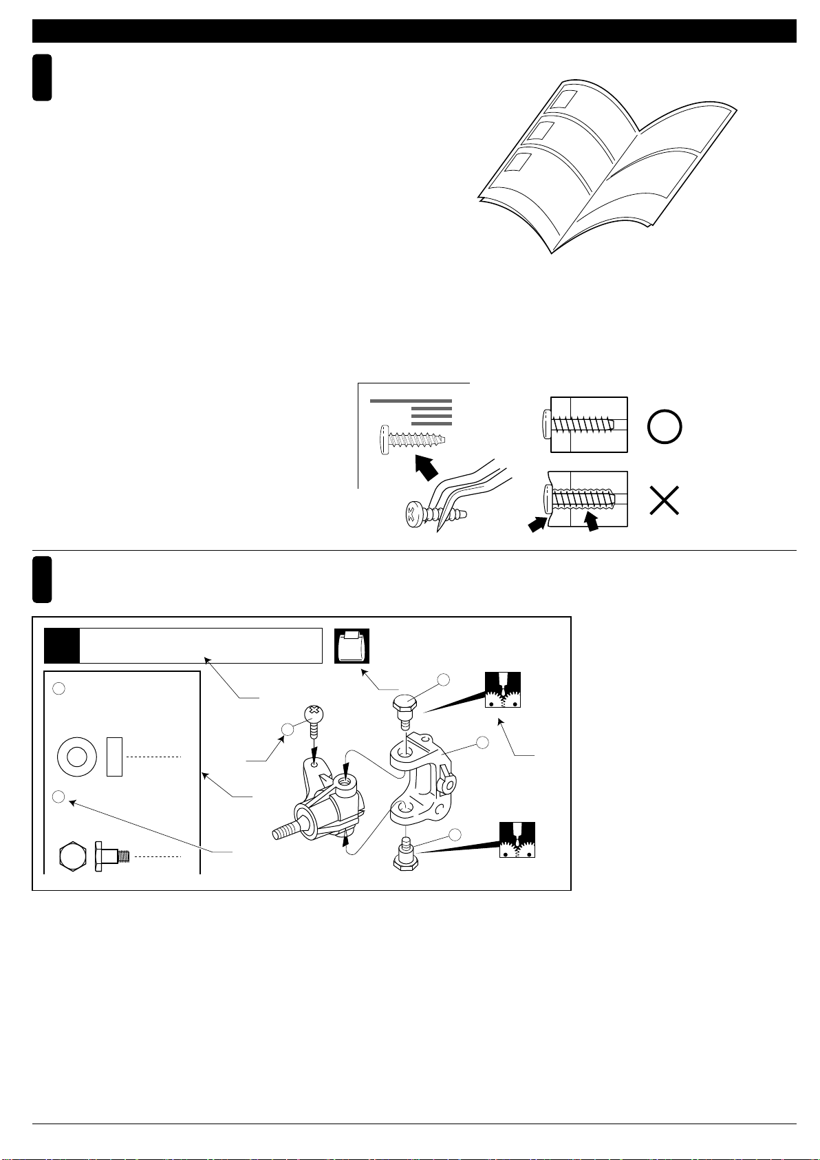
組立て前の注意/BEFORE YOU BEGIN
組立ての前に下記のことに注意してください。
1
●この説明書を良く読み、構造を理解する。
●キットの内容を確かめる。
※万一不良、不足がありましたら、お買い求めの販売店か、当社「ユーザー
相談室」までご連絡ください。
●小さな部品の形やサイズを間違えないようにする。図を参考にして確
認しながら組立てる。
●TPビス締めるときは・・・
締めこみが固くても部品が固定されるまで締めてください。
ただし、部品が変形するまで締めるとビスがきかなくなります。
Before assembling, please read the following carefully:
●First, read this instruction manual and understand the modelÕs con-struction.
●Check the contents of this kit.
Should parts be missing, immediately contact the retail shop or your nearest
Kyosho distributor.
●Do not take the wrong screw or small part. Compare it to the true-toscale dia-gram in each assembly step, then install it.
●When tightening a self-tapping (TP) screw:
Even if feeling hard, tighten a TP screw until the part will be securely attached.
However, do not overtighten it as the plastic thread inside the part may strip!
Correct
説明書の見かた
2
How to read the instruction manual:
フロントサスペンション
Front Suspension
1
4
5 x 10mm
キングピン
5
King Pin
メタル
Metal Bushing
Wrong
〔説明例Example〕
No.4, No.5, No.6
A
6
4
C
D
5
7
D
B
C
4
5
A: この項目で組立てるおおよその場所。
B: 小物部品の名前、原寸図、使用数。
C: キット内の部品は、ビス類を除いてキー
No.が付けられています。スペアパーツを
購入する時はキーNo.を参照して下さい。
D: 説明書内では多くのマークが使用されて
います。マークに注意して組立てを進め
てください。マークの説明は、各ページ
の下にあります。
4
A: Indicates the number of the assembly step and
the part that will be assembled.
B: Key Number, Part Name, True-to-scale
Diagram, Quantity Used.
C: All parts except screws are identified by key
numbers. For purchasing spare parts, find the
key number of the part needed in the spare
parts list and refer to the left column to look up
the corresponding order number.
D: This instruction manual uses several symbols.
Please note them during the entire assembly at
the bottom of each page.
Page 5
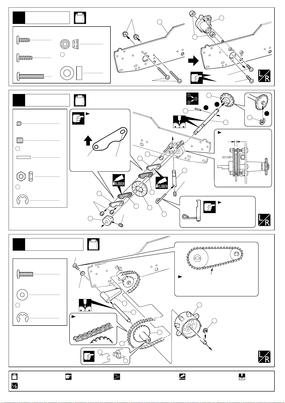
1
ブレーキ
Brake
No.1, No.2
3mm
1
3
3x8mm
TPビス
TP Screw
3x10mm
TP Screw
3x18mm
Screw
TPビス
ビス
ブレーキ
Brake
2
3 x 3mm
Set Screw
4 x 4mm
Set Screw
13
3mm
Nylon Nut (Thin)
12
セットビス
セットビス
2 x 10mm
Pin
E4.0
E-ring
ピン
ナイロンナット(薄)
Eリング
3mm
フランジナット
Flanged Nut
2
2
5x10mm
2
Metal Bushing
4
2
上
Top
2
2
4
2
4
メタル
4
No.2, No.6
向きに注意。
Note the direction.
長穴丸穴
Elongated HoleRound Hole
5
3mm
4
4x4mm
3x18mm
5
6
2
3x8mm
3x10mm
14
2
13
1
3
12
11
上から見た図
Top View
約1.5mm
approx. 1.5mm
8
9
3x3mm
左側
Left
6
向きに注意。
7
Note the direction.
10
フロントアーム
Front Arm
3
3 x 10mm
Screw
3mm
Washer
12
E4.0
E-ring
使用する袋詰。
Part bags used.
左右同じように組立てる。
Assemble left and right sides the same way.
ビス
2
ワッシャー
2
Eリング
2
No.2, No.3, No.6
3x10mm
3mm
チェーンの向き注意。
Note the direction.
17
注意して組立てる所。
Pay close attention here!
15
16
17
18
19
番号の順に組立てる。
Assemble in the specified order.
チェーンが上下に大きく振れずスムーズに
駆動するよう張り調整する。
Adjust the chain to move smoothly.
19
12
ゴム系接着剤で接着する。
Apply instant glue (CA glue, super glue).
グリスを塗る。
Apply grease.
5
Page 6
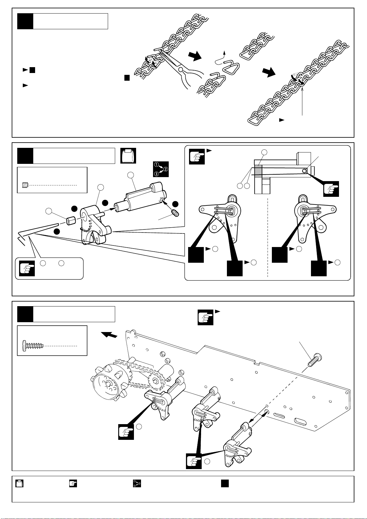
チェーンの調整
Chain Adjustment
4
●使用しはじめの時、長期間使用した時にチェーン
がたるみます。チェーンがたるんだ時は...
The new chain get loose after several runs.
3のチェーン張り調整をおこなう。
When the chain get loose, adjust again like 3 .
チェーンの張り調整で調整しきれない時は、図の方法で
チェーンのコマをつめる。
When it is too much loose to adjust, take off
the one piece of chain as drawing.
つないで元にもどす。
Connect together and back
to the original shape.
サスペンション
Suspension
5
3 x 3mm
Set Screw
セットビス
22
3
20 21
太 細
Thick Thin
サスペンション
Suspension
6
3 x 10mm
TP Screw
TPビス
No.3
向きに注意。
Note the direction.
22
3x3mm
24
6
2
23
1
3x3mm
4
20
太
Thick
x1
6
前
Front
202121
細
Thin
x2
左右対象に組立てる。
Assemble left and right
sides the same way.
<左 Left>
x1
20
太
Thick
3x10mm
x2
21
細
Thin
使用する袋詰。
Part bags used.
6
注意して組立てる所。
Pay close attention here!
20
太
Thick
番号の順に組立てる。
Assemble in the specified order.
21
細
Thin
2セット組立てる(例)。
x2
Assemble as many times as specified.
Page 7
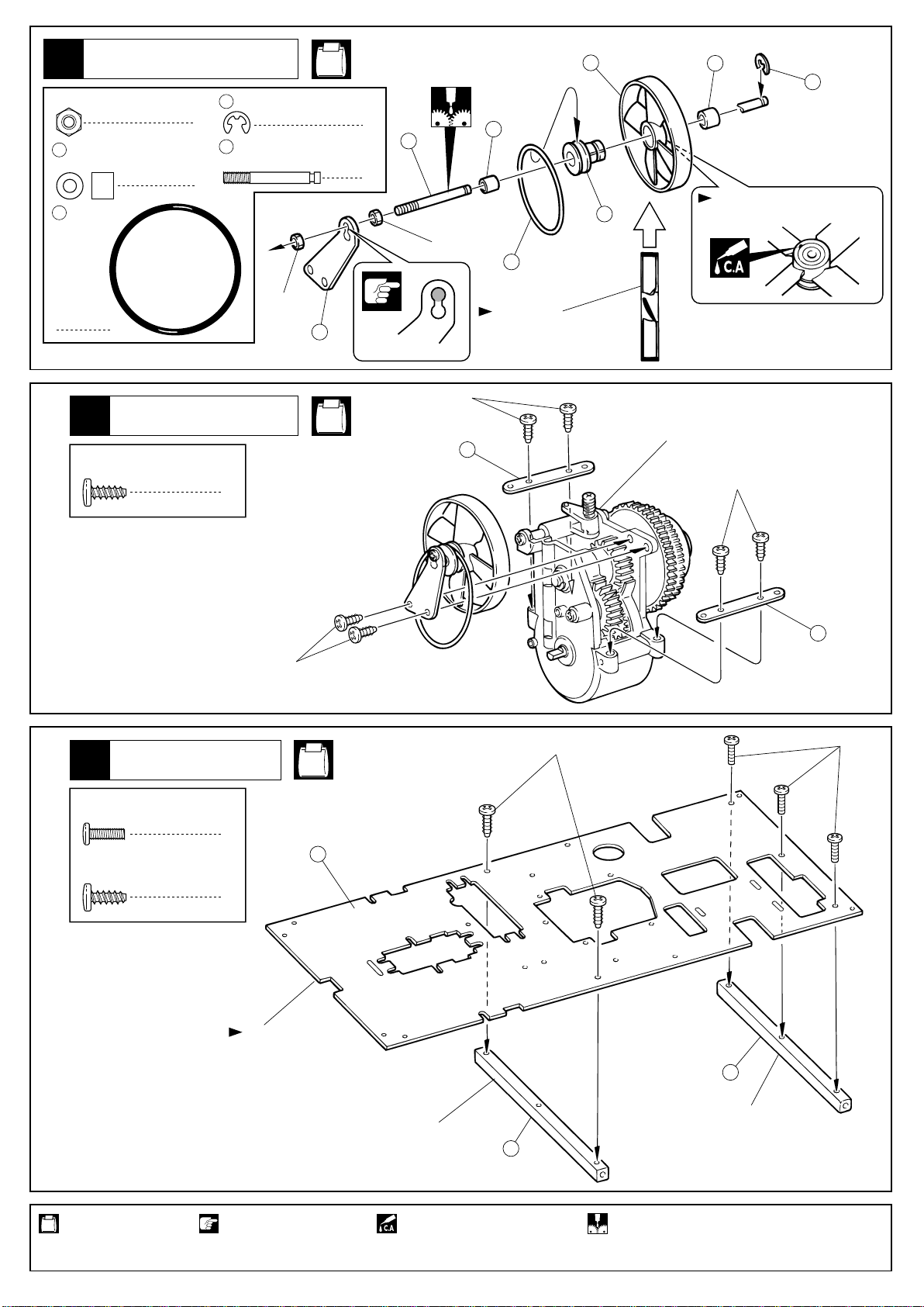
クーリングファン
Cooling Fan
7
3mm
Nut
27
28
ナット
3x6x5mm
Metal Bushing
Oリング
O-ring
メタル
2
2
31
E2.5
E-ring
26
ファンシャフト
Fan Shaft
Eリング
No.3, No.6
1
26
1
3mm
27
28
30
29
27
31
穴に瞬間接着剤を流す。
Put instant glue into the hole.
1
QRCユニット
QRC Unit
8
3 x 8mm
TP Screw
TPビス
シャシー
Chassis
9
6
3mm
3x8mm
25
No.1, No.4
No.3
3x8mm
向きに注意。
Note the direction.
32
3x8mm
QRCユニット
QRC Unit
3x8mm
32
2.6x8mm
2.6 x 8mm
Screw
3 x 8mm
TP Screw
使用する袋詰。
Part bags used.
ビス
TPビス
3
33
2
向きに注意。
Note the direction.
注意して組立てる所。
Pay close attention here!
黒(プラ)
Black (Plastic)
瞬間接着剤で接着する。
Apply instant glue (CA glue,
35
34
銀色(アルミ)
Silver (Aluminum)
グリスを塗る。
Apply grease.
7
Page 8

10
QRCユニット
QRC Unit
No.4
3 x 15mm
Screw
3mm
Nut
36
プラカラー
Plastic Collar
ビス
ナット
エンジン
Engine
11
2.6 x 25mm
Screw
ビス
39
4
8
4
3x15mm
36
3mm
3mm
3mm
x4
38
No.4
図の角度になるよう
2
にビスで調整する。
Adjust the angle as
shown in the picture
by screw.
15°
30で使用。
To be use 30 .
39
185mm
37
2.6x25mm
185mm 50mm
エンジン
Engine
12
エンジン取付け後、ミッション本体とエンジンが平行に取付けられている事を必ず確認
してください。平行に取付けられていない場合、ローギヤ及びハイギヤのバックラッシ
ュが合わずトラブルの原因となります。
Confirm the transmission unit and engine are parallel. If both are not parallel,
the backlash of the lower and upper gear will be either too tight or too loose,
resulting in damages for the engine and transmission unit !
クラッチベルと2スピードトランスミッション
が異音なくスムーズに回転するよう注意する。
Adjust the clutch bell and 2 speed transmission
to rotate smoothly without any noise.
平行
Parallel
3 x 8mm
Screw
ビス
クラッチベル
3
Clutch Bell
2スピードトランスミッション
2-Speed Transmission
フライホイール
Flywheel
エンジンユニット
Engine Unit
3x8mm
3x8mm
使用する袋詰。
Part bags used.
8
注意して組立てる所。
Pay close attention here!
4セット組立てる(例)。
x4
Assemble as many times as specified.
Page 9

燃料タンク
Fuel Tank
13
3x8mm
TPビス
TP Screw
3x10mm
TP Screw
TPビス
3x8mm
4
40
1
No.4
40
41
42
シリコンチューブ
44
Silicone Tube
95mm55mm
0 50 100 130mm
125mm
3x8mm
41
44
3x10mm
95mm
43
44
OUT
IN
55mm
44
44
44
125mm
125mm
55mm
3x8mm
44
55mm
3x8mm
44
125mm
スロットルリンケージ
Throttle Linkages
14
3 x 8mm
TP Screw
47
TPビス
Oリング
O-ring
スロットルリンケージ
Throttle Linkages
15
3 x 8mm
TP Screw
50
TPビス
ロッド
Rod
No.5, No.6
47
45
2
46
1
3x8mm
3x8mm
No.5, No.6
3x8mm
48
1
50
49
使用する袋詰。
Part bags used.
原寸図
True-to-scale diagram.
1
をカットする。
Cut off shaded portion.
50
63mm
グリスを塗る。 可動するように組立てる。
Apply grease.
Ensure smooth non-binding movement while assembling.
注意して組立てる所。
Pay close attention here!
9
Page 10

16
プロポ
Radio
3x15mm
No.5
3 x 15mm
TP Screw
TPビス
プロポ
Radio
17
3 x 15mm
TP Screw
TPビス
3x15mm
スロットルサーボ
4
Throttle Servo
52
51
51
52
52
No.5
52
4
スロットルリンケージ
Throttle Linkages
18
2 x 6mm
Screw
3 x 3mm
Set Screw
56
57
55
ビス
セットビス
リンケージストッパー(金)
Linkages Stopper (gold)
2 x 6 x 5mm
Stopper
ロッド
Rod
ストッパー
53
サーボの向きに注意。
Note the direction.
ステアリングサーボ
Steering Servo
54
3x15mm
3x15mm
No.5
1
3x3mm
1
1
2x6mm
57
1
曲げる。
Bend.
55
10
使用する袋詰。
Part bags used.
1
をカットする。
Cut off shaded portion.
(金)
56
(gold)
注意して組立てる所。
Pay close attention here!
55
仮止め。
Tentatively tighten.
100mm
25mm
別購入品
Must be purchased separately!
Page 11

スロットルリンケージ
Throttle Linkages
19
3 x 3mm
Set Screw
2 x 8mm
TP Screw
57
セットビス
TPビス
2 x 6 x 5mm
Stopper
ストッパー
2
1
2
16 ~ 19mm
平行
Parallel
No.5
16 ~
19mm
58
57
3x3mm
3
2
3x3mm
58
1
57
2x8mm
QRCリンケージ
QRC Linkages
20
3 x 3mm
Set Screw
57
50
セットビス
2 x 6 x 5mm
Stopper
ロッド
Rod
50
52mm 12mm
プロポ
Radio
21
3 x 8mm
TP Screw
TPビス
ストッパー
No.5
1
1
3x3mm
1
57
3
2
50
1
曲げる。
Bend.
No.4, No.5
60
3
62
61
59
54
プロポの説明書を参考に、
コネクターを接続する。
Connect as per radio
instruction manual.
コードをストラップで束ねる。
Bind the wires with strap.
63
64
使用する袋詰。
Part bags used.
可動するように組立てる。
Ensure smooth non-binding movement while assembling.
番号の順に組立てる。 をカットする。
Assemble in the specified order. Cut off shaded portion.
3x8mm
3x8mm
注意して組立てる所。
Pay close attention here!
20mm残しカットする。
Cut the strap with allowance
of 20cm as shown
in the picture.
62
30mm
両面テープ
59
Double-sided Tape
別購入品
Must be purchased separately!
11
Page 12

スロットルリンケージ
Throttle Linkage
22
前進
Forward
3mm
3mm
2
セットビス
Set Screw
3
ニュートラル
Neutral
A A
後退
Reverse
1
3
1mm
プロポのスイッチを入れ = になっていることを
1
確認する。ずれていたら、トリムレバーで調整する。
図の位置でセットビスをしめる。
2
キャブレターの穴のすきまが最スロー1mmになる位置
3
でビスをしめる。
ロールバー
Roll Bar
23
3 x 3mm
Set Screw
3 x 8mm
Screw
セットビス
ビス
A A
Switch on the radio and make sure both gaps are equal. If not equal, correct with the throttle trim.
1
Tighten both set screws when both gaps are 3mm.
2
Tighten the set screw ensuring the carburator is 1mm at idle.
3
A
68
No.5
65
67
54
2
2
66
3x3mm
2
1
3
66
3x3mm
3x8mm
デフギヤ
Gear Differential
24
2 x 8mm
TP Screw
74
8 x 10mm
Collar
69
3 x 20mm
Shaft
使用する袋詰。
Part bags used.
12
TPビス
カラー
シャフト
No.6
73
72
4
74
74
73
2
71
1
2x8mm
2x8mm
グリスを塗る。
Apply grease.
72
71
70
番号の順に組立てる。
Assemble in the specified order.
69
70
余分をカットする。
Cut off excess.
Page 13

ギヤボックス
Gearbox
25
3 x 10mm
TPビス(銀)
TP Screw (silver)
75
10 x 14mm
Metal Bushing
2 5 x 10mm
Metal Bushing
5mm
Washer
12
E4.0
E-ring
メタル
メタル
ワッシャー
Eリング
No.6
79
80
6
79
77
80
2
80
2
2
79
75
5mm
80
75
5mm
78
77
デフギヤ
Gear Differential
76
4
3x10mm
2
2
3x10mm
12
1
シャシー
Chassis
26
3 x 8mm
TP Screw
3 x 8mm
Screw
Front
TPビス
ビス
向きに注意!
Note the direction!
前
前
Front
No.4, No.5, No.6
3x8mm
8
2
3x8mm(TP)
3x8mm(TP)
62
1
2
77
2
35
3x8mm(TP)
62
<左 Left>
3x8mm
使用する袋詰。
Part bags used.
3x8mm(TP)
3x8mm(TP)
番号の順に組立てる。
Assemble in the specified order.
3x8mm(TP)
<右 Right>
注意して組立てる所。
Pay close attention here!
13
Page 14

ステアリングリンケージ
Steering Linkages
27
3 x 3mm
Set Screw
2 x 8mm
TP Screw
103
57
81
83
セットビス
TPビス
プラテーパーワッシャー
Plastic Tapered Washer
2 x 6 x5mmストッパー
Stopper
4.8mm
ボール
Ball
ロッド (C)
Rod (C)
82
、でブレーキのきき具合(車体の曲がり具合)を調整する。
No.5,
No.7
2
2
2
2
向きに注意。
Note the direction.
57
Adjust the strength of brake (in other words, equalize the
brake strength of both right and left) with 57 and 82 .
ブレーキのききすぎに注意。
Do not brake too hard.
10
103
3x3mm
84
57
3x3mm
57
84
103
約140mm
approx. 140mm
2x8mm
82
81
83 8257
平行
Parallel
8~10mm
8~10mm
83
2
2
ステアリングサーボ
Steering Servo
シャシー
Chassis
28
3 x 8mm
TP Screw
3 x 10mm
TP Screw
TPビス
TPビス
リヤサスペンション
Rear Suspension
29
86
3 x 6 x5mmストッパー
Stopper
No.4, No.7
88
87
10
85
1
3x8mm
3x8mm
2
3x8mm
64
1
3x8mm
No.2, No.5, No.7
4
3x8mm
2
3x10mm
86
103
約1mm approx. 1mm
約60mm
approx. 60mm
94869293
95
5.8mm
96
103
3x10mm
Screw
使用する袋詰。
Part bags used.
ピロボール
Pillow Ball
プラテーパーワッシャー
Plastic Tapered Washer
ビス
別購入品
Must be purchased separately!
14
3x15mm
TP Screw
2
3 x 3mm
Set Screw
2
3mm
フランジナット
Flanged Nut
2
TPビス
2
93
4
2
Oリング
O-ring
12
E4.0
E-ring
Eリング
セットビス
可動するように組立てる。
Ensure smooth non-binding movement while assembling.
番号の順に組立てる。
Assemble in the specified order.
4
2
89
3x10mm
12
90
をカットする。
Cut off shaded portion.
3mm
91
93
86
103
3x3mm
3x15mm
左右同じように組立てる。
Assemble left and right sides the same way.
92
86
3x3mm
94
95
96
Page 15

30
97
Oリング
O-ring
サブマフラー
Sub Muffler
No.4, No.7
デカール『QRC保護用』
Protect Seal for QRC.
39
3mm
93
112
3x45mm
111
97
93
112
111
1
93
Oリング
O-ring
3mm
ナイロンナット
Nylon Nut
3 x 45mm
31
2x8mm
TP F/H Screw
ビス
Screw
ベルト
Belt
TPサラビス
201
24
93
90
2
1
1
39
50mm
No.8
2x8mm
201
2x8mm
ベルト
Belt
32
102
ホイルビス
Wheel Screw
4 x 8mm
101
Plastic Bushing
プラスチックブッシュ
12
x2
No.6, No.9
6
100
101
101
102
取付位置。
Use this hole.
使用する袋詰。
Part bags used.
2セット組立てる(例)。
x2
Assemble as many times as specified.
左右同じように組立てる。
Assemble left and right sides the same way.
グリスを塗る。
Apply grease.
可動するように組立てる。
Ensure smooth non-binding movement while assembling.
15
Page 16

ベルト
Belt
33
3x10mmビスでベルトの
張り調整をする。
Adjust belts by 3x10 mm
size screws.
上下に大きく振れない
程度に張る。
Check the tension of belts.
No.9
3x10mm
64
102 101
ホイルビス
Wheel Screw
2
シャシー
Chassis
34
3 x 8mm
TP Screw
TPビス
4 x 8mm
Bushing
6
ブッシュ
101
4
100
101
102
3x8mm3x8mm
ベルトの張り調整後に
組立てる。
Assemble this tire after
checking tension of belts.
No.1
113
3x8mm
ボディマウント
Body Mounts
35
3 x 10mm
TP Screw
0 10 20mm
使用する袋詰。
Part bags used.
4セット組立てる(例)。
x4
Assemble as many times as specified.
TPビス
16
2
3x10mm
をカットする。
Cut off shaded portion.
No.7, No.9
104
15mm
左右同じように組立てる。
Assemble left and right sides the same way.
グリスを塗る。
Apply grease.
104
8mm
104
x24
8mm
15mm
104
105
3x10mm
8mm
15mm
104
瞬間接着剤で接着する。 ゴム系接着剤で接着する。
Apply instant glue (CA glue, super glue).
15mm
8mm
Rubber Cement.
x4
104
Page 17

36
37
ボディ
Body Shell
ボディ
Body Shell
106
6mm
6mm
6mm6mm
4mm
塗装
Painting
38
塗装前に、洗剤で油やよごれを洗う。
Before painting, use a neutral detergent to remove
any oil residues and dirt.
ウインドウ部分に、内側からマスキングシートを貼る。
Mask the windows from the inside.
京商スプレーカラーでボディ内側を塗装する。
Paint the body shell from the inside using
KyoshoÕs spray colors.
塗分けはパッケージ写真も参考にしてください。
Refer to the pictures on the box for the color scheme.
4mm
4mm
107
塗装後、ボディ表面の保護ビニールシート
をはがしておく。
After painting, remove the protective film
from the body shell.
使用する袋詰。
Part bags used.
をカットする。 6mmの穴をあける(例)。
Cut off shaded portion. Drill holes with the specified diameter.
6mm
17
Page 18

39
デカール
Decals
図の位置に から順にデカールをはる。
Apply the decals to the spots indicated in numerical order.
1
7
3
4
ナンバーのついていないデカールは好きな位置に貼る。
Decals with no number apply any place.
マジックテープ
Velcro
40
接着前に、洗剤で油や
よごれを洗う。
Clean-up surface
before applying.
No.9
1
5
2
6
108
109
50mm
109
41
110
フックピン
Hook Pin
ボディ
Body Shell
108
位置を合わせて貼る。
108
Check the position before applying.
110
4
5
2
2
2
109
4
1
110
3
3
使用する袋詰。
Part bags used.
注意して組立てる所。
Pay close attention here!
18
をカットする。
Cut off shaded portion.
番号の順に組立てる。
Assemble in the specified order.
左右同じように組立てる。
Assemble left and right sides the same way.
Page 19

2スピードトランスミッション ADJUSTMENT OF THE GEAR SHIFT TIMING
シフトタイミングの調整時は、安全のため必ずエンジンを止めて行なってください。
For reasons of safety, do not perform adjustments while the engine is running!
1
シフトタイミングの調整の前に、エンジンの調整を充分に行ってください。エンジン調整は、3x3mmセットビスを締め込み、シフトアップし
ないようにし、走行させながら行ってください。
エンジンの調整方法は、使用するエンジンの説明書に従ってください。
Adjust the engine before adjusting the gear shift timing. For adjust-ing the engine, run the engine with the 3 x 3mm set screw tightened to
make sure the engine does not shift up. Adjust the engine as per engine instruction manual.
エンジンの調整が終了したら、次にシフトタイミングの調整を行ないま
2
す。走行場所に合わせて3x3mmセットビスでシフトタイミングを調整し
ます。締め込むとシフトアップのタイミングが遅くなり、ゆるめるとタ
イミングが速くなります。
実際に車を走行させながらシフトタイミングの調整ビスを半回転ずつ緩
めていきます。
走行場所にマッチングする様になるまで、この作業を繰り返し行なって
ください。
Once the engine adjustment is completed, proceed to the adjustment of
the gear shift timing.
Adjust the gear shift timing to your engine and the track with the 3 x 3mm
set screw. As you tighten the 3 x 3mm set screw, the shift timing
becomes slow, and as you unscrew it, the shift timing becomes quick.
Adjust the timing by unscrewing the 3 x 3mm set screw by half turns
actually while running the car. Match the timing to the specific track
conditions.
1.5mm六角レンチ
Hex Wrench (1.5)
シフトタイミングが遅くなる。
Shift timing becomes slower.
シフトタイミングが早くなる。
Shift timing becomes quicker.
3
シフトアップのタイミングは、エンジンの最高回転数の 約 80%程度でシフトアップする様に調整すると、最も効率良く使用する事ができます。
Set the timing so the gears shift up when 80% of total rpm are reached. This type of setting will allow you to make a better use of your engine.
シフトタイミング調整ビスの締め込み過ぎは、シフトスプリングの破損の原因になるので注意してください。
4
If overtightening the 3 x 3mm set screw, you may damage the shift spring!
メンテナンス MAINTENANCE
2スピードトランスミッション は、高速で回転するため下記の点に注意してメンテナンスを行ってください。
●各回転部のベアリングなどは、スムーズに回転するように注油をしてください。
●シャシーにビスのゆるみがないか定期的に点検し、増し締めしてください。
●ワンウエイベアリングがロック方向でロックするか定期的に点検し、ロックしない場合は、シャフト及び、ワンウエイベアリングを交換して
ください。
●ギヤのごみや小石は、破損の原因になるので常にきれいにしておきましょう。
Note the following in order to ensure smooth operation and long life of the 2-Speed Transmission.
● Lubricate the ball bearings to ensure smooth operation.
● Regularly check whether the screws on the chassis are firmly tightened, and retighten if necessary.
● Regularly check whether the oneway bearing locks into the direction indicated. If it does not lock, replace the shaft or oneway bearing.
● Keep the gears clean from dirt and sand to prevent damage.
走行上の注意
Safety Precautions
●走行時は、必ずボディを装着してください。
●必要以上に前/後進の操作を繰り返すことは、おやめください。
●
下記の場所での走行は、故障の原因になりますのでおやめください。
・段差などで前/後進出来ない状態での走行。
・重量物を載せての走行。
・エンジンを高回転にしての走行。
・急登坂、降坂を類繁に行なう走行。
・泥池、水たまり走行。
●雪上での使用時は、受信機等に防水対策を十分行ってください。
●毎走行後汚れや雪、水分を取り除いてください。
●定期的に、各部のビス類が緩んでいないか、
部品に異常がないか確認してください。。
●走行毎に、
確認してください。
●坂道、段差などベルトが駆動しているときは、前/後進が切り
替わりにくくなる場合がありますが、故障ではありません。
●標準エンジン以外のエンジンの使用は、ギヤ等の破損の原因に
なりますのでおやめください。
QRC/スロットルリンケージがスムースに動作するか
●Always run your car with the body shell mounted!
●Avoid changing the running direction too often and too abruptly.
●Do not run your car on ground:
・Can not run front and reverse between too big gap.
・Load heavy weigh.
・Run the engine high revolution.
・Climb and down sharp slope too may offen.
・Muddy and pudle condition.
●Receiver need water proof when drive on the snow.
●Clean-up model every time after running .
●Check screws and parts constantly.
●Ensure the throttle and QRC linkages move smoothly without binding.
●It may happen that changing the running direction is difficult espe-
cially when driving up a steep way or running on bumpy ground.
This, however, does not indicate any trouble.
●The gearing etc. may be damaged if you do not use the engine
supplied or an .10 class engine.
19
Page 20

EXPLODED VIEW
一部パーツ販売していないパーツがあります。
Note that some parts are not sold as spare parts!
151
67
39645-02
FZ-10
74381
79
BL-20
150
2 1916
80
77
1918
85
BL-4
96425
BL-11
FZ-13
6591
37
A
38
39305-07
39305-01
1384
75
74
73
OT28
12
BL-7
71
140
FZ-13
B
149
132
130
134
39305-07
1384
69
70
72
1918
FD-21
133
12
70
68
148
31
1382
2
131
71
74
BL-20
RM-11
GT-5
145
27
39305-02
1916
75
FZ-10
1387
136
2 1916
76
FZ-13
77
78
147
AB-15
30
138
39305-03
39431-04
137
39305-08
BL-20
77
BL-11
146
AB-17
39642
29
39305-01
139
80
144
143
28
39305-12
LD-70
27
39642-01
129
124
21916
142
26
92631-02
123
-06
92631-03
C
BL-5
113
92631-01
115
141
39642
25
92631-01
135
1901
2 1916
BL-11
12
1384
92631-02
119
40
12
1384
122
92631-02
E
91
118
117
116
92631-07
125
2 1916
57
BL-13
92631-05
127
92631-05
126
2 1916
128
92631-04
32
64
BL-4
FD-65
FD-29
44
FD-29
92631-02
2 1916
92631-02
123
-06
BL-16
H
55
D
121
FD-65
44
42
32
120
2 1916
92631-02
92801
BL-16
BL-6
BL-18
BL-18
96321
39
BL-19
92631-01
114
SPW-51
15
87
BL-11
56
BL-11
88
43
FD-65
BL-11
47
41
35
SPW-51
5
6
BL-7
BL-4
C
4BL-12
5
62
BV-11B
93
BL-12
FD-65
7
6
BL-13
16
17
BL-8
44
12
46
FD-29
OT-29
84
57
2
1916
1384
19
1705
BL-17
65
52
52
FD-65
FD-65
62
52
FD-65
53
BL-4
35
48
49
50
FD-65
57
58
45
F
57
FD-65
50
G
FD-65
51
FD-65
A
BL-17
66
57
F
G
E
39
BL-19
BL-11
112
103
111
FD-65
BL-11
97
BL-18
93
OT-29
BL-4
34
BL-11
36
D
82
FD-65
81
FD-65
83
60
61
FD-65
62
FD-65
BL-3
33
54
96441
59
1704
63
10
BL-12
8
BL-12
9
BL-19
104
110
EP-22
105
BL-11
BL-19
H
104
99
BL-10
BL-10
99
98
3 BL-6
2 1916
1 BL-2
LA-43
95
BL-6
101
100
BL-9
86
KC-18
90
101
102
BL-13
94
1284
103
86
96
BL-11
92
OT-29
93
24
BL-7
B
1384
BL-13
11
BL-13
13
BL-7
24
12
BL-7
14
BL-14
18
24
BL-7
22
22
23
23
101
BL-15
20
101
100
101
BL-9
102
100
BL-9
22
21
23
BL-15
101
21
101
100
BL-9
102
BL-15
101
102
BL-6
89
FD-65
KC-18
Page 21

取扱いの注意 / Operating your model safely / Zu Ihrer Sicherheit / Consignes de s curit
次のような時、場所では走らせない。思わぬ事故の原因になります。
WARNING: Do NOT operate the model in the following places and situations: (Non-observance may lead to accidents!)
VORSICHT: Bedienen Sie Ihr Modell niemals an folgenden Orten und unter folgenden UmstŠnden!
警告
ATTENTION: NÕoperez pas votre mod le dans les endroits suivants!
●走行させてはいけない場所。
1.自動車道路。
2.小さな子供のそば、人の多いところ。
3.民家の近く、公園など。
4.室内、せまいところ。
※人にケガをさせる原因になります。また、物をこわし
たり、他人の迷惑になります。
●プロポ関係の電池残量が少ない時。
電池が減ってくるとコントロールができなくなり、暴走
や衝突の原因なります。
●近くで無線操縦模型を楽しんでいる人がいる。
同じバンドでの同時走行はできません。コントロールが
できなくなり、暴走や衝突の原因なります。
●車の動きがおかしい??とき
すぐに走行を中止して原因を調べてください。原因不明の
まま走行させると、思わぬ故障や事故の原因になります。
Operate your model ONLY in spacious areas
with no people around! Do NOT operate it:
1. on roads!
2. in places where children and many people gather!
3. in residential districts and parks!
4. indoors and in limited space!
* Non-observance may account for personal injury and
property damage!
Always check the radio batteries!
With weak dry batteries, transmission and reception of
the radio fall off. You may lose control of your model
when operating it under such condition. This may also
lead to serious accidents!
Keep in mind that people around you may
also operate a radio control model!
NEVER share the same frequency with somebody else
at the same time! Signals will be mixed and you will
lose control of your model. This may lead to accidents!
When the model is behaving strangely . .!
Immediately stop the model and check the reason. As
long as the problem is not cleared, do NOT operate it!
This may lead to further trouble and unforeseen acci-dents!
Bedienen Sie Ihr Modell nur an sicheren und
gerŠumigen Orten. Bedienen Sie es niemals:
1. auf šffentlichen Stra§en!
2. dort, wo sich Leute und Kleinkinder aufhalten!
3. in Wohngebieten und Parks!
4. in engen, begrenzten Orten oder in RŠumen!
* Nichtbeachtung kann Verlet-zung von Personen sowie
SachschŠden zur Folge haben!
†berprŸfen Sie die Batterien der RC-Anlage!
Sobald die Batterien nachlassen, lassen auch das
Sende- und Empfangvermšgen nach. Die Bedienung
Ihres Modelles mit schwachen Batterien kann zum Ver-lust Ihres Modelles und schweren UnfŠllen fŸhren!
Bedenken Sie, da§ auch andere in Ihrer Umgebung
ein ferngesteuertes Modell bedienen kšnnten!
Stellen Sie sicher, da§ niemand zur selben Zeit die-selbe
Frequenz in Ihrer Umgebung benutzt! Das kann zum Ver-lust Ihres Model-les sowie zu schweren UnfŠllen fŸhren.
Wenn Ihr Modell nicht normal funktioniert, . . . :
Unterbrechen Sie die Bedienung augenblicklich und
untersuchen Sie die Ursache. Solange sie nicht geklŠrt
ist, bedienen Sie niemals Ihr Modell! Das kšnn-te
schwere UnfŠlle zur Folge haben!
01
05
Pour viter tout accident, nÕop rez votre mod le
jamais:
1. ˆ proximit de routes!
2. dans un endroit avec des enfants et promeneurs!
3. ˆ proximit de r sidences, dÕ coles et de hopitaux!
4. ˆ lÕint rieur ou dans un endroit troit!
* Toute non-observance pourrait entra”ner la perte de
votre mod le et avoir des cons quences fatales!
Quand les piles de la radio sont d charg es:
Si les piles sont insuffisamment charg es, lÕ mission et
la r ception de la radio deviennent faibles. LÕop ration
de votre mod le avec des piles insuffisamment charg es
pourrait entra”ner la perte de votre mod le ainsi que des
accidents graves!
Assurez-vous que personne nÕutilise votre fr quence au m me instant!
NÕop rez jamais sur la m me fr quence de quelquÕun
dÕautre. Cela pourrait entra”ner la perte de votre mod
le ainsi que des accidents graves!
Quand le fonctionnement de votre mod le est trange:
Arr tez imm diatement votre mod le et trouvez la cause.
Sinon, vous risquez la perte de votre mod le ainsi que
des accidents graves!
事故やケガ等の危険防止のため、次のことを必ずお守りください。
WARNING: In order to avoid accidents and personal injury, be sure to observe the following:
VORSICHT: Zur Unfall- und Sachschadenvermeidung, beachten Sie bitte auch folgendes:
警告
ATTENTION: Respectez les consignes suivantes afin de faire voluer votre mod le en toute s curit :
●燃料の取扱いの注意。
1. 取扱いは、必ず屋外で。
2. 模型用グロー燃料を必ず使用。
3. 火気には絶対に近づけない。
4. 飲んだり、目に入れたりしない。
5. 保管は、キャップをしっかり締め幼児の
手の届かない冷暗所に置く。
6. 使用後の空き缶は、火中に投げ入れない。
●回転している部分に、指や物などを入れない。
●走行直後は、エンジン、マフラー周辺は高温に
なっているので、すぐにはさわらない。
●Handling fuel safely:
1. Handle fuel only outdoors!
2. Only use glow fuel for radio control models!
3. Never use fuel indoors or in places with open fires
and sources of heat!
4. Never swallow fuel or let it into your eyes!
5. Store fuel only in cool, dry and dark places out of
children's reach! Tightly shut the cap!
6. Do not dispose of empty fuel cans into a fire! There
is danger of explosion!
●Do not put fingers or any objects inside rotat-
ing and moving parts!
●Right after use, do not touch the engine and
muffler! Danger of burning yourself!
22
禁止
PROHIBITED
VERBOTEN
DEFENDU
禁止
禁止
PROHIBITED
PROHIBITED
VERBOTEN
DEFENDU
●Zum sicheren Gebrauch von Kraftstoff:
1. Kraftstoff nur drau§en gebrauchen!
2. Nur Kraftstoff fŸr RC-Modelle gebrauchen!
3. Kraftstoff niemals drinnen oder in der NŠhe von
Feuer- und Hitzequellen gebrauchen!
4. Kraftstoff niemals schlucken! Vorsicht auch vor
Kraftstoffspritzer in die Augen!
5. Kraftstoff nur in kŸhlen, trockenen und dunklen
Orten au§er Reichweite von Kindern aufbewaren!
SorgfŠltig verschlie§en!
6. Niemals leere Kanister in ein offenes Feuer werfen!
Explosionsgefahr!
●Stecken Sie niemals Ihre Finger in bewegende
oder sich drehende Teile.
●
Nach dem Fahren, fassen Sie niemals den Verbrennungs-
motor und den SchalldŠmpfer an! Verbrennungsgefahr!
禁止
PROHIBITED
VERBOTEN
DEFENDU
禁止
PROHIBITED
VERBOTEN
DEFENDU
●Consignes de s curit :
1. Utiliser seulement ˆ lÕint rieur!
2. Utiliser seulement pour mod les radio-t l com-mand
s!
3. Ne jamais utiliser ˆ lÕint rieur et ˆ proximit dÕun
feu ou dÕune source de chaleur!
4. Ne jamais avaler! Attention aux projections dans
les yeux!
5. Toujours garder dans un endroit frais, sec et sombre
hors de port e des enfants! Bien visser le capuchon!
6. Ne jamais jeter un bidon vide dans un feu! Danger
dÕexplosion!
●Ne jamais mettre vos doigts dans des parties
en mouvement!
●Apr s utilisage, ne jamais toucher le moteur
et le silencieux! Danger de br lures!
Page 22

スペアパーツ SPARE PARTS
品番 パーツ名 内容(キーNo.と入数)
No. Part Names Quantity
クラッチシュー
AB-15
AB-17
BL-1
BL-2
BL-3
BL-4
BL-5
BL-6
BL-7
BL-8
BL-9
BL-10B
BL-11
BL-12
BL-13
BL-14
BL-15
BL-16
BL-17
BL-18
BL-19
BL-20
BV-11B
EP-22
FD-21
FD-29
FD-65
FZ-10
FZ-13
GT-5
KC-18
LA-43
LD-70
OT-28
OT-29
RM-11
SPW-51
Clutch Shoe
クラッチスプリング
Clutch Bearing
ボディセット
Body Set
サイドプレート
Side Plate
センタープレート
Center Plate
カバー&クロスバー
Cover & Cross-bar
アンダーカバー
Under Cover
プラスチックパーツA
Plastic Parts A
プラスチックパーツB
Plastic Parts B
スプロケット
Sprocket
ホイール
Wheel
ベルト
Belt
プラスチックパーツC
Plastic Parts C
ブレーキパーツ
Brake Part
シャフトセット
Shaft Set
ラダーチェーン
Rudder Chain
スプリング
Spring
QRCマウントプレート
QRC Mount Plate
ロールバー
Roll Bar
ロッドピポッド
Rod Pivot Set
ラバー/パイプセット
Ruber & Pip Set
ジョイント
Joint
コントローラーベース
Controller Base
フックピン
Hook Pin
フライホイールセット
Flywheel Set
燃料チューブ
Fuel Tube
GP用リンケージセット
Linkage Set(for GP cars)
ギヤボックス
Gearbox
ファイナルデフケース
Final Differential Case
パイロットシャフト
Pilot Shaft
3.1ストッパー
3.1Stopper
5.8mmボールエンド
5.8mm Ballend
クラッチベアリング
Clutch Bearing
デフギヤセット
Differential Gear Set
Oリング
O-Ring
エアークリーナー
Air Cleaner
ステンレスディスクローター
Stainless Disk Rotor
セット
147
x 2
146
x 4
106 107 108 109
1 x 1
33
x 1
34 64 85
35
x 2
113
x 1
3
15 89 90
14 17
140
22 23 24 x 3
19
x 2
100
102
x 2
101
x 4
201
x 2
40 41 87 88
80 92
105
x 2
4 8 9
91
x 1
11
13
16 94
18
x 2
20
x 2
21
x 4
32
x 2
65
x 1
66
x 2
47
56 97
39
x 1
104
x 3
77
x 3
45
46
48 49
110
x 5
149
x 1
44
x 2
50 51 53 55 57 58 81
82 83
x 2
61
x 1
52 62 103
x 4
78 79
x 1
72 73 76
148
x 1 400 90
86
x 10
95
x 12
142 143
x 1
69
x 2
70 71
x 4
93
x 10
68
x 1
7 x 1
5 6 x 2
x 1
x 1
x 1
x 1
111 112
10 84
x 2
x 1
x 1
x 1
デカール
Decal
36
x 1
x 1
x 4
★定価
★送料
180 90
350 90
2800 TEL
700 190
700 190
650 190
450 190
300 130
300 130
400 130
450 130
1200 200
350 130
400 130
700 190
450 130
350 130
200 90
500 130
150 90
700 130
200 130
400 130
100 90
650 130
120 90
1100 130
300 130
900 130
650 90
300 130
580 130
750 130
200 90
250 130
1000 90
★FOR JAPANESE MARKET ONLY.
品番 パーツ名 内容(キーNo.と入数)
No. Part Names Quantity
5.8mmピロボール
1284
5.8mm Pillow Ball
Eリング(E2.5)
1382
E-Ring(E2.5)
Eリング(E4)
1384
E-Ring(E4)
Eリング(E7)
1387
E-Ring(E7)
ニカドストラップ
1704
Ni-Cd Strap
カラーアンテナ(白)
1705
Color Antenna(White)
グリス
1879
Hobby Grease
5x10mmベアリング
1901
5x10mm Bearing
5x10mmメタル
1916
5x10mm Metal
8x14mmメタル
1918
8x14mm Metal
39305-01
39305-02
39305-03
39305-07
39305-08
39305-12
39431-04
39642-01
39645-02
92631-01
92631-02
92631-03
92631-04
92631-05
92631-06
92631-07
シフトカムホルダー
Shift Cam Holder
ワンウェイベアリング
Oneway Bearing
スパーギヤ(L)43T
Spur Gear (L) 43T
シフトカムセット
Shift Cam Set
スパーギヤ(H)37T
Spur Gear (H) 37T
クラッチベル(13‑19T)
Clutch Bell(13-19T)
カラーワッシャーセット
Color Washer Set
クーリングファン
39642
Cooling Fan
ファンベルト
Fan Belt
エアクリーナーエルボ
Air Cleaner Elbow
マフラーガスケット
6591
Muffler Gasket
リコイルスターターアッセンブリー
74381
Recoil Starter Assembly
マジックテープ
90497
Magic Tape
ミッションケースQRC
Trannsumission Case
ギヤセットQRC
Gear Set QRC
メインギヤシャフトQRC
Main Gear Shaft QRC
クラッチシャフトQRC
Clutch Shaft QRC
シフター/アイドラーシャフトQRC
Shifter / Ldler Shaft QRC
クラッチピンQRC
Clutch Pin QRC
クラッチQRC
Clutch QRC
燃料タンク
92801
Fuel Tube
プッシュチョークボタン
96321
Primer Button
スポーツマフラー
96425
Sports Muffler
スポンジテープ(1mm)
96441
Sponge Tape(1mm)
※TELマ−クは、地域によって送料が異なりますので、
キットの部品の一部にはスペアパーツとして販売していない物があります。
京商ではオプションパーツを販売していますのでお買い求めください。
Some of the parts included are not available as spare parts. Purchase
optional parts instead.
『ユーザー相談室』宛、電話にてお問い合わせ下さい。
96
x 8
31
x 10
12
x 10
145
x 6
63
x 6
60
x 6
135
x 2
2 x 10
74 75
x 10
129 130
x 1
138
x 1
139
x 1
131 132 133 134
136
x 1
144
x 1
137
x 1
25 26 28 29 30 31
x 1
28
x 2
67
x 2
37
x 5
150
x 1
108 109
114 115 116 117 118 x 1
119 120 121 122 x 1
123
x 4
124
x 1
125
x 1
126 127
123
x 5
128
x 1
42
x 1
43
x 1
37 38
59
x 12
x 1
27
x 2
x 2
x 1
x 1
141
★定価
★送料
200 90
150 90
150 90
150 90
400 90
500 130
150 90
1000 130
400 130
600 190
600 130
800 130
500 130
700 90
600 130
1000 130
300 90
500 130
200 90
300 130
200 90
2000 130
400 90
450 130
400 130
350 90
300 90
250 90
200 90
350 130
1000 130
450 90
800 190
300 90
23
Page 23

オプションパーツ OPTIONAL PARTS
品番 パーツ名 内容(キーNo.と入数)
No. Part Names Quantity
クラッチスプリング
AB-17
Clutch Spring
FZW-18
39645-01
KP/KY
スチールデフギヤセット
Steel Differential Gear Set
M3テーパーワッシャー
W-0141
Tapered Washer
5x10mmベアリング
1901
5x10mm Bearing
4x8mmベアリング
1903
4x8mm Bearing
8x14mmベアリング
1911
8x14mm Bearing
1704
蛍光ニカドストラップ(ピンク/イエロー)
KP/KY
Fluorescent Ni-Cd Strap(Pink/Yellow)
カラーアンテナ
1706
Color Antenna
/1707
1795
蛍光シリコンチューブ(ピンク/イエロー)
KP/KY
Fluorescent Sillcone Tube(Pink/Yellow)
燃料フィルター(M)
39308
Fuel Filter(M)
エアークリーナー
39645
Air Cleaner
フィルター
Filter
ベスペル¨クラッチシュー
39671
Vespel¨ Clutch Shoe
ストラップ(S)ピンク/イエロー
1700
Strap(S) Pink/Yellow
47
と交換
instead of 47
69 70 71 76
と交換
instead of 69 70 71 76
103
と交換
instead of 103
2 と交換
instead of
101
と交換
2
instead of 101
74
75
と交換
instead of 74
63
と交換
75
instead of 63
60
と交換1706:ピンク1707:イエロー
instead of
60
1706:Pink1707:Yellow
44
と交換
instead of 44
燃料のゴミをシャットアウト
Shuts out dirt from fuel
大型エアークリナー
147
と交換
instead of 147
54
と交換
instead of 54
★定価
350 90
6800 TEL
450 90
700 90
700 90
700 90
(各)
400 90
(各)
500 130
(各)
400 90
1000 90
500 130
200 130
2500 90
(各)
180 90
★送料
品番 パーツ名 内容(キーNo.と入数)
★FOR JAPANESE MARKET ONLY.
No. Part Names Quantity
6v‑600mAhニカドバッテリー
71312
6v-600mAh Ni-Cd Battery
6v‑600mAhニカドバッテリー
71451
6v-600mAh Ni-Cd Battery
6v‑1000mAhニカドバッテリー
71641
6v-1000mAh Ni-Cd Battery
マルチチャージャーIII
72506
MultiCharger
エナジー10
72727
Energy 10
スターターパック
73301
Starter Pack
スペシャルテーパーリーマ
80311
Special Taper Reamer
ロッキングジグ&レンチ
80312
Locking Jig & Wrench
92302
レシーバープロテクター(ピンク/イエロー)
KP/KY
Receiver Protector(Pink/Yellow)
ワンタッチプラグヒート
96411
One-touch Plug Heater
クイックフューエルポンプ(250cc)
96421
Quick Fill Fuel Bottle(250cc)
クイックフューエルポンプ(500cc)
96422
Quick Fill Fuel Bottle(500cc)
ナイロンナット(薄)
1183
Nylon Nut (Thin)
III
※TELマ−クは、地域によって送料が異なりますので、
『ユーザー相談室』宛、電話にてお問い合わせ下さい。
受信機用電源
for receiver
受信機用電源(ストレートタイプ)
for receiver
受信機用電源
for receiver
受信機用電源ニカドバッテリーの充電器
家庭用AC100vからの充電器電源供給器
始動用具セット
Engine starting equipment
ボディ穴あけ用
十字レンチ+クランクロック
Cross wrench + Plug locker
受信機保護
Protects receiver
ブースターコード、ニカド、充電器
Booster cord, Ni-Cd battery, Charger
給油ポンプ
aid for fuelling
給油ポンプ
aid for fuelling
★定価
3800 TEL
3800 TEL
4000 TEL
4800 TEL
11800 TEL
2400 TEL
1800 270
800 270
(各)
450 130
4800 270
900 270
1200 270
200 90
★送料
パ−ツは、キットに使用しているパ−ツをセットして、品番単位で発売しております。必要な
パ−ツを確認して、そのキーNo.が含まれているセット品番、セットパ−ツ名及び数量をご記
入の上、郵便振込(送金手数料が安くてすむ)にてお申し込みください。
《注文方法》
(1)郵便局へ行き、そなえつけの払込用紙に次の(2)〜(5)
を記入して下さい。
(2)口座番号/00210‑4‑47271 加入者名/京商株式会社
と記入します。
(3)あなたの1.郵便番号 2.住所 3.氏名4.電話番号を必
ず記入して下さい。(住所・氏名には必ずフリガナを
ふって下さい。)
(4)注文したい、1.品番 2.パ−ツ名 3.注文数を必ず記入
して下さい。
(5)代金は、1.パ−ツ価格×数量 2.送料(2個以上お求め
の場合は、1個分の送料で一番高い送料だけで結構です)
1+2の合計金額に消費税をプラ スして下さい。(1円
未満は四捨五入)
(6)郵便局の窓口へ手数料(60〜110円)をそえてお申し
(2)
00
※ ※
0 0 2 1 0 4 4 7 2 7 1
加
各
入
票
者
名
の
※
印
欄
は
払
込
通
人
信 欄
に
お
い
て
記
(例)
載
し
て
く
だ
さ
い
払
(郵便番号 )
込人住所氏名
払 込 取 扱 票 払込票兼受領証
口座番号 (右詰めにご記入ください)
※
京商株式会社
※
品番 部品名 数量
(4)
1901 ベアリング 2
送料
消費税(部品+送料合計金額x5%)
合計
※
(3)
(電話番号 ‑ ‑ )
裏面の注意事項をお読みください。(郵政省)
金 額
料 金
込み下さい。
■パーツ入手について
京商のパーツなら
すぐ揃う
パーツの入手難を解決するのが「パーツ直送便」システ
ムです。必要なパーツがお店で品切れの時は、そのシス
テムを扱っている販売店に注文いただくと、京商より
直接パーツが入手できます。代金はお店で、パーツは直
接京商からお届けします。パーツによっては取り扱い
されていない物もありますので、詳しくは左記の看板
のある販売店にお問い合わせください。
メーカー指定の純正部品を使用して
安全にR/Cを楽しみましょう。
【お急ぎの方は】『ユーザー相談室』宛に現金書留でお申し込み下さい。
千 百 十 万 千 百 十 円
1 5 6 5
殊
特
扱
取
1400
90
75
1565
(5)
受
付局日附印
※電話でのご注文は、お受けできませんのでご了承下さい。
(2)
※
口
0 0 2 1 0 4
座
番
号
※
記
載
切
加
事
※
り
入
項
取
者
を
名
ら
京商株式会社
訂
な
正
い
し
金 額
千 百 十 万 千 百 十 円
で
た
郵
※
場
便
合
局
は
に
お
※
そ
出
払
の
し
込人住所氏名
箇
く
所
だ
に
さ
訂
い
正
印
を
押
し
て
く
(消費税込み)
料 金
だ
さ
い
特殊取扱
右詰めにご記入ください
4 7 2 7 1
1 5 6 5
(3)
受付局日附印
円
振込連絡まで
約10日間
きた!
3〜4日間
パ−ツの価格には、消 費税は含まれておりません。また、
定価、送料、消費税は平成 10 年 4 月 1 日現在のもの
で、法規改正、運賃改 定、諸事情などにともない変更にな
りますので、ご了承ください。
京商株式会社
〒243-0034 神奈川県厚木市船子153
お問い合わせは:月曜〜金曜(祝祭日を除く) 10:00〜18:00
●ユ−ザ−相談室直通TEL.0462(29)4115
63019805 PRINTED IN JAPAN
 Loading...