

Kyosho NEXUS 30 S TYPE S User Manual
※ご使用前にこの説明書を良くお読みになり充分に理解してください。
Beforeuse,pleasecarefullyreadtheexplanations!
INSTRUCTION MANUAL
組立/取扱説明書
SERIES
R
THE FINEST RADIO CONTROL MODELS
RADIO CONTROLLED
.30 ENGINE POWERED
HELICOPTER
ネクサス30SタイプS
NEXUS 30 S TYPE S
目 次 INDEX
●キットの他にそろえる物 REQUIRED FOR OPERATION
●プロポの準備 RADIO PREPARATION
● BEFORE YOU BEGIN
●本体の組立て ASSEMBLY
● OPERATING YOUR MODEL SAFELY
●調整・飛行練習・メンテナンス SETTINGS・FLIGHT LESSONS・MAINTENANCE
●パーツリスト PARTS LIST
●分解図 EXPLODED VIEW
●スペアパーツ・オプションパーツリスト SPARE & OPTIONAL PARTS
SAFETY PRECAUTIONS
この無線操縦模型は玩具ではありません!
●高速で回転するローターが付いた危険性のある機械
です。組立て、飛行(場所、電波)、点検、整備はご
自身が責任をもって行ってください。これはあなの
責任です。
●小さい部品が多いので、組立て作業は、必ず幼児の
手がとどかない所で行ってください。
●フライト前、フライト後は必ず、ビスの緩み、各部
品の劣化などを点検し、異常があれば交換・修理・
調整を行い、安全を確認してからご使用ください。
●純正部品以外のパーツを使用しないでください、事
故や不調の原因になるおそれがあります。また、社
外品を使用しての事故、破損等については、一切責
任を負いません、ご了承ください。
●組立て後に、もう一度説明書を見直して下さい。
説明書は、いつでも見られるように大切に保管して
ください。
This radio control model is not a toy.
●This is a kind of machine including a rotor which rotates with
high speed and has a possibility to be dangerous. You are
responsible for this model's assembly, safe operation (place
to fly, frequency) check and adjustment of the model.
●Assemble this kit only in places out of children's reach!
●Take enough safety precaution before and after operation.
After every flight, inspect screws and nuts for looseness, and
parts for wear. Any damaged parts should be immediately
replaced, repaired or adjusted for safe operation.
●Use only Kyosho genuine parts for replacement.
Failing to do so will result in accidents or malfunction of the
model. Kyosho do not take responsibilities for the accidents
and crashes if using the parts which are not Kyosho genuine
ones.
●Always keep this instruction manual ready at hand for quick
reference, even after completing the assembly.
2
3
4 ~ 5
6 ~ 24
25
26 ~ 35
36
37 ~ 41
42 ~ 44
※製品改良のため、予告なく仕様を変更する場合があります。 SPECIFICATIONS ARE SUBJECT TO CHANGE WITHOUT NOTICE.
© 1997 KYOSHO/禁無断転載複製
No. 21702(半完成)
No. 21705(キット)
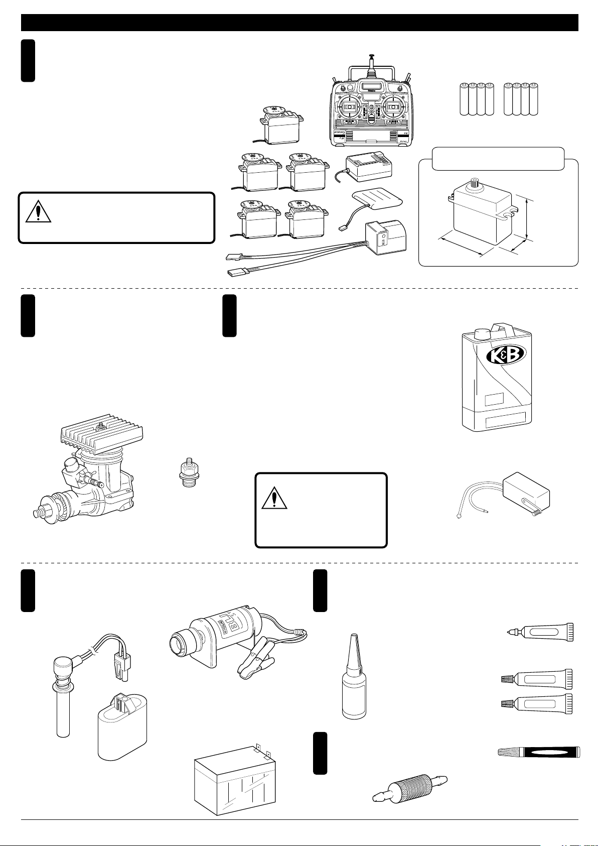
キットの他にそろえる物(1)REQUIRED FOR OPERATION (1)
エンジンヘリ用無線操縦機(プロポ)
1
と電池
Radio for engine-powered R/C helicopters,
and dry batteries
●このキットにはエンジンヘリ用(5サーボ+
ジャイロ)のプロポが必要です。
●プロポの取扱いは、プロポに付属の説明書
を参考にしてください。
●This kit requires a radio for engine-powered
R/C helicopters with 5 servos and 1 gyro.
●For more information on the radio, refer to
its explanations.
上空用(ヘリ用)のプロポセットを必ず
使用してください。(上空用以外使用禁止)
CAUTION: Only use a radio for R/C heli-
注意
copters! (Any other radio is prohibited!)
本説明書のプロポイラストは、Futaba取扱説明書より転載しました。
The illustrations showing the radio were taken from the Futaba radio explanations.
エンジン
2
Engine
●半完成キットをお買い求めの方は、エンジ
ンは取付け済です。マフラーは取付けてく
ださい。
●With semi-assembled kits, the engine
coms pre-installed. Install the muffler.
■ヘリ用30クラスエンジン
.30 class engine for helicopters
■プラグ
Glow Plug
■エンジンヘリ用プロポ
Radio for engine-powered
R/C helicopters
グロー燃料、燃料ポンプ
3
Glow Fuel and Fuel Pump
●模型用エンジン は専用のグロー燃料が必 要
です。ガソリンや 灯油 は使用できませんの
で注意してくださ い。 また、グロー燃料は
揮発性が高く引火 しや すいので取扱いには
充分注意してください。
●燃料は、ニトロ分10%以上が適しています。
●Engines for R/C models require glow fuel.
Do not use gasoline or kerosene; both
cannot be used! Also, be very care-ful when
han-dling glow fuel which is high-ly inflamma-ble and high-explosive!
●Fuel should contain at least 10% of nitro.
■単3乾電池(送信機用)
AA-size Batteries (for transmitter)
AAAA
使用できるサーボサイズ
SUITABLE SERVOS
39 ~ 41mm
■グロー燃料
Glow Fuel
500H
ngin
del e
o
m
●No. 6054 K&B500H燃料
K&B500H Model Engine Fuel
AAAA
33 ~ 36mm
19 ~ 20mm
el
e fu
始動用具
4
Required for engine starting:
■プラグヒーター
Plug Heater
●No. 96411 ワンタッチプラグヒーター
One-touch Plug Heater
2
警告
■スターター
Starter
●No. 1791 ブリッツスターター
Blitz Starter
■スターター用12Vバッテリー
12V Battery
●No. 71481 シールドバッテリー
Sealed Battery
(12V‑6.5A)
ガソリンや灯油は
使用禁止
WARNING: Gasoline
or kerosene cannot
be used!
接着剤等
5
Glues & Lubes
■ネジロック剤
Screw Locking Compound /
Screw Cement / Threadlocker
●ロックタイト Loctite
さらに用意すると良いもの
6
Equipment coming in handy
■燃料フィルター
Fuel Filter
■燃料ポンプ
Fuel Pump
No. 94402 中強度
Medium Strength
No. 94403 高強度
Hard Strength
●No. 1876/No. 39308 燃料フィルター
Fuel Filter
■グリス
Grease
No. 96506
■エポキシ接着剤
Epoxy Glue
■瞬間接着剤
Instant Glue
●No. 96627
クイックタイトジェルボーイ
GelBoy
ボールデフグリス
Ball Diff Grease
Grease
Epoxy A
Epoxy B
組立て前の注意(1) BEFORE YOU BEGIN (1)
組立てる前に説明書を良く読んで、おおよその構造を理解してから組立てに入ってください。
1
Read through the manual before you begin, so you will have an overall idea of what to do.
キットの内容をお確かめください。万一不良、不足がありましたら、お買い求めの販売店にご相談いただくか、
2
当社「ユーザー相談室」までご連絡ください。
Check all parts. If you find any defective or missing parts, contact your local dealer or our Kyosho Distributor.
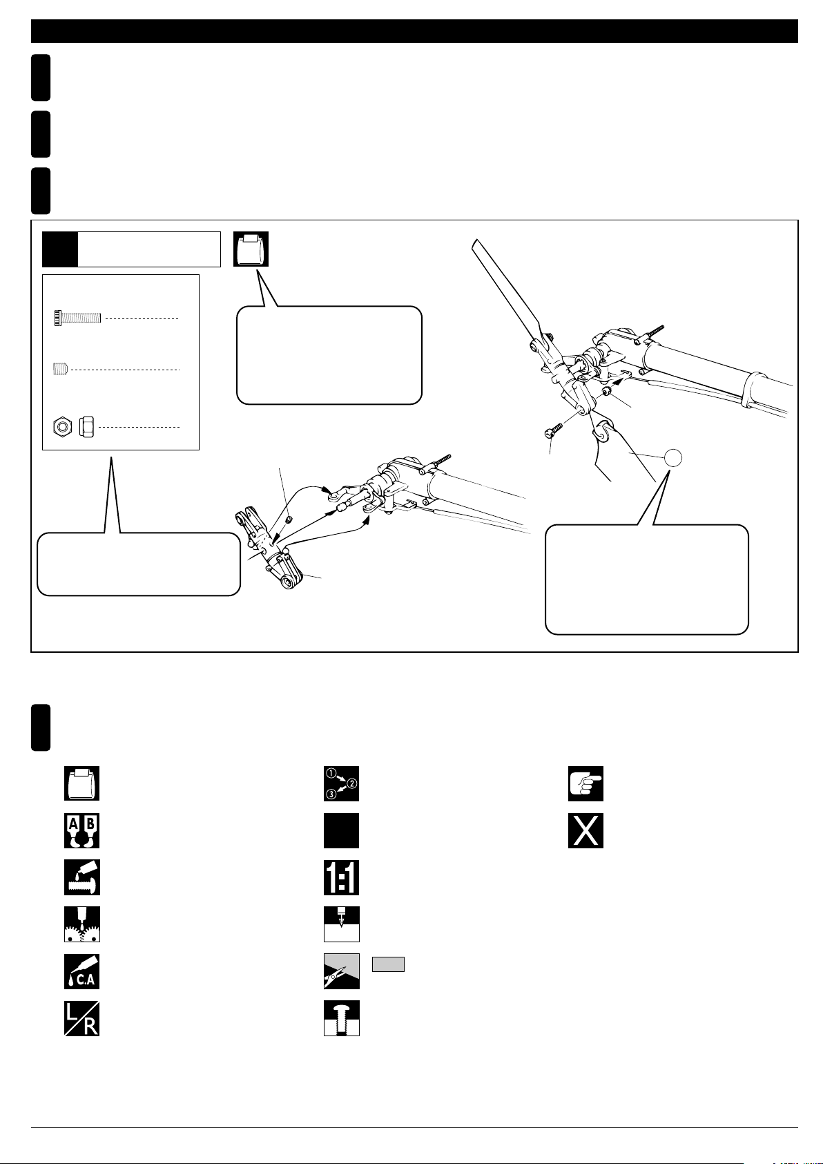
説明書の見かた
3
How to read the instruction manual:
〔説明例 Example〕
テール
Tail
9
2.6 x 10mm キャップビス
3 x 3mm セットビス
2.6mm ナイロンナット
小物部品の名前、原寸図、使用数。
Key Number, Part Name, True-to-scale
Diagram, Quantity Used
Cap Screw
2
Set Screw
1
Nylon Nut
2
HH-2
説明書内では多くのマークが使用
されています。マークに注意して
組立てを進めてください。
This instruction manual uses several symbols. Please note them
during the entire assembly.
3 x 3mm
テールローターアッセンブリー
Tail Rotor Assembly
2.6mm
2.6 x 10mm
キット内の部品は、ビス類を除いてキー
No.が付けられています。スペアパーツを
購入する時はキーNo.を参照して下さい。
All parts except screws are identified by
key numbers. For purchasing spare parts,
find the key no. of the part needed in the
spare part list and refer to the left column
to look up the corresponding order no.
92
説明書に使われているマーク
4
Symbols used throughout the instruction manual, comprise:
使用する袋詰。
Part bags used.
エポキシ接着剤で接着する。
Apply epoxy glue.
ネジロック剤を塗る。
Apply threadlocker (screw cement).
グリスを塗る。
Apply grease.
瞬間接着剤で接着する。
Apply instant glue (CA glue, super glue).
左右同じように組立てる。
Assemble left and right sides
the same way.
x2
2mm
番号の順に組立てる。
Assemble in the specified
order.
2セット組立てる(例)。
Assemble as many times as
specified (here: twice).
原寸図
True-to-scale diagram.
2mmの穴をあける(例)。
Drill holes with the specified
diameter (here: 2mm).
をカットする。
Cut off shaded portion.
仮止め。
Tentatively tighten.
注意して組立てる所。
Pay close attention here!
別購入品
Must be purchased separately!
4
組立て前の注意(2) BEFORE YOU BEGIN (2)
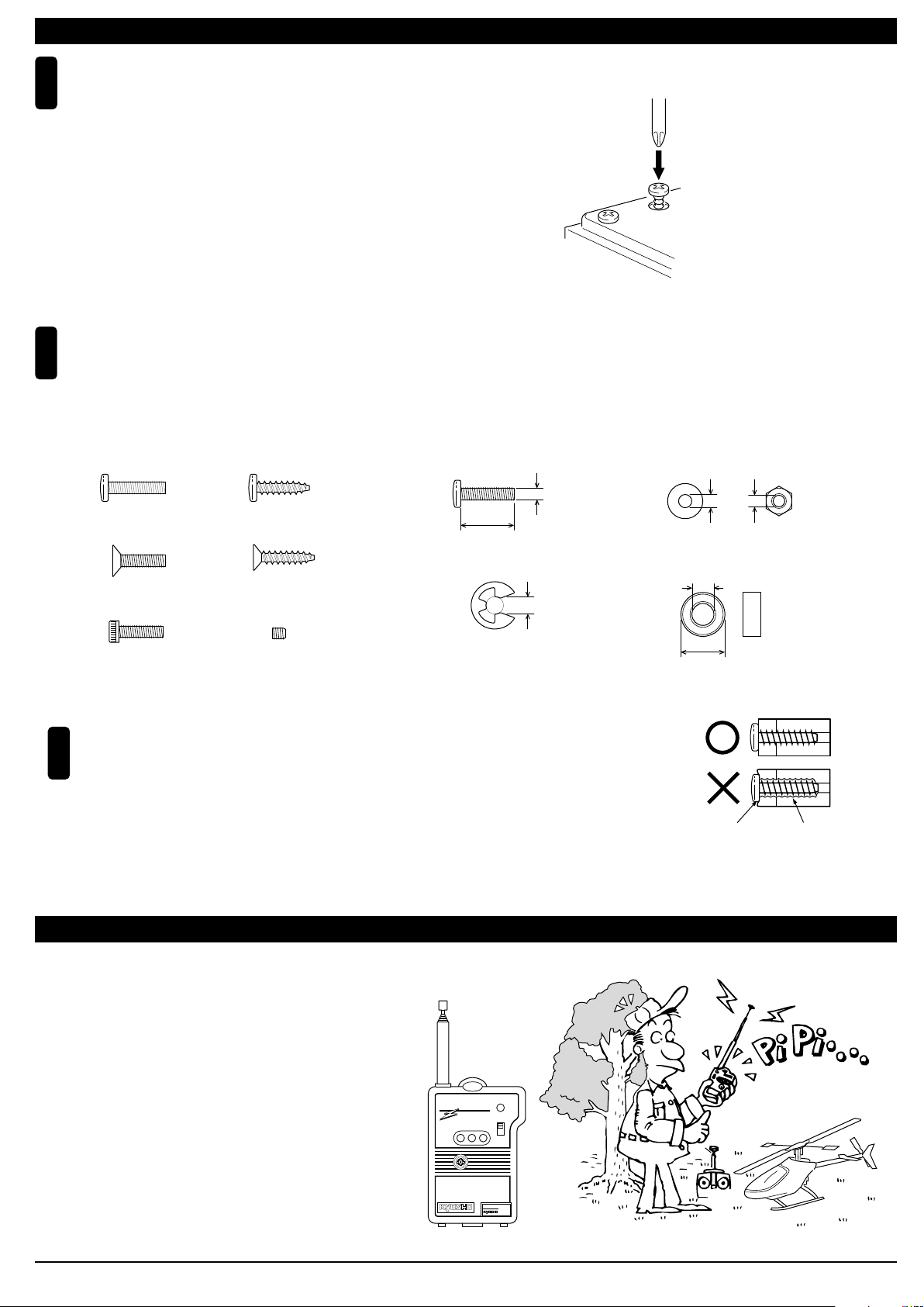
キット内の部品の中には、組立済みの部品があります。
5
念のためビス等のゆるみが無いか確認してから、組立て
てください。
Inside the kit, you will find assemblies, i.e. sections that are pre-assembled
and hence consist of more than one part. To make sure these assemblies
are safely assembled, check among others their screws for looseness. Only
then, build in the assemblies.
キットには、形や長さが違うビスや小物部品が多く入っています。説明書には原寸図がありますので確認してから組立て
6
てください。また、ビス類は多めに入っているものもありますので、予備としてお使いください。
This kit contains screws and hardware in different metric sizes and shapes. Before using them, check the screws on the true-to-scale diagrams on the
left side in each assembly step. Some screws are extras.
●ビスの種類 SCREWS
ビス Screw
サラビス
Flat Head (F/H) Screw
キャップビス
Cap Screw
TPビス
Self-tapping (TP) Screw
TPサラビス
TP F/H Screw
セットビス
Set Screw
●小物部品のサイズ例 OTHER HARDWARE
3x12mm ビス
Screw
3mm
12mm
E4 Eリング
E-ring
4mm
TPビスは、部品にネジを切りながらしめつけるビスです。しめこみが固い場合が
7
ありますが、部品が確実に固定されるまでしめこんでください。ただし、しめす
ぎるとネジがきかなくなりますので、部品が変形するまでしめないでください。
Self-tapping (TP) screws cut threads into the parts when being tightened. Excessive force may
permanently damage parts when tightening TP screws. It is recommended to stop tightening when
the part is attached or when some resistance is felt after the threaded portion enters the plastic.
3mm ワッシャー・ナット
Washer・Nut
3mm
5x10mm メタル・ベアリング
Metal Bushing・Bearing
5mm
10mm
Correct
Wrong
しめすぎ
Overtightened.
ビスがきかない
The threads are stripped.
パーソナルバンドモニターについて ABOUT THE "PERSONAL FREQUENCY MONITOR"
愛機の飛行前に、使うバンドのクリスタルをセット
してスイッチオン! 同一バンドの電波をキャッチ
するとブザー音とLEDの光で警告。
Before operating your helicopter, plug the crystal of your
frequency into the Personal Fre-quency Monitor. As soon
as you switch it on, you'll know for sure through an interfe-rence signal and LED lamps whether somebody else is on
your fre-quency or not!
No.80591 (40MHz)
No.80592 (72MHz)
●6,000
専用クリスタル別売
Special crystals are
available at Kyosho!
PERSONAL
BAND MONITOR
CORPORATION
No.80591
KYOSHO CORPRATION
KYOSHO
JRMSA
40MHZ
ON
OFF
77
5
●この取扱説明書は組立キット(No.21705)/エンジン付半完成キット(No.21702)共通の説明書です。
お買い上げいただいた商品に合わせて組立ては以下のようにおこなってください。
組立キット: 〜 全て
半完成キット: 〜 全て
491
4915 28
● This instruction manual is both for kit No.21705 and semi-assembled kit No.21702 with engine.
When referring to the instructions for completing the assembly, make the following distinctions.
NEXUS 30S type S (assembly kit) : All steps from through .
NEXUS 30S type S (semi-assembled) : All steps from through .
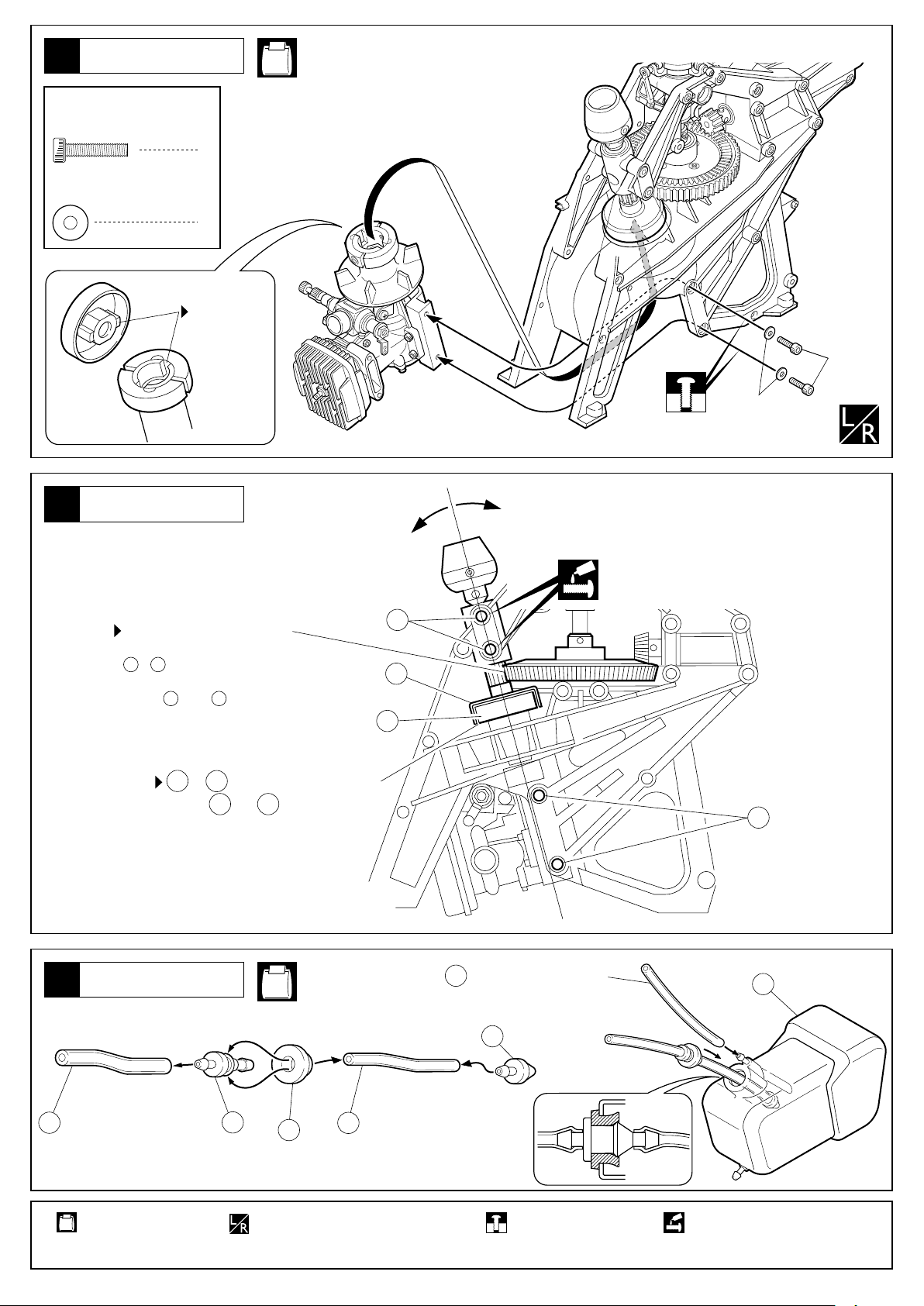
クラッチ
1
Clutch
4×5mm セットビス
Set Screw
3×30mm キャップビス
Cap Screw
3mm ナイロンナット
Nylon Nut
5×10mm ベアリング
83
Ball Bearing
5×16mm ベアリング
18
Ball Bearing
2
49
8×16mm ベアリング
1
1
1
Ball Bearing
2.5×15mm ピン
379A
Pin
NE-B, NE-6
3mm
382
1
381
83
1
(接着済)
1
209
(glued)
(取付済)
(pre-installed)
379A
491
4915 28
384A
4×5mm
18
380A
378
(取付済)
(pre-installed)
385
3×30mm
4×5mm
平らな所にセットビス
をしめこむ。
Firmly tighten the set
screw to the flat.
383
(取付済)
49
(pre-installed)
テールドライブギヤ
2
Tail Drive Gear
4×5mmセットビス
Set Screw
2×10mmスプリングピン
58
Spring Pin
5×13mmベアリング
56
Ball Bearing
使用する袋詰。
Part bags used.
6
NE-2, NE-6
1
1
5×16mmベアリング
18
Ball Bearing
1
原寸図
原寸図
True-to-scale diagram.
True-to-scale diagram.
1
386
エポキシ接着剤で接着する。
Apply epoxy glue.
419
4×5mm
56
18
58
平らな所にセットビスをしめこむ。
Firmly tighten the set screw to the flat.
18
22.5mm
ネジロック剤を塗る。
Apply threadlocker
(screw cement).
57
56
3
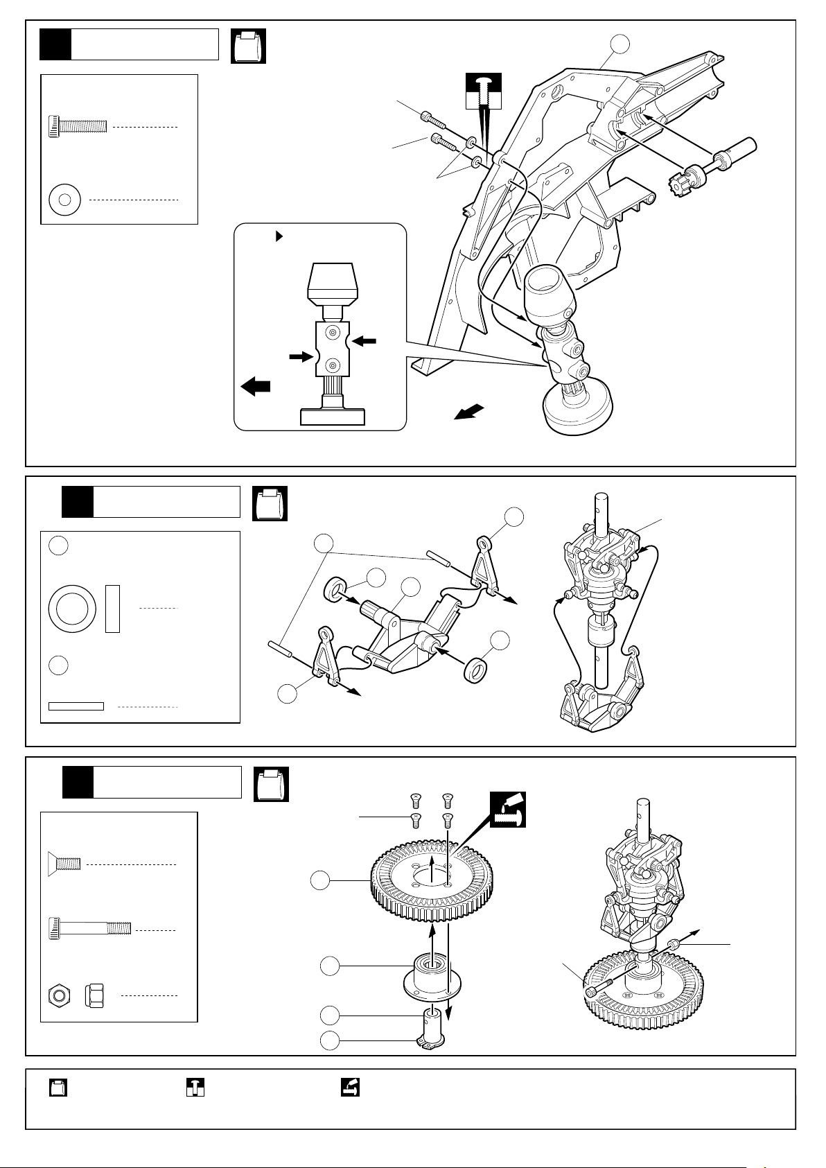
フレーム
Frame
NE-5
369
3×12mm キャップビス
Cap Screw
3×8mm ワッシャー
Washer
3×12mm
2
3×12mm
3×8mm
2
向きに注意する。
Note the direction.
前
Front
前
Front
マスト
4
Mast
371
8×12mm プラスチックブッシュ
Plastic Bushing
59
2×14mm ピン
Pin
メインギヤ
5
Main Gear
3×8mm サラビス
F/H Screw
3×18mm キャップビス
Cap Screw
3mm ナイロンナット
Nylon Nut
NE-2, NE-3, NE-4
31
59
371
374
2
371
2
31
マストアッセンブリー
Mast Assembly
NE-4
3×8mm
4
503
1
3mm
48
3×18mm
使用する袋詰。
Part bags used.
1
仮止め。
Tentatively tighten.
46
150
ネジロック剤を塗る。
Apply threadlocker
(screw cement).
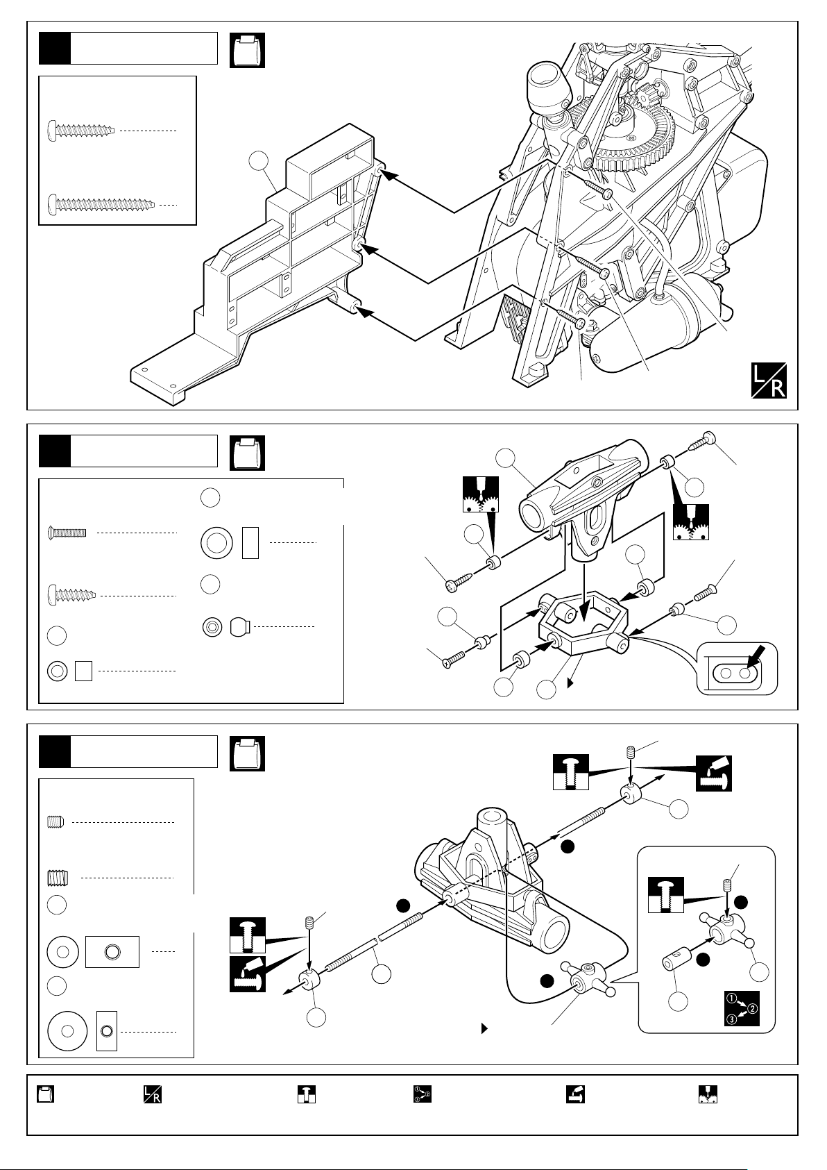
7
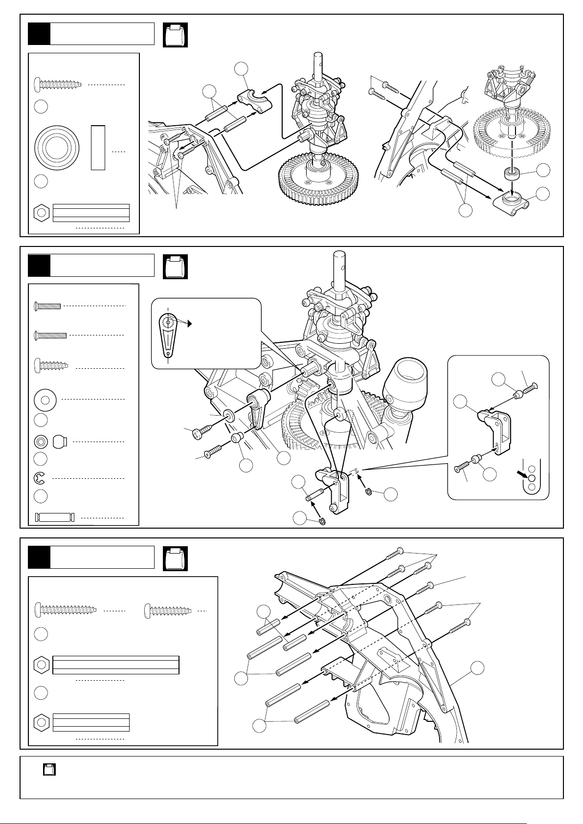
6
マスト
Mast
NE-2, NE-5, NE-6
3×15mm TPビス
Screw
49
8×16mm ベアリング
Ball Bearing
373
インサートナット(S)
Insert Nut (S)
コントロールレバー
7
Control Lever
2×8mm サラ小丸ビス
RT/H Screw
2×10mm サラ小丸ビス
RT/H Screw
3×10mm TPビス
Screw
3×8mm ワッシャー
Washer
212
リンケージボール
Linkage Ball
230
Eリング E2.0
E-ring
33
3×14mm シャフト
Shaft
4
1
4
2
1
1
1
3
2
1
3×15mm
3×10mm
2×10mm
373
NE-4
印を合わせる。
Align both marks.
3×8mm
388
212
418
33
230
3×15mm
230
49
387
373
2×8mm
212
188
212
2×8mm
フレーム
8
Frame
3×20mm TPビス
Screw
372
インサートナット(L)
Insert Nut (L)
373
インサートナット(S)
Insert Nut (S)
使用する袋詰。
Part bags used.
8
3×15mm TPビス
Screw
2
4
2
NE-5
3×15mm
3×15mm
3×20mm
4
373
370
372
372
フレーム
9
Frame
3×12mm キャップビス
Cap Screw
3×15mm TPビス
Screw
3×20mm TPビス
Screw
3×8mm ワッシャー
Washer
13×16mm シム
535
Shim
NE-5, NE-6
● メインギヤのバックラッシュ調整
を外し、図の位置にシムを入れてください。
387
シムの枚数は、バックラッシュの量に合わせてください。
Main Gear Backlash Adjustment.
2
8
2
2
Remove the lower ball bearing case and insert shims as per
diagram. The number of shims used will affect the backlash.
388
387
13 x 16mmシム
Shim
387
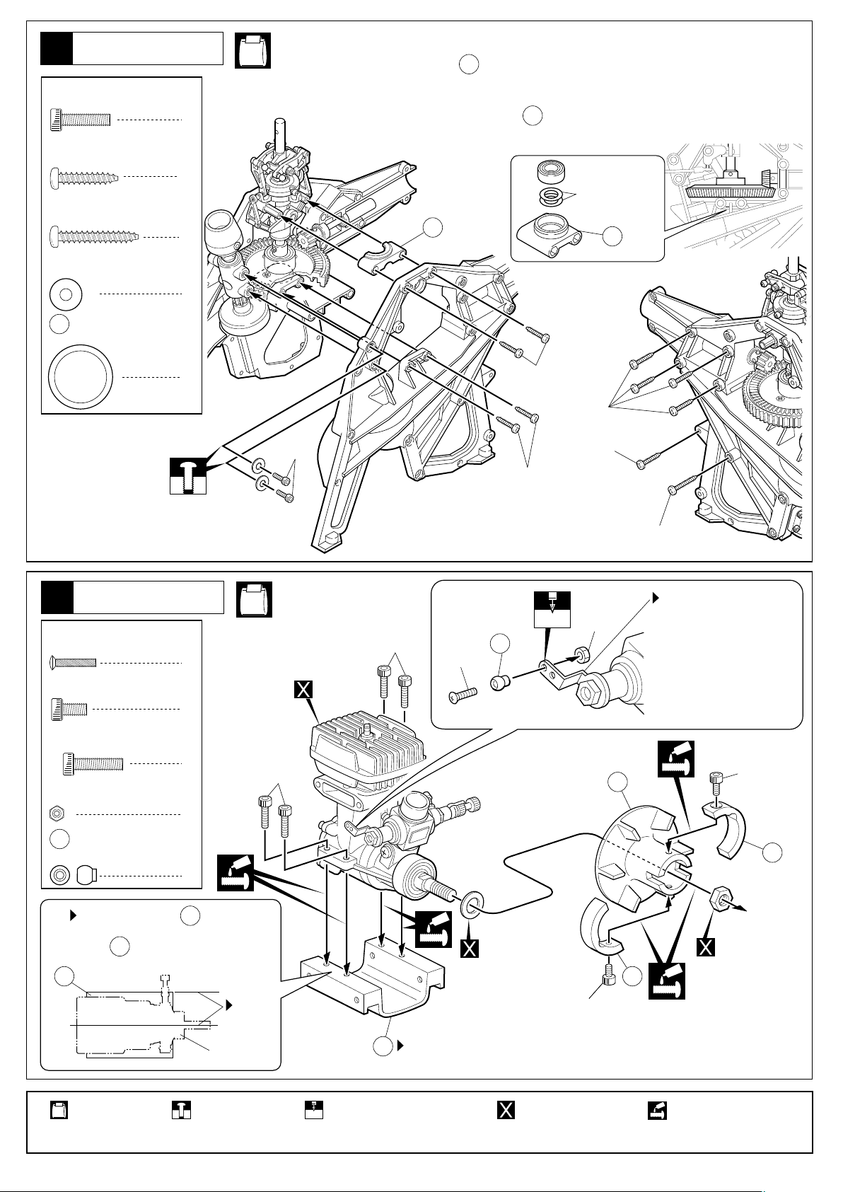
エンジン
10
Engine
2×10mm サラ小丸ビス
RT/H Screw
3×6mm キャップビス
Cap Screw
3×12mm キャップビス
Cap Screw
2mm ナット
Nut
3×15mm
212
3×15mm
2mm
3×15mm
3×20mm
2mm
376
3×20mm
O.S.32SXエンジンを使用
する場合は、キット付属の
物と交換する。
With an O.S. 32SX engine,
replace this part with the
one supplied with the kit.
3×6mm
2
3×12mm
NE-6, NE-8
3×12mm
1
エンジン
2
4
3×12mm
1
Engine.
2×10mm
リンケージボール
212
Linkage Ball
1
エンジンの中心線と が平行に
なるように取付ける。
Install so it is parallel with the
375
center line of the engine.
375
使用する袋詰。
Part bags used.
375
平行。
Parallel
エンジン
Engine.
仮止め。
Tentatively tighten.
向きに注意。
375
Note the direction.
2mmの穴をあける(例)。
2mm
Drill holes with the specified
diameter (here: 2mm).
エンジン付属
Supplied with the
engine.
別購入品
Must be purchased
separately!
3×6mm
3×6mm
502
502
エンジン付属
Supplied with the
engine.
ネジロック剤を塗る。
Apply threadlocker
(screw cement).
9
エンジン
11
Engine
3×14mm キャップビス
Cap Screw
3×8mm ワッシャー
Washer
メインギヤ
12
Main Gear
NE-6
4
4
形を合わせる。
Fit together.
3×14mm
3×8mm
● 図のように、ギヤのバックラッシュを
調整します。
Adjust the backlash as per diagram and
explanations.
紙1〜2枚をはさんだくらいの
バッククラッシュに調整し、
B 、A の順でビスを締める。
Tighten the screws in the
order B and A with two
sheets of paper inserted
between the gears.
377
381
と が接触しないようにする。
Ensure and do not contact.
377 381
燃料タンク
13
Fuel Tank
NE-7
377
381
A
B
393
シリコンチューブ(太)
Silicone Tube (thick)
389
シリコンチューブ(太)
393
Silicone Tube (thick)
使用する袋詰。
Part bags used.
10
390
391
左右同じように組立てる。
Assemble left and right sides the same way.
シリコンチューブ(細)
392
Silicone Tube (thin)
110
仮止め。
Tentatively tighten.
ネジロック剤を塗る。
Apply threadlocker
(screw cement).

燃料タンク
14
Fuel Tank
3×10mm TPビス
Screw
NE-7
2
3×10mm
394
マフラー
15
Muffler
4×5mm ビス
Screw
4×14mm キャップビス
Cap Screw
3×35mm キャップビス
Cap Screw
3mm ナット
Nut
4mm ナット
Nut
3×118mm ビス
Screw
1
1
2
2
1
1
533
3×118mm
NE-9
400
4×14mm
402
4mm
4×5mm
3×35mm
3mm
401
398
399
397
3mm
コントロールレバー
16
Control Lever
3×20mm TPビス
Screw
3×8mm ワッシャー
Washer
37
エルロンレバーカラー
Aileron Lever Collar
使用する袋詰。
Part bags used.
NE-4
1
1
1
左右同じように組立てる。
Assemble left and right sides the same way.
37
30
36
3×8mm
3×20mm
11
フレーム
17
Frame
3×15mm TPビス
Screw
NE-5, NE-12
4
3×25mm TPビス
Screw
ローターヘッド
18
Rotor Head
2×8mm サラ小丸ビス
RT/H Screw
3×10mm TPビス
Screw
352
3×5mm カラー
Collar
395
2
3×15mm
3×15mm
NE-1, NE-2
351
5×8mm プラスチックブッシュ
Plastic Bushing
2
212
2
2
リンケージボール
Linkage Ball
2
2
3×10mm
212
2×8mm
352
358
351
向きに注意。
350
Note the direction.
3×25mm
351
3×10mm
352
2×8mm
212
ローターヘッド
19
Rotor Head
3×4mm セットビス
Set Screw
4×5mm セットビス
Set Screw
6
ヒラーコントロールレバーブッシュ
Hiller Control Lever Bushing
436
3mm ストッパー
Stopper
使用する袋詰。
Part bags used.
12
NE-1, NE-13
2
1
1
2
左右同じように組立てる。
Assemble left and right
sides the same way.
3×4mm
4
4
436
仮止め。
Tentatively tighten.
3
番号の順に組立てる。
Assemble in the specified
order.
5
4
向きに注意。
Note the direction.
3×4mm
436
6
ネジロック剤を塗る。
Apply threadlocker
(screw cement).
4×5mm
2
1
グリスを塗る。
グリスを塗る。
Apply grease.
Apply grease.
7
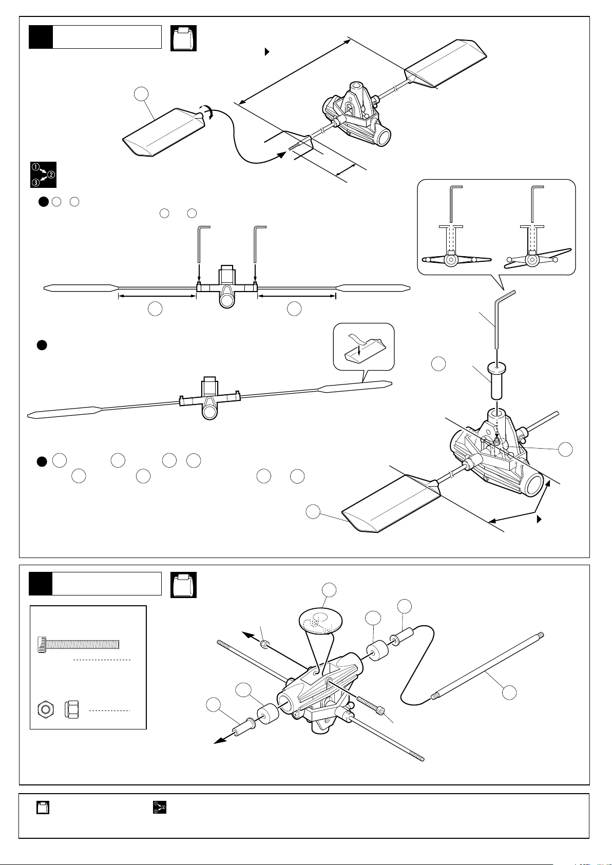
ローターヘッド
20
Rotor Head
148
1
A Ð A ' が同一寸法になる位置でセットビスをしめる。
Tighten the set screws when A and A ' are equally long.
NE-1
平行
Parallel
約30mm
About 30mm
◯ ×
A
2
左右の重さがつり合うまで軽い方にテープを貼る。
To balance left and right ends, place a piece of tape to the lighter end.
417
3
を使用して を固定し、 と が平行になる位置でセットビスをしめる。
Hold in place with . Tighten the set screw when and are parallel.
7
ローターヘッド
21
Rotor Head
3×25mm キャップビス
Cap Screw
7
417
7
148
7
NE-1
3mm
A
'
148
148
357
536
六角レンチ(2mm)
Hex Wrench(2mm)
417
(治具)
( jig )
354
7
平行
Parallel
3mm ナイロンナット
Nylon Nut
使用する袋詰。
Part bags used.
1
536
1
番号の順に組立てる。
Assemble in the specified order.
354
3×25mm
355
13
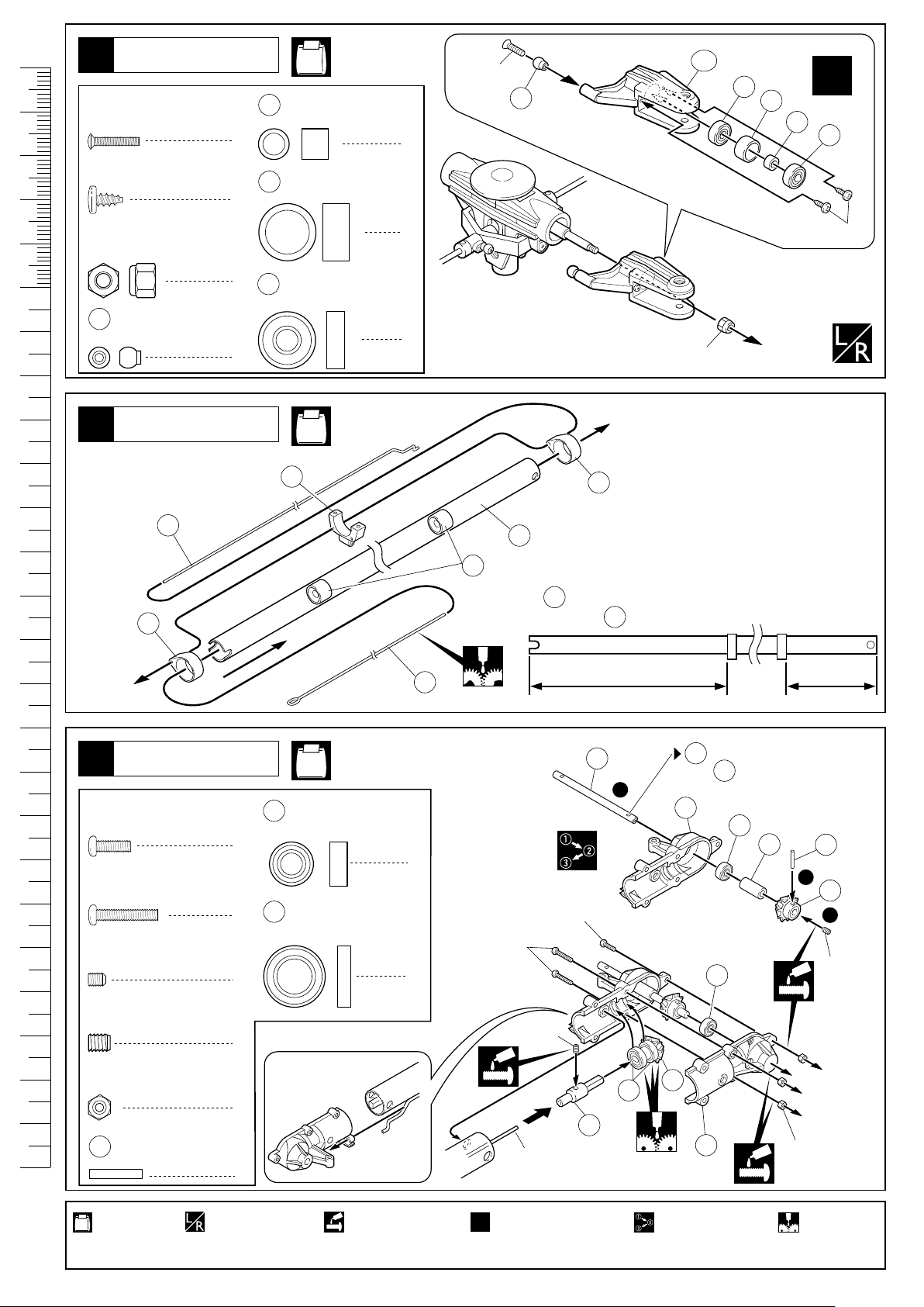
cm
ローターヘッド
22
Rotor Head
2×10mm サラ小丸ビス
RT/H Screw
3×6mm TPビス
Screw
NE-1, NE-2
2×10mm
16
5×7mm スペーサー
Spacer
2
10×13mm スペーサー
17
4
Spacer
2
212
353A
56
17
x2
16
56
4mm ナイロンナット
Nylon Nut
543210 109876 1514131211 2019181716 2524232221
212
リンケージボール
Linkage Ball
2
テールブーム
23
Tail Boom
408
403
5×13mm ベアリング
56
Ball Bearing
2
405
NE-12, NE-13
2
4
403
177
(取付済)
235
(factory - inserted)
● の位置
403
Positioning
403
4mm
3×6mm
テールギヤボックス
24
Tail Gearbox
2.6×8mm ビス
Screw
2.6×14mm ビス
Screw
3×4mm セットビス
Set Screw
4×5mm セットビス
Set Screw
2.6mm ナット
Nut
2×12mm ピン
79
Pin
404
220mm 120mm
を通す。
NE-2, NE-10
5×10mm ベアリング
83
Ball Bearing
1
8×14mm ベアリング
76
2
1
1
3
1
Ball Bearing
2
2
2.6×14mm
4×5mm
2.6×8mm
▲
Dカット有り
平らなところに合わす
Flat end of shaft
537
1
76
75
79
Pass through this hole.
79
80
83
84
83
77
81
79
2
78
3
3×4mm
2.6mm
使用する袋詰。
Part bags used.
14
左右同じように
組立てる。
Assemble left and right
sides the same way.
ネジロック剤を塗る。
Apply threadlocker
(screw cement).
2セット組立てる(例)。
x2
Assemble as many times as
specified (here: twice).
番号の順に組立てる。
Assemble in the
specified order.
グリスを塗る。
Apply grease.
 Loading...