

Kyosho Landjump 4wd, Landjump 4wd INTEGRA User Manual
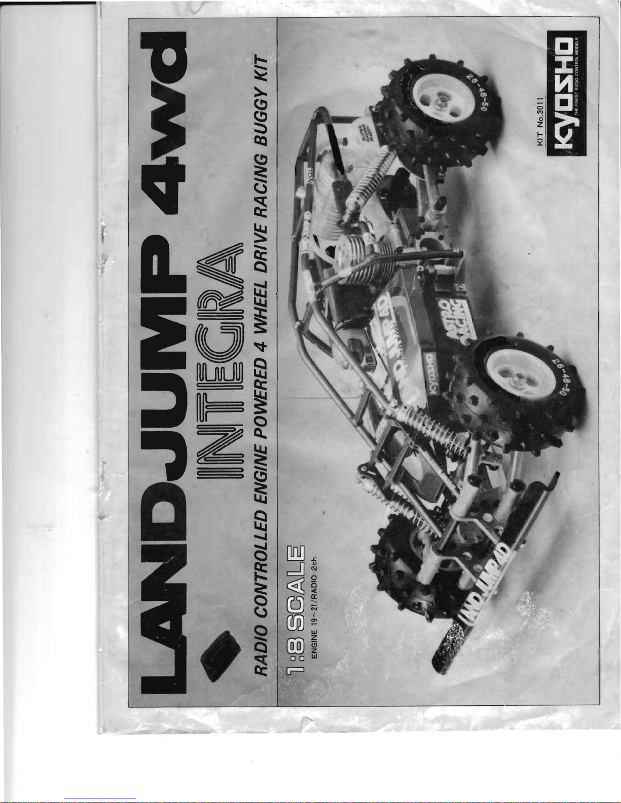
LAND
JUMP
4D
No.2397
============
4
Wheel
Drive
Buggy
===================
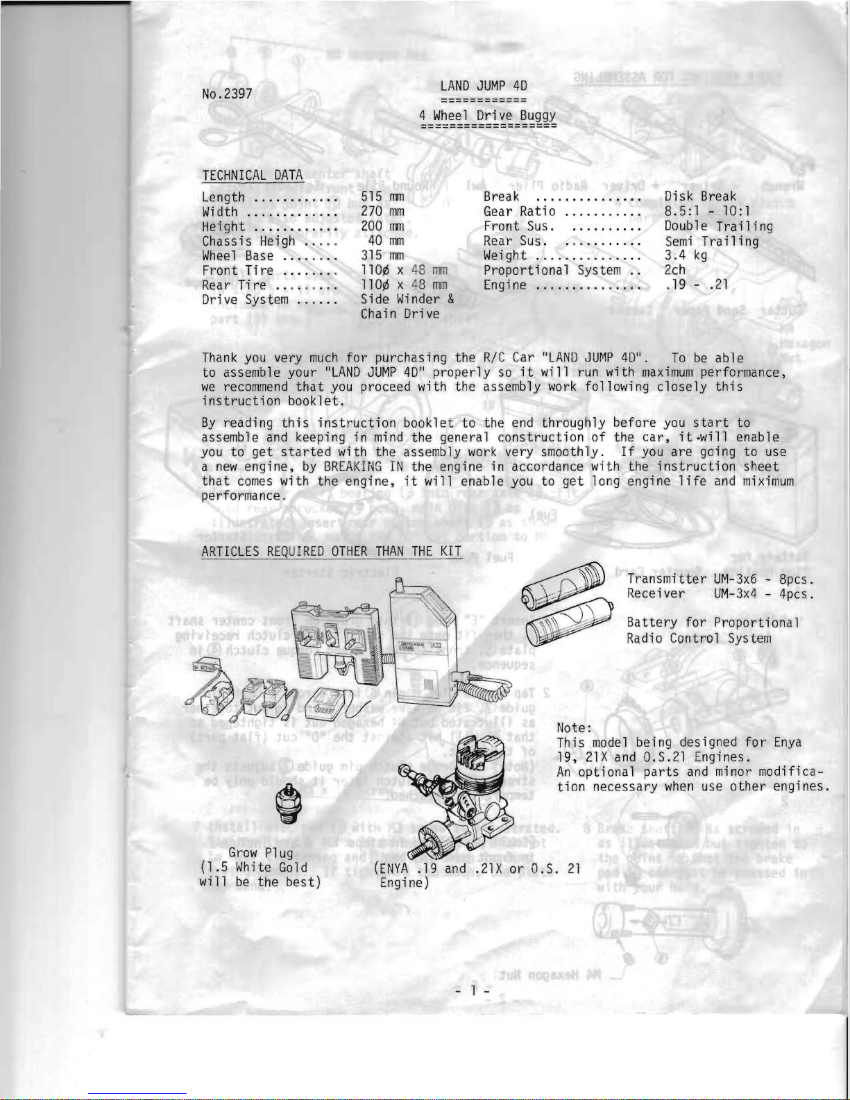
TECHNICAL
DATA
Length
...........
.
515
rrm
Break
..............
.
Di
s k
Break
Wi
dth
............
.
270
mm
Gear
Rati 0
••••••••••.
8.5:1 -
10:1
Height
...........
.
200
rrm
Front
Sus
..........
.
Doub
1 e
Tra ili
ng
Chassis
Heigh
.. ..
.
40
mm
Rear Sus. . .
........
.
Semi
Trailing
Wheel
Base
.....
. . .
315
mm
Weight
..............
.
3.4
kg
Front Tire
.......
.
11
O¢
x
48
rT1l1
Proportional
System
..
2ch
Rear
Tire ... . ... . .
11
O¢
x 48
rrm
Engine
..............
. .
19 -.21
Drive
System
.....
.
Side
Winder
&
Chain
Drive
Thank
you
very
much
for
purchasing the
RIC
Car
"LAND
JU~1P
4D".
To
be
able
to assemble your
"LAND
JUMP
4D"
properly
so
it
will
run
with
maximum
performance,
we
recommend
that
you
proceed with the assembly
work
following
closely
this
instruction
booklet.
By
reading
this
instruction
booklet to the
end
throughly before
you
start
to
assemble
and
keeping in
mind
the general construction of the
car,
it·will
enable
you
to get
started
with the assembly
work
very smoothly.
If
you
are going to use
a
new
engine,
by
BREAKING
IN
the engine in accordance with the
instruction
sheet
that
comes
with the engine,
it
will enable
you
to
get
long engine
life
and
miximum
performance.
ARTICLES
REQUIRED
OTHER
THAN
THE
KIT
Transmitter
UM-3x6
- 8pcs.
Receiver
UM-3x4
- 4pcs.
Battery
for
Proportional
Radio
Control
System
Note:
This
model
being designed
for
Enya
19,
21X
and
0.S.21 Engines.
An
optional
parts
and
minor modifica-
tion
necessary
when
use
other
engines.
Grow
P1
ug
(1 . 5
Wh
ite
Go
1d
(ENYA
.19
and
.21X
or O.S.
21
will
be
the best)
Engine)
- 1 -
2
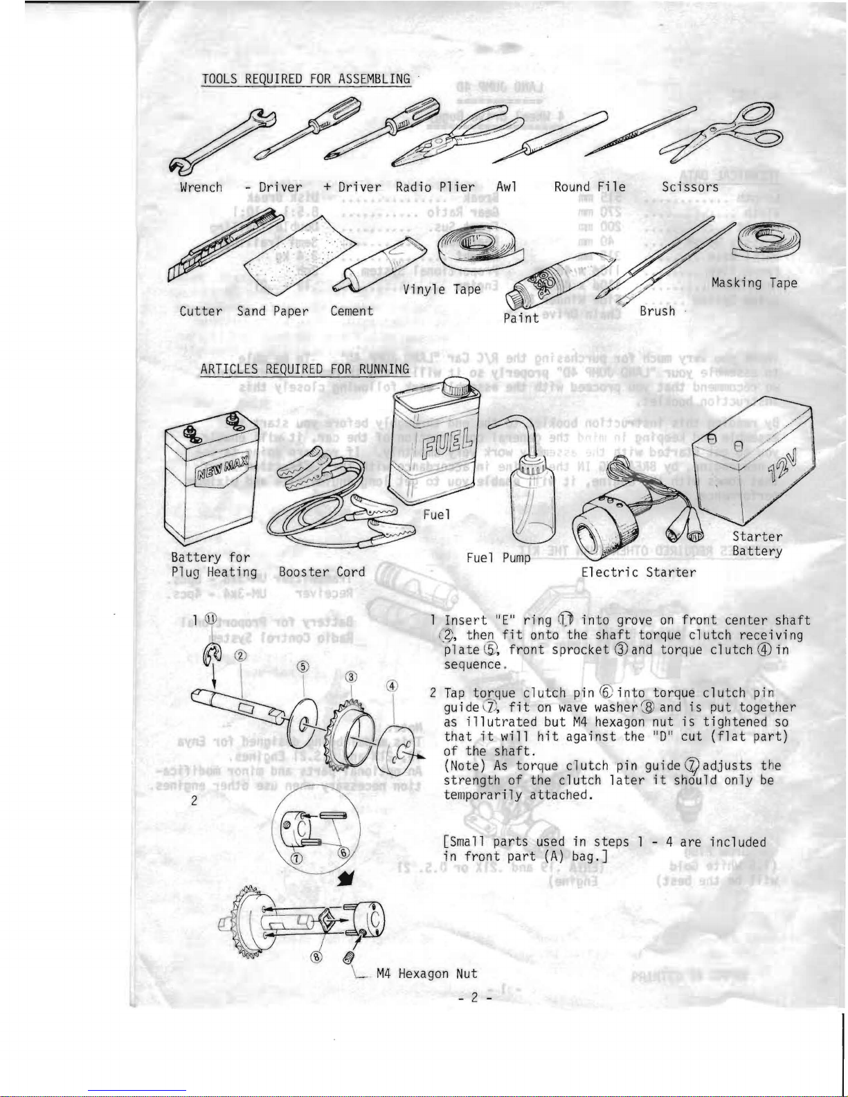
TOOLS
REQUIRED
FOR
ASSEMBLING
.
Wrench
- Driver + Driver
Radio
Plier
Awl
Round
File
Scissors
..
;>
A>(~
~
Masking
Tape
~;nYle
T~P~
~
.
Cutter
Sand
Paper
Cement
Pa
i nt
ARTICLES
REQUIRED
FOR
RUNNING
Battery
for
Fue1 Pump
Plug
Heating Booster
Cord
Electric
Starter
1 Ins e
rt
"E"
ring
OJ
into
grove
on
front
center
shaft
(
2),
then
fit
onto the
shaft
torque cl utch recei
vi
ng
plate
®.
front
sprocket
Q)
and
torque
clutch@in
sequence .
Tap
torque clutch pin
~
into
torque
clutch
pin
guide \l;,
fit
on
wave
washer '])
and
is
put
together
as
illutrated
but
M4
hexagon
nut
is
tightened
so
that
it
l'Ii11
hit
against
the
"0"
cut
(flat
part)
of the
shaft.
(Note)
As
torque clutch pin guideCZ)adjusts t he
strength
of
the clutch l a
ter
it
should only
be
temporarily attached.
[Small parts used in steps 1 - 4 are included
in
front
part
(A)
bag.]
_
M4
Hexagon
Nut
- 2 -
~
~
®
CD
M4
Hexagon
Nut
rr~
.
\ .
~""~
~
M4
Hexagon
Nut
~ '~/&-
~
1
\
/
~
I .
®
~
i I
o~
C
__
~
I
:c
l~(bt~
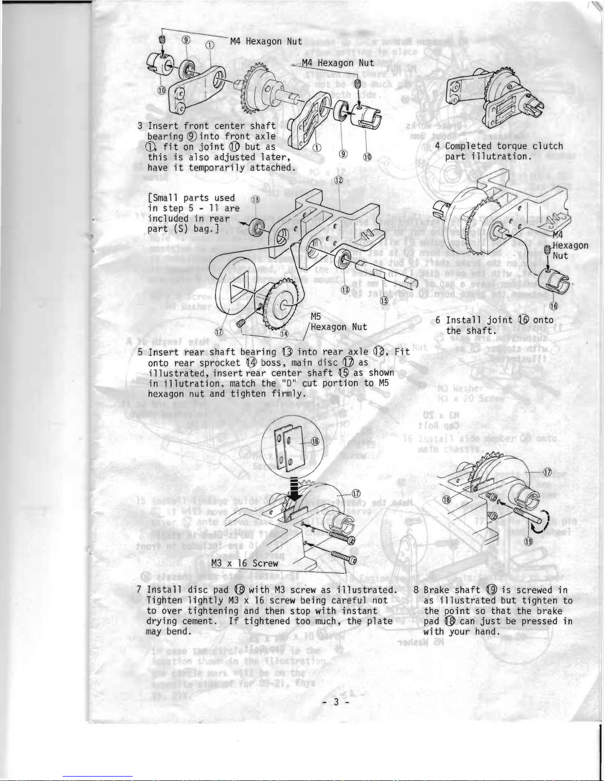
3
Insert
front
center
shaft
~
'\
'f
l:k1!}
bearing
®into
front
axle \ \ \
ffi
fit
on
joint@
but as
CD
C
this
is
also adjusted
later,
® ®
have
it
temporarily
attached.
[Small
instep 5 incl
uded
in
part
(S) bag.]
parts
used
~
11
a re I
rear
~
~
M5
. /
Hexagon
Nut
5
Insert
rear
shaft
bearing ~ into
rear
axle
~,
Fit
onto
rear
sprocket ~boss,
main
disc
Q}
as
ill
us
tra
ted,
insert
rea r
center
shaft
(3l
as
shown
in
illutration,
match
the
"0"
cut portion to
M5
hexagon
nut
and
tighten
firmly.
4 Completed torque clutch
part
illutration.
~~
i
~~
--
j
/
@tHexagon
,,ret
~.
i
@
6
Install
joint
t~
onto
the
shaft.
7
Install
disc
pad ~with
M3
screw as
illustrated.
8
Brake
shaft ~ is
screwed in
Tighten
lightly
M3 x 16
screw being careful not
as
illustrated
but
tighten
to
to over
tightening
and
then stop with
instant
the point so
that
the brake
drying cement.
If
tightened too
much,
the
plate
pad ~can
just
be
pressed in
may
bend.
with your hand.
- 3 -
C
I c
~
~
\\
~
M5
Washer
@
M3 x 25
Screw
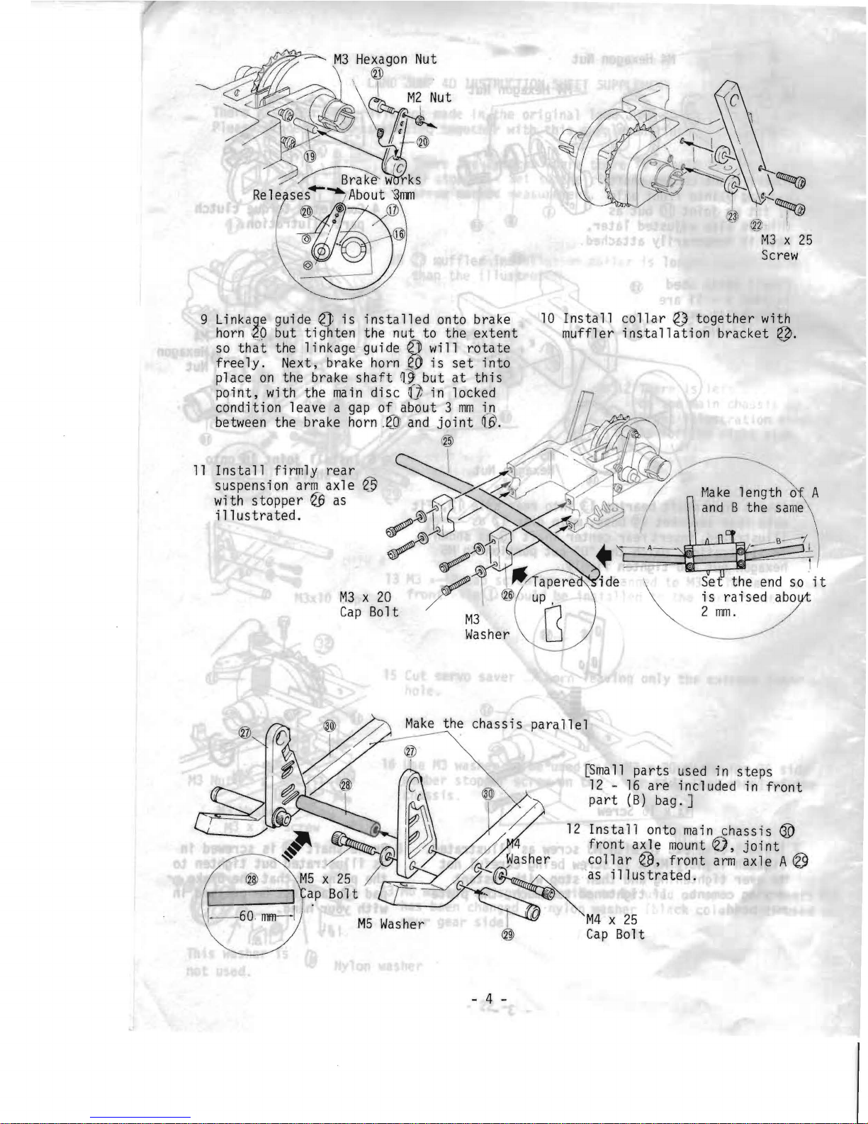
9 Linkage guide
eJ
is
installed
onto brake
10
Install
collar
~
together
with
horn
~O
but
tighten
the nut to the
extent
muffler
installation
bracket
~.
so
that
the 1i
nkage
gu ide
e)J
wi
11
rota
te
freely.
Next, brake horn
eO
is
set
into
place
on
the brake
shaft
n,~
but
at
this
point,
with the
main
disc
Q]
in locked
condition leave a
gap
of
about 3
mm
i~
between the brake
horn ,(0:
and
joint
161.
®
11
Install
firmly
rear
~
\
'-...
~
~
~
}
~~
A~
~
Y
~
"
~
"
suspension
arm
axle
~
~~
~
Make
length 0 A
with stopper
ell
as
~
'>....
~
and
B the
same
illustrated.
~1
J)/
~
~
~f'
+
~W)
===
up
r)
L':l
end
so
it
M3
x
20
/ @
is
raised
aboi)'t
Cap
Bolt
M3
2
mm.
/
Washer
~~~
~
the chassis
parallel
~mall
parts
used in steps
~
12 -16
are included in
front
,
part
(B)
bag. ]
~
12
Install
onto
main
chass is
GO
I
l'l
front
axle
mount
0,
joint
~
~asher
collar
~,
front
arm
axle A
~
/
~as
illustrated
.
G.
_
..
~
M4 x 25
~
Cap
Bolt
- 4 -
0
,ce
and
after
setting
in place
has
been
finished,
there will
too
much
p1a1
Nut
-
M3 x 20
Cap
Bolt
/
~
\
(
~~
ighten
so
r~
not
be
~
on
Loosen
up
~
both
side,
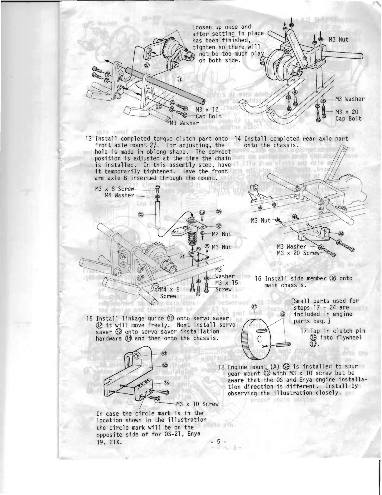
13
Install
completed torque clutch
part
onto
14
Install
completed
rear
axle
part
front
axle
mount
e).
For
adjusting,
the onto the
chassis.
hole
is
made
in oblong shape.
The
correct
position
is
adjusted
at
the time the chain
is
installed.
In
this
assembly
step,
have
it
temporarily tightened.
Have
the
front
arm
axle B
lnserted
through the
mount.
M3
x 8
Screw
-------
li
M4
Washer --_
16
Install
side
member ~ onto
main
chassis.
@
[Small
parts
used
for
1(>
steps
17 -24
are
included in engine
15
Install
linkage guide
G5
onto servo saver
parts
bag. ]
~
it
will
move
freely.
Next
install
servo
saver
~
onto servo saver
installation
17
Tap
in clutch pin
hardware
~
and
then onto the
chassis.
~.into
flywheel
"
....
,\_-
®l
- @
18
Engine
mount
(A)
~
is
installed
to spur
gear
mount ~with
M3 x 10
screw but
be
aware
that
the
OS
and
Enya
engine
installa-
tion
direction
is
different.
Install
by
observing the
illustration
closely.
x
10
Screw
In
case the
circle
mark
is
in the
location
shown
in the
illustration
the
circle
mark
will
be
on
the
opposite side
of
for
OS-2l.
Enya
19.
21X.
-5-
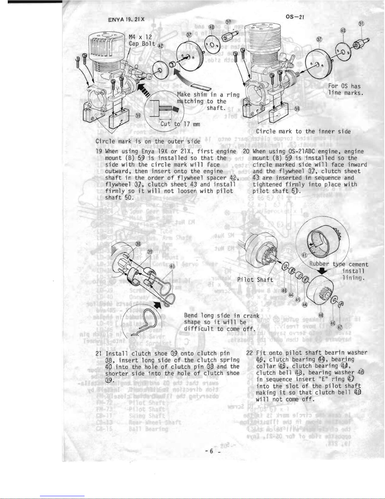
05-21
Circle
mark
to the inner
side
mm
For
OS
has
1 ine marks.
20
When
using .pS-21
ABC
engine. engine
mcunt
(B)!?9
is
installed
so the
circle
marked
side
will
face inward
and
the flywheel 3-
]:
,
clutch
sheet
43
are
inserted
in sequence
and
tightened
firmly
into
place with
pilot
shaft
~).
Circle
mark
is
on
the outer
side
19
When
using
Enya
19X
or
21X , first
engine
mount
(B)
~~
is
installed
so
that
the
side
with the
circle
mark
will
face
outward, then
insert
onto the engine
shaft
in the
order
of
flY\'Iheel spacer
4~'
,
flywheel
'
~J,
clutch
sheet
4)
and
install
fi
rmly
50
it
will not loosen with
pil
ot
shaft '50
.
e
be
off
.
cement
install
lining.
Bend
long
side
in crank
shape
so
it
will
difficult
to
come
21
Install
cl utch shoe
Q9
onto cl utch
pi
n
22
Fjt
onto
pilot
shaft
bearin washer
G8.
insert
long
side
of the
clutch
spring
~y,
clutch
bearing
@.
bearing
(0
into
the hole
of
clutch
pin
88
and
the
collar~.
clutch
bearing
~~.
shorter
side
into
the hole
of
clutch
shoe
cl utch
bellW.
bearing washer
4£1
\19.
in sequence
insert
"E"
ring
~
into
the
slot
of the
pilot
shaft
making
it
so
that
clutch
bell
©
will
not
come
off.
- 6 -
r~6
Washer
_,;
M6
Washer
r15
Nut
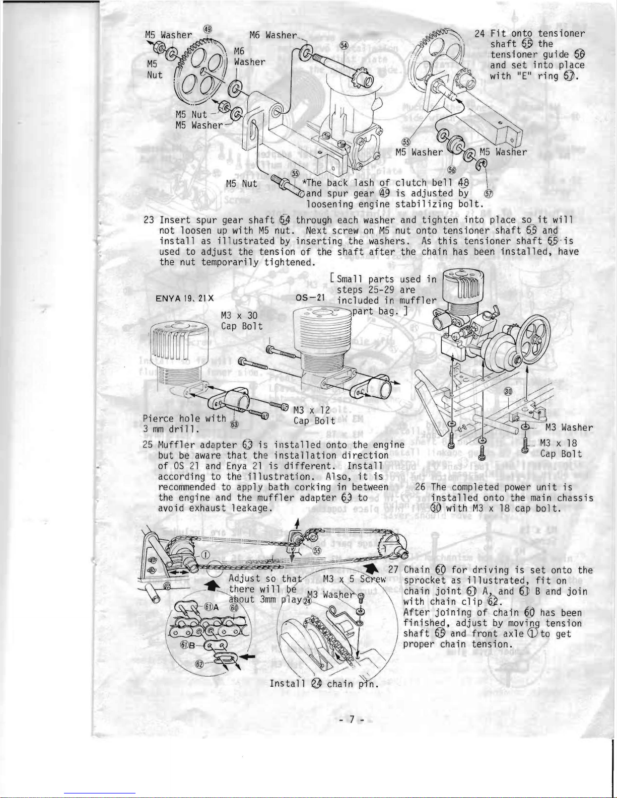
23
Insert
spur gear
shaft
~4
through each washer
and
tighten
into
place
s~
it
will
not loose,n
up
with
M5
nut.
Next
screw
on
M5
nut onto tens ioner
shaft
6.S
and
install
as
illustrated
by
inserting
the washers.
As
this
tensioner
shaft
(~'is
used
to
adjust
the tension of the
shaft
after
the chain
has
been
installed,
have
the nut temporarily
tightened.
ENYA
19,
21
X
05-21
M3 x
30
Cap
Bolt
25
~luffl
e r
adapter
Q)
is
installed
onto the engine
but
be
aware
that
the
installation
direction
of
OS
21
and
Enya
21
is
different.
Install
according to the
illustration.
Also,
it
is
recommended
to apply bath corking in between
the engine
and
the muffler adapter ~ to
avoid exhaust leakage.
h~
'.
~
~
"_~A
- @-
~
r
./"
~
'
~
.
;:~
~s~
'
~,
3
'. --:
- . . . -
..
Adjust
~o
th
_
___
~
here
wlll
a out
3mm
~
A
@W
()
0 @ @ ( 0 0
®e~
@j
-
'"
~
~
~
.
~
M3 ~5
Srn'N
e
M3
W
ar
he~@J
ay@--.....
lJ
.
~~~
Install
~
chain n.
- 7 -
~
.:
., ~~
'
~~'>->b
I
~\
\~;
'. t .
.
~
" '
''
~
~
/'
'0
'
26
The
completed
power
unit
is
installed
onto the
main
chassis
dO
with
M3 x 18
cap
bolt.
27
Chain ® for
driving
is
set
onto the
sprocket as i.
ll
ustrated,
fit
on
chain
joint
0
A"
and
6"J
B
and
join
wi
th
cha
inc
1i P '
62.
After
joining
of
chain
~O
has
been
finished,
adjust
by
moving
tension
shaft
@
a~d
fron~
axle
CD
to get
proper chaln tenSlOn.
 Loading...