

Kyosho LAMBORGHINI C-1 CAT User Manual

※ご使用前にこの説明書を良くお読みになり十分に理解してください。
Before beginning assembly, please read these instructions thoroughly!
LENGTH: 1085mm (42.7")
1:14 SCALE RADIO CONTROLLED
.21 ENGINE POWERED RACING BOAT
目 次
●キットの他にそろえる物/
●プロポの準備/
●組立て前の注意/
●本体の組立て/
●取扱いの注意/
●エンジン各部名称と働き/
●走航前のチェック/
●エンジンの始動/
●ブレークイン/
●エンジン調整/
●走航後の手入れ/
●故障?と思う前に/
●分解図/
●スペアパーツ・オプションパーツリスト/
●スペアパーツ・オプションパーツ購入方法
INDEX
REQUIRED FOR OPERATION 2
RADIO PREPARATION 3
BEFORE YOU BEGIN 3
ASSEMBLY 4~19
OPERATING YOUR MODEL SAFELY 20
ENGINE DESCRIPTION 21
CHECKLIST BEFORE RUNNING 21
ENGINE STARTING 21~22
BREAK IN 22
ENGINE ADJUSTMENT 22
MAINTENANCE 23
THE ENGINE DOES NOT START OR IMMEDIATELY STALLS 23
EXPLODED VIEW 24~25
SPARE PARTS & OPTIONAL PARTS 26
INSTRUCTION MANUAL
組立/取扱説明書
27~28
安全のための注意事項
この無線操縦模型は玩具ではありません!
●この商品は高い性能を発揮するように設計されています
ので組立てに不慣れな方は、模型を良く知っている人に
アドバイスを受け確実に組立ててください。
●
組立て作業は、幼児の手のとどかない所で行ってください
●動かして楽しむ場所は万一の事故を考えて、安全を確認
してから責任をもってお楽しみください。
●組立てた後も説明書がいつでも見られるように大切に保
管してください。
※製品改良のため、予告なく仕様を変更する場合があります。
C
2004 KYOSHO CORPORATION
/禁無断転載複製
*SPECIFICATIONS ARE SUBJECT TO BE CHANGED WITHOUT NOTICE.
。
UNDER SAFETY PRECAUTIONS
This radio control model is not a toy.
●
First-time builders should seek the advice of experienced
modellers before beginning assembly and if they do not fully
understand any part of the construction.
●
Assemble this kit only in places out of children's reach!
●
Take enough safety precautions prior to operating this model.
You are responsible for this model's assembly and safe
operation!
●
Always keep this instruction manual ready at hand for quick
reference, even after completing the assembly.
No. 41461
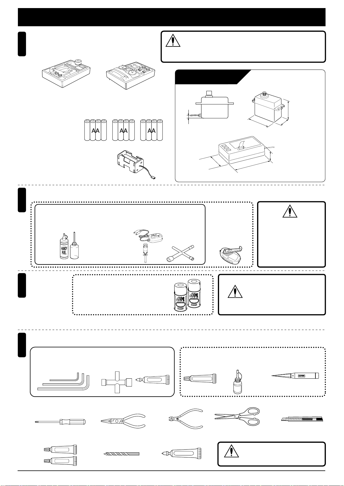
キットの他にそろえる物
REQUIRED FOR OPERATION
BEC仕様2チャンネル2サーボ仕様無線操縦機(プロポ)
2-channel radio with minimum of 2 servos.
1
■ハンドルタイプ
Wheel-type
■スティックタイプ
Stick-type
●プロポの取扱いは、プロポに付属の説明書を参考に
してください。
For more information on the radio, refer to its instruction manual.
■単3乾電池
AA-size Batteries
AA AA AA
■電池ボックス
Battery Box
●プロポセットに付いているときは
必要ありません。
If already supplied with the radio,
there is no need to purchase a battery
box separately.
燃料と始動用具
2
Required for engine starting:
水上用(ボート用)のプロポ(2チャンネル2サーボ仕様)セット
を必ず使用してください。(水上用以外使用禁止)
注意
CAUTION: Only use a surface radio with 2 channel and
2 servos !
使用できるサーボ、受信機サイズ
Servo and Receiver sizes
約3mm
Approx. 3mm
約33mm
Approx. 33mm
※
このサーボでも一部使用できない
場合があります。
Install suitably sized servos &
receiver as indicated below.
約40mm
Approx. 40mm
約47mm
Approx. 47mm
約36mm
Approx. 36mm
約20mm
Approx. 20mm
約20mm
Approx. 20mm
●エンジン始動に必要な用具をセットにしました。
No.73201
■グロー燃料、燃料ポンプ ■プラグレンチ
Glow Fuel & Fuel Pump Plug Heater / Charger
耐燃料塗料
3
Fuel-proof paint
組立てに必要な工具
4
Tools required
キットに入っている工具
TOOLS INCLUDED
■六角レンチ(1.5/2 /2.5mm)
Hex Wrench (1.5 / 2 / 2.5mm)
スーパースターターパック
Super Starter Pack
■プラグヒーター/充電器
Plug Wrench
No.695142
DC急速充電器
DC Quick Charger
No.80312
ロッキングジグ/レンチ
Lockingjig/wrench
No.695144
スパークブースター
Spark Booster
No.76301 〜 76403
京商スプレーカラー
KYOSHO SPRAY COLOR
K
O
Y
H
S
より強力な耐燃料性を必要とする場合はウレタン系塗料を使用する。
If greater fuel resistance is required, use a urethane paint.
O
S
P
O
R
L
A
O
Y
C
組立工程の中で塗料が必要です。
Paintisrequiredduringtheassemblyprocess.
■十字レンチ
Cross Wrench
■グリス
Grease
Grease
■燃料ポンプ
Fuel Pump
No.80702
F‑チャージャー
HPポンプ
F-Charger HP pump
K
O
Y
H
S
O
S
P
R
O
R
L
A
O
Y
C
R
R
R
■シリコンシール ■KYOSHO
Silicone Sealant
No.96152
SILICONE SEAL
注意
スペシャルグルー
KYOSHO Special Glue
No.96154
警告
ガソリンや灯油は
使用禁止
WARNING:
Gasoline or kerosene
cannot be used.
スプレーカラーを使用する場合、
缶の説明を良く読んでください。
CAUTION: Before using
Kyosho Spray Colors,
always read the instructions.
■ナイフエッジリーマー
KNIFE EDGE REAMER
No.695101
瞬間接着剤
Instant Glue
■+ドライバー(大、中、小)
Phillips Screwdriver (L, M, S)
■ラジオペンチ ■ニッパー
Needle Nose Pliers
■エポキシ接着剤 ■ドリル(2,3,9mm) ■ネジロック剤
Epoxy Glue Diameter drill(2,3,9mm) Screw Cement
Epoxy A
Epoxy B
2
Wire Cutters Scissors
ネジロック剤
■ハサミ
注意
KYOSHO
Special Glue
■カッターナイフ
Sharp Hobby Knife
使用する工具の取扱いには、
十分注意してください。
CAUTION: Handle tools carefully!
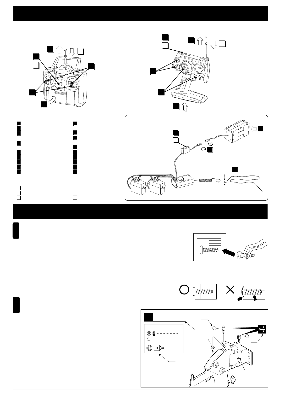
プロポの準備
RADIO PREPARATION
●プロポを下の順番にしたがってセットします。
Set up the radio as explained below.
■スティックタイプ ■ハンドルタイプ
Stick-type
ON
7
11
OFF
2
12
9
送信機
▲
Transmitter
Wheel-type
6
ON
7
11
OFF
2
12
6
送信機
▲
Transmitter
9
1
●始める時
1
送信機に単3乾電池をセットする。
2
送信 機の アン テナ をの ばす。
3
電池ボックスに単3乾電池を
セットする。
電池 ボッ クス のコ ネク ター
4
をつなぐ。
受信 機の アン テナ をの ばす。
5
トリ ムを 中央 にセ ット する。
6
送信 機の スイ ッチ を入 れる。
7
8
受信 機の スイ ッチ を入 れる。
9
ハンドル/ト リガーを動かし
てサーボが動いているか確認。
●終わる時
10
受信機のスイッチを切る。
11
送信機のスイッチを切る。
12
送信 機の アン テナ を縮 める。
●START
1
Insert AA-size batteries into
the Transmitter.
2
Extend the Transmitter antenna.
3
Insert the AA-size batteries
into the battery box.
4
Plug in the battery box.
Unwind the Receiver
5
Center the Transmitter trims.
6
Switch "ON" the Transmitter.
7
8
Switch "ON" the Receiver.
9
Make sure the servos move according to your transmitter inputs.
●FINISH
10
Switch "OFF" the Receiver.
11
Switch "OFF" the Transmitter.
12
Retract the Transmitter antenna.
antenna.
▲
サーボ
Servo
組立て前の注意
BEFORE YOU BEGIN
組立ての前に下記のことに注意してください。
1
Before assembling, please read the following carefully:
●この説明書を良く読み、構造を理解する。
First, read through this instruction manual and understand the modelÕs con-struction.
●小さな部品の形やサイズを間違えないようにする。図を参考にして確認しながら組立てる。
Do not use the wrong size or shaped small parts. Check the illustrations & use the correct
part for each step of assembly.
●キットの内容を確かめる。
※万一不良、不足がありましたら、お買い求めの販売店か、当社「ユーザー相談室」までご連絡ください。
Check the contents of this kit. Should parts be missing, immediately contact the retail shop or your nearest Kyosho distributor.
●TPビス締をめるときは・・・
締めこみが固くても部品が固定されるまで締めてください。ただし、部品が変形するまで締めるとビスがきかなくなります。
When tightening a self-tapping (TP) screw: continue tightening until fastened correctly,
even if screw is hard to turn.
However, do not overtighten it as the plastic thread inside the part may strip!
説明書の見かた
2
How to read the instruction manual:
A:
この項目で組立てるおおよその場所。
B:
小物部品の名前、原寸図、使用数。
C:
キット内の部品は、ビス類を除いてキーNo.が付けられています。
スペアパーツを
D:
説明書内では多くのマークが使用されています。
マークに注意して組立てを進めてください。マークの説明は、
各ページの下にあります。
A: Indicates the assembly step number and the section that will
be assembled.
B: Key Number, Part Name, True-to-scale Diagram, Quantity Used.
C: All parts except screws are identified by key numbers.
For purchasing spare parts, find the key number of the part
needed in the spare parts list and refer to the left column to
look up the corresponding order number.
D: This instruction manual uses several symbols.
Please note them during the entire assembly at the bottom of
each page.
購入する時はキーNo.を参照してください。
説明例
〔Example〕
ラダー
Rudder
14
2mm
ナイロンナット
Nylon Nut
31
リンケージポスト
Linkage Post
B
1
8
ON
10
OFF
Correct
2
2
▲スイッチ
Switch
▲受信機
Receiver
A
C
2mm
3
4
▲電池ボックス
Battery Box
5
Wrong
31
31
D
2mm
3
メカボックス
Radio Box
1
9mm
1
2
3
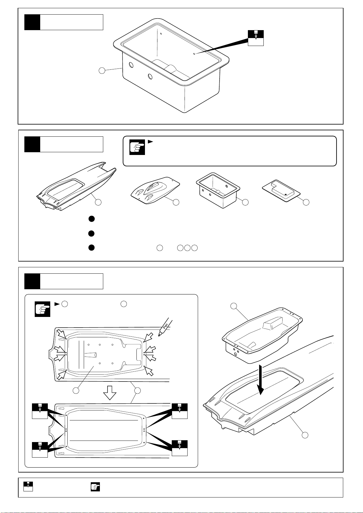
塗装
Painting
船体
Hull
ABS樹脂製品はグロー燃料に侵され
内側、外側を必ず耐グロー燃料塗料を厚めに塗装する。
Coat the hull's interior and exterior surfaces with glow fuel-resistant coating
as the shape of the ABS resin material may change if soaked in glow fuel.
4
塗装前に、中性洗剤で油やよごれを洗う。
1
Before painting, remove any dirt or oil by washing with mild detergent.
水分を完全に乾かす。
2
Completely dry the surfaces to be painted.
3
耐燃料用塗料で塗装する。
Coat in fuel-resistant paint. Also paint parts 1, 2, & 3 that fit inside the hull (4).
5 4
の矢印の穴に合わせて に油性ペンで印をつける。
Make pen marks on 4 through the holes in 5 as per the arrows.
3 1 2
4
1 2 3
の中、 の裏側も同様に塗装する。
ると変質やひび割れするので、船体の
5
2mm
9mmの穴をあける(例)。
Drill holes with the specified
9
mm
diameter.
4
注意して組立てる所。
Pay close attention
here!
45
2mm2mm
4
2mm
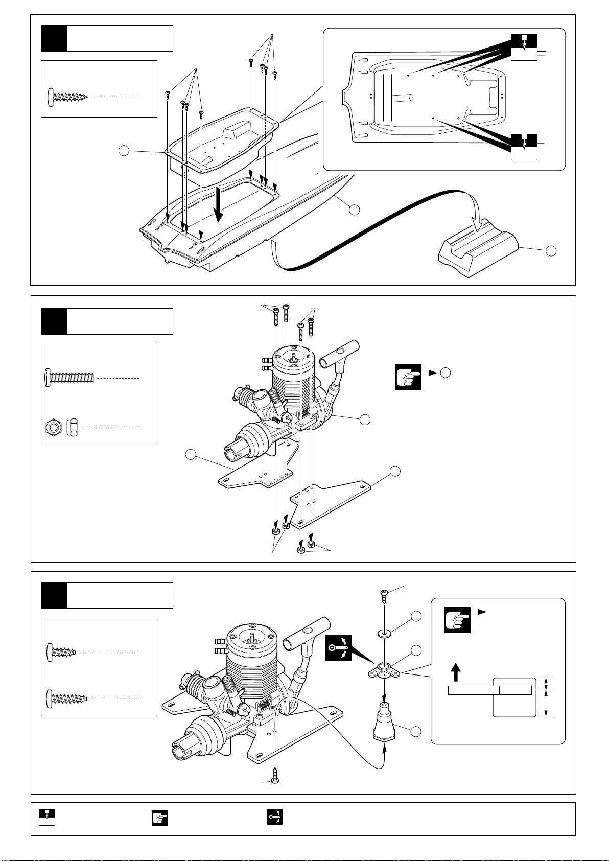
船体
Hull
4
2.6x 12mm
TP Screw
TPビス
2.6x12mm
2.6x12mm
8
3mm
エンジンマウント
Engine Mount
5
3 x 15mm
Screw
3mm
Nut
ビス
ナイロンナット
5
3mm
4
67
3x15mm3x15mm
7
4
の向きと穴位置に注意。
Check direction of 7 and
position of holes.
6
4
エンジンマウント
Engine Mount
6
3 x 8mm
TP Screw
3 x 12mm
TP Screw
TPビス
TPビス
7
7
3mm 3mm
3 x 8mm
8
1
1
9
10
向きに注意。
Note the direction.
上
Top
短
Short
長
Long
9mmの穴をあける(例)。
Drill holes with the specified
9
mm
diameter.
注意して組立てる所。
Pay close attention
here!
3 x 12mm
可動するように組立てる。
Ensure smooth non-binding
movement while assembling.
5
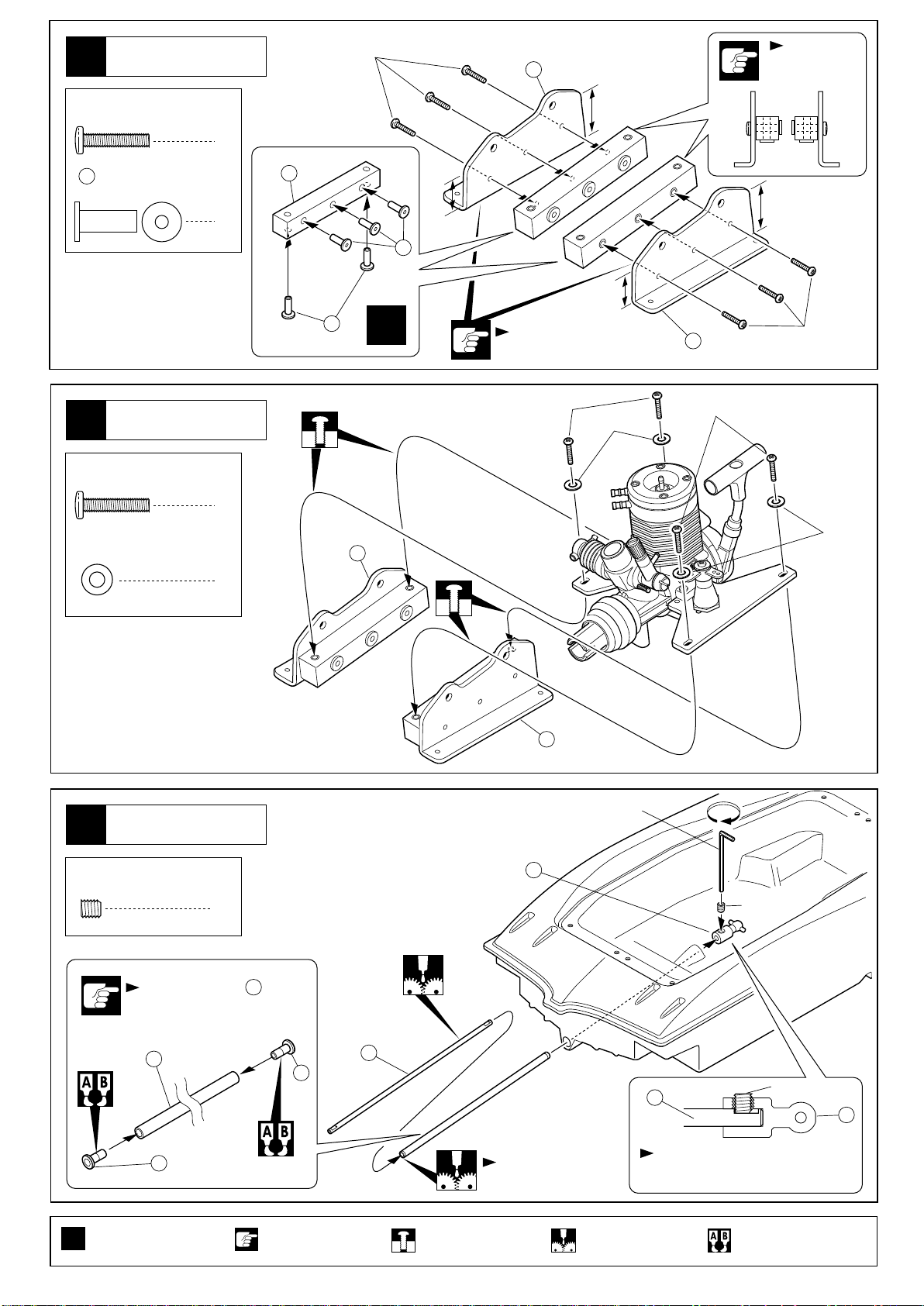
エンジンマウント
Engine Mount
7
3 x 15mm
Screw
ビス
3 x 15mm
14
高
High
6
向きに注意。
Note the
direction.
マウントカラー
11
Mount collar
エンジンマウント
Engine Mount
8
3 x 15mm
Screw
3mm
Washer
ビス
ワッシャー
10
12
高
低
Low
High
11
3mm
低
Low
3 x 15mm
13
3 x 15mm
3mm
11
x2
4
向きに注意。
Note the direction.
3 x 15mm
14
4
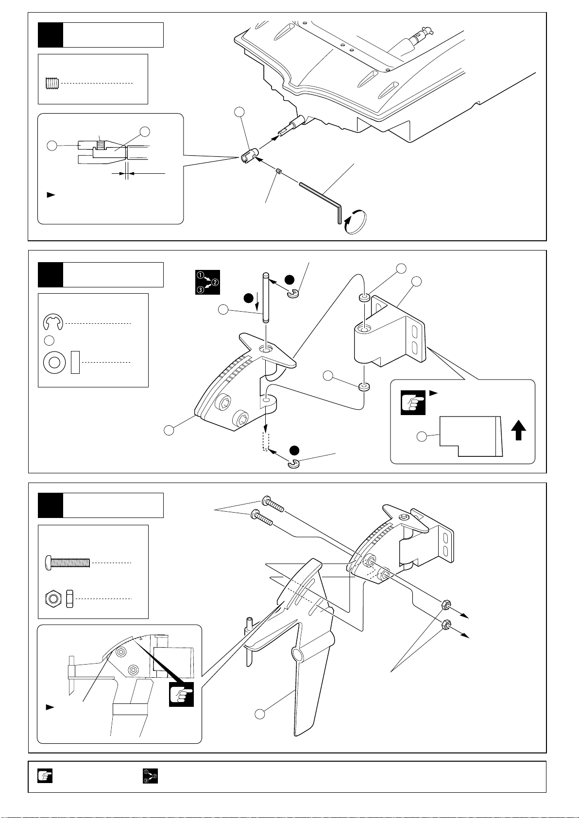
ドライブシャフト
9
Drive Shaft
4 x 4mm
Set Screw
セットビス
エポキシ接着剤が の穴に
入らない様、注意する。
Make sure epoxy glue does
NOT enter holes on 15.
16
15
13
六角レンチ(2.0mm)
Hex Wrench (2.0mm)
18
1
4 x 4mm
15
17
15
17
4 x 4mm
18
グリスを多めに入れる。
Apply plenty of grease.
平らな面にセットビスを固定する。
Firmly tighten the set screw onto
the flat spot.
x2
6
2セット組立てる(例)。
Assemble as many times
as specified.
注意して組立てる所。
Pay close attention
here!
仮止め。
Tentatively tighten.
グリスを塗る。
Apply grease.
エポキシ接着剤で接着する。
Apply epoxy glue.
ドライブシャフト
Drive Shaft
10
4 x 4mm
Set Screw
セットビス
4x4mm
19
平らな面にセットビスを固定する。
Firmly tighten the set screw onto
the flat spot.
ラダー
Rudder
11
E3
Eリング
E-ring
23
4 x 8mm
Metal Bushing
メタル
1
17
0.5mm
2
2
22
19
2
4x4mm
1
E3Eリング
E-ring
23
六角レンチ(2.0mm)
Hex Wrench (2.0mm)
23
20
ラダー
Rudder
12
3 x 14mm
Screw
3mm
Nut
ビス
ナット
向きに注意。
Note the direction.
21
3
3x14mm
2
2
E3Eリング
E-ring
20
上
Top
すき間をあけない
Make sure that
there is no gap.
注意して組立てる所。
Pay close attention
here!
3mm
。
番号の順に組立てる。
Assemble in the
specified order.
24
7

ラダー
Rudder
13
4 x 8 x 3mm
25
4 x 9 x 4mm
27
Collar
4 x 4mm
Set Screw
セットビス
向きに注意。
Note the direction.
短い
Short
30 29 28 27
ステンレスベアリング
Stainless Bearing
2
カラー
1
2
長い
Long
六角レンチ(2.0mm)
Hex Wrench (2.0mm)
26
4 x 4mm
25
25
27
28
29
30
平らな面にセットビスを固定する。
Firmly tighten the set screw onto the flat spot.
0.5mm
ラダー
Rudder
14
2mm
Nylon Nut
ナイロンナット
31
リンケージポスト
Linkage Post
ラダー
Rudder
15
3 x 12mm
TP Screw
TPビス
31
2mm
2
2
4
3x12mm
31
2mm
8
注意して組立てる所。
Pay close attention
here!
3x12mm
可動するように組立てる。
Ensure smooth non-binding
movement while assembling.
仮止め。
Tentatively tighten.
 Loading...