

Page 1

※ご使用前にこの説明書を良くお読みになり十分に理解してください。
Before beginning assembly, please read these instructions thoroughly.
R
組立/取扱説明書
THE FINEST RADIO CONTROL MODELS
INSTRUCTION MANUAL
1/10スケール12‑15エンジンラジオコントロール2WDスタジアムトラック
GPアルティマSTType‑Rエボリューション
目 次 INDEX
●キットの他にそろえる物 REQUIRED FOR OPERATION
●プロポの準備 RADIO PREPARATION
●組立て前の注意 BEFORE YOU BEGIN
●ランナー付プラパーツ配置図 ARRANGEMENT OF PLASTIC PARTS ON RUNNERS
●本体の組立て ASSEMBLY
●取扱いの注意 OPERATING YOUR MODEL SAFELY
●分解図 EXPLODED VIEW
●スペアパーツ・オプションパーツリスト SPARE PARTS & OPTIONAL PARTS
安全のための注意事項
●この商品は高い性能を発揮するように設計されています。
組立てに不慣れな方は、模型を良く知っている人にアド
バイスを受け確実に組立ててください。
●小さい部品があるので、組立て作業は、幼児の手がとど
かない所で必ず行ってください。
●動かして楽しむ場所は万一の事故を考えて、安全を確認
してから責任をもってお楽しみください。
●組立てた後も、説明書がいつでも見られるように大切に
保管してください。
※製品改良のため、予告なく仕様を変更する場合があります。
© 2003 KYOSHO CORPORATION/禁無断転載複製
SPECIFICATIONS ARE SUBJECT TO BE CHANGED WITHOUT NOTICE.
●First-time builders should seek the advice of experienced modellers
before beginning assembly and if they do not fully understand any
part of the construction.
●Assemble this kit only in places out of children's reach!
●Take enough safety precautions prior to operating this model.
You are responsible for this model's assembly and safe operation!
●Always keep this instruction manual ready at hand for quick
reference, even after completing the assembly.
UNDER SAFETY PRECAUTIONS
This radio control model is not a toy.この無線操縦模型は玩具ではありません!
(国内仕様)
2〜3
3
4〜5
5
6〜28
29
30〜31
32〜35
No.31973
Page 2
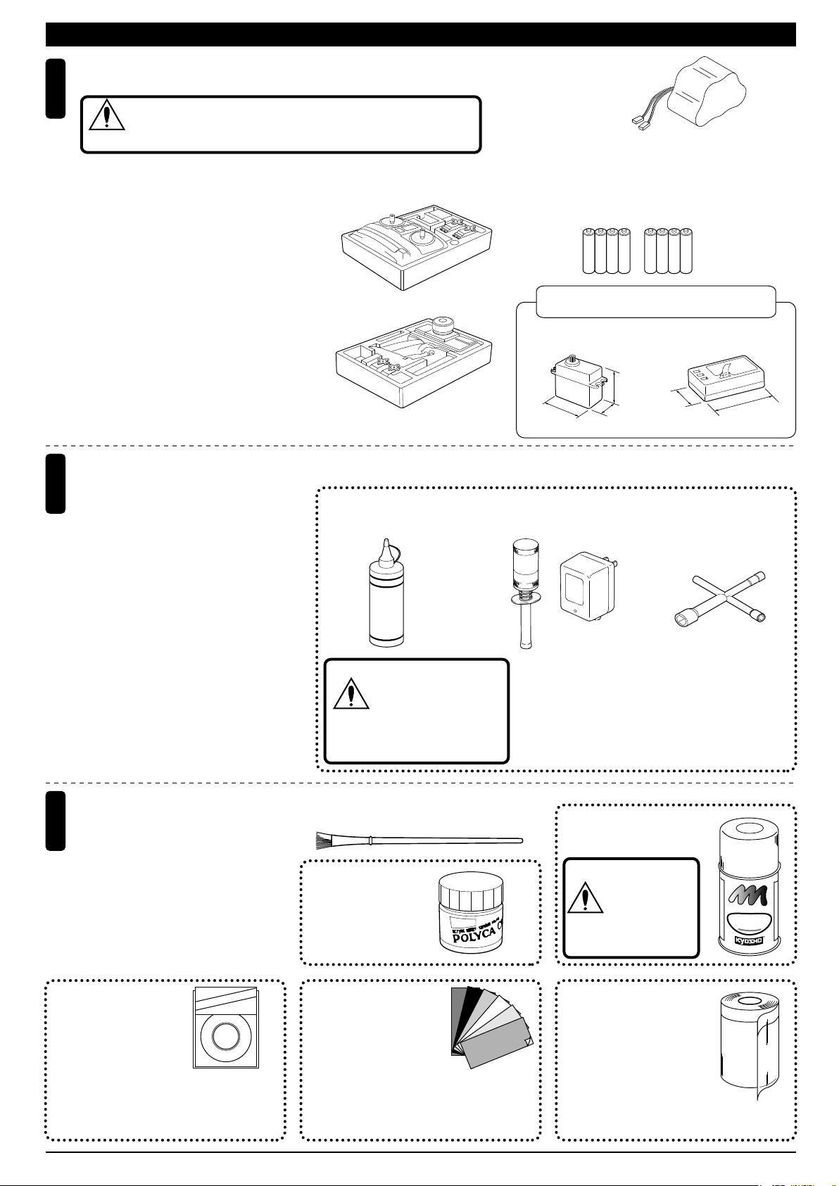
REQUIRED FOR OPERATION (1)キットの他にそろえる物(1)
2チャンネル2サーボ無線操縦機(プロポ)と電池ボックス
Minimum 2 channel radio with 2 servos, and battery box.
1
地上用(自動車用)のプロポ(2チャンネル2サーボ仕様)セットを
必ず使用してください。(地上用以外使用禁止)
CAUTION: Only use a surface radio with 2 channels and 2 servos!
注意
●送信機にはスティックタイプとハン
ドルタイプがあ りま すが、お好みの
タイプを用意してください。
●リバーススイッチはステアリングサ
■スティックタイプ
Stick-type
2ch radio.
ーボ、スロット ルサ ーボ共にノーマ
ルで使用します。
●プロポの取扱いは、プロポに付属の
説明書を参考にしてください。
●Because there are stick-type and
wheel-type transmitters, use which
ever fits your convenience best.
●Switch the reverse (transmitter) for
■ハンドルタイプ
Wheel-type
2ch radio.
the steer-ing and throttle control.
●For more information on the radio,
refer to its instruction manual.
燃料と始動用具
2
Required for engine starting:
●模型用エンジンは専用のグロー燃料が必
要です。ガソリンや灯油は使用できませ
んので注意してください。また、グロー
燃料は揮発性が高く引火しやすいので取
扱いには充分注意してください。
●エンジン始動にはその他に、プラグを赤
熱させるプラグヒーター(ブースターコ
ード+乾電池)、プラグを脱着するプラ
グレンチが必要です。
●Engines for R/C models require glow fuel.
Be careful not to purchase gasoline or
kerosene by mistake; both cannot be
used! Also, be very careful when han-dling glow fuel which is hi-ghly inflamma-ble and high-explosive!
●Besides glow fuel, engines also require
engine starting equipment. This comprises a glow plug heater (booster cord &
batteries) and a plug wrench for removing and installing the glow plug.
■グロー燃料
Glow Fuel
警告
FUEL
ガソリンや灯油は
使用禁止
WARNING: Gasoline
or kerosene cannot
be used.
■受信機用ニカドバッテリー
Ni-Cd Battery
※No.711616VX‑FORCE600ニカドバッテ
リーを必ず使用してください。
Only use No.71161 6V X-FOURCE 600 Ni-Cd
Battery. (Do not use other batteries.)
■単3乾電池
AA-size Batteries
AAAA
AAAA
使用できるサーボ・受信機サイズ
Suitable servos & receiver
■サーボ
Servo
31〜36mm
38〜41mm
18〜20mm
■プラグヒーター/充電器
Plug Heater / AC Charger
●エンジン始動に必要な用具セット
No.73201
スーパースターターパック
Super Starter Pack
29〜32mm
■受信機
Receiver
43〜48mm
■プラグレンチ
Plug Wrench
塗料と筆
3
Paint and Brush
●ボディの塗装には塗料が必要です。
京商ではモデル 用塗 料、スプレーを
用意していますのでご利用ください。
●For painting the body, use Kyosho
paints for models!
No.1841
1842
1843
1859
1860
(1mm x 5m)
(1.5mm x 5m)
(2.5mm x 5m)
(0.4mm x 8m)
(0.7mm x 8m)
Tape
ne
Li
on
cr
Mi
KYOSHO
ミクロンラインテープ
MICRON LINE TAPE
マスキング、細部デザイン用伸縮自在テープです。
Super-flexible tape for masking and detail designing
jobs.
2
■筆
PAINT BRUSH
No.2230
ポリカカラー
POLYCA COLOR
No.96701〜96703
D-フレックスカラーデカール
D FLEX COLOR DECAL
伸縮自在の特殊素材で3次曲面
にもきれいに貼れる粘着シートです。
Self-adhesive super-flexible sheets that
bond to polycarbonate - even when
applied to curved surfaces.
No.76301〜76711
京商スプレーカラー
KYOSHO SPRAY COLOR
スプレーカラーを
使用する場合、缶
の説明を良く読ん
注意
でください。
CAUTION: Before
using spray colors,
always read their
explanations!
F
U
E
L
P
R
O
F
P
F
K
Y
H
S
O
S
P
R
A
O
Y
C
No.1947
マスキングカバーシート
MASKING SHEET
マスキングテープとビニール
シートが一体になった広範囲
マスク用テープです。
For safe masking jobs, use this plastic masking
sheet featuring one self-adhesive edge.
T
N
I
A
O
R
O
L
R
Page 3
REQUIRED FOR OPERATION (2)キットの他にそろえる物(2)
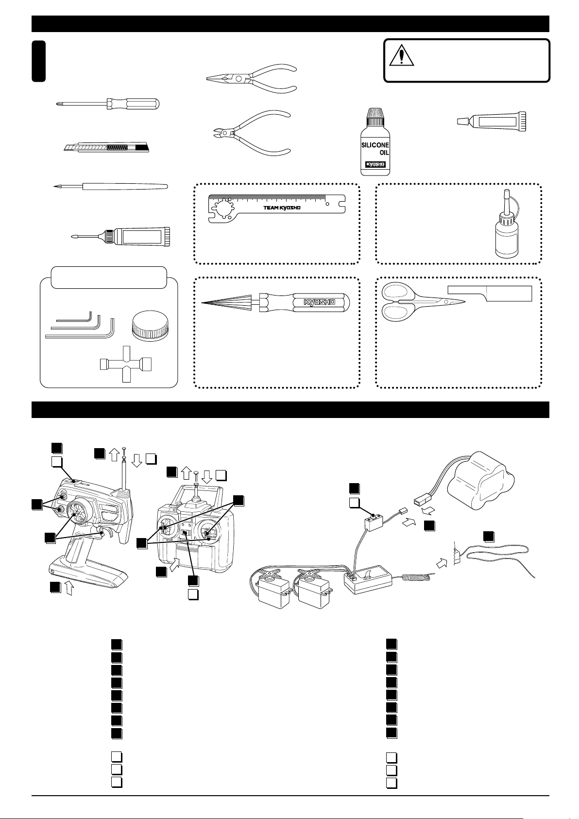
組立てに必要な工具
Tools required
4
■+ドライバー(大、中、小)
Phillips Screwdriver ( L. M. S. )
■カッターナイフ
Sharp Hobby Knife
■キリ
Awl
■モリブデン系グリス
Molybdenum Grease
キットに入っている工具
TOOLS INCLUDED
■六角レンチ
Hex Wrench
■十字レンチ
Cross Wrench
Grease
■ボールデフグリス
All Differential Grease
■ラジオペンチ
Needle Nose Pliers
■ニッパー
Wire Cutters
50
No.80951B
フライホイールレンチ
Flywheel Wrench
No.80311
スペシャルテーパーリーマー
SPECIAL TAPER REAMER
下穴加工が不要で、直接
1mm〜15mmの正確な穴
あけができる工具です。
■ダンパー用シリコンオイル
Silicone Oil (for Shock)
mm
100
No.80951B
No need to pre-drill!
Drills neat 1mm to 15mm
holes directly!
使用する工具の取扱いには、充分
注意してください。
CAUTION: Handle tools carefully!
注意
■ゴム系接着剤
Rubber Cement
No.96154
KYOSHO スペシャルグルー
KYOSHO Special Glue
瞬間接着剤
Instant Glue
No.1829
ラウンドカッター&サンダー
ROUND CUTTER & SANDER
ボディのカット、仕上
げ用。曲線部分も楽に
作業ができます。
For trimming bodies!
Cutting along curved lines
never was so easy!
ゴム系接着剤
KYOSHO
Special Glue
ON
6
10
2
OFF
5
8
1
●始める時
プロポの準備 RADIO PREPARATION
●プロポを下の順序にしたがってセットします。
Set up the radio control system as indicated below.
11
2
5
1
1
単3乾電池をセットする。(送信機)
アンテナをのばす。(送信機)
2
ニカドバッテリーをつなぐ。
3
アンテナをのばす。(受信機)
4
トリムレバーを中央にセットする。
5
スイッチを入れる。(送信機)
6
スイッチを入れる。(受信機)
7
スティックを動かしてサーボが動くか確認する。
8
6
10
ON
OFF
11
8
送信機
▲
Transmitter
▲サーボ
Servo
ON
7
9
OFF
▲スイッチ
Switch
●START
▲バッテリー
Battery
3
4
▲受信機
Receiver
Install batteries. (Transmitter)
1
Extend the antenna. (Transmitter)
2
Connect the Ni-Cd battery.
3
Extend the antenna. (Receiver)
4
Center the trims.
5
Switch on. (Transmitter)
6
Switch on. (Receiver)
7
Make sure the servos are in command.
8
●終わる時
9
スイッチを切る。(受信機)
10
スイッチを切る。(送信機)
11
アンテナを縮める。(送信機)
●FINISH
Switch off. (Receiver)
9
Switch off. (Transmitter)
10
Retract the antenna. (Transmitter)
11
3
Page 4

組立て前の注意(1) BEFORE YOU BEGIN (1)
組立てる前に説明書を良く読んで、おおよその構造を理解してから組立てに入ってください。
1
Read through the manual before you begin, so you will have an overall idea of what to do.
キットの内容をお確かめください。万一不良、不足がありましたら、お買い求めの販売店にご相談いただくか、当社「ユーザー相談室」までご連絡ください。
2
Check all parts. If you find any defective or missing parts, contact your local dealer or our Kyosho Distributor.
説明書の見かた
3
How to read the instruction manual:
〔説明例Example〕
説明書内では多くのマークが使用
フロントサスペンション
Front Suspension
1
4
5 x 10mm メタル
Metal Bushing
No.4, No.5, No.6
1
されています。マークに注意して
組立てを進めてください。
This instruction manual uses several symbols. Please note them
during the entire assembly.
4
キングピン
5
King Pin
4
5.8mm ピロボール(黒)
6
Pillow Ball (Black)
2
小物部品の名前、原寸図、使用数。
Key Number, Part Name, True-to-scale
Diagram, Quantity Used
説明書に使われているマーク
4
Symbols used throughout the instruction manual, comprise:
使用する袋詰。
Part bags used.
キット内の部品は、ビス類を除いてキー
No.が付けられています。スペアパーツを
購入する時はキーNo.を参照して下さい。
All parts except screws are identified by
key numbers. For purchasing spare parts,
find the key no. of the part needed in the
spare part list and refer to the left column
to look up the corresponding order no.
4
2mm
3
6
2mmの穴をあける(例)。
Drill holes with the specified
diameter (here: 2mm).
5
7
R
L
5
8
番号の順に組立てる。
Assemble in the specified
order.
2
x2
ゴム系接着剤で接着する。
Apply rubber cement.
グリスを塗る。
Apply grease.
ネジロック剤を塗る。
Apply threadlocker (screw cement).
2セット組立てる(例)。
Assemble as many times as
specified (here: twice).
左右同じように組立てる。
Assemble left and right sides
the same way.
余分をカットする。
Cut off excess.
をカットする。
Cut off shaded portion.
仮止め。
Tentatively tighten.
可動するように組立てる。
Ensure smooth non-binding
movement while assembling.
原寸図
True-to-scale diagram.
別購入品
Must be purchased separately!
注意して組立てる所。
Pay close attention here!
4
Page 5

組立て前の注意(2) BEFORE YOU BEGIN (2)
キットには、形や長さが違うビスや小物部品が多く入っています。説明書には原寸図がありますので確認してから組立ててください。
5
また、ビス類は多めに入っているものもありますので、予備としてお使いください。
This kit contains screws and hardware in different metric sizes and shapes.
Before using them, check the screws on the true-to-scale diagrams on the left side in each assembly step. Some screws are extras.
●ビスの種類 SCREWS
ビス Screw
キャップビス
Cap Screw
サラビス
Flat Head (F/H) Screw
TPビスは、部品にネジを切りながらしめつけるビスです。しめこみが固い場合がありますが、
6
部品が確実に固定されるまでしめこんでください。ただし、しめすぎるとネジがきかなくなり
ますので、部品が変形するまでしめないでください。
Self-tapping (TP) screws cut threads into the parts when being tightened. Excessive force may
permanently damage parts when tightening TP screws. It is recommended to stop tightening when
the part is attached or when some resistance is felt after the threaded portion enters the plastic.
TPビス
Self-tapping (TP) Screw
TPサラビス
TP F/H Screw
セットビス
Set Screw
●小物部品のサイズ例 OTHER HARDWARE
3x12mmビス
Screw
12mm
3x12mmサラビス
F/H Screw
3mm
12mm
3mmワッシャー・ナット
Washer・Nut
3mm
5x10mmメタル・ベアリング
Metal Bushing・Bearing
5mm
10mm
ランナー付プラパーツ配置図 ARRANGEMENT OF PLASTIC PARTS ON RUNNERS
28
26 26
2727
2828
SFH
3mm
22 22 22
E3Eリング
E-ring
3mm
6.8mmピロボール
Pillow Ball
6.8mm
Correct
Wrong
しめすぎ
Overtightened.
部分の部品は、使用しません。
Shaded Parts are not used.
ビスがきかない
The threads are stripped.
21 21 21
20 20
29
23
6
R
3 B 3 B
A
3
C
2
79 79
80
80
2 B
8 7
81 81
81 81
24
80
80
2 B
25
22 22 22
21 21 21
10
10
13 12
5
L
9 9
20 20
30
31
161
3
A
C
2
8787
260
164 164
262
5
Page 6
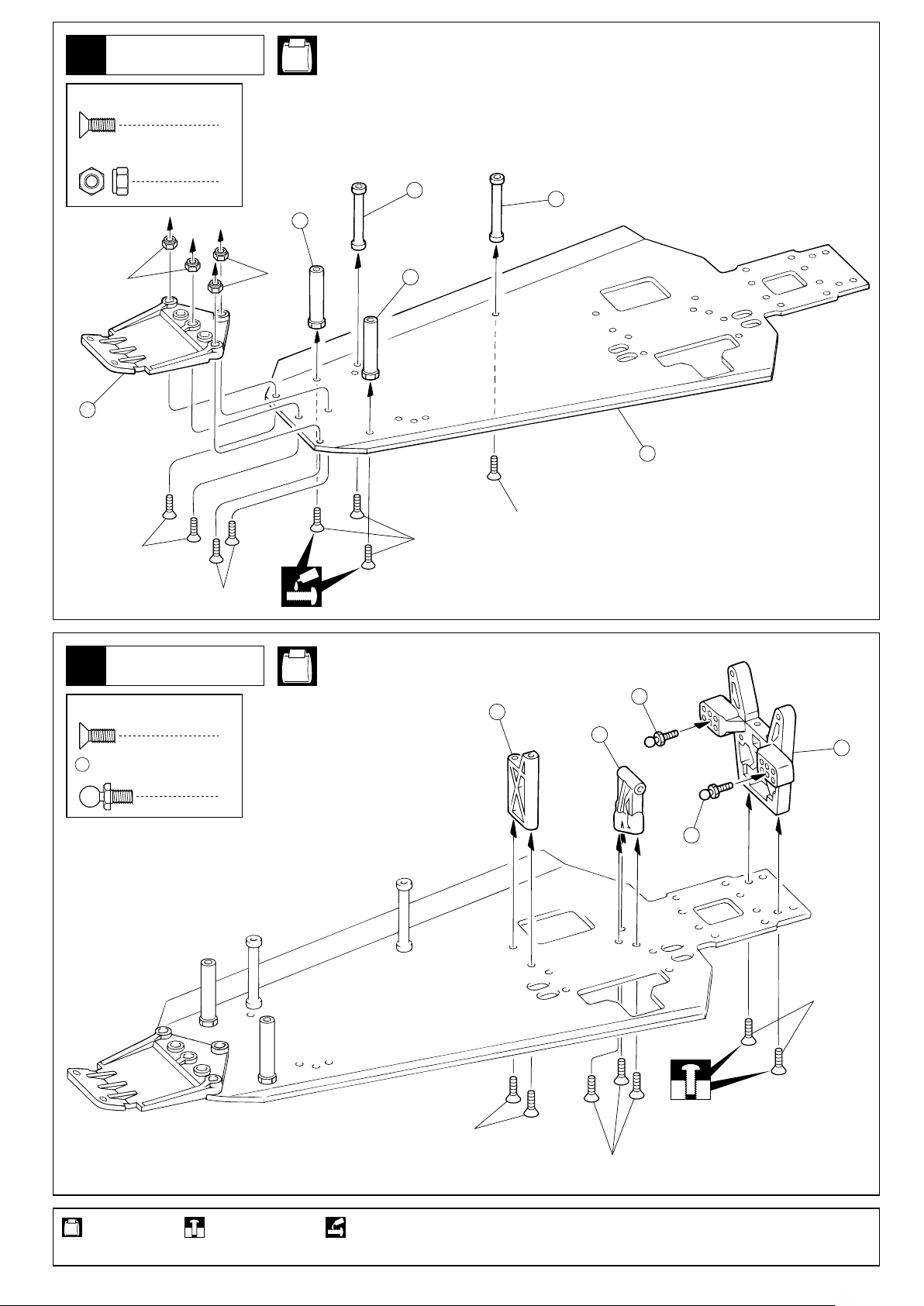
1
シャシー
Chassis
No.2, No.4, No.7
3 x 8mm
F/H Cap Screw
3mm
Nylon Nut
サラキャップビス
ナイロンナット
3mm
15
3x8mm(F/H)
8
4
139
139
145
3mm
145
201
3x8mm(F/H)
3x8mm(F/H)
3x8mm(F/H)
リヤギヤボックス
Rear Gearbox
2
3 x 8mm
F/H Cap Screw
59
サラキャップビス
4.8mm
ボールスタッド(S)
Ball Stud (S)
No.2, No.3
59
203
7
204
205
2
59
3x8mm(F/H)
使用する袋詰。 仮止め。
Part bags used.
6
Tentatively tighten.
3x8mm(F/H)
3x8mm(F/H)
ネジロック剤を塗る。
Apply threadlocker (screw cement).
Page 7
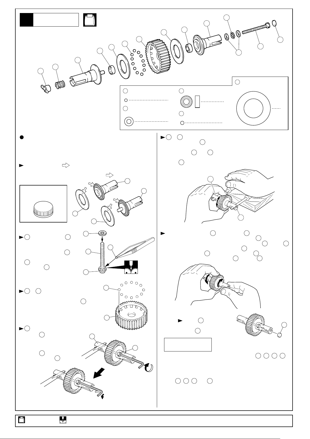
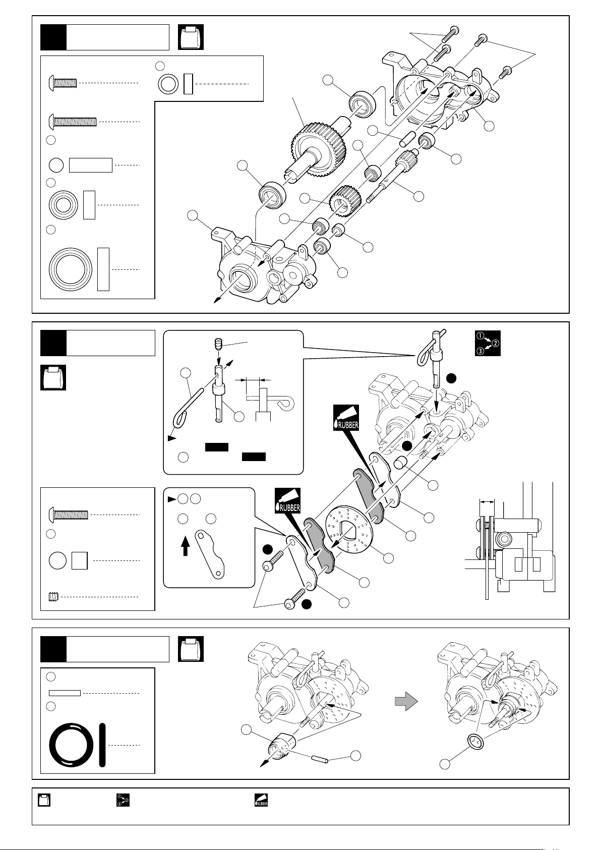
デフギヤ
Gear Differential
3
分解図
EXPLODED VIEW
45
40
34
No.1
50
< >ボールデフユニット
< >Ball Diff unit
36
206
37
55
1/16
スラストボール
Thrust Ball
54
スラストワッシャー
Thrust Washer
37
50
50
4 x 8mm
Ball Bearing
8
206
3/32
Thrust Ball
2
35
ベアリング
スラストボール
12
55
54
37
2
41
39
スラストプレート
Thrust Plate
2
組立ては上の分解図を参考にしてください。
下記の点に注意してください。
Assemble with the aid of the above exploded view and pay
attention to the following.
油分をとり(脱脂)、 の所にボールデフグリスを少し塗る。
Remove oil deposits from before applying a small amount of ball
differential grease to the spots marked with .
35
ボールデフグリス
Ball Differential Grease
37
37
はグリスを塗った に
55
8個並べる。
After applying Grease, place
eight differential balls between the two thrust washers
, grouping them around
54
the screw .
39
54
55
54
55
39
54
を に組込み、ボールデフ
206
36
グリスを塗る。
Place the differential balls into
and apply ball differential grease.
206
206
34
と をマイナスドライバーで固定し、本体を回してみる。
34 35
回らなくなるまで をしめ込む。回ってしまう状態のまま走行
させると破損するので注意。
Secure parts and in place with two flat head screwdrivers
and rotate the differential case until it becomes tight. Then, tighten
screw . When running the car, the differential must be tight,
39
otherwise it may be damaged.
34
39
35
34
35
次に本体を手で固定し、 を回したとき、 が反対方向に回転す
れば良い。回らないときはしめ込み過ぎなので、 をゆるめる。
Now, hold the differential case firmly and rotate part . If part
rotates into the opposite direction to part , no further adjustment
is necessary. If part does not rotate, screw is too tight.
In this case, gradually loosen screw until part rotates.
36
35
39
36
39
35 36
35
39
36
をマイナスドライバーで
34
固定し、 をいっぱいにしめ
込み、それから1/8回転ゆるめる。
(後で調整する)
Tighten with a screwdriver
and fully tighten then rewind
1/8 turn.
(Adjust it later)
39
34
39
使用する袋詰。 グリスを塗る。
Part bags used. Apply grease.
34
36
39
調整後、 を取付ける。
Once the adjustment is done,
install (see"exploded view").
41
41
41
メンテナンス
MAINTENANCE
作動させたときになめらかに動かなくなったら、 , , ,
が汚れています。分解して掃除してください。それでも直らない
ときは、これらのパーツが消耗しているので交換してください。
また、これらのパーツは定期的に交換するとよいでしょう。
As soon as the ball differential's smooth action becomes rough,
parts , , and may have become "gritty". If this
37
206
happens, disassemble the unit and clean these parts, apply more
grease and reassemble. If the action is still not smooth, the parts
are worn and, therefore, must be replaced. We recommend that
these parts be replaced from time to time to ensure smooth running.
54 55
37
206
54 55
7
Page 8
リヤギヤボックス
Rear Gearbox
4
3 x 8mm
Button Cap Screw
3 x 15mm
Button Cap Screw
49
51
52
ボタンキャップビス
ボタンキャップビス
5 x 15mm
Shaft
5 x 10mm
Ball Bearing
10 x 15mm
Ball Bearing
シャフト
ベアリング
ベアリング
2
2
1
4
70
5 x 7 x 3mm
No.1
アルミカラー
Aluminium Collar
141
52
1
デフギヤ
Differential
143
51
52
51
49
70
3x15mm
3x8mm
140
51
207
ブレーキ
Brake
5
No.1
3 x 12mm
138
3 x 3mm
Set Screw
ボタンキャップビス
Button Cap Screw
ブレーキカム
Brake Cam
セットビス
2
3x3mm
137
5mm
51
1
208
スライドキャブ式エンジンを使用する
場合は、
42‑4
is attached at
137
using the slide carburetor engine.
は向きに注意。
134 135
2
Note the direction for
and .
134
で取付けます。
42-4 only when
135
2
138
約6mm
approx. 6mm
134
135
3
1
上
Top
133
134
1
3x12mm
3
135
メインギヤ
Main Gear
6
2 x 11mm
71
Shaft
210
Oリング
O-ring
シャフト
1
No.1
209
1
使用する袋詰。 番号の順に組立てる。 ゴム系接着剤で接着する。
Part bags used.
Assemble in the specified order. Apply rubber type glue.
8
71
210
Page 9
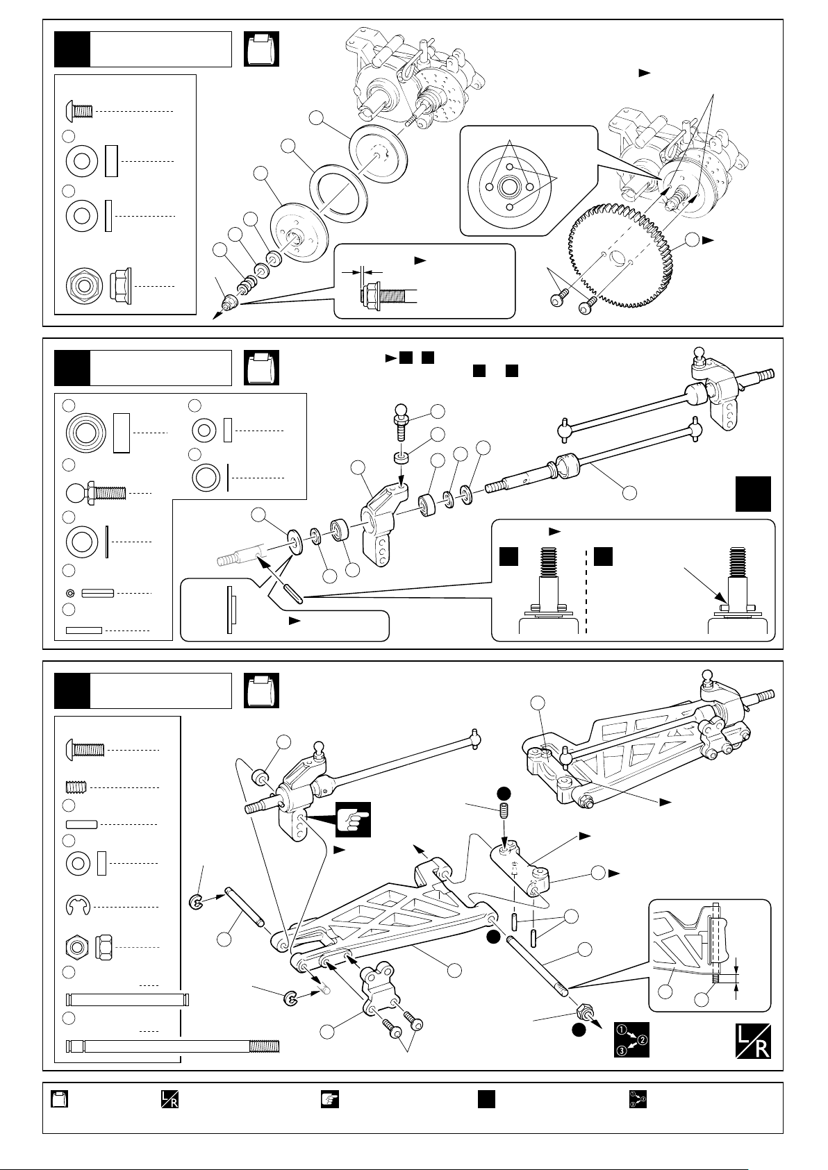
メインギヤ
Main Gear
7
3 x 5mm
Button Cap Screw
21214 x 8mm
ボタンキャップビス
スラストブッシュ
Thrust Bushing
No.1
3mmビス穴にねじ込む。
Tighten 3mm screws.
2
42
3mm
211
213
4 x 8mm
Thrust Plate
4mm
Flanged Nylon
スラストプレート
フランジ付ナイロンナット
リヤサスペンション
Rear Suspension
8
51
5 x 10mm
Ball Bearing
58
4.8mm
Ball Stud (L)
73
5 x 8 x 0.5mm
Shim
74
1.5 x 8mm
Roll Pin
21821.6 x 9mm
Pin
ベアリング
ボールスタッド(L)
シム
ロールピン
ピン
43
1
212
213
214
4mm
1
No.3, No.4
3 x 6 x 2mm
10
Plastic Collar
4
5 x 7 x 0.1mm
216
Shim
2
プラカラー
2
シム
4
0.2mm
< Left > < Right >
左側用 右側用
シャフトの面から
1/2回転しめる。
Tighten 1/2 turn
from the edge.
, の2通りの組み立てが出来ます。BA
Choose either or .A B
58
10
73
216
9
51
217
2
A
51
216
2
内側外側
InsideOutside
向きに注意。
Note the direction.
3x5mm
2.6mm
均等に入れる。
ゴム系接着剤等
B
で固定する。
Apply rubber
cement.
215
Insert equally.
142
向きに注意。
Note the
direction.
x2
リヤサスペンション
Rear Suspension
9
3 x 8mm
ボタンキャップビス
Button Cap Screw
3 x 5mm
Set Screw
223
10
E2.5
E-ring
3mm
Nylon Nut
222
221
セットビス
2 x 7.8mm
Pin
3 x 6 x 2mm
Plastic Collar
3 x 29mm
Shaft
3 x 54mm
Shaft
ピン
プラカラー
Eリング
ナイロンナット
シャフト
シャフト
< Right >
No.4
右側用
13
< Left >
左側用
4
2
4
E2.5
2
4
2
2
2
222
E2.5
10
取付穴。
Use this hole.
4
3x8mm
3x5mm
3
R3
2
L3のマーク
L3
“L3” marked
12
向きに注意。
Note the direction.
R3のマーク
“R3” marked
223
1
221
4mm
3
221
3mm
3
使用する袋詰。
Part bags used.
左右同じように組立てる。
Assemble left and right
sides the same way.
注意して組立てる所。
Pay close attention here!
2セット組立てる(例)。
x2
Assemble as many
times as specified.
番号の順に組立てる。
Assemble in the
specified order.
9
Page 10
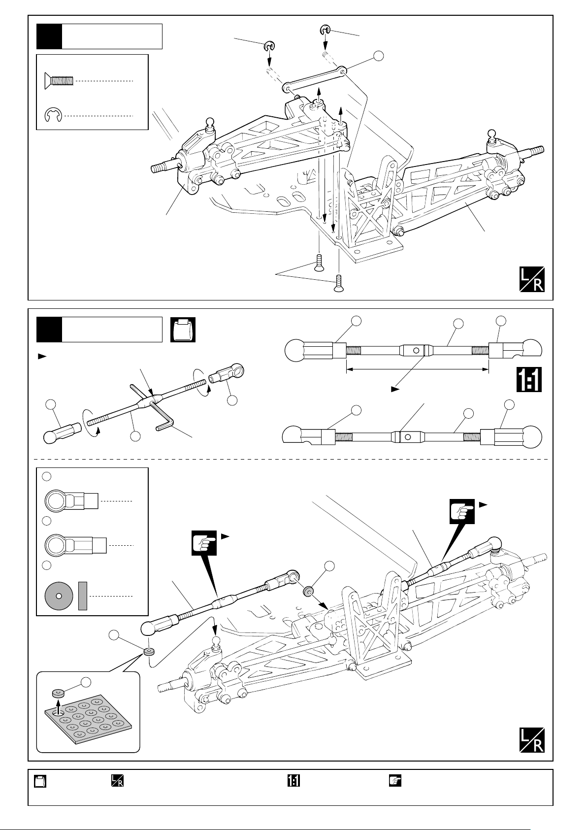
リヤサスペンション
Rear Suspension
10
3 x 10mm
F/H Cap Screw
E2.5
E-ring
サラキャップビス
Eリング
4
2
左側用
For Left
E2.5
3x10mm(F/H)
E2.5
227
右側用
For Right
リヤサスペンション
Rear Suspension
11
溝のある方が逆ネジ。
The side with the groove is a
reverse screw.
22
21
4.8mm
ボールエンド(中)
Ball End (Medium)
22
4.8mm
ボールエンド(長)
Ball End (Long)
231
ボールエンドシート
Ball End Sheet
224
< Left >
No.3, No.4
左側
21
六角レンチ
Hex Wrench
2
2
左側用
For Left
4
溝のある方。
The side with
the groove.
< Right >
右側
231
22
21
(中)
(Medium)
224
51mm
溝のある方。
The side with the groove.
224
右側用
For Right
21
(中)(長)
(Medium) (Long)
22
(長)
(Long)
溝のある方。
The side with
the groove.
使用する袋詰。
Part bags used.
10
231
231
左右同じように組立てる。
Assemble left and right sides the same way.
原寸図。
True-to-scale diagram.
注意して組立てる所。
Pay close attention here!
Page 11
リヤギヤボックス
Rear Gearbox
12
3x8mm
3 x 8mm
F/H Cap Screw
サラキャップビス
4
六角レンチ(2.5mm)
Hex Wrench (2.5mm)
3x25mm
3 x 8mm
Button Cap Screw
3 x 25mm
Button Cap Screw
ユニバーサルシャフト
を入れる。
Put universal shaft.
ボタンキャップビス
2
ボタンキャップビス
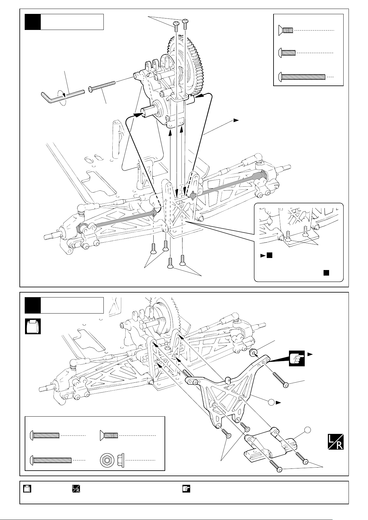
1
リヤダンパーステー
Rear Shock Stay
13
No.2, No.7
3 x 15mm
Button Cap Screw
ボタンキャップビス
3 x 10mm
F/H Cap Screw
2
サラキャップビス
3x8mm(F/H)
3x8mm
で仮止めしている
2
ビスをしめ込む。
3x8mm(F/H)
Tighten the screws which were
temporarily fixed the step .
3mm
3x22mm
225
向きに注意。
Note the direction.
2
取付穴。
Use this hole.
111
2
3 x 22mm
Button Cap Screw
使用する袋詰。
Part bags used.
ボタンキャップビス
2
左右同じように組立てる。
Assemble left and right sides the same way.
3mm
フランジ付ナット
Flanged Nut
2
3x10mm(F/H)
注意して組立てる所。
Pay close attention here!
3x15mm
11
Page 12
14
リヤバンパー
Rear Bumper
No.2, No.7
3x12mm(F/H)
3x8mm(F/H)
3 x 8mm
F/H Cap Screw
3 x 12mm
F/H Cap Screw
サラキャップビス
サラキャップビス
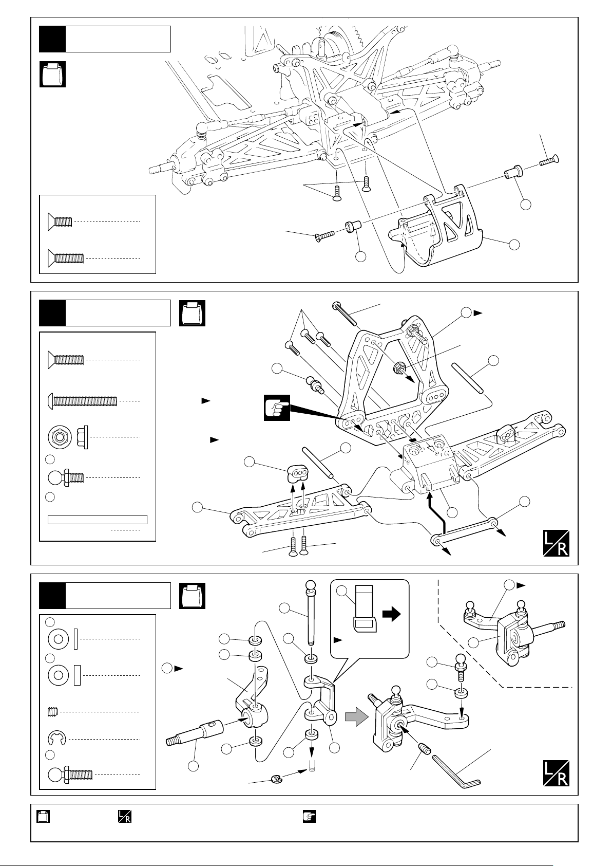
フロントサスペンション
Front Suspension
15
3 x 12mm
F/H Cap Screw
3 x 22mm
Button Cap Screw
3mm
Flanged Nut
59
4.8mm
Ball Stud (S)
228
3 x 34mm
Shaft
サラキャップビス
ボタンキャップビス
フランジ付ナット
ボールスタッド(S)
シャフト
112
2
3x12mm(F/H)
32
228
112
3x22mm
226
向きに注意。
Note the direction.
3mm
228
2
No.2, No.3,
3x12mm(F/H)
No.4
7
59
2
2
取付穴。
Use this hole.
向きに注意。
Note the direction.
2
2
1
2
3x12mm(F/H)
3x12mm(F/H)
16
227
フロントサスペンション
Front Suspension
16
3 x 7 x 1mm
30
Plastic Collar
3 x 7 x 2mm
31
Plastic Collar
3 x 3mm
Set Screw (
E2.5 E-ring
58
4.8mm
Ball Stud (L)
使用する袋詰。
Part bags used.
プラカラー
プラカラー
セットビス(緩み止め付き)
Apply cement to set screw
Eリング
ボールスタッド(L)
12
No.4
229
< Right >
右側
6
30
30
31
6
6
)
2
2
Rのマーク
“R” marked
30
31
56
2
左右同じように組立てる。
Assemble left and right sides the same way.
E2.5
8
向きに注意。
Note the direction.
前
Front
8
3x3mm
注意して組立てる所。
Pay close attention here!
58
31
5
Lのマーク
“L” marked
7
< Left >
左側
六角レンチ(1.5mm)
Hex Wrench (1.5mm)
Page 13

フロントサスペンション
Front Suspension
17
溝のある方が逆ネジ。
The side with the groove is a
reverse screw.
22
224
No.3, No.4
21
六角レンチ
Hex Wrench
< Left >
左側
< Right >
右側
22
21
(中)
(Medium)
224
52mm
溝のある方。
The side with the groove.
224
22
(長)
(Long)
21
(中)(長)
(Medium) (Long)
230
3 x 27mm
Shaft
21
4.8mm
Ball End (Medium)
22
4.8mm
Ball End (Long)
E2.5
E-ring
シャフト
ボールエンド(中)
ボールエンド(長)
Eリング
フロントサスペンション
Front Suspension
18
3 x 8mm
F/H Cap Screw
3 x 10mm
F/H Cap Screw
サラキャップビス
サラキャップビス
231
ボールエンドシート
Ball End Sheet
2
右側用
2
For Right
2
4
2
2
231
No.2
溝のある方。
The side with
溝のある方。
4
The side with
the groove.
E2.5
231
E2.5
the groove.
左側用
For Left
230
ステアリング
Steering
19
3 x 10mm
Set Screw
20
59
231
セットビス
4.8mm
ボールエンド(短)
Ball End (Short)
4.8mm
ボールスタッド(S)
Ball Stud (S)
ボールエンドシート
Ball End Sheet
3x10mm(F/H)
3x10mm(F/H)
3x8mm(F/H)
3x10mm
60
59
( Short)
20
2
2
5
231
短
2mm
23
25
231
61
59
59
4
No.3
62
向きに注意。
Note the direction.
33
3x8mm(F/H)
約24mm
approx. 24mm
231
59
24
使用する袋詰。
Part bags used.
左右同じように組立てる。
Assemble left and right sides the same way.
原寸図。 注意して組立てる所。
True-to-scale diagram. Pay close attention here!
13
Page 14

ステアリング
Steering
20
233
5x8x2.5mm
Ball Bearing
63
5 x 31mm
Aluminium Shaft
ベアリング
アルミシャフト
No.3
29
233
233
4
2
233
63
233
63
ボディマウント
Body Mounts
21
3x10mm(F/H)
3 x 8mm
サラキャップビス
F/H Cap Screw
3 x 10mm
サラキャップビス
F/H Cap Screw
3 x 18mm
ボタンキャップビス
Button Cap Screw
3mm
Washer
22
ワッシャー
フロントサスペンション
Front Suspension
溝のある方が逆ネジ。
The side with the groove is a
reverse screw.
2
2
2
2
22
224
No.2, No.4
No.3, No.4
六角レンチ
Hex Wrench
3x8mm(F/H)
21
14
22
(長)
(Long)
溝のある方。
The side with the groove.
溝のある方。
The side with the groove.
50.5mm
3mm
224
3x18mm
21
(中)
(Medium)
3mm
19
x2
溝のある方。
The side with
the groove.
21
4.8mm
ボールエンド(中)
Ball End (Medium)
22
4.8mm
ボールエンド(長)
Ball End (Long)
使用する袋詰。
Part bags used.
14
2
231
ボールエンドシート
Ball End Sheet
2
左右同じように組立てる。
Assemble left and right
sides the same way.
4
2セット組立てる(例)。
x2
Assemble as many times
as specified.
231
231
注意して組立てる所。
Pay close attention here!
ネジロック剤を塗る。
Apply threadlocker
(screw cement).
Page 15

ダンパー
Shock
23
80
3 x 6 x 1mm
Plastic Collar
81
3 x 7 x 1mm
Plastic Collar
92
Oリング(中)
Oリング
94
O-ring
86
5.8mm
Ball End (S)
プラカラー
プラカラー
8
ボールエンド(S) ボールエンド(L)
O-ring (M)
95
Cリング
C-ring
2
溝にはめる。
8
4
4
235
Fit into groove.
オイルを少し
付ける。
Put a little oil.
E2.5
E-ring
4
5.8mm
Ball End (L)
95
Eリング
8
2
No.5
235
4mm
95
81
94
80
94
80
92
76
< for Front >
フロント用
< for Rear >
リヤ用
フロント 2-C
79
Front 2-C
79
リヤ 2-B
Rear 2-B
E2.5
フロント用(短)
88
for Front (Short)
リヤ用(長)
89
for Rear (Long)
約27mm
approx. 27mm
約37mm
approx. 37mm
E2.5
x2
x2
オイルを
少し付ける。
Put a little oil.
ダンパー
Shock
24
ダンパー
Shock
25
フロント用(短)
77
for Front (Short)
リヤ用(長)
78
for Rear (Long)
フロント用(短)
for Front (Short)
リヤ用(長)
for Rear (Long)
フロント用(短)
77
for Front (Short)
リヤ用(長)
78
for Rear (Long)
No.5
プレッシャータイプ
Pressure Type
1
ピストンを下げ、
オイルを図の
位置まで入れる。
Pull down the
piston and slowly
fill in oil.
No.5
エアレーションタイプ
Non-Pressure Type
オイルを入れる。
1
Put the oil.
93
2通りのダンパーの組立てが出来ます。
75
4
85
96
0~1mm
もう一度図の位置
3
までオイルを足す。
Add oil one more
time up to the brim.
2
上下させ、気泡をとる。
Move the piston up and
down to get rid of air
bubbles.
伸ばしておく。
2
Keep expanded.
シャフトをゆっくり押し込む。
4
Insert the shaft slowly.
キャップを軽く止
3
まる所まで締め、
1/2回転ゆるめる。
Tighten the cap until it
slightly stops,
then loosen it for a
1/2nd lap.
You can assemble the shock in 2 ways.
, , の順に組立てる。
96 7585
Complete the shock assembly
in the order , and .
96 85 75
余分なオイルが出る。
Surplus oil comes out.
スムーズに動くか確認する。
5
Confirm that each piston
moves up and down
smoothly.
キャップを最後まで
5
締め込み、シャフト
を伸ばす。
Tighten the cap firmly,
and pull the shaft.
93
Oリング(大)
O-ring (Large)
使用する袋詰。
Part bags used.
85
75
4
2セット組立てる(例)。 別購入品。 をカットする。
x2
Assemble as many times
as specified.
Must be purchased
separately!
Cut off shaded portion.
余分なオイル
が出る。
Surplus oil comes out.
15
Page 16

26
ダンパー
Shock
No.5
240
5.8mm
Ball
27
ボール
238
フロント用(短)
for Front (Short)
239
リヤ用(長)
for Rear (Long)
ダンパー
Shock
No.5
98
82
8
スプリング調整用。
For adjusting the spring tension.
は5種類あるので………
98
1
車高の前後が、水平になるように
2
走行しながら………種類、個数を調節する。
exists in 5 widths. For making the F / R ground
98
clearance horizontal, choose the necessary width(s)
and amount of . When adjusting, run your car.
98
向きに注意。
83
Note the direction.
87
フロント用(短)
for Front (Short)
リヤ用(長)
for Rear (Long)
240
スプリングを縮めて を入れる。
Compress the spring and install .
84
84
84
< Rear >
リヤ
リヤ用(長)
For Rear (Long)
240
フロント用(短)
3x10mm
< Front >
フロント
87
プラナット
Plastic Nut
プロポ
Radio
28
3 x 10mm
Button Cap Screw
59
4.8mm
Ball Stud (S)
3mm
Washer
サーボに付属するビスと同じタイプを使用する。
Use screws which are same type included in your servo.
フタバ用
2.6 x 8mm
TP Screw
ボタンキャップビス
ボールスタッド(S)
ワッシャー
for FUTABA
TPビス ビス
1 1
3 x 10mm
Button Cap Screw
4
No.3
4
1
4
2.6 x 8mm
Screw
For Front (Short)
ボタンキャップビス
使用するサーボに合わせる。
Select for your servo.
FUTABA
SANWA
KO
JR
HITEC
サンワ用
3 x 8mm
Screw
4
HF S
for SANWA
ビス
ステアリングサーボ
Steering Servo
28
28
28
90
1
59
87
リヤ用(長)
For Rear (Long)
3x10mm
83
向きに注意。
Note the
direction.
27
26
3mm
3x10mm
F
下のサイズの場合は、 を使用します。
In case of the following sizes, use .
26
26
10mm以下の場合
Shorter than 10mm.
28mm以上の場合
Longer than 28mm.
使用する袋詰。
Part bags used.
16
左右同じように組立てる。
Assemble left and right sides the same way.
別購入品。
Must be purchased separately!
Page 17

29
プロポ
Radio
No.3
ステアリングサーボ
Steering Servo
3x10mm
( Short)
20
短
( Short)
20
短
3 x 8mm
F/H Cap Screw
3 x 10mm
Set Screw
20
サラキャップビス
セットビス
4.8mm
ボールエンド(短) ワッシャー
Ball End (Short)
1mm
231
ボールエンドシート
Ball End Sheet
2
1
3 x 10 x 1mm
Washer
2
2
2
エンジンの種類により説明が異なります。
Different caption depending on the engine you use.
GT15Sエンジンの場合
For the GT15 engine.
30-1
231
231
の説明を読んでください。
Follow the instruction step .
30-1
3x10x1mm
3x8mm(F/H)
NOVAROSSI, REX, TOPの場合
For the NOVAROSSI, REX, TOP.
SGシャフト仕様の場合
For the SG shaft type.
スタンダードシャフト仕様の場合
For the standard shaft type.
GTエンジン(No.31973)の場合
30-1
3 x 8mm
Button Cap Screw
51
5 x 10mm
Ball Bearing
241
3mm
Head Washer
For the GT15 engine.
ボタンキャップビス
5
ベアリング
2
ヘッドワッシャー
1
3mm
Washer
3 x 10mm
Cap Screw
129
ワッシャー
キャップビス
7 x 11 x 0.5mm
Shim
シム
4
4
2
30-2
30-3
30-4
の説明を読んでください。
Follow the instruction step .
の説明を読んでください。
Follow the instruction step .
の説明を読んでください。
Follow the instruction step .
30-2
30-3
30-4
3x10mm
取付穴。
Use this hole.
3x8mm
使用する袋詰。
Part bags used.
241
51
124
51
左右同じように組立てる。
Assemble left and right
sides the same way.
127
125
向きに注意。
Note the direction.
128
130
129
129
115
116
3mm
115
3mm
3x8mm
原寸図。別購入品。
True-to-scale diagram.Must be purchased separately!
仮止め。
Tentatively tighten.
17
Page 18

30-2
NOVAROSSI, REX, TOPの場合
For the NOVAROSSI, REX, TOP.
エンジン付属の
部品をはずす。
Remove the parts
attached the engine.
3x10mm
131
5 x 15mm
Pilot Screw
3 x 8mm
Button Cap Screw
パイロットボルト
ボタンキャップビス
7 x 11 x 0.5mm
129
Shim
1
3mm
5
Washer
241
3mm
Head Washer
51
5 x 10mm
Ball Bearing
シム
1
ワッシャー
4
ヘッドワッシャー
1
ベアリング
2
131
キット付属
Kit Includ.
3x8mm
242
51
241
SGシャフト仕様の場合
30-3
3 x 8mm
Button Cap Screw
51
5 x 10mm
Ball Bearing
241
3mm
Head Washer
5 x 7 x 3mm
245
Collar
For the SG shaft type.
ボタンキャップビス
ベアリング
ヘッドワッシャー
カラー
51
125
3 x 10mm
Cap Screw
5
243
7 x 10 x 4mm
Collar
2
244
パイロットナット
Pilot Nut
1
3mm
Washer
1
キャップビス
ワッシャー
128
127
向きに注意。
Note the direction.
129
4
カラー
5 x 8 x 0.2mm
1
Shim
5 x 8 x 0.5mm
Shim
1
4
129
130
116
3mm
115
7 x 11 x 0.5mm
Shim
シム
1
シム
1
シム
2
3mm
3x8mm
3x10mm
3 x 10mm
Cap Screw
キャップビス
取付穴。
Use this hole.
115
取付穴。
Use this hole.
4
OSの時・・・・・5x8x0.2mmシムを1枚
For OS, use one 5x8x0.2mm shim.
NOVAROSSIの時・・・・・5x8x0.5mmシムを1枚
For NOVAROSSI, use one 5x8x0.5mm shim.
5x8x0.5mm
5x8x0.2mm
3x8mm
左右同じように組立てる。
Assemble left and right sides the same way.
241
245
51
18
242
51
125
仮止め。
Tentatively tighten.
128
244
向きに注意。
Note the direction.
129
243
130
別購入品。
Must be purchased separately!
115
115
3mm
116
3mm
3x8mm
Page 19

スタンダードシャフト仕様の場合
30-4
3 x 8mm
Button Cap Screw
51
5 x 10mm
Ball Bearing
For the standard shaft type.
ボタンキャップビス
ベアリング
3 x 10mm
Cap Screw
5
129
2
キャップビス
7 x 11 x 0.5mm
Shim
シム
3x10mm
取付穴。
Use this hole.
4
3
13mm
241
3mm
ヘッドワッシャー
Head Washer
3x8mm
エンジン
Engine
31
2.6 x 25mm
Cap Screw
キャップビス
3mm
Washer
1
241
2
51
ワッシャー
51
No.6
242
127
4
115
115
3mm
3x8mm
125
向きに注意。
Note the direction.
128
130
129
116
3mm
121
160
エンジン
Engine
32
107
スティフナー(ドラムキャブの場合)
Stiffener (for a dram type carburetor)
268
スティフナー(スライドキャブの場合)
Stiffener (for a slide type carburetor)
スライドキャブレターの場合は を先にエンジン
とキャブレターの間に通しておく。
For a slide type carburetor, keep the in
between the carburetor and the engine.
268
268
268
3x8mm(F/H)
3x8mm(F/H)
2.6x25mm
紙1枚分のすき間をつくって仮止
めの3x8mmビスを固定する。
Firmly tighten the 3x8mm screws
with one sheet of paper inserted
between both gears.
3 x 8mm
F/H Cap Screw
サラキャップビス
4
使用する袋詰。
Part bags used.
左右同じように組立てる。
Assemble left and right
sides the same way.
仮止め。
Tentatively tighten.
別購入品。
Must be purchased
separately!
をカットする。
Cut off shaded portion.
19
Page 20

33
エンジン
Engine
No.2
107
3x10mm
107
3 x 12mm
Button Cap Screw
3 x 10mm
Button Cap Screw
ボタンキャップビス
1
ボタンキャップビス
1
プロポ
Radio
34
キャブレターがドラム式の場合
For the drum carburetor type.
3 x 8mm
Button Cap Screw
3 x 10mm
Button Cap Screw
3 x 15mm
Button Cap Screw
3mm
Washer
ボタンキャップビス
2
ボタンキャップビス
3
ボタンキャップビス
1
ワッシャー
4
No.7
スロットルサーボ
Throttle Control
247
Servo
スイッチ
Switch
3x15mm
3mm
3x10mm
161
3x10mm
3x12mm
3mm
161
3x8mm
キャブレターに当たる場合は削る。
Cut out the area if it touches carburettor.
下のサイズの場合は、 を使用します。
In case of the following sizes, use .
3x8mm
161
161
10mm以下の場合
Shorter than 10mm.
28mm以上の場合
Longer than 28mm.
108
キャブレターがスライド式の場合
For the slide carburetor type.
下のサイズの場合は、
161
を使用します。
In case of the following
sizes, use .
161
247
10mm以下
の場合
Shorter than
10mm.
28mm以上
の場合
Longer than
28mm.
スイッチ
Switch
のスリットに通す。
109
Pass it through the slit of .
3x10mm
3x15mm
3x10mm
3mm
161
109
3mm
161
3x8mm
109
のスリットに通す。
109
Pass it through the slit of .
スロットルサーボ
Throttle Control Servo
3x8mm
108
109
109
使用する袋詰。
Part bags used.
20
別購入品。
Must be purchased separately!
をカットする。
Cut off shaded portion.
Page 21

シャシー
Chassis
35
3 x 8mm
Button Cap Screw
ボタンキャップビス
3x10mm
3x8mm
2
3 x 10mm
Button Cap Screw
36
3 x 12mm
Button Cap Screw
ボタンキャップビス
プロポ
Radio
ボタンキャップビス
1
コネクターを出しておく。
First, pull out the cords.
3x12mm
3x12mm
2
バッテリー
Battery
プロポ
Radio
37
248
151
バッテリーコード
Battery Cord
グラステープ
等で巻く。
Fix with Glass
Tape, etc.
別購入品。
Must be purchased separately!
回転物、エンジン、マニホールド
などに当たらない様にする。
Keep this away from anyrotating parts.
21
Page 22

38
48
スナップピン
Snap Pin
プロポ
Radio
No.7
250
48
2
48
アンテナパイプ
Antenna Pipe
249
アンテナパイプ
Antenna Pipe
110
受信機
Receiver
プロポの説明書を参考に、
コネクターを接続する。
Connect as per radio
instruction manual.
マフラー
Muffler
39
3 x 8mm
Button Cap Screw
90°
40
3 x 10mm
Button Cap Screw
3mm
Washer
ボタンキャップビス
前
Front
ニードルの向きを変える。
Change the direction of needle.
プロポ
Radio
ボタンキャップビス
ワッシャー
3x8mm
251
4
3x8mm
3x10mm
146
シリコンチューブ(170mm)
Silicone Tube (170mm)
2
3mm
253
3x10mm
3mm
252
253
2
253
Oリング
O-ring
使用する袋詰。
Part bags used.
22
4
別購入品。
Must be purchased separately!
254
253
253
9080706050403020100
120 130 140 150 160 170mm110100
Page 23

マフラー
Muffler
41
3 x 8mm
F/H Cap Screw
サラキャップビス
No.6
120 122
122
2
120
4 x 4mm
Set Screw
セットビス
4x4mm
2
4x4mm
255
256
3x8mm
使用するエンジンによってリンケージ方法が異なります。
Depending on the engine you use, the linkage method is different.
GT15エンジンの場合
In case of GT15 engine.
OSエンジンのドラム式キャブレターの場合
In case of OS engine with a drum carburetor.
42-1
42-2
の説明を読んでください。
Follow the instruction step .
の説明を読んでください。 スライド式キャブレターのエンジンの場合
Follow the instruction step .
42-1
42-2
NOVAROSSIのドラム式キャブレターの場合
In case of NOVAROSSI engine with a drum carburetor.
In case of the slide carburetor engine.
163
270
マフラーに合わせて曲げる。
Bend and adjust to the muffler.
シリコンチューブ(160mm)
146
Silicone Tube (160mm)
ブリーザーパイプ
269
Pipe for spilling fuel.
42-3
42-4
の説明を読んでください。
Follow the instruction step .
の説明を読んでください。
Follow the instruction step .
42-3
42-4
42-1
GT15エンジンの場合
In case of GT15 engine.
3x3mm
154
257
3 x 3mm
セットビス
Set Screw
2mm
ワッシャー
Washer
154
ストッパー
Stopper
153
スプリング
Spring
4
1
3
2 x 8mm
Cap Screw
1
3x3mm
2x8mm
2mm
257
90mm
キャップビス
155
154
153
少し曲げる。
Bend.
154
3x3mm
約45°
approx. 45û
164
約10mm
2mm
約16.5mm
approx. 16.5mm
曲げる。
Bend.
約12mm
approx. 12mm
approx. 10mm
3x3mm
260
259
258
1
取付穴。
Use this hole.
使用する袋詰。
Part bags used.
別購入品。
Must be purchased
separately!
余分をカットする。 2mmの穴をあける(例)。
Cut off excess. Drill holes with the
可動するように組立てる。
Ensure smooth, non-binding
movement when assembling.
をカットする。
Cut off shaded portion.
2mm
specified diameter.
注意して組立てる所。
Pay close attention here!
23
Page 24

42-2
OSエンジンのドラム式
キャブレターの場合
In case of OS engine
with a drum carburetor.
2x8mm
3x3mm
153
155
154
154
3x3mm
154
257
3 x 3mm
セットビス
Set Screw
2mm
ワッシャー
Washer
154
ストッパー
Stopper
153
スプリング
Spring
4
1
3
2 x 8mm
Cap Screw
1
42-3
NOVAROSSIのドラム式
キャブレターの場合
In case of NOVAROSSI engine
with a drum carburetor.
3x3mm
2mm
257
90mm
キャップビス
1
3x3mm
2x8mm
153
154
164
155
2mm
約12mm
approx. 12mm
154
3x3mm
約10mm
approx. 10mm
約16.5mm
approx. 16.5mm
3x3mm
曲げる。
Bend.
260
259
258
取付穴。
Use this hole.
少し曲げる。
Bend.
約45°
approx. 45°
3x3mm
164
154
2mm
257
3 x 3mm
セットビス
Set Screw
2mm
ワッシャー
Washer
154
ストッパー
Stopper
153
スプリング
Spring
別購入品。 2mmの穴をあける(例)。 をカットする。可動するように組立てる。
Must be purchased
separately!
4
1
3
2 x 8mm
Cap Screw
1
movement when assembling.
257
90mm
キャップビス
1
2mm
約16.5mm
approx. 16.5mm
曲げる。
Bend.
約12mm
approx. 12mm
Cut off shaded portion.Ensure smooth, non-binding
約10mm
approx. 10mm
260
259
258
2mm
3x3mm
取付穴。
Use this hole.
Drill holes with the specified
diameter.
注意して組立てる所。
Pay close attention here!
24
Page 25

42-4
3x3mm
スライド式キャブレターのエンジンの場合
In case of the slide carburetor engine.
154
261
154
262
263
曲げる。
Bend.
261
2x8mm
3x3mm
153
2x8mm
164
2mm
3x3mm
154
3x8mm
137
257
164
約12mm
approx. 12mm
曲げる。
Bend.
3 x 8mm
ボタンキャップビス
Button Cap Screw
2mm
ワッシャー
Washer
153
スプリング
Spring
1
3 x 3mm
2
Set Screw
2 x 8mm
Cap Screw
1
スロットルリンケージ調整
Throttle Linkage Adjustment
43
< >ドラム式
Brake Neutral Full Throttle
< >Drum type
1mm
110mm
154
ストッパー
Stopper
セットビス
キャップビス
257
2mm
3
3
2
2mm
約7.5mm
approx. 7.5mm
約13mm
approx. 13mm
No.6
1mm
259
260
スロットルハイブレーキ ニュートラル
ブレーキ調整用。
For adjusting
the brake.
< >スライド式
Brake Neutral Full Throttle
1mm
使用する袋詰。 別購入品。
Part bags used. Must be purchased
スプリングが縮む。
Spring shrink. Adjust servo-horn to become neutral.
< >Slide type
スプリングが縮む。
Spring shrink. Adjust servo-horn to become neutral.
separately!
ニュートラルになる様に
サーボホーンの位置を調整する。
1mm
ニュートラルになる様に
サーボホーンの位置を調整する。
Ensure smooth, non-binding
movement when assembling.
スロットルハイブレーキ ニュートラル
をカットする。 2mmの穴をあける(例)。可動するように組立てる。
Cut off shaded portion. Drill holes with the
2mm
specified diameter.
25
Page 26

エアーフィルター
Air Filter
44
タイヤ
Wheels
45
< Front >
フロント
No.6
x2
< Rear >
リヤ
263
264
x2
101
99
(フロント用)
(for front) (for rear)
ピッタリはめてからタイヤとホイールの
つなぎ目に瞬間接着剤を流し接着する。
After fitting wheels to tyres, apply instant glue as shown.
タイヤ
Wheels
46
4mm
フランジ付ナイロンナット
Flanged Nylon Nut
5343/16 x 3/8
Ball Bearing
インチベアリング
4
102
裏から見た図。 裏から見た図。
Illustration from reverse side. Illustration from reverse side.
No.4
< Rear >
リヤ
4mm
103
100
(リヤ用)
102
ピッタリはめてからタイヤとホイールの
つなぎ目に瞬間接着剤を流し接着する。
After fitting wheels to tyres, apply instant glue as shown.
48
264
48
フックピン
Hook Pin
使用する袋詰。
Part bags used.
26
1
リヤ用
For Rear
フロント用
For Front
4mm
53
瞬間接着剤で接着する。
Apply instant glue (CA glue, super glue).
< Front >
フロント
53
左右同じように組立てる。
Assemble left and right sides the same way.
2セット組立てる(例)。
x2
Assemble as many times as specified.
Page 27

ボディ
Body Shell
47
シャシーに合わせて
穴をあける。
Make holes so body
can be put onto body
mounts.
シャシーに合わせて
穴をあける。
Make holes so body can
be put onto body mounts.
6mm
6mm
165
15
マフラーの排気口に
合わせてカットする。
mm
Cut out a hole in the
body shell just above
the exhaust hole in
the muffler.
塗装
Painting
48
塗装前に、洗剤で油やよごれを洗う。 ウインドウ部分に、内側から
1 2 3
Before painting, use a neutral detergent
to remove any oil residues and dirt.
マスキングシートを貼る。
Mask the windows from the inside.
京商スプレーカラーでボディ内側を塗装する。
Paint the body shell from the inside using
KyoshoÕs spray colors.
マスキング
Mask
マスキング
Mask
をカットする。 6mmの穴をあける(例)。
Cut off shaded portion. Drill holes with the specified diameter.
6mm
27
Page 28

ボディ
Body Shell
49
3 x 6mm
Button Cap Screw
3mm
Nylon Nut
ボタンキャップビス
ナイロンナット
3x6mm
125
両面テープ
Double-sided Tape
2
2
3x6mm
ビスで固定する場合は、
ウイングとボディに3mm
の穴をあけて固定する。
For fixing the wing witj screws,
drill holes of 3mm. dia.
3mm
50
デカール
Decals
デカールは、好きな位置に貼って下さい。
Decals with can be placed wherever you like.
51
48
28
ボディ
Body Shell
フックピン
Hook Pin
48
4
48
Page 29

走行上の注意
Safety Precautions
走行時は、必ずボディを装着してください。
下記の場所での走行は、故障の原因になりますのでおやめください。
・シャシーにからむような草の生えているところ。
・泥地、砂地、砂利の多いところ。
定期的に、各部のビス類が緩んでないか確認してください。
取扱いの注意 OPERATING YOUR MODEL SAFELY
次のような時、場所では走らせない。思わぬ事故の原因になります。
CAUTION: Do NOT operate the model in the following places and situations:
(Non-observance may lead to accidents!)
注意
●周囲に人がいなくて、広い安全な場所で!
1.自動車道路では走らせない。
2.近くに小さな子供がいたり、人の多い場所では走らせない。
3.民家の近くや公園などでは走らせない。
4.室内やせまいところでは走らせない。
※人にケガをさせる原因になります。また、物をこわしたり、
他人の迷惑になります。
Operate the model in spacious areas with no people
around! Do NOT operate it:
1. on roads!
2. in places where children and many people gather!
3. in residential districts and parks!
4. indoors and in limited space!
*
Non-observance may account
for personal injury and
property damage!
Always run your car with the body shell mounted!
Do not run your car on ground:
• that is overgrown with grass.
• that is muddy, sandy or rocky.
Check all screws, nuts etc. on a regular basis for looseness.
●プロポ関係の電池残量は常にチェックする。
電池が減ってくると電波の送・受信が弱くコントロール
ができなくなり、暴走や衝突の原因なります。
Always check the dry batteries in the radio!
When the dry batteries get weaker, transmission and reception of
the radio decrease. You may lose control of your model when
operating it under such condition. This may lead to accidents!
●近くで無線操縦模型を楽しんでいる人がいる。
同じバンドでの同時走行はできません。電波が混信して
コントロールができなくなり、暴走や衝突の原因なります。
Keep in mind that people around you may also
operate a radio control model!
NEVER share the same frequency
with somebody else at the same
time! Signals will be mixed and
you will lose control of your model.
This may lead to accidents!
01
05
事故やケガ等の危険防止のため、次のことを必ずお守りください。
CAUTION: in order to avoid accidents and personal injury,
注意
be sure to observe the following:
●燃料の取扱いは、必ず屋外で。
燃料の蒸気、排気ガスは有害です。
Handle fuel ONLY
outdoors!
Vapors and exhausts are
very noxious to health!
●回転している部分に、指や物などを入れない。
高速回転しているのでケガの原因になります。
Do NOT put fingers or any objects inside
rotating and moving parts!
Rotating / moving at high
speed, you may be
seriously injured!
●走行直後は、エンジン、マフラー周辺は高温になって
いるので、すぐにはさわらない。
ヤケドの原因になります。
Right after use, do NOT
touch equipment on the
model such as the engine
and muffler, because they
generate high temperatures!
You may burn yourself seriously touching them!
●車の動きがおかしい??とき。
すぐに走行を中止しておかしい原因を調べる、原因不明のまま
走行させると、思わぬ故障や事故の原因になります。
When the model is behaving strangely . . .!
Immediately stop the model and check the reason. As long as the
problem is not cleared, do NOT operate it! This may lead to further
trouble and unforeseen accidents!
●燃料は、模型用グロー燃料を必ず使用する。
ガソリンや灯油の使用は、火災等の事故の原因になります。
ONLY use glow fuel for radio control models!
Because the use of gasoline and kerosene in R/C models ac-counts for fires, do NOT use them!
●燃料は、引火性があります。
1.火気のあるところや室内では絶対に使用しない。
2.保管は、キャップをしっかりしめ、幼児の手の届かない冷暗
所に置くこと。
3.使用後の空缶は、火中には投げ入れない。爆発の原因になり
ます。
Fuel is highly inflammable and
high-explosive!
1. NEVER use fuel indoors or in places
with open fires and sources of heat!
2. Store fuel ONLY in cool, dry and dark
places out of children's reach! Tightly shut the cap!
3. Do NOT dispose of empty fuel cans into a fire! There is
danger of explosion!
●燃料は、飲んだり、目に入れたりしない。
万一、事故が起きた場合は、吐かせる、洗眼する等をした後、
すぐに医師の診察を受けてください。
NEITHER swallow fuel NOR let it into your eyes!
Immediate measures
should be taken:
if fuel is swallowed, in-duce vomit-ing. If fuel
gets into eyes, rinse
them and consult an
orphamologist!
29
Page 30

EXPLODED VIEW
< >
一部パーツ販売していないパーツがあります。
Parts indentified only by key numbers are not sold individually !
W0201
240
W5106
87
W5181-06
95
94
94
W5181-01
75
W5106
85
W5181-05
93
(2-C)
79
W5182-01
77
83
81
80
80
W5181-03
87
W5181-03
W5106
W5106
226
59
UM129
UMW105
A
W5181-04
92
98
W5106
82
W5182-55
238
84
W5129
W5106
W5181-02
76
W5182-02
88
UM129
59
162
UM145
92922
29
159
23
159
63
20
20
162
UM130B
C
UM112
UM112
UM145
59
92921
UM129
G
60
61
F
B
W0201
48
16
33
240
92638
UM108
UM115
LA43
233
162
UM145
162
15
UM145
G
UM111
19
UM112
21
22
162
K
UMW109B
14
UMW121
229
D
A
UM113
30
UM1047
UM107
F
UM112
UM145
21
224
J
UM112
224
FM370B
FM370B
22
UM112
H
C
UM113
UMW101
228
227
UM131
E
31
D
B
UM1011
UM1012
102
30
UM143
UM113
BRG015
53
H
UM143
101
UMW103
230
31
56
UM128
58
UM113
UM1035
UM126
159
I
48
62
159
63
109
92922
92638
92922
24
92921
92922
UM130B
UM204
UM145
162
59
25
UM129
92922
L
162
UM145
59
E
20
UM129
92922
28
Z
UM112
162
110
20
I
99
UM1036
1705
UM204
253
UM112
162
UM141
BRG015
53
UM1048
UM145
162
ORG03BK
Z
252
UM145
UM223BL
145
UM145
162
UM203B
139
ORG03BK
253
92922
26
UM217B
J
Y
UM222
154
UM218B
263
UM222
UM228
156 258 259 260
137
265
UM230
48
92638
48
92638
208
UM205B
83
W5106
W5181-05
W5183-01
78
W5181-03
81
80
80
UM218B
103
112
T
W5106
UM144
W5181-02
76
W
98
82
102
32
W5129
W5106
239
240
W5106
86
UM144
UM114
UM205B
112
FM314
248
96969
151
W5183-75
W5106
84
W0201
100
UM142
W5106
142
UM219
UMW119
13
UM105
162
UM145
87
213 212
UMW120
214
BRG014
52
UM216
UMW211
207
UM218B
141
UM121
41 39
71
6591
160
UM137
35
UM117
BRG003
50
121
BRG100
54
55
54
51
UM208
205
U
BRG001
143
Y
154
UM222
UM222
164
43
LA118
211
UMW118
42
210
UM122
UMW203
134
92696
135
P
92985
92696
134
138
152 153 154 155
W6011-5
X
BRG001
51
UM224
119
71
124
51
UM209
BRG001
UM212
128
269
120
125126
UMW203
209
UM210
127
UM211
UM213
130
264
133
129
92984
RM11
265
UM213
122
RM11
92601BK
BRG001
51
70
UM137
108
UM222
UM203B
241
W0148
M
UM224
146
146
ORG03BK
253
ORG03BK
253
UM203B
251
92050
254
92971
117
118
115
UM207B
116
215
R
S
T
27
L
92922
92511
N
M
UM217B
139
256255
UMW205
203
UMW205
204
O
P
Q
K
UM217B
247
X
R
UMW204
37
UM220
BRG001
51
BRG001
51
N
UMW308
12
UMW106
225
UM129
59
UM119
34
UM125
49
268107
UM112
21
224
UMW308
UM105
36
UM116
UMW205
FM370B
UM105
174
S
UM118
206
40
52
U
UM145
162
UMW308
74
BRG001
51
10
79
(2-B)
UMW123
UM119
37
50
UM121
BRG014
O
171
73
216
SP107V9
SP107V
BRG001
51
UM1024
87
111
240
W5106
W5181-03
BRG003
UMW308
UM205B
75
W0201
W5181-06
W5181-04
92
UM124
45
Q
58
10
W5181-01
85
95
94
94
W5183-02
89
UM112
22
UM145
162
UM128
SP107V
V
216
217
93
140
W
W5183-02
66
UMW201BL
201
267
UM226
UM1023
UMW104
V
222
GP ULTIMA ST Type-R EVOLUTION© 2003 KYOSHO CORPORATION / 禁無断転載複製
30
31
Page 31

品番
No.
UM101
UM102
UM103
UM104
UM105P
UM107
UM108
UM111
UM112
UM113
UM114
UM115
UM116
UM117
UM118
UM119
UM121
UM122
UM125
UM126
UM128
UM129
UM130B
UM131
UM137
UM139
UM140
UM141
UM142
UM143
UM144
UM145
UM203B
UM204
UM205B
UM206
UM207B
UM208
UM209
UM210
UM211
32
パーツ名
Part Names
フロントサスアーム
Front Suspension Arm
リヤサスアーム
Rear Suspension Arm
ナックルアーム
Knuckle Arm
フロントハブ
Front Hub
リヤサスホルダー
Rear Suspension Holder
フロントシャシー
Front Chassis
フロントバルクヘッド
Front Bulk Head
フロントボディマウント
Front Body Mount
4.8mmボールエンド
4.8mm Ball End Caps
3mmカラー
3mm Collars
リヤバンパー
Rear Bumper
フロントバンパー
Front Bumper
ボールデフシャフト(L)
Outdrive Diff half (L)
ボールデフシャフト(R)
Outdrive Diff half (R)
ボールデフギヤ
Ball Differential Gear
デフリング
Differential Ring
デフアジャストスクリュー
Differential Adjusting Screw
トルクコントロールハブインナー
Torque Control Hub Inner
アイドラギヤシャフト
Iddler Gear Shaft
フロントホイールアクスル
Front Wheel Axle
4.8mmボールスタッド(L)
4.8mm Ball Stud (L)
4.8mmボールスタッド(S)
4.8mm Ball Stud (S)
サーボセイバーシャフト
Servo Saver Shaft
フロントヒンジピンブレース
Front Hinge Pin Brace
ドライブピン&カラー
Drive Pin & Collar
ホイールピン
Wheel Pin
デカール
Decal
フロントホイール
Front Wheel
リヤホイール
Rear Wheel
フロントタイヤ
Front Tire
リヤタイヤ
Rear Tire
ボールエンドシート
Ball End Sheet
メカプレート
Radio Plate
レシーバーボックス
Radio Box
RXバッテリーホルダー
RX Battery Holder
メインシャシー
Main Chassis
エンジンマウント
Engine Mount
マニホールド
Exhaust Manifold
クラッチベル(17T)
Clutch Bell (17T)
クラッチシュー
Clutch Shoe
パイロットシャフト
Pilot Shaft
スペアパーツ SPARE PARTS
内容(キーNo.と入数)
Quantity
1 2 x 1
3 4 x 1
5 6 x 1
7 8 x 1
12 13
15
x 1
16
x 1
19
x 1
20 21 22
30 31
32
x 1
33
x 1
34
x 1
35
x 1
36
x 1
37
x 2
39 40 41
42
x 1
49
x 1
56
x 1
58
x 4
59
x 4
232
x 2
227
x 1
70 71
73 74
デカール
decals
99
x 2
100
x 2
101 102
102 103
231
x 16
108 251 252
109 110
111
x 1
201
x 1
115 116
121
x 1
124
x 1
125
x 1
127
x 1
223
x 1 x 2
x 6
x 6
x 1
x 1
x 2
x1
x 2
x 2
x 1
x 1
112
x 2
x 1
★定価
350
350
300
400
300
350
350
200
300
250
300
250
500
500
250
500
350
900
200
250
400
400
350
200
300
300
700
600
600
1800
1800
300
400
400
400
2800
400
2400
600
1400
300
★発送
手数料
200
(一律)
品番
No.
UM212
UM213
UM214
UM216
UM217BL
UM218B
UM219
UM220
UM222
UM223BL
UM224
UM226
UM228
UM229
UM230
UM231
UM232
UMW101
UMW103
UMW104
UMW105
UMW106
UMW109B
UMW118
UMW119
UMW120
UMW121
UMW122
UMW123
UMW201
BL
UMW203
UMW204
UMW205
UMW211
UMW308
FM314
FM370B
LA118
RM11
SP107V
パーツ名
Part Names
フライホイール
Flywheel
テーパーコレット
Tapered Collet
パイロットボルト(ノバロッシ)
Pilot Screw (Nova Rossi)
ブレーキレバー
Brake Lever
メカポスト
Radio Plate Post
ギヤボックス
Gear Box
スパーギヤ67T / 0.8M
Spur Gear 67T / 0.8M
アイドルギヤ
Iddler Gear
リンケージセット
Throttle Linkage Set
アッパープレートポスト
Upper Plate Post
燃料チューブ
Fuel Tube
リアヒンジピンブレース
Rear Hinge Pin Brace
ブレーキカム
Brake Cam
パイロットナット(SGシャフト用)
Pilot Nut (For SG Shaft)
リヤボディマウント
Rear Body Mount
キャップビスセット
Cap Screw Set
ボディ(GPアルティマST-EVO)
Body (GP Ultima ST-EVO)
ハードサスシャフト(フロントインナー)
Inner Front Hard Hinge Pin
ハードサスシャフト 24mm
Hard Hinge Pin 24mm
ハードサスシャフト 26mm
Hard Hinge Pin 26mm
カーボンコンポジットダンパーステー(F)
Carbon Composit Shock Stay (F)
カーボンコンポジットダンパーステー(R)
Carbon Composit Shock Stay (R)
カーボンコンポジットフロントアッパープレート
Carbon Composite Front Upper Plate
スペシャルスリッパーパッド
Special Slipper Pad
M4スラストブッシュ
M4 Thrust Bushing
M4テンショナースプリング
M4 Tensionner Spring
ハードキングピン
Hard King Pin
アクスルワッシャーセット
Axle Washer Set
タングステンカーバイト3/32ボール
Tungsten Carbide 3/32 Ball
ハードメインシャシー
Hard Main Chassis
ハードディスクホルダー
Hard Disk Holder
カーボンコンポジットリヤバルクヘッド
Carbon Composite Rear Bulkhead
カーボンコンポジットセンターバルクヘッド
Carbon Composit Center Bulkhead
M4メインギヤシャフト(GP)
M4 Top Gear Shaft (GP)
ユニバーサルスイングシャフト(ST)
Universal Swingshaft (ST)
小物パーツセット
Small Parts Set
アジャスタブルロッド(L=66)
Adjustable Rod (L=66)
ハイパーディスクプレート
Hyper Disc Plate
エアーフィルター(AB15)
Air Filter (AB15)
リヤハブ
Rear Hub
★FOR JAPANESE MARKET ONLY.
内容(キーNo.と入数)
Quantity
128
x 1
129 130
x 1
131
x 1
137
x 1
139 247
x 2 x 1
140 260141
142
143
153 155 156 157 158
161 164
3x3mmセットビス
3x3mm Set Screw
145
146
267
208
243 244 245 129
264
ビスセット一式
Screw Set
ボディ
body
228
230
222
226
225
14
211
212 213
214
229
73 74
206
201
209 210
205
207
73 74
248
224
43
262 263
9 x 2
10
x 1
x 1
x 1
x 2
154
x 2
x 1
x 1
3x3mmセットビス
x 1
3x3mm Set Screw
x 1 x ?
x 1
デカール
x 1 x 1
decal
x 2
Eリング(E2.5)
x 2
E-ring (E2.5)
Eリング(E2.5)
x 2
E-ring (E2.5)
x 1
x 1
x 1
x 1
x 1
M4フランジナット
x 1
M4 Flanged Nut
x 2
218217
x 2
x 12
x 1
x 1
x 1
203107 204 268
x 1
x 1
x 2
x 1
x 4
x 1
215 216 217 218
x ?
3x6x2mmカラー
3x6x2mm Collars
x 3
x 1
216
x 3
x 1
x 5
x 5
x 1
x 4
x 2
x 4
★定価
700
250
100
300
350
300
250
250
600
400
200
200
400
400
300
3200
2800
500
500
500
900
900
900
800
300
350
1200
400
1800
3200
900
1200
1200
700
3500
400
650
1200
250
300
★発送
手数料
200
(一律)
Page 32

品番
No.
W0201
W5017
W5106
W5129
W5181
-01
W5181
-02
W5181
-03
W5181
-04
W5181
-05
W5181
-06
W5182
W5182
-01
W5182
-55
W5183
W5183
-01
W5183
-02
W5183
-75
W6004
W6005
パーツ名
Part Names
5.8mmスチールボール
5.8mm Steel Ball
プレッシャートップ
Shock Diaphragm
プラパーツ
Shock Plastic Parts
セッティングスペーサー
Setting Spacer
ダンパーキャップ
Shock End Cap
シールカートリッジ
Lower Shock Cartridge
ダンパーピストン
Shock Pistons
ダンパーシール(S)
Shock Seal O-ring (S)
ダンパーシール(M)
Shock Seal O-ring (M)
リビルドセット
Shock Rebuild Set
ツインキャッププロショック(M)
Twin Cap Pro Shock (M)
テフロンダンパーケース(M)
Teflon Shock Case (M)
スプリング(M)#55
Spring (M) #55
ツインキャッププロショック(L)
Twin Cap Pro Shock (L)
テフロンダンパーケース(L)
Teflon Shock Case (L)
ダンパーシャフト(L)
Shock Shaft (L)
スプリング(M)#75
Spring (M) #75
チタンコーティングダンパーシャフト(46)
Titanium Coating Dumper Shaft (46)
チタンコーティングダンパーシャフト(54)
Titanium Coating Dumper Shaft (54)
スペアパーツ SPARE PARTS
内容(キーNo.と入数)
Quantity
97
x 10
96
x 10
82 83 85 8784
98
75
x 1
76
x 1
x 8
79 80 81
92
x 4
93
x 4
94
x 4
75 76 77 82 83 84 85
86 87 88 92 93 96
95
x 380x 8
81 94 79
x 4 x ?
ダンパースプリング
Shock Spring
Eリング(E2.5)
E-ring (E2.5)
77
x 1
238
x 2
75 76 78 82 83 84 85
86 87 89 92 93 96
95
x 380x 8
81 94 79
x 4 x ?
ダンパースプリング
Shock Spring
Eリング(E2.5)
E-ring (E2.5)
78
x 1
221
x 2
239
x 2
236
x 2
237
x 2
x 2
x 8
95
x 3
x 2
x 2
x 5
x 2
x 2
x 5
★定価
700
200
450
200
250
300
200
250
250
350
3500
900
550
3500
900
600
550
1200
1200
★発送
手数料
200
(一律)
品番
No.
BRG001
BRG002
BRG003
BRG014
BRG015
BRG100
1701
KP/KY
1708
6591
92050
92511
92601
BK
92638
92696
92921
92922
92971
92984
92985
96969
パーツ名
Part Names
5x10x4mmベアリング
5x10x4mm Ball Bearing
5x8x2.5mmベアリング
5x8x2.5mm Ball Bearing
4x8x3mmベアリング
4x8x3mm Ball Bearing
10x15x4mmベアリング
10x15x4mm Ball Bearing
3/16x3/8インチベアリング
3/16x3/8 Inch Bearing
デフスラストベアリング
Differential Thrust Bearing
ストラップ(M)
Strap (M)
アンテナ
Antenna
ガスケット
Gasket
燃料タンク(75cc皿付)
Fuel Tank (75cc Plate)
マフラーステー
Muffler Stay
マフラージョイントパイプ
Muffler Coupler
スナップピン
Snap Pin
ディスクブレーキパッド
Disc Brake Calibers
セイバーチューブ&スプリング
Servo Saver Tube & Spring
サーボセイバー
Servo Saver
サイレントストリークチューンドマフラー
Silent Streak Tuned Muffler
ディスクローター
Disc Brake Rotor
ハードブレーキライニング
Hard Brake Pads
BEC延長コード
BEC Extension Cord
★FOR JAPANESE MARKET ONLY.
内容(キーNo.と入数)
Quantity
51
x 4
233
x 4
50
x 2
52
x 2
53
x 2
54
x 2
55
x 8
163
x 18
162
x 6
249 250
x 4
160
x 5
254
x 1
255 256
x 1
3x8mmサラビス
3x8mm Flat Head Screw
4x4mmセットビス
4x4mm Set Screw
122
x 2
48
x 10
134
x 2
60 61 62
23 24 25 29
26 27
3x10mmバインドビス
3x10mm Bind Screw
2.6x10mmTPバインドビス
2.6x10mm TP Bind Screw
120
133
135
151
x 1
x 1
x 4
x 1
x 2
x 1
28
x 1
x 3
159
x 2
x 1
x 4
x 2
x 1
(各)
★定価
1000
1000
800
1200
1000
400
250
500
200
1500
600
800
200
300
500
300
1200
500
400
300
★発送
手数料
200
(一律)
キットの部品の一部にはスペアパーツとして販売していない物があります。京商ではオプションパーツを販売していますのでお買い求めください。
Some of the parts included are not available as spare parts. Purchase optional parts instead.
33
Page 33

品番
No.
UMW202
UMW207
UMW208
UMW209
UMW210
UMW216
W5182
-60
W5182
-65
W5182
-09
W5182
-75
W5183
-03 (#50)
W5183
-60 (#60)
W5183
-65 (#65)
W5183
-04 (#70)
W5183
-80 (#80)
パーツ名
Part Names
スチールフライホイール
Steel Flywheel Set
4ピースクラッチベル
4-piece Clutch Bell
4ピースクラッチシュー
4-piece Clutch Shoe
マフラー
Muffler
マニホールド
Manifold
ワンピースクラッチベル 16T
One-piece Clutch Bell 16T
スプリング(M)#60
Spring (M) #60
スプリング(M)#65
Spring (M) #65
スプリング(M)#70
Spring (M) #70
スプリング(M)#75
Spring (M) #75
スプリング(L)#50
Spring (L) #50
スプリング(L)#60
Spring (L) #60
スプリング(L)#65
Spring (L) #65
スプリング(L)#70
Spring (L) #70
スプリング(L)#80
Spring (L) #80
オプションパーツ OPTIONAL PARTS
内容(キーNo.と入数)
Quantity
★定価
800
900
1600
3800
2000
2400
550
550
300
550
300
550
550
300
550
★発送
手数料
200
(一律)
品番
No.
1790
39308
39771
71312
71641
80951B
96421
96422
パーツ名
Part Names
カラーシリコンチューブ
Color Silicone Tube
燃料フィルター
Fuel Filter
マルチスターターボックス
Multi Starter Box
6V-600mAhニカドバッテリー
6V-600mAh Ni-Cd Battery
6V-1000mAhニカドバッテリー
6V-1000mAh Ni-Cd Battery
フライホイールレンチ
Flywheel Wrench
クイックフュールポンプ(250cc)
Quick Fill Fuel Bottle (250cc)
クイックフュールポンプ(500cc)
Quick Fill Fuel Bottle (500cc)
★FOR JAPANESE MARKET ONLY.
内容(キーNo.と入数)
Quantity
受信機用電源
for receiver
受信機用電源
for receiver
★定価
400
1000
9800
3800
4000
1200
900
1200
★発送
手数料
200
(一律)
34
Page 34

SCREW • NUT etc.ビス・ナット類
品番
No.
1101
1102
1103
1104
1105
1106
1110
1111
1112
1113
1114
1115
1118
1119
1120
1121
1122
1123
1124
1125
1126
1127
1128
1129
1130
1131
サイズ(mm)
Size (mm)
ナベビス
Round Head Screw
2x6・2x8・2x10・2x15 5 each 10 each
2.6x8・2.6x10・2.6x12・2.6x14
3x4・3x6・3x8・3x10・3 x12
3x14・3x16・3x18・3x20
4x6・4x8・4x10・4x12
3x22・3x24・3x26・3x28
バインドビス
Bind Screw
2.6x4・2.6x6・2.6x8・2.6x12
3x4・3x6・3x8・3x10・3x12
3x14・3x16・3x18・3x20
4x6・4x8・4x10・4x12
3x22・3x25・3x28・3x30
4x15・4x18・4x20・4x22
サラビス
Flat Head Screw
2.6x8・2.6x10・2.6x12・2.6x14
3x6・3x8・3x10・3x12
3x14・3x16・3x18・3x20
4x8・4x10・4x15・4x20
3x22・3x24・3x26・3x28
3x30・3x32・3x34・3x35
キャップビス
Cap Screw
2x8・2x10・2x12・2x14
2.6x8・2.6x10・2.6x12・2.6x14
3x8・3x10・3x12・3x14
3x15・3x16・3x18・3x20
3x25・3x30・3x35・3x40
4x10・4x15・4x20
4x25・4x28・4x30
4x35・4x40・4x45
入数(各)
QUANTITY
●200 ●200
5 each
5 each
5 each
5 each
5 each
●200
5 each
5 each
5 each
5 each
5 each
5 each
●200
5 each
5 each
5 each
5 each
5 each
5 each
●200
2 each
2 each
2 each
2 each
2 each
2 each
2 each
2 each
品番
No.
1132
1133
1134
1135
1136
1137
1140
1141
1142
1143
1147
1148
1149
1150
1153
1154
1157
1160
1161
1162
1163
1164
1165 3x20・3x25 3 each
サイズ(mm)
Size (mm)
ナベタッピングビス
Round Head Self-Tapping Screw
2x4・2x6・2x8・2x10 5 each
2.6x6・2.6x8・2.6x10・2.6x12
3x6・3x8・3x10・3x12・3x14
3x15・3x16・3x18・3x20
3x25・3x30・3x35
2.6x14・2.6x15・2.6x16・2.6x18
バインドタッピングビス
Bind Self-Tapping Screw
2.6x6・2.6x8・2.6x10・2.6x12
3x6・3x8・3x10・3x12・3x14
3x15・3x16・3x18・3x20
4x10・4x15・4x18
サラタッピングビス
Flat Head Self-Tapping Screw
2.6x6・2.6x8・2.6x10・2.6x12
3x6・3x8・3x10・3x12・3x14
3x15・3x16・3x18・3x20
4x15・4x20・4x25
フランジ付キャップビス
Flanged Cap Screw
3x6・3x8・3x10
4x8・4x10・4x12
サラ小丸ビス
Oval Head Screw
2x8・2x10
セットビス
Set Screw
3x6・3x12・3x14・3x16
3x3・3x4・3x5・3x10
4x4・4x5・4x8・4x12
5x4・5x5・5x6
5x30・5x40
入数(各)
QUANTITY
●200
5 each
5 each
5 each
5 each
5 each
●200
5 each
5 each
5 each
5 each
●200
5 each
5 each
5 each
5 each
●200
2 each
2 each
●200
10 each
●200
3 each
3 each
3 each
3 each
3 each
● FOR JAPANESE MARKET ONLY.
品番
No.
1171
2mm・2.6mm
1172
3mm・4mm
1174
3mm
1175
4mm
1177
2.6mm
1178
3mm
1179
4mm
1180
4mm
1185
2mm・2.6mm・3mm
1186
4mm・5mm
1380
E1.5
1381
E2.0
1382
E2.5
1383
E3.0
1384
E4.0
1385
E5.0
1386
E6.0
1387
E7.0
1390
E10.0
ここに明記された以外のビス、ナット等は
『ユーザー相談室』にお問い合わせください。
径
mm
ナット
Nut
フランジ付ナット
Flanged Nut
ナイロンナット
Nylon Nut
フランジ付ナイロンナット
Flanged Nylon Nut
ワッシャー
Washer
Eリング
E-Clips
入数(各)
QUANTITY
10 each
●200
10 pcs
10 pcs
●200
5 pcs
5 pcs
5 pcs
●200
5 pcs
●200
10 each
10 each
●150
10 pcs
10 pcs
10 pcs
10 pcs
10 pcs
10 pcs
10 pcs
6 pcs
6 pcs
35
Page 35

*発送手数料、消費税率は平成15年2月1日現在のものです。
"Kyosho Direct-Mail-Parts-Order-System" is available only for Japanese market.
京商スペアパーツ・オプションパーツの購入方法
部品を
こわしちゃった
●部品をこわしたり、なくしてしまった場合で
もスペアパーツ や オプションパーツ を 購 入
し、元どおりに直す事ができます。
●
パーツ は お店で 直 接 購入し て いただ く か、お
店に行けない場合は、インターネットか郵便を
利用して京商から通信販売で購入できます。
※電話での直接のご注文は取り扱っておりませ
んので予めご了承ください。
1.まずはお店でお求めください。
まずは、お近くのお店か、この商品をお買い求めいただいたお店にご来店ください。ご希望のパーツの在庫が
あれば即購入できます。その際に組立/取扱説明書をお持ちになると購入がスムーズになります。
お店で在庫切れの場合でも京商の『パーツ直送便』
これらの購入方法は日本国内に限らせていただきます
購入方法による手数料、お届け日数のめやす。
購入方法 発送手数料
お店で
お店に在庫がない場合は
パーツ直送便で
現金書留で
お店に
行けない場合
※お届け予定 日数は夏・冬期休業また は交通事情等運送上の理 由により。
遅れる場合がございますのでご了承ください。
※
でお店から京商へ申し込めます
郵便振込で
インターネットで
不要
200
200
お支払い方法により
異なります。
円
円
お届け予定日数
日
3〜4
日
6〜7
日
10〜12
日
3〜4
お店でご希望のパーツがたまたま品切れだった場合でも、京商の『パーツ直送便』※を利用すればその場で注文でき
ます。『パーツ直送便』は、お店に備え付けのパーツ直送便注文用紙にご希望のパーツの品番や数量等、必要事項
をご記入の上、お店に代金をお支払いいただければ結構です。3〜4日でお客様のご自宅か、お店にお届けします。
発送手数料が不要で早く着くお得なシステムです。
※一部取り扱っていないお店もございます。
お店でパーツ直送便
注文用紙に『品番』
と必要数を記入。
パーツ直送便の
注文用紙といっしょに
代金をお店の人に
支払う!
発送手数料は
不要
3〜4日でお客様の
ご自宅かお店に
お届けします。
お届けまで
日
3〜4
パーツ直送便取り扱い店は
このステッカーが目印
2.お店に行けない場合は
次の3つの方法で京商から通信販売で購入できます。
お店に行けない場合は、京商ホームページ(http://www.kyosho.co.jp/)内のパーツオンラインショップからお申し込みいただくか、郵便局からお申し込みいただくようになります。
1
インターネットで京商へ申し込む
京商ホームページ(http://www.kyosho.co.jp/)内のインデックス
から
パーツオンラインショップをクリックしてください。
パーツオンラインショップ(インターネット)でお申し込みの
場
合は、右側の3種類(KYOSHOカード、
各社クレジットカード、代引支払い)から
お選びいただけますのでご利用ください。
お届けまで
日
3〜4
KYOSHOカードで
お支払いの場合
発送代引手数料
不要
特典満載KYOSHOオフィシャルカード
お申し込みが、京商ホームページ
(http://www.kyosho.co.jp/)
でもOK!!
各社クレジットカードで
お支払いの場合
発送手数料
の
代引にてお支払いの場合
発送及び
代引手数料
200
1000
円
円
2
現金書留で京商へ申し込む
必要事項を記入した用紙と代金を現金書留
にて京商までご送金ください。代金は次の
とおりとなります。
発送手数料
円
200
お届けまで
日
6〜7
3
郵便振込で京商へ申し込む
郵便局で払込用紙に必要事項をご記入のう
え、代金を郵便振込にて京商までご送金く
ださい。代金は次のとおりとなります。
発送手数料
円
200
郵便振込のほうが
現金書留より郵便料金が
安いね。
お届けまで
10〜12
●代金は、スペアパーツの定価の他に発送手数料(一律200円)と消費税がかかります。
●代金の計算方法は、代金=(パーツの定価の合計+発送手数料200円)×消費税1.05(1円未満は四捨五入)
《払込用紙の記入例》
(1)
払 込 取 扱 票 払込票兼受領証
00
口座番号 (右詰めにご記入ください)
※ ※
0 0 2 1 0 4 4 7 2 7 1
加
各票の※印欄は
※
入
者
名
京商株式会社
※
品番 パーツ名 数量
通
払込人において記載してください
(3)
1901 ベアリング 2
信
発送手数料
(例)
消費税
(部品+発送手数料合計金額x5%)
欄
合計
払
込
(郵便番号 )
※
人
住
所
氏
名
裏面の注意事項をお読みください。(郵政省)
金
額
料
金
(2)
(電話番号 ‑ ‑ )
千 百 十 万 千 百 十 円
(1)口座番号:00210‑4‑47271
(1)
※
口
0 0 2 1 0 4
1 6 8 0
座
殊
特
番
(4)
※
号
加
切り取らないで郵便局にお出しください
記
※
入
載
者
事
名
項
を
金
千 百 十 万 千 百 十 円
訂
※
正
額
し
た
場
※
払
合
込
は
人
住
そ
所
の
氏
箇
所
名
に
訂
正
料
(消費税込み)
印
を
押
金
し
て
く
だ
さ
特殊取扱
い
右詰めにご記入ください
4 7 2 7 1
京商株式会社
1 6 8 0
(2)
受付局日附印
円
扱
取
1,400
200
80
1,680
受
付
局
日
附
印
加入者名:京商株式会社
(2)あなたの 氏名・電話番号・郵便
番号
・
住所 を必ず記入してく
だ さい。(電話番号は登録
を スムーズにするためのもの
です。 必ずご記入ください)
(3 )注 文する 、品番・パー ツ名・注
文数を必ず記入してください。
(4)お間違えのないよう合計金額
を記入のうえ、ご送金ください。
(1)
氏 名
電
郵便
話番号
住
パーツ
番号
品 番
数 量
所
名
(2)
243 0034
神奈川県厚木市船子153
京商株式会社
ユーザー相談室
電話046‑229‑4115
(1)メモ用紙に氏名・電話番号・郵便番号
住所(電話番号は登録・発送をスムー
・
ズにするためのものです。必ずご記入
ください)と注文するパーツ名・品番
注文数を必ず記入してください。
・
(2)お間違えのないよう代金といっしょ
に郵便局よりご送金ください。
《現金書留の宛先》
〒243‑0034神奈川県厚木市船子153
京商株式会社ユーザー相談室
電話046‑229‑4115
京商株式会社
〒243‑0034神奈川県厚木市船子153●お問い合わせはユーザー相談室まで 電話046‑229‑4115 受付時間:月〜金曜(祝祭日を除く)10:00〜18:00
日
・
発送
Page 36

The service mentioned below is available only for Japanese market.
組立や、操作上で不明な点のお問い合わせ方法
これらのサービスは日本国内に限らせて頂きます
組立てたり、操作してみて上手くいかない点などございましたら、ご購入いただいた
販売店または、京商ユーザー相談室へお問い合わせください。
京商ユーザー相談室へお問い合わせの際は、お電話いただくか、下記のお問い合わせ
用紙に必要事項をご記入のうえ、
京商へのお問い合わせ先→「京商ユーザー相談室」
京商にお問い合わせの際は、「京商ユーザー相談室」にご連絡ください。
お問い合わせの際は、お手元に商品や組立/取扱説明書をご用意のうえ、組立/取扱説明書のページ数,行程番号, 部品番
号(キーNo.)を用いるなど、なるべく具体的にお知らせください。
ファ ック ス
または郵便でお送りください。
電話でのお問い合わせ:
ファックス
でのお問い合わせ:
郵便でのお問い合わせ:
046‑229‑4115
046‑229‑1501
〒243‑0034神奈川県厚木市船子153京商株式会社ユーザー相談室
電話でのお問い合わせは、月曜〜金曜(祝祭日を除く)10:00〜18:00。
ファックスでは、24時間お問い合わせの受付をして居ります。回答は、翌営業日
以降となる場合があります。営業日:月曜〜金曜(祝祭日を除く)
キリトリ線
お問い合わせ用紙
お問い合わせ用紙は、フ ァ ッ ク ス または郵便でお送りください。回答方法は、京商で検討のうえ考慮させて頂きます。
郵送の場合は、お問い合わせ用紙のコピーを保管してください。
品番 商品名
ご購入店
ご使用
プロポ
ご氏名
ご自宅
住所
ご自宅の
連絡先
平日の昼間に
可能な連絡先
月曜〜金曜(祝祭日を除く)10:00〜18:00で電話連絡可能な時間帯: 頃
No.31973
店名
メーカー名 商品名
フリガナ
〒___−____
都道
府県
電話 ( )
電話 ( )
GPアルティマSTType‑REVOLUTION
都道府県
()電話
ご使用の
モーター
性別
生年月日
ファックス
ファックス
( )
( )
受付No.(京商記入欄)
ご購入
年月日
平成 年 月 日
男/女
大正/昭和/平成
R/C歴
約年
年月日
お問い合わせご記入欄:
組立/取扱説明書のページ数や部品番号(キーNo.)を用いるなど、なるべく具体的にご記入ください。
PRINTED IN JAPAN61920302-1
Page 37

THE FINEST RADIO CONTROL MODELS
京商ホームページ
http://www.kyosho.co.jp/
R
メーカー指定の純正部品を使用して
安全にR/Cを楽しみましょう。
36
京商株式会社
〒243-0034 神奈川県厚木市船子153
●ユ−ザ−相談室直通電話 046-229-4115
お問い合わせは:月曜〜金曜(祝祭日を除く) 10:00〜18:00
PRINTED IN JAPAN61920302-1
 Loading...