

Page 1
※ご使用前にこの説明書を良くお読みになり十分に理解してください。
Before commencing assembly, please read these instructions thoroughly.
R
THE FINEST RADIO CONTROL MODELS
INSTRUCTION MANUAL
GP TR-15 RALLY 4WD
三菱ランサーエボリューションVIIWRC
MITSUBISHI LANCER EVOLUTION
目 次 INDEX
このキットは、半完成キットです。
8ページ 〜10ページ までの組み立ては終っています。1 8
●キットの他にそろえる物 REQUIRED FOR OPERATION
●プロポの準備 RADIO PREPARATION
●組立て前の注意 BEFORE YOU BEGIN
●本体の組立て ASSEMBLY
●取扱いの注意 OPERATING YOUR MODEL SAFELY
●スペアパーツ・オプションパーツリスト SPARE PARTS & OPTIONAL PARTS
●分解図 EXPLODED VIEW
This kit is half assembled.
Please start assembling from page 8 ~10 .
1 8
組立/取扱説明書
GPTR‑15ラリー4WD
VII
WRC
2 〜 3
4 〜 5
6 〜 23
25 〜 27
28 〜 29
3
24
安全のための注意事項
この無線操縦模型は玩具ではありません!
●
この商品は高い性能を発揮するように設計されています。組立てに不慣れな方は、
模型を良く知っている人にアドバイスを受け確実に組立ててください。
●小さい部品があるので、組立て作業は幼児の手がとどかない所で必ずおこなって
ください。
●動かして楽しむ場所は、万一の事故を考えて安全を確認してから、責任をもって
お楽しみください。
●組立てた後も、説明書がいつでも見られるように大切に保管してください。
※製品改良のため、予告なく仕様を変更する場合があります。 *SPECIFICATIONS ARE SUBJECT TO CHANGE WITHOUT NOTICE.
© 2001 KYOSHO/禁無断転載複製
●First-time builders should seek the advice of experienced modellers before
commencing assembly and if they do not fully understand any part of the
construction.
●Assemble this kit only in places out of children’s reach!
●Take enough safety precautions prior to operating this model. You are responsible
for this model’s assembly and safe operation!
●Always keep this instruction manual ready at hand for quick reference, even after
completing the assembly.
SAFETY PRECAUTIONS
This radio control model is not a toy!
No. 31061
Page 2
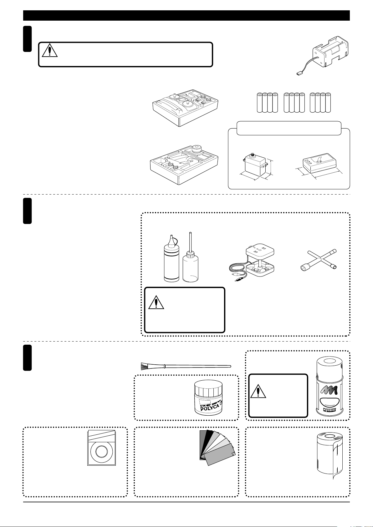
REQUIRED FOR OPERATION (1)キットの他にそろえる物(1)
2チャンネル2サーボ無線操縦機(プロポ)と電池ボックス
Minimum 2 channel radio with 2 servos, and battery box.
1
地上用(自動車用)のプロポ(2チャンネル2サーボ仕様)セットを
必ず使用してください。(地上用以外使用禁止)
CAUTION: Only use a surface radio with 2 channels and 2 servos!
注意
●送信機にはスティックタイプとハンドル
タイプがありますが、お好みのタイプを
用意してください。
■スティックタイプ
Stick-type
2ch radio.
●リバース付送信機を使用してください。
●プロポの取扱いは、プロポに付属の説明
書を参考にしてください。
●Because there are stick-type and wheel-
type transmitters, use which ever fits
your convenience best.
●Use a transmitter with reverse function.
●For more information on the radio, refer
■ハンドルタイプ
Wheel-type
2ch radio.
to its instruction manual.
燃料と始動用具
2
Required for engine starting:
●模型用エンジンは専用のグロー燃料が必
要です。ガソリンや灯油は使用できませ
んので注意してください。また、グロー
燃料は揮発性が高く引火しやすいので取
扱いには十分注意してください。
●エンジン始動にはその他に、プラグを赤
熱させるプラグヒーター(ブースターコ
ード+乾電池)、プラグを脱着するプラ
グレンチが必要です。
●Engines for R/C models require glow fuel.
Be careful not to purchase gasoline or
kerosene by mistake; both cannot be
used! Also, be very careful when han-dling glow fuel which is hi-ghly inflamma-ble and high-explosive!
●Besides glow fuel, engines also require
engine starting equipment. This comprises a glow plug heater (booster cord &
batteries) and a plug wrench for removing and installing the glow plug.
■グロー燃料、燃料ポンプ
Glow Fuel & Fuel Pump
警告
HANDY
FUEL
ガソリンや灯油は
使用禁止
WARNING: Gasoline
or kerosene cannot
be used.
■電池ボックス
Battery Box
●プロポセットに付いていると
きは必要ありません。
If already included with the
radio, no battery box needs
to be pur-chased separately.
■単3乾電池
AA-size Batteries
AAAA
AAAA AAAA
使用できるサーボ・受信機サイズ
Suitable servos & receiver
■サーボ
Servo
31〜36mm
38〜41mm
18〜20mm
■ブースターコード
Booster Cord
●エンジン始動に必要な用具(上記3点)を
セットにしました。
No.73301 スターターパック
29〜32mm
■受信機
Receiver
43〜48mm
■プラグレンチ
Plug Wrench
塗料と筆
3
Paint and Brush
●ボディの塗装には塗料が必要です。
京商ではモ デル 用塗 料、スプレーを
用意していますのでご利用ください。
●For painting the body, use Kyosho
paints for models!
No.1841
1842
1843
1859
1860
(1mm x 5m)
(1.5mm x 5m)
(2.5mm x 5m)
(0.4mm x 8m)
(0.7mm x 8m)
Micr
Lin
on
KYOSHO
e Tap
e
ミクロンラインテープ
MICRON LINE TAPE
マスキング、細部デザイン用伸縮自在テープです。
Super-flexible tape for masking and detail designing
jobs.
2
■筆
PAINT BRUSH
No.2230
ポリカカラー
POLYCA COLOR
No.96701〜96703
D-フレックスカラーデカール
D FLEX COLOR DECAL
伸縮自在の特殊素材で3次曲面
にもきれいに貼れる粘着シートです。
Self-adhesive super-flexible sheets that
bond to polycarbonate – even when
applied to curved surfaces.
No.76301〜76711
京商スプレーカラー
KYOSHO SPRAY COLOR
スプレーカラーを
使用する場合、缶
の説明を良く読ん
注意
でください。
CAUTION: Before
using spray colors,
always read their
explanations!
E
U
L
P
R
O
F
F
F
K
Y
H
S
O
S
P
R
A
O
Y
C
No.1947
マスキングカバーシート
MASKING SHEET
マスキングテープとビニール
シートが一体になった広範囲
マスク用テープです。
For safe masking jobs, use this plastic masking
sheet featuring one self-adhesive edge.
N
I
A
P
T
O
R
O
L
R
Page 3
REQUIRED FOR OPERATION (2)キットの他にそろえる物(2)
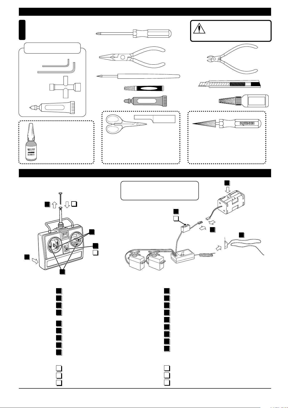
組立てに必要な工具
Tools required
4
キットに入っている工具
TOOLS INCLUDED
■六角レンチ
Hex Wrench
1.5mm
2mm
■十字レンチ
Cross Wrench
■グリス
Grease
GREASE
ロックタイト 中強度
LOCTITE Medium Strength
ビスの緩みを防ぎます。
To prevent the screws
from becoming loose.
No.94402
■+ドライバー(大、中、小)
Phillips Screwdriver (L.M.S)
■ラジオペンチ
Needle Nose Pliers
■キリ
Awl
■瞬間接着剤
Instant Glue
■ゴム系接着剤
Rubber Cement
ラウンドカッター&サンダー
ROUND CUTTER & SANDER
ボディのカット、仕上げ用。曲線部分も楽
に作業ができます。
For trimming bodies. Cutting along curved
lines never was so easy!
RUBBER
Instant Glue
No.1829
使用する工具の取扱いには、十分
注意してください。
CAUTION: Handle tools carefully!
注意
■ニッパー
Wire Cutters
■カッターナイフ
Sharp Hobby Knife
■ネジロック剤
Screw Cement
スペシャルテーパーリーマー
SPECIAL TAPER REAMER
下穴加工が不要で、直接1mm〜15mmの穴あけ
ができる工具です。
No need to pre-drill!
Drills neat 1mm to 15mm holes directly!
SCREW
CEMENT
No.80311
プロポの準備 RADIO PREPARATION
●プロポを下の順序にしたがってセットします。
Set up the radio control system as indicated below.
2
12
9
ON
7
11
OFF
1
▲送信機
6
Transmitter
●始める時
1
単3乾電池をセットする。(送信機)
アンテナをのばす。(送信機)
2
単3乾電池をセットする。(電池ボックス)
3
単3乾電池をセットした電池ボックスの
4
コネクターをつなぐ。
アンテナをのばす。(受信機)
5
トリムを中央にセットする。
6
スイッチを入れる。(送信機)
7
スイッチを入れる。(受信機)
8
スティックを動かしてサーボが動いているか確認。
9
※ スロットルのリバーススイッチをリバース側に
セットしてください。
Switch the reverse switch for both the steering
and the throttle.
ON
8
10
OFF
▲スイッチ
Switch
▲受信機
Receiver
▲サーボ
Servo
●START
1
Insert AA-size dry batteries. (Transmitter)
Extend the antenna. (Transmitter)
2
Insert AA-size dry batteries. (Battery Box)
3
Connect the battery box.
4
Extend the antenna. (Receiver)
5
Center the trims.
6
Switch on the transmitter.
7
Switch on the receiver.
8
Make sure the servos move according to
9
your transmitter inputs.
3
▲電池ボックス
Battery Box
4
5
●終わる時
スイッチを切る。(受信機)
10
スイッチを切る。(送信機)
11
アンテナを縮める。(送信機)
12
●FINISH
Switch off the receiver.
10
Switch off the transmitter.
11
Retract the antenna. (Transmitter)
12
3
Page 4
組立て前の注意(1) BEFORE YOU BEGIN (1)
組立てる前に説明書を良く読んで、おおよその構造を理解してから組立てに入ってください。
1
Read through the manual before you begin, so you will have an overall idea of what to do.
キットの内容をお確かめください。万一不良、不足がありましたら、お買い求めの販売店にご相談いただくか、当社「ユーザー相談室」までご連絡ください。
2
Check all parts. If you find any defective or missing parts, contact your local dealer or our Kyosho Distributor.
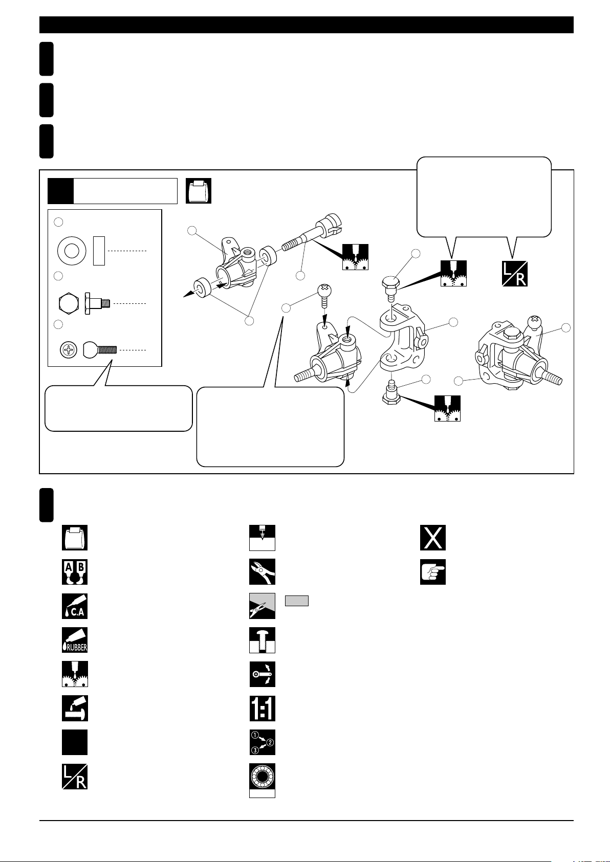
説明書の見かた
3
How to read the instruction manual:
〔説明例Example〕
説明書内では多くのマークが使用
フロントサスペンション
Front Suspension
1
4
5 x 10mm メタル
Metal Bushing
No.4, No.5, No.6
1
されています。マークに注意して
組立てを進めてください。
This instruction manual uses several symbols. Please note them
during the entire assembly.
4
キングピン
5
King Pin
4
5.8mm ピロボール(黒)
6
Pillow Ball (Black)
2
小物部品の名前、原寸図、使用数。
Key Number, Part Name, True-to-scale
Diagram, Quantity Used
説明書に使われているマーク
4
Symbols used throughout the instruction manual, comprise:
使用する袋詰。
Part bags used.
キット内の部品は、ビス類を除いてキー
No.が付けられています。スペアパーツを
購入する時はキーNo.を参照してください。
All parts except screws are identified by
key numbers. For purchasing spare parts,
find the key no. of the part needed in the
spare part list and refer to the left column
to look up the corresponding order no.
4
2mm
3
6
2mmの穴をあける(例)。
Drill holes with the specified
diameter (here: 2mm).
5
7
R
L
5
8
別購入品
Must be purchased separately!
2
x
エポキシ接着剤で接着する。
Apply epoxy glue.
瞬間接着剤で接着する。
Apply instant glue (CA glue, super glue).
ゴム系接着剤で接着する。
Apply rubber cement.
グリスを塗る。
Apply grease.
ネジロック剤を塗る。
Apply threadlocker (screw cement).
2セット組立てる(例)。
Assemble as many times as
2
specified (here: twice).
左右同じように組立てる。
Assemble left and right sides
the same way.
1901
余分をカットする。
Cut off excess.
をカットする。
Cut off shaded portion.
仮止め。
Tentatively tighten.
可動するように組立てる。
Ensure smooth non-binding
movement while assembling.
原寸図
True-to-scale diagram.
番号の順に組立てる。
Assemble in the specified
order.
オプションのベアリングの品番。
例:No.1901
Ball bearings are optional!
(with optional part no.)
注意して組立てる所。
Pay close attention here!
4
Page 5

組立て前の注意(2) BEFORE YOU BEGIN (2)
キットには、形や長さが違うビスや小物部品が多く入っています。説明書には原寸図がありますので確認してから組立ててください。
5
また、ビス類は多めに入っているものもありますので、予備としてお使いください。
This kit contains screws and hardware in different metric sizes and shapes.
Before using them, check the screws on the true-to-scale diagrams on the left side in each assembly step. Some screws are extras.
●ビスの種類 SCREWS
ビス Screw
キャップビス
Cap Screw
サラビス
Flat Head (F/H) Screw
TPビスは、部品にネジを切りながらしめつけるビスです。しめこみが固い場合がありますが、
6
部品が確実に固定されるまでしめこんでください。ただし、しめすぎるとネジがきかなくなり
ますので、部品が変形するまでしめないでください。
Self-tapping (TP) screws cut threads into the parts when being tightened. Excessive force may
permanently damage parts when tightening TP screws. It is recommended to stop tightening when
the part is attached or when some resistance is felt after the threaded portion enters the plastic.
TPビス
Self-tapping (TP) Screw
TPサラビス
TP F/H Screw
セットビス
Set Screw
●小物部品のサイズ例 OTHER HARDWARE
3x12mmビス
Screw
12mm
3x12mmサラビス
F/H Screw
3mm
12mm
3mmワッシャー・ナット
Washer・Nut
3mm
5x10mmメタル・ベアリング
Metal Bushing・Bearing
5mm
10mm
キット付属のエンジンには、混合気調整ネジ(低回転用)は装備されていません。
エンジンの取扱説明書とは一部異なります。
Included engine has no screws to adjust Air/Fuel Mixture at slow engine speed.
3mm
Correct
Wrong
しめすぎ
Overtightened.
E3Eリング
E-ring
3mm
6.8mmピロボール
Pillow Ball
6.8mm
ビスがきかない
The threads are stripped.
MEMO
5
Page 6
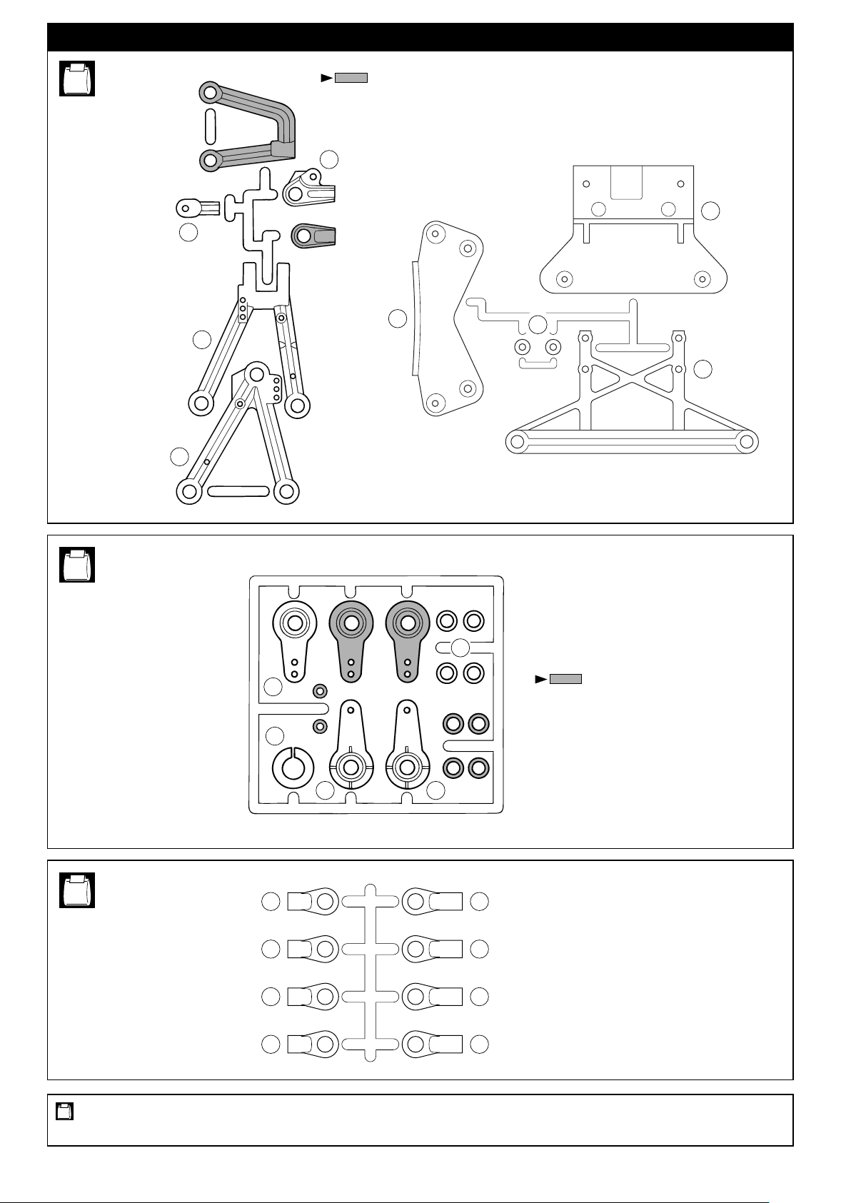
ランナー付プラパーツ配置図 /
ARRANGEMENT OF PLASTIC PARTS ON RUNNERS
No.2
16
11
20
部分の部品は、使用しません。
Shaded Parts are not used.
12
33
32
34
35
No.4
No.5
24
25
A B C
27 26
23
部分の部品は、使用しません。
Shaded Parts are not used.
4443
4443
使用する袋詰。
Part bags used.
6
4443
4443
Page 7
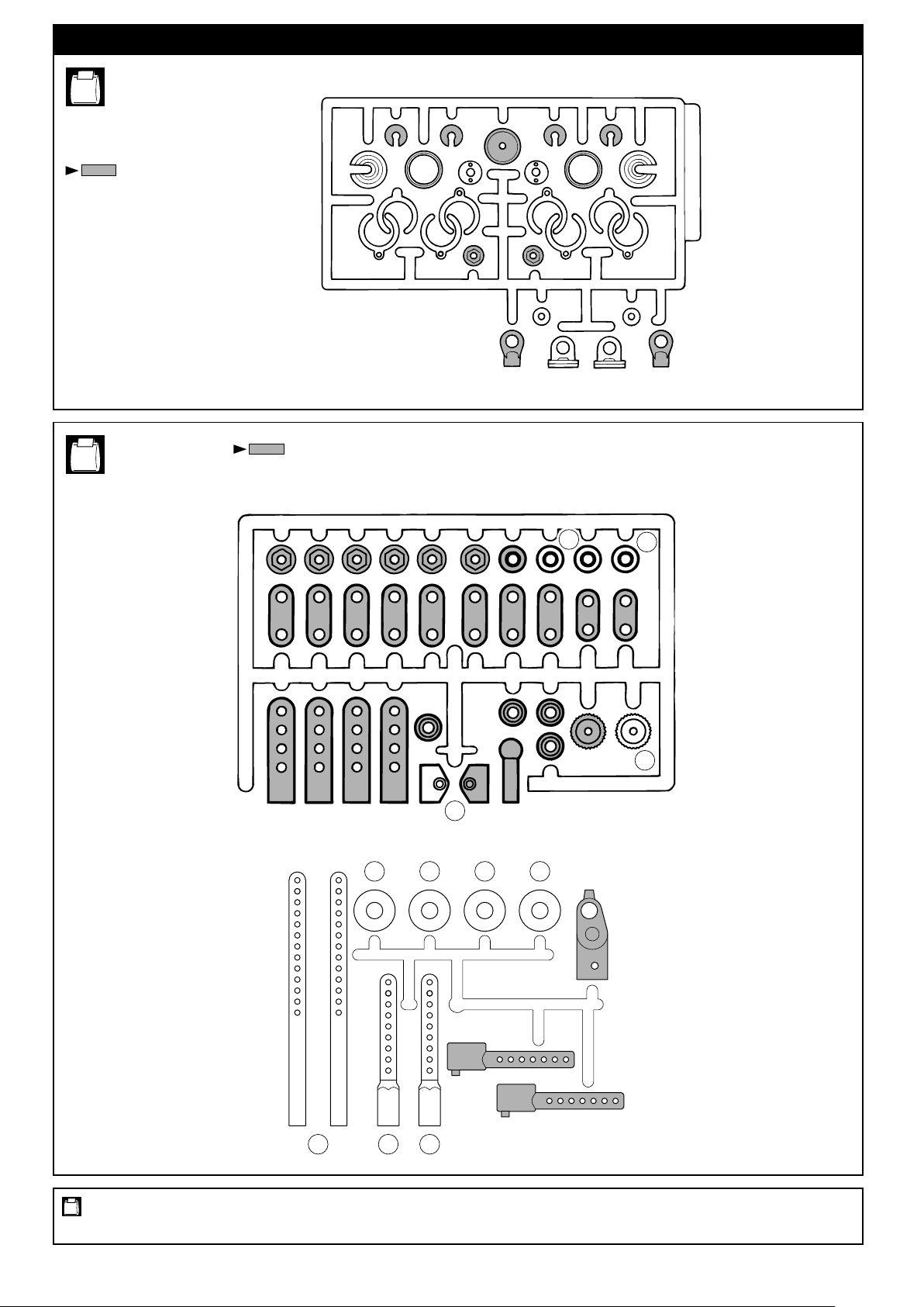
ランナー付プラパーツ配置図 /
No.5
ARRANGEMENT OF PLASTIC PARTS ON RUNNERS
部分の部品は、使用しません。
Shaded Parts are not used.
部分の部品は、使用しません。
No.7
Shaded Parts are not used.
G-6
G-4
G-1 G-1
G-4
G-8 G-8
G-3 G-3
66
G-6
G-5G-5
66
使用する袋詰。
Part bags used.
67
62
39 39 39 39
383840
7
Page 8
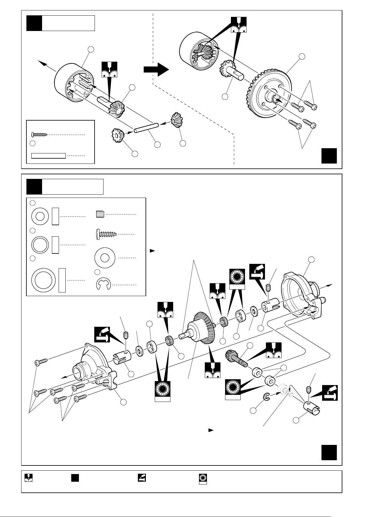
デフギヤ
Differential Gear
1
101
105
2x8mm
102
102
2 x 8mm
TP Screw
104
2
3 5 x 10mm
110
109
TPビス
3 x 20mm
Shaft
Metal Bushing
8 x 10mm
Metal Collar
10 x 14mm
Metal Bushing
シャフト
ギヤボックス
Gearbox
メタル
メタルカラー
メタル
8
2
4 x 4mm
Set Screw
4
3 x 10mm
TP Screw
5mm
4
Washer
112
4
セットビス
ワッシャー
E4
Eリング
E-ring
TPビス
103
12
104
6
平らな面にセットビスを固定する。
Firmly tighten the set screws onto
4
the flat spots.
2
103
96999
4x4mm
2x8mm
107
x
2
3x10mm
Apply grease.
3x10mm
x
2
Assemble as many
times as specified.
4x4mm
106
5mm
108
109
110
デフギヤ
Differential Gear
96999
ネジロック剤を塗る。2セット組立てる(例)。グリスを塗る。
Apply threadlocker
(screw cement).
5mm
109
110
96996
111
112
平らな面にセットビスを固定する。
Firmly tighten the set screws onto
the flat spots.
オプションのベアリングの品番。
Ball bearings are optional !
96999
(with optional part no.)
108
3
4x4mm
108
x
2
8
Page 9
フロントサスペンション
Front Suspension
3
3 x 10mm
TP F/H Screw
TPサラビス TPサラビス
向きに注意。
Note the direction.
3 x 12mm
TP F/H Screw
2
前
Front
2
3x10mm
3x12mm
113
114
115
3x10mm
センターギヤボックス
Center Gearbox
4
3 x 6mm
TP Screw (Silver)
3 x 10mm
TP Screw (Silver)
3 x 30mm
Screw
104
3 x 20mm
Shaft
122
18mm
Aluminium Spacer
TPビス(銀)
TPビス(銀)
ビス
シャフト
1
アルミスペーサー
センターギヤボックス
Center Gearbox
5
4 x 4mm
Set Screw
3 x 8mm
Screw
125
セットビス
2
ビス
2
ブレーキピストン
Brake Piston
1
1
2
110
8 x 10mm
Metal Collar
1
109
10 x 14mm
Metal Bushing
1
123
フロント側
Front
メタルカラー
メタル
2
2
118
104
3x30mm
3x6mm
3x10mm
4x4mm
117
119
116
110
109
120
は向きに注意。
128
Note the direction for .
上
Top
向きに注意。
Note the direction.
96999
128
122
110
約4.5mm
approx. 4.5mm
109
121
96999
4x4mm
124
平らな面にセットビスを固定する。
Firmly tighten the set screws onto the flat spots.
ネジロック剤を塗る。
Apply threadlocker
(screw cement).
可動するように組立てる。
Ensure smooth non-binding
movement while assembling.
128
126
128
108
3x8mm
注意して組立てる所。 グリスを塗る。オプションのベアリングの品番。
Pay close attention
here!
96996
(with optional part no.)
125
Apply grease.Ball bearings are optional !
9
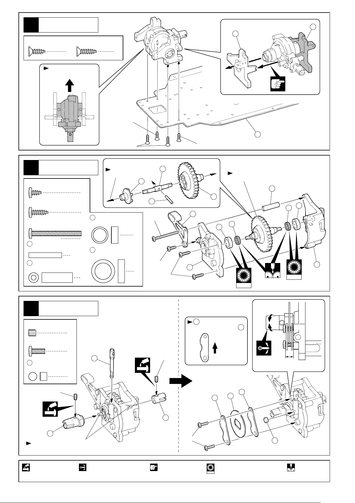
Page 10

センターギヤボックス
Center Gearbox
6
3 x 10mm
TP F/H Screw
7
3 x 10mm
TP F/H Screw
3 x 10mm
TP Screw
TPサラビス
リヤギヤボックス
Rear Gearbox
TPサラビス
4
TPビス
2
4
129
2
3
1
3x10mm
3x10mm
前
向きに注意。
Note the direction.
127
1
2
3
Front
フロントサスペンション
Front Suspension
8
3 x 10mm
TP F/H Screw
TPサラビス
131
3x10mm
3x10mm
(サラ)
(F/H)
130
3x10mm
3x10mm
(サラ)
(F/H)
132
133
4
番号の順に組立てる。
Assemble in the specified order.
10
3x10mm
3x10mm
Page 11

組み立て開始
START
フロントサスペンション
Front Suspension
9
10
4 x 40mm
Adjustable Rod
3 x 10mm
TP Screw
3 x 15mm
F/H Screw
4mm
Flanged Nylon Nut
3 5 x 10mm
7
5.8mm
Pillow Ball
6
アジャスタブルロッド
TPビス
サラビス
フランジ付ナイロンナット
メタル
Metal Bushing
ピロボール
布などでキズを防ぐ。
Take care balls from
any damage when
assemble.
Bマークのあるもの
"B" marked
9 6.8mm
2
2
4
2
4
4
13
15
7.8mm
Flange Ball
4 x 20mm
17
Set Screw
8
6.8mm
Ball End
No.1,
No.2
ボール
Ball
7.8mm
ボール
Ball
座付ボール
セットビス
ボールエンド
向きに注意。
Note the direction.
外側内側
OutsideInside
1
10
2
3
96996
96996
3
4
4mm
5
Aマークのあるもの
"A" marked
約19mm
approx. 19mm
3x10mm
向きに注意。
Note the
direction.
3x15mm
12
13
しめすぎない
ようにする。
Do not
overtighten.
4
4
4
2
7
8
9
4
11
8
9
約3mm
approx. 3mm
17
左側用
7
Left
フロントサスペンション
Front Suspension
10
3 x 15mm
TP Screw
3 x 8mm
F/H Screw
3 x 18mm
F/H Screw
134
Oリング
O-ring
TPビス
サラビス
サラビス
1mm
13
右側用
Right
15
16
No.1,
No.2
右側用
2
134
4
2
3
Right
左側に2個Oリングを
入れ、右側に1個Oリ
ングを入れる。
Put 2 O-rings on the left side.
Put 1 O-rings on the right side.
内側の穴を使用。
Use inside hole.
3x8mm
3x15mm
34
3x18mm
左側用
Left
しめすぎない
ようにする。
Do not
overtighten.
(サラ)
(F/H)
使用する袋詰。
Part bags used.
Ensure smooth non-binding
movement while assembling.
左右同じように組立てる。
Assemble left and right
sides the same way.
注意して組立てる所。可動するように組立てる。
Pay close attention here!
3x15mm
グリスを塗る。
Apply grease. Apply threadlocker
仮止め。
Tentatively tighten.
ネジロック剤を塗る。 オプションのベアリングの品番。
(screw cement).
Ball bearings are optional !
96996
(with optional part no.)
11
Page 12

リヤサスペンション
Rear Suspension
11
3 x 15mm
TP Screw
4mm
Flanged Nylon Nut
3 5 x 10mm
Metal Bushing
7
5.8mm
Pillow Ball
8
6.8mm
Ball End
TPビス
フランジ付ナイロンナット
メタル
ピロボール
ボールエンド
66
テーパーワッシャー
Tapered Washer
2
2
布などでキズを防ぐ。
Take care balls from any
4
2
4
damage when
assemble.
No.1, No.2,
No.3, No.7
2
9
14
向きに注意。
Note the direction.
1
2
96996
3
19
左側用
Left
3
96996
外側内側
OutsideInside
4
4mm
9
8
9 6.8mm
15
21
ボール
Ball
7.8mm
座付ボール
Flange Ball
スクリューハブピン
Screw Hub Pin
18
右側用
Right
10 150
リヤサスペンション
Rear Suspension
12
8
4
約12.5mm
4
approx. 12.5mm
取付穴
Use this hole.
左側用
Left
66
2
3x15mm
7
1mm
15
21
No.1
15
右側用
Right
20
3 x 15mm
TP Screw
3 x 8mm
F/H Screw
134
Oリング
O-ring
使用する袋詰。 注意して組立てる所。可動するように組立てる。
Part bags used. Pay close attention here!
TPビス
サラビス
Ensure smooth non-binding
movement while assembling.
2
4
2
内側の穴を使用。
Use inside hole.
左右同じように組立てる。
Assemble left and right
sides the same way.
12
右側にも使用。
134
Use O-rings for both side.
3x8mm
グリスを塗る。
Apply grease. Apply threadlocker
内側の穴を使用。
Use inside hole.
3x15mm
左側用
Left
仮止め。
Tentatively tighten.
ネジロック剤を塗る。 オプションのベアリングの品番。
(screw cement).
Ball bearings are optional !
96996
(with optional part no.)
Page 13

13
ステアリング
Steering
No.1, No.4
2.6x6mm
2.6 x 6mm
Screw
7
5.8mm
Pillow Ball
3mm
Nylon Nut
23
5x8x2.5mm
Plastic Bushing
14
ビス
ピロボール
ナイロンナット
プラメタル
ステアリング
Steering
2
六角レンチ(小)
Hex Wrench (small)
22
2
96997
1
23
28
Cのマーク
“C” marked
27
7
4
23
96997
7
マイナスドライバー
で広げて入れる。
Widen the slit with
a screwdriver and
fit in the snap.
24
3mm
23
96997
23
41
25
26
96997
No.1,
No.4
29
5.8mm
Ball End
3023 x 20mm
Set Screw
ボールエンド
セットビス
29
10 200
バンパー
Bumper
15
3 x 8mm
Screw
ビス
4
30
3x20mm
約10.5mm
approx. 10.5mm
2
29
x
2
No.1, No.4
3x10mm
31
3x8mm
31
3 x 10mm
TP Screw
使用する袋詰。
Part bags used.
TPビス
2
可動するように組立てる。 オプションのベアリングの品番。
Ensure smooth non-binding
movement while assembling.
Ball bearings are optional !
96997
(with optional part no.)
2セット組立てる(例)。
x
2
Assemble as many
times as specified.
13
Page 14

ダンパー
Shock
16
43
5.8mm
ボールエンド(M)
Ball End (M)
78
ダンパーシャフト
Shock Shaft
77
E2.5
Eリング
E-ring
44
5.8mm
ボールエンド(L)
Ball End (L)
No.5
43
x
4
44
約13.5mm
approx. 13.5mm
44
x
4
77
77
79
ダート走行時には、 5.8mm
ボールエンド(L)を使用する。
Use 5.8mm Ball End (L) at
the time of driving on off-road.
シャフトに布をまき、つかむ。
Cover the shaft with cloth before
gripping it with pliers.
4
G1
4
8
78
4
17
18
ダンパー
Shock
オイル
Oil
ダンパー
Shock
No.5
80
ピストンを下げ、
オイルを図の位置
まで入れる。
Pull down the piston
0 ~ 1mm 0 ~ 1mm
ピストン
Piston
and slowly fill in oil.
ゆっくり上下させ、
気泡をとる。
Then, gently move
the piston up and
down to get rid of
air bubbles.
No.5
G3
81
79
もう一度図の位置
までオイルを足す。
Add oil one more
time up to the brim.
を にかぶせ、あふれた
81
79
オイルをふきとり、 G3を
組立てる。
Put onto , wipe up any
81
excess oil and screw on G3
together with .
80
79
80
スプリングを縮めてG6を入れる。
Compress the spring and install G6.
スムーズに動くか確認する。
スムーズに動かないときは、
オイルを入れ直す。
Ensure smooth piston
move-ment.
x
4
83
5.8mm
ボール
Ball
3 x 18mm
F/H Screw
使用する袋詰。
Part bags used.
サラビス
82
14
4
4
フロント用は4mm、リヤ用は2mm
のスペーサーを使用します。
Use 4mm spacer for Front and
2mm spacer for Rear.
G5
G4
4セット組立てる(例)。
x
4
Assemble as many times as specified.
2~4mm
G6
G8
83
3x18mm
x
4
Page 15

フロントダンパー
Front Shock
19
20
21
リヤダンパー
Rear Shock
No.5
左のみ1mmスペーサーを足す。
Install 1mm spacer only the left.
バンパー
Bumper
取付穴
Use the upper hole.
No.1,No.2
3x10mm
33
32
3 x 10mm
TP Screw
使用する袋詰。
Part bags used.
TPビス
3x12mm
一度はずして と一緒
に取付ける。
4
左右同じように組立てる。
Assemble left and right sides the same way.
Remove both screws and
reinstall together with .
3x10mm
32
37
32
注意して組立てる所。
Pay close attention here!
15
Page 16

燃料タンク
Fuel Tank
22
46
シリコンチューブ
Silicone Tube
210mmにカットする。
Cut to one 210mm piece.
3 x 10mm
TP F/H Screw
TPサラビス
No.1, No.6
46
シリコンチューブ
Silicone Tube
110mmにカットする。
Cut to one 110mm piece.
45
で使用。
46
210mm 110mm
2
3x10mm
31
Use in .
31
5mm
23
エンジン
Engine
No.1
9080706050403020100
紙1枚分のすき間をつくって
固定する。
Tighten the screws with
one sheet of paper inserted
between both gears.
120 130 140 150 160 170 180110100
エンジンアッセンブリー
Engine Assembly
付属のエンジンには混合気調整
ネジ(低回転用)はありません。
Included engine has no screws
to adjust Air/Fuel Mixture at
slow engine speed.
3 x 8mm
Screw
使用する袋詰。
Part bags used.
16
ビス
3x8mm
3
余分をカットする。
Cut off excess.
3x8mm
Page 17

24
マフラー
Muffler
No.1, No.6
前から見た図
Front View
51
115
3 x 30mm
Screw
3 x 8mm
F/H Screw
ビス
サラビス
4x4mm
2
1
マフラーが 燃料タンク・
51
メインシャシーと接触しない
115
ように取り付ける。
Assemble muffler like the picture.
45
45
51
4x4mm
53
46
52
49
50
46
49
3mm
48
47
4 x 4mm
Set Screw
3mm
Nut
25
3 x 10mm
TP Screw
3 x 10mm
TP F/H Screw
3x10mm
セットビス
座付ナット
プロポ
Radio
TPビス
TPサラビス
3x10mm
10
2
3x8mm
2
スロットルサーボ
No.1, No.7
ステアリングサーボ
Steering Servo
2
Throttle Servo
3x30mm
54
使用する袋詰。
Part bags used.
x
2
余分をカットする。
Cut off excess.
54
3x10mm
別購入品。
Must be purchased separately!
3x10mm
(サラ)
(F/H)
2セット組立てる(例)。
x
2
Assemble as many times as specified.
3x10mm
3x10mm
(サラ)
(F/H)
17
Page 18

26
プロポ
Radio
No.7
スイッチ
Switch
プロポ
Radio
27
3 x 10mm
TP F/H Screw
TPサラビス
受信機用電池ボックス
Receiver Battery Box
55
アンテナ
2
Antenna
No.1
スイッチ
Switch
スイッチ
Switch
プロポの説明書を参考に、コネクター
を接続する。
Connect as per radio instruction manual.
受信機
Receiver
プロポ
Radio
28
2 x 8mm
TP Screw
57
TPビス
フックピン
Hook Pin
3x10mm
3x10mm
No.1, No.7
3
57
1
2x8mm
58
アンテナ
Antenna
2x8mm
56
コードを挟まない
ように注意。
Make sure to place
the cord inside of
the box.
使用する袋詰。
Part bags used.
18
注意して組立てる所。別購入品。
Pay close attention here!Must be purchased separately!
Page 19

プロポ
Radio
29
59
ステアリングロッド
Steering Rod
3 x 3mm
Set Screw
セットビス
No.1, No.7
Supplied with the servo.
59
1
2
1
3x3mm
サーボ付属
1
3
90
90
プロポ
Radio
30
No.1, No.7
2 x 8mm
TP Screw
3 x 3mm
Set Screw
60
61
63
64
TPビス
セットビス
2mm
Stopper
スプリング
Spring
スロットルロッド
Throttle Rod
ブレーキロッド
Brake Rod
ストッパー
4
2mm
20mm
少し曲げる。
Bend.
2x8mm
1
2
63
2
1
1
64
3x3mm
サーボホーン
Servo Horn
60
3x3mm
61
62
2mm
使用する穴。
The hole used.
60
約14mm
approx.14mm
上下の向きに注意。
Note the top
and bottom.
使用する穴。
Holes used.
約10mm
approx.10mm
約16mm
approx.
16mm
1
67
サーボ付属
2
3
1
65
66
46
シリコンチューブ(5mm)
Silicone Tube (5mm)
可動するように組立てる。
Ensure smooth non-binding movement while assembling.
True-to-scale diagram.
プロポ
Radio
31
3 x 3mm
Set Screw
66
65
セットビス
テーパーワッシャー
Tapered Washer
ブレーキレバー
Brake Lever
No.1, No.7
下の穴に通す。
Link to the
1
1
1
65
向きに注意。
Note the direction.
6mm
bottom hole.
Supplied with the servo.
4
3x3mm
66
使用する袋詰。
Part bags used.
をカットする。 2mmの穴をあける(例)。 原寸図。
Cut off shaded portion. Drill holes with the specified diameter.
別購入品。
Must be purchased separately!
注意して組立てる所。 仮止め。
Pay close attention here! Tentatively tighten.
番号の順に組立てる。
Assemble in the specified order.
2mm
中立
Neutral
90
5
19
Page 20

スロットルリンケージ調整
Throttle Linkage Adjustment
32
( )
( Neutral )
約1mm
approx.1mm
スロットルスト
ップスクリュー
で調整する。
Adjust with throttle
stop screw.
a
スロットルストップスクリュー
Throttle Stop Screw
ブレーキが効きはじめる位置。
Position where brake starts working.
a,bのセットビスで図のようにする。
Set up a and b screws as shown.
約1mm
approx.1mm
ちぢんでいる。
Contracted.
No.7
( )
ハイニュートラル
( High )
( )
ブレーキ
( Brake )
ブレーキの効き
を確認する。
Brake works
properly ?
b
84
85
87
8686
72
キャブレターが全開になるか、確認する。
Carburetor open fully ?
確認後、とりつける。
Confirm the setting
before installation.
オフロード走行時にはエアー
クリナーをNo.39645エアーク
リナー(別売)に交換して下さい。
Replace air cleaner to
No.39645 Air Cleaner
(option) at the time of
driving on off-road.
フロントボディマウント
Front Body Mounts
33
2 x 8mm
TP Screw
3 x 10mm
TP Screw
TPビス
TPビス
リヤボディマウント
Rear Body Mounts
34
2.6 x 6mm
TP Screw
3 x 15mm
TP Screw
725.8mm
Pillow Ball
TPビス
TPビス
ピロボール
2x8mm
No.1,No.7
39
38
39
2
2
2x8mm
3x10mm
No.1,No.2
39
39
2x8mm
No.6,No.7
2.6x6mm
70
2
29
4
3x73mm
29
約60mm
approx. 60mm
2x8mm
3x15mm
40
3x15mm
35
29
5.8mm
Ball End
70
3 x 73mm
Rod
使用する袋詰。
Part bags used.
20
ボールエンド
ロッド
2 x 8mm
2
TP Screw
1
余分をカットする。
Cut off excess.
TPビス
2
7
6050403020100
左右同じように組立てる。 をカットする。
Assemble left and right sides the same way.
Cut off shaded portion.
7
2.6x6mm
76
Page 21

35
タイヤ
Wheels
68
向きに注意。
Note the direction.
42
x
右側用
For Right
2
69
ホイールを回しながら半分くらいタイヤにいれる。 タイヤを強くひっぱりホイールを押しこむ。
Fit wheels inside tyres as shown. Twist the tyre onto the wheel.
タイヤ
Wheels
36
六角レンチでシャ
フトを固定しなが
らナットをしめる。
Hold the shaft tight
with a hex wrench
to tighten the nut.
No.1
< Front >
フロント
4mm
左側用
For Left
x
2
ピッタリはめてからタイヤとホイールのつなぎ目に
瞬間接着剤を流し接着する。
After fitting wheels to tyres, apply instant glue as shown.
< Rear >
リヤ
リヤ用
For Rear
4mm
37
ボディ
Body Shell
フロント用
For Front
6mm
3mm
十字レンチ
Cross Wrench
一度シャシーからはずして使用する。
Remove this nut from the chassis
and fasten the tire with it.
6mm
3mm
3mm
十字レンチ
Cross Wrench
6mm
3mm
ゴム系接着剤で接着する。 をカットする。
Apply rubber type glue. Cut off shaded
瞬間接着剤で接着する。
Apply instant glue
(CA glue, super glue).
2セット組立てる(例)。
x
2
Assemble as many
times as specified.
左右同じように組立てる。
Assemble left and right
sides the same way.
portion.
6mmの穴をあける(例)。
6mm
Drill holes with the
specified diameter.
21
Page 22

塗装
Painting
38
塗装前に、洗剤で油やよごれを洗う。 ウインドウ部分に、
1
Before painting, use a neutral detergent
to remove any oil residues and dirt.
2
内側からマスキング
シートを貼る。
Mask the windows
from the inside.
塗分けはパッケ
3
ージ写真も参考
にしてください。
Refer to the pictures
on the box for the
color scheme.
京商スプレーカラーでボディ内側を塗装する。
Paint the body shell from the inside using Kyosho’s spray colors.
No.76321
マスキング
Mask Windows
イタリアンレッド
Italian Red
イタリアンレッド
Italian Red
塗装後、ボディ表面の保護ビニ
4
ールシートをはがしておく。
After painting, remove the
protective film from
the body shell.
イタリアンレッド
Italian Red
マスキング
Mask Windows
イタリアンレッド
Italian Red
ボディ
Body Shell
39
3 x 8mm
Screw
3mm
Washer
3mm
Nut
ビス
ワッシャー
ナット
3x8mm
4
8
4
3mm
3mm
3mm
3mm
3mm
3x8mm
3mm
22
Page 23

デカール
Decals
40
22 21171920
1
2623 30 31 29 35 32 34 3325
カッコの中は反対側用のデカールナンバーです。図の位置にから順にデカールをはる。
The decal numbers between brackets are only for the opposite side.Apply the decals to the positions indicated in numerical order.
61
16 14 151813
2
12
1
56 575859 59
9
ボディ
Body Shell
41
27 28 312426
( )
3 4
1011 6013
No.1
3738
57
( )
39 40
50 51 52 5349 49 54 55
8 5
( )
46 4748 43 4345 44
343635
( )
41 42 62
( )
6 7
57
57
57
ボディピン
Body Pin
走行上の注意
Safety Precautions
使用する袋詰。
Part bags used.
57
4
走行時は、必ずボディを装着してください。
下記の場所での走行は、故障の原因になりますのでおやめください。
・シャシーにからむような草の生えているところ。
・泥地、砂地、砂利の多いところ。
定期的に、各部のビス類が緩んでないか確認してください。
ボディピンは、図のように曲げて
おくと取り外しが楽です。
Slightly bend the body pins as shown
in the diagram for easier removal.
Always run your car with the body shell mounted!
Do not run your car on ground:
• that is overgrown with grass.
• that is muddy, sandy or rocky.
Check all screws, nuts etc. on a regular basis for looseness.
23
Page 24

取扱いの注意 OPERATING YOUR MODEL SAFELY
事故やケガ等の危険防止のため、次のことを必ずお守りください。
In order to avoid accidents and personal injury, be sure to observe the following:
●燃料の蒸気、排気ガスは有害ですので、必ず屋外で取
扱ってください。
Since exhausts and fuel vapors are noxious to health,
use fuel only outdoors!
●ケガの恐れがあるので、回転部分に手や物を入れない
ようにしてください。
Keep hands and objects away from rotating engine
parts to avoid personal injury.
●エンジンは、停止後でも本体やマフラー周辺は高温に
なっているので、ヤケドに注意してください。
Because after running the engine, the engine and the
muffler are extremely hot, beware of getting burned!
●燃料は模型用グロー燃料を必ず使用してください。ガ
ソリンや灯油の使用は、火災等の事故の恐れがありま
す。絶対に使用しないでください。
Only use glow fuel for radio control models! Never use
gasoline or kerosene which might cause accidents
such as fires!
●燃料は引火性がありますので、火気のあるところや室
内では絶対に使用しないでください。また、空缶は火
中には投げ入れないでください。爆発の恐れがあります。
Because fuel is highly inflammable, never use fuel
indoors, near any source of heat, open flames or even
sparks! Do not dispose of an empty fuel can into a fire.
It might explode causing serious injury!
●燃料は間違って 飲んだり目に入ると有害です。万一
事故が起きた場合は、吐かせる、洗眼するなどをした
後すぐに医師の診察をうけてください。
Be particularly careful not to swallow fuel or to get fuel
into eyes! Nevertheless, should fuel be swallowed,
immediately induce vomiting and call a physician.
Should fuel get into eyes, thoroughly rinse the eyes
and seek medical advice.
●次のような時、場所では走行させないでください。思
わぬ事故の原因となります。
For accident prevention, do not run your model under
the following circumstsnces:
人が多い場所。
In place where many people gather.
家、学校、病院などの近く。
Near residential districts, schools and hospitals.
道路、線路、電線の近く。
Near roads, railroads, air corridors and electric lines.
同じバンドの無線操縦模型が近くにいる時。
Also make sure that nobody is using the same
frequency as you do at the same time!
プロポの電池が少ない時。
When the radio batteries are empty.
車の動きがおかしい時。
When the model's control or running behavior is
strange.
●燃料はキャップをしっかりしめ、幼児の手の届かない
冷暗所に保管してください。
Always store fuel in a safe place out of children's reach
with the cap shut tight! The place for storage should be
dark, cool and dry!
24
Page 25

品番
No.
6.8mmボール
BS46
6.8mm Ball
クラッチシュー(DX)
BS125
Clutch Shoe (DX)
サーボセイバー
BV5
Servo Saver
フライホイールセット
FD21
Flywheel Set
燃料チューブ
FD29
Fuel Tube
GP用リンケージセット
FD65
Linkage Set (for GP cars)
クラッチベル(15T)
Clutch Bell (15T)
サスアームセット
FT5
Suspension Arm Set
ナックルアーム
FT11
Knuckle Arm
ボディマウント
Body Mount
ギヤボックス
FZ10
Gear Box
ファイナルデフケース
FZ13
Final Differential Case
スイングシャフト
Swing Shaft
センターバルクヘッド
FZ58
Center Bulkhead
スパーギヤ(39T)
FZ62
Spur Gear (39T)
ディスクホルダー
FZ63
Disk Holder
スパーギヤシャフト
FZ64
Spur Gear Shaft
ブレーキレバー
FZ70
Brake Lever
リヤハブキャリア
LA28
Rear Hub Carrier
5.8mmボールエンド
LA43
5.8mm Ball End
クラッチベアリング
LD70
Clutch Bearing
パイロットシャフト
GT5
Pilot Shaft
ジョイント
OT5
Joint
デフギヤセット
OT28
Differential Gear Set
Oリング
OT29
O-ring
エアーフィルター(AB15)
Air Filter (AB15)
メインシャシー
TR1B
Main Chassis
フロントバルクセット
TR2
Front Bulk Set
リヤバルクセット
TR3
Rear Bulk Set
ステアリングプレートセット
TR5
Steering Plate Set
メカボックス
TR6
Receiver Box
アッパーロッド(S)
TR8
Upper Rod (S)
バンパー,リヤボディマウント
TR10
Bumper, Rear Body Mount
ホイールシャフト
TR11
Wheel Shaft
サーボセイバー強化リング
UM43
Servo Saver Reinforcing Ring
VZ022
ウレタンバンパー(ブラック)
BK
Urethane Bumper (Black)
ダンパーエンド(M,L)
W5130
Shock End (M,L)
レーシングダンパー(SS)
W5161
Racing Shock (SS)
パーツ名
Part Names
スペアパーツ SPARE PARTS
内容(キーNo.と入数)
Quantity
9 x 10
144
x 2
x 1
x 1
x 4
x 1
x 239x 4
x 1
x 1
x 1
x 1
123 125
x 1
x 12
x 1
x 1
x 2
x 2
x 10
x 1
131130
126
x 1
x 1
x 2
x 2
x 1
x 4
x 4
112
x 1
x 1
x 1
x 1
x 1
62 67
x 2
x 1
x 1
104
x 1
x 1
31
x 4
54
x 2
34
23
x 1
x 4
x 2
x 4
x 2
x 2
143
24 25 2726
141
46
22 59 63 6461
60 66
147
11 12 2016
5 6 x 1
38 40
106 107
101 105 111
1 x 2
116 120 122121
118 119
124
104 117
65
18 19
29
146 148
142
108
102 103
134
84 85 8786
115
113 114 133132
76
28
55 56
14
32 3533
2 x 2
41
37
43 44
78 79 81 82 8380
77
★定価
250
500
300
650
120
1100
1100FM222
700
300
400FT22
300
900
500FZ19
350
300
400
250
300
180
300
580
400
300
750
200
250RM11
1200
650
600
450
600
300
400
400
100
400
200
1200
★発送
手数料
200
(一律)
★FOR JAPANESE MARKET ONLY.
品番
No.
1165
1167
1245-073
1284
1296
1700
KP/KY
1701
KP/KY
1705
1916
1918
6591
39192
39192-1
74901
92031
92041
92301
92418
92451
92545
92601
BK
92638
92639
92645
92696
92831
92843
92846
92971
92972
キットの部品の一部にはスペアパーツとして販売していない物があります。
京商ではオプションパーツを販売していますのでお買い求めください。
Some of the parts included are not available as spare parts. Purchase
optional parts instead.
パーツ名
Part Names
3x20mmセットビス
3x20mm Set Screw
4x20mmセットビス
4x20mm Set Screw
5.8mmスイングシャフト(73mm)
5.8mm Swingshaft (73mm)
5.8mmピロボール
5.8mm Pillow Ball
6.8mmボールエンド
6.8mm Ball End
蛍光ストラップ(S)
Fluorescent Strap (S)
蛍光ストラップ(M)
Fluorescent Strap (M)
アンテナパイプ(白)
Color Antenna (White)
5x10mmメタル
5x10mm Metal Bushing
8x14mmメタル
8x14mm Metal Bushing
マフラーガスケット
Muffler Gasket
ボディセット(三菱ランサーEVO.VII)
Body Set (MITSUBISHI LANCER EVO.VII)
デカール(三菱ランサーEVO.VII)
Decal Set (MITSUBISHI LANCER EVO.VI)
GS15Rエンジン
GS15R Engine
3x72mmロッド
3x72mm Rod
マフラーポストセット
Muffler Post Set
燃料タンク 75cc
75cc Fuel Tank
スクリューハブピン
Screw Hub Pin
ロープロハイグリップタイヤ
Low Profile High-Grip Tire
ロープロホイール(5スポーク)
Low Profile Wheel (5-spoke)
耐熱マフラージョイントパイプ
Heat-resistant Muffler Joining Pipe
スナップピン
Snap Pin
スチールドライブワッシャー(3t)
Steel Drive Washer (3t)
スイングシャフト(OT6)
Swingshaft (OT6)
ディスクブレーキパッド
Disk Brake Pads
4x40mmロッド
4x40mm Rod
7.8mm座付ボール
7.8mm Flanged Ball
7.8mmボール
7.8mm Ball
SSチューンドマフラー
SS Tuned Muffler
マニホールド
Manifold
内容(キーNo.と入数)
Quantity
30
x 3
17
x 3
129
x 2
7 x 8
8 x 12
72
x 10
49
x 10
58
x 6
3 x 10
109 110
x 10
47
x 5
ボディ デカール 一式
body, decals
デカール
decals
150
70
52 53
45
21
68 69
42
50
57
4 x 4
127
128
10
15
13
51
47 48
x 1
x 1
x 2
x 1
x 1
x 4
x 2
x 2
x 2
x 10
x 2
x 2
x 2
x 4
x 10
x 1
x 1
★定価
200
200
700
200
400
180
250
500
400
600
200
4200
2000
13000
300
300
1000
200
1200
600
800
200
300
500
300
200
500
400
1200
600
★発送
手数料
200
(一律)
25
Page 26

品番
No.
FD20
FD49
FZW13
FZW15
FZW18
FZW30
FZW56
FZW67
KC45
SPW51
TRW1B
TRW2
W5155
1295
KP/KY
1706
1707
1708
1710
1795
KP/KY
1948
39011
39308
39509
39641
39645
39648
39671
39712
39735
71161
74901
-14BL
パーツ名
Part Names
エンジンマウント
Engine Mount
フライホイール(CZ-R)
Flywheel (CZ-R)
スチールデフベベルギヤ
Steel Differential Bevel Gear
スチールデフピニオンギヤ
Steel Differential Pinion Gear
スチールデフギヤセット
Steel Differential Gear Set
4サイクルフィッティングキット
4-cycle Fitting Kit
2スピードオートマチックトランスミッションセット
2-Speed Automatic Transmission Set
ブレーキングセンターワンウェイ
Braking Center Oneway
スペシャルクラッチ
Special Clutch
ステンレスディスクローター
Stainless Disk Rotor
SPメインシャシー
Special Main Chassis
ベアリングセット
Ball Bearing Set
アジャスタブルテフロンダンパー(SS)
Adjustable Teflon Shock (SS)
5.8mmボールエンド
5.8mm Ball End
カラーアンテナ(ピンク)
Color Antenna (Pink)
カラーアンテナ(イエロー)
Color Antenna (Yellow)
カラーアンテナ(黒キャップ付)
Color Antenna (Black Cap)
スペシャルアンテナホルダー
Special Antenna Holder
カラーシリコンチューブ
Color Silicone Tube
エアークリーナーオイル
Air Cleaner Oil
スーパーチューンドサイレンサーRセット
Super Tuned Silencer R Set
燃料フィルター(M)
Fuel Filter (M)
スチールファイナルデフケース
Steel Final Differential Case
クーリングファンセット
Cooling Fan Set
エアークリーナー
Air Cleaner
スペシャルエンジンマウント
Special Engine Mount
ベスペル®クラッチシュー
Vespel® Clutch Shoe
SCスーパーチューンドマフラー
Spring Connect Super Tuned Muffler
サーボセイバー強化スプリング
Servo Saver Reinforcing Spring
6v X-FORCE 600ニカドバッテリー
6v X-FORCE 600 Ni-Cd Battery
SPシリンダーヘッド(GS-15R)
SP Cylinder Head (GS-15R)
オプションパーツ OPTIONAL PARTS
内容(キーNo.と入数)
Quantity
別売エンジン取り付け用
for optional engine
O.S.エンジンCV系用
for O.S. CV type engine
強化タイプギヤ
strengthened gear
強化タイプギヤ
strengthened gear
スチールタイプデフギヤ一式
Steel type Differential Gear
4サイクルエンジン搭載用
When Mounting 4-cycle Engines
オンロード専用
Only for on road.
FZW56専用
Only for FZW56.
と交換
143
instead of .
ハイパフォーマンスディスクローター
high performance disk rotor
と交換
115
instead of .
5x10mm 12個.8x14mm 6個
5x10mm 12 pcs. 8x14mm 6pcs.
蛍光ピンク/蛍光イエロー
Fluorescent Pink / Fluorescent Yellow
と交換
58
instead of .
と交換
58
instead of .
と交換
58
instead of .
アルミ製
aluminum
蛍光ピンク/蛍光イエロー
Fluorescent Pink / Fluorescent Yellow
エンジンの性能を引き出すマフラーセット
Gives an increase in engine power.
燃料のゴミをシャットアウト
Shuts out dirt from fuel
, , , と交換
84 85 86 87
instead of , , , .
O.S.エンジン搭載用
When Mounting O.S. Engines
高耐久クラッチシュー
High strength clutch shoe
スプリングコネクトタイプ
spring connect type
と交換
41
instead of .
受信機用電源
for receiver
GS-15R用
for GS-15R.
143
115
58
58
58
84 85 86 87
41
★定価
350
650
2200
1800
6800
11800
12000
3500
1300
1000
4500
4000
3200
各300
500
500
500
500
各400
1000
6800
1000
3800
2800
500
2500
2500
8000
600
3800
2500
★発送
手数料
200
(一律)
品番
No.
80312
87651
92001
92110
92491
92509
92615
92616
92617
92618
92661
92661
S
92661
BK
92683
25R
92683
25
92683
30
92683
30V
92683
40
92915
94402
96411
96421
96422
96996
96997
96999
Part Names
ロッキングジグ&レンチ
Locking Jig & Wrench
メンテナンススタンド
Maintenance Stand
オンロードスプリングセット(ハードタイプ)
Onroad Spring Set (Hard Type)
ハイレシオスチールファイナルギヤ
High Ratio Steel Final Gear
オンロードスプリングセット(S)
Onroad Spring Set (S)
チタンアジャストロッド 20mm
Titanium Adjust Rod 20mm
ワンピースクラッチベル 15T
One-piece Clutch Bell 15T
ワンピースクラッチベル 16T
One-piece Clutch Bell 16T
ワンピースクラッチベル 17T
One-piece Clutch Bell 17T
ワンピースクラッチベル 18T
One-piece Clutch Bell 18T
ロープロホイール(メッシュ/白)
Low Profile Wheel (mesh-type, white)
ロープロホイール(メッシュ/シルバー)
Low Profile Wheel (mesh-type, silver)
ロープロホイール(メッシュ/黒)
Low Profile Wheel (mesh-type, black)
K-ZEROスリックタイヤ25R
K-ZERO Slick Tire 25R
K-ZEROスリックタイヤ25Z
K-ZERO Slick Tire 25Z
K-ZEROスリックタイヤ30Z
K-ZERO Slick Tire 30Z
K-ZEROスリックタイヤ30V
K-ZERO Slick Tire 30V
K-ZEROスリックタイヤ40Z
K-ZERO Slick Tire 40Z
デュアルスプリングセット
Dual Spring Set
ロックタイト(中強度)
Loctite (medium strength)
ワンタッチプラグヒートセット
One-touch Plug Heat Set
クイックフュールポンプ(250cc)
Quick Fill Fuel Bottle (250cc)
クイックフュールポンプ(500cc)
Quick Fill Fuel Bottle (500cc)
5x10mmベアリング
5x10mm Ball Bearing
5x8mmベアリング
5x8mm Ball Bearing
8x14mmベアリング
8x14mm Ball Bearing
サーボセイバー
Servo Saver
スペシャルユニクランク
Special Unicrank
96501
96502
デフギヤグリス
Differential
96503
Gear Grease
96504
96505
パーツ名
#1000
#3000
#5000
#15000
#30000
★FOR JAPANESE MARKET ONLY.
内容(キーNo.と入数)
Quantity
十字レンチ+クランクロック
Cross wrench + plug locker.
★定価
800
★発送
手数料
200
(一律)
1800
と交換
82
instead of .
, と交換
105 111
instead of , .
と交換
82
instead of .
2本入
2 pcs.
No.96996のベアリングが必要
Need to purchas 96996 separatly.
No.96996のベアリングが必要
Need to purchas 96996 separatly.
No.96996のベアリングが必要
Need to purchas 96996 separatly.
No.96996のベアリングが必要
Need to purchas 96996 separatly.
3種類入
82
3 types.
105 111
3種類入
82
3 types.
タイロッド用
for Tie Rod
800
3800
800
600
1600
1600
1600
1600
600
700
600
1400
モールドメッシュ
ハイグリップタイヤ
Molded Mesh
High Grip Tires
1400
1400
1400
1400
4200
ネジの緩み防止
Screw cement.
ブースターコード、ニカド、充電器
booster cord, Ni-Cd battery, charger
給油ポンプ
aid for fueling
給油ポンプ
aid for fueling
4個入
4 pcs.
4個入
4 pcs.
4個入
4 pcs.
No.39655と併用
Ues with No.39655
No.XR36と併用
Ues with No.XR36
96508
HGジョイントグリス
HG Joint Grease
各800 各800
96509
ワンウェイベアリンググリス
Oneway Bearing Grease
900
4800
900
1200
1000
1000
1000
350XR36
60039655
品番
No.
Part Names
シリコンオイル(100)
96601
Silicone Oil (100)
シリコンオイル(150)
96602
Silicone Oil (150)
シリコンオイル(200)
96603
Silicone Oil (200)
シリコンオイル(250)
96604
Silicone Oil (250)
シリコンオイル(300)
96605
Silicone Oil (300)
シリコンオイル(350)
96606
Silicone Oil (350)
シリコンオイル(400)
96607
Silicone Oil (400)
シリコンオイル(500)
96608
Silicone Oil (500)
26
パーツ名
内容
Qty.
ダンパー用
for shocks.
★発送
★定価
手数料
各600 200
(一律)
品番
No.
96609
96610
96531
96752
96753
96754
96755
96756
パーツ名
Part Names
シリコンオイル(600)
Silicone Oil (600)
シリコンオイル(800)
Silicone Oil (800)
シリコンオイル(1000)
Silicone Oil (1000)
シリコンオイル(2000)
Silicone Oil (2000)
シリコンオイル(3000)
Silicone Oil (3000)
シリコンオイル(4000)
Silicone Oil (4000)
シリコンオイル(5000)
Silicone Oil (5000)
シリコンオイル(6000)
Silicone Oil (6000)
内容
Qty.
ダンパー用
for shocks.
デフ用
for diffs.
★発送
★定価
手数料
各600 200
(一律)
各600
★FOR JAPANESE MARKET ONLY.
品番
No.
Part Names
シリコンオイル(7000)
96757
Silicone Oil (7000)
シリコンオイル(10000)
96961
Silicone Oil (10000)
シリコンオイル(30000)
96962
Silicone Oil (30000)
シリコンオイル(50000)
96963
Silicone Oil (50000)
シリコンオイル(100000)
96964
Silicone Oil (100000)
シリコンオイル(40000)
96965
Silicone Oil (40000)
パーツ名
内容
Qty.
デフ用
for diffs.
★発送
★定価
手数料
各600 200
(一律)
Page 27

品番 サイズ(mm) 入数(各)
No.Size(mm)QUANTITY
ナベビス
Round Head Screw
1101 2x6 • 2x8 • 2x10 • 2x15 5 each
1102 2.6x8 • 2.6x10 • 2.6x12 • 2.6x14 5 each
1103 3x4 • 3x6 • 3x8 • 3x10 • 3 x12 5 each
1104 3x14 • 3x16 • 3x18 • 3x20 5 each
1105 4x6 • 4x8 • 4x10 • 4x12 5 each
1106 3x22 • 3x24 • 3x26 • 3x28 5 each
バインドビス
Bind Screw
1110 2.6x4 • 2.6x6 • 2.6x8 • 2.6x12 5 each
1111 3x4 • 3x6 • 3x8 • 3x10 • 3x12 5 each
1112 3x14 • 3x16 • 3x18 • 3x20 5 each
1113 4x6 • 4x8 • 4x10 • 4x12 5 each
1114 3x22 • 3x25 • 3x28 • 3x30 5 each
1115 4x15 • 4x18 • 4x20 • 4x22 5 each
サラビス
Flat Head Screw
1118 2.6x8 • 2.6x10 • 2.6x12 • 2.6x14 5 each
1119 3x6 • 3x8 • 3x10 • 3x12 5 each
1120 3x14 • 3x16 • 3x18 • 3x20 5 each
1121 4x8 • 4x10 • 4x15 • 4x20 5 each
1122 3x22 • 3x24 • 3x26 • 3x28 5 each
1123 3x30 • 3x32 • 3x34 • 3x35 5 each
キャップビス
Cap Screw
1124 2x8 • 2x10 • 2x12 • 2x14 2 each
1125 2.6x8 • 2.6x10 • 2.6x12 • 2.6x14 2 each
1126 3x8 • 3x10 • 3x12 • 3x14 2 each
1127 3x15 • 3x16 • 3x18 • 3x20 2 each
1128 3x25 • 3x30 • 3x35 • 3x40 2 each
1129 4x10 • 4x15 • 4x20 2 each
1130 4x25 • 4x28 • 4x30 2 each
1131 4x35 • 4x40 • 4x45 2 each
●200
●200
●200
●200
ビス・ナット類 SCREW ・ NUT etc.
品番サイズ(mm) 入数(各)
No.Size(mm)QUANTITY
ナベタッピングビス
RoundHeadSelf‑TappingScrew
1132 2x4 • 2x6 • 2x8 • 2x10 5 each
1133 2.6x6 • 2.6x8 • 2.6x10 • 2.6x12 5 each
1134 3x6 • 3x8 • 3x10 • 3x12 • 3x14 5 each
1135 3x15 • 3x16 • 3x18 • 3x20 5 each
1136 3x25 • 3x30 • 3x35 5 each
1137 2.6x14 • 2.6x15 • 2.6x16 • 2.6x18 5 each
バインドタッピングビス
BindSelf‑TappingScrew
1140 2.6x6 • 2.6x8 • 2.6x10 • 2.6x12 5 each
1141 3x6 • 3x8 • 3x10 • 3x12 • 3x14 5 each
1142 3x15 • 3x16 • 3x18 • 3x20 5 each
1143 4x10 • 4x15 • 4x18 5 each
サラタッピングビス
Flat Head Self-Tapping Screw
1147 2.6x6 • 2.6x8 • 2.6x10 • 2.6x12 5 each
1148 3x6 • 3x8 • 3x10 • 3x12 • 3x14 5 each
1149 3x15 • 3x16 • 3x18 • 3x20 5 each
1150 4x15 • 4x20 • 4x25 5 each
フランジ付キャップビス
Flanged Cap Screw
1153 3x6 • 3x8 • 3x10 2 each
1154 4x8 • 4x10 • 4x12 2 each
サラ小丸ビス
Screw
1157 2x8 • 2x10 10 each
セットビス
Set Screw
1160 3x6 • 3x12 • 3x14 • 3x16 3 each
1161 3x3 • 3x4 • 3x5 • 3x10 3 each
1162 4x4 • 4x5 • 4x8 • 4x12 3 each
1163 5x4 • 5x5 • 5x6 3 each
1164 5x30 • 5x40 3 each
●200
●200
●200
●200
●200
●200
※ここに明記された以外のビス、ナット等は
『ユーザー相談室』にお問い合わせください。
品番 径 入数(各)
●FORJAPANESEMARKETONLY.
No.ØQUANTITY
1171 2mm • 2.6mm 10 each
1172 3mm • 4mm 10 each
1174 3mm 10 pcs
1175 4mm 10 pcs
1177 2.6mm 5 pcs
1178 3mm 5 pcs
1179 4mm 5 pcs
1180 4mm 5 pcs
1185 2mm • 2.6mm • 3mm 10 each
1186 4mm • 5mm 10 each
1380 E1.5 10 pcs
1381 E2.0 10 pcs
1382 E2.5 10 pcs
1383 E3.0 10 pcs
1384 E4.0 10 pcs
1385 E5.0 10 pcs
1386 E6.0 10 pcs
1387 E7.0 6 pcs
1390 E10.0 6 pcs
ナット
Nut
フランジ付ナット
Flanged Nut
ナイロンナット
Nylon Nut
フランジ付ナイロンナット
Flanged Nylon Nut
ワッシャー
Washer
Eリング
E‑ring
●200
●200
●200
●200
●200
●150
27
Page 28

EXPLODED VIEW
< >
一部パーツ販売していないパーツがあります。
Parts indentified only by key numbers are not
sold individually!
FD29
46
92301
45
W5161
G8
FT116
W5161
W5161
83
W5161
16
B
G3
134
FT5
80
81
77
G1
77
78
134
1918
OT29
79
G4
82
G6
W5130
43
BS469
OT29
FZ19
1
TR112
12847
92843
15
13
92843
15
OT28
92846
W5161
83
J
W5161
G8
FZ10
107
OT5
108
109
110
113
31
J
TR2
A
TR2
114
FZ13
105
111
102
103
104
103
102
E
12968
1167
17
19163
92846
13
FT5
12
12847
10
FT5
11
926394
19163
FT115
92451
68
92451
69
92545
42
TR5
19163
112
101
92831
84
86
RM11
85
87
1710KP/KY
FD29
46
92971
51
49
H
FM222
147
53
G
1245-073
129
OT5
92041
52
126
TR5
28
LA43
29
12847
LA43
29
116
TR5
FZ10
106
FD65
22
BV5
23
12847
BV5
1165
30
LA43
29
TR5
31
F
E
C
OT5
108
FZ13
110
1918
109
108
12968
BS469
LA43
29
1165
30
2327
128
FZ58
92969
LD70
148
FD65
67
FZ70
125
FZ63
124
F
BV5
23
24
UM43
41
BV5
25
26
23
34
TR2
132
133
D
146
46
K
TR10
TR2
LD70
66
FD29
144
1918
120
72
123
65
FD65
FT22
1700
KP/KY
48
50
BS125
110109
FZ58
92972
92601BK
BS125
143
FZ70
FZ62
118
39
38
TR10
32
GT5
142
FZ58
122
117 104
FZ64
B
R
141
A
33
37
R
C
FD21
119
92638
57
TR10
VZ022BK
G
6591
47
74901
150
OT5
134
TR3
FD65
FD65
OT29
108
109
1918
110
LA43
29
19163
OT5
108
111 112
FZ13
Q
TR3
131
FD65
60
TR6
56
FZ62
59
L
FD65
1918
FZ10
106
92031
70
LA43
29
92645
127
12847
130
OT5
109110
TR3
54
TR3
54
108
FZ58
121
FD65
60
FD65
63
FD65
64
61
62
TR3
54
TR3
54
L
H
K
I
D
LA28
18
W5161
83
W5161
G8
92638
57
FT22
39
101
102
103
OT28
TR1B
92451
FZ13
12847
105
1918
110
109
Q
OT5
108
1705
58
FZ10
107
OT29
134
FZ19
1
BS469
P
12968
TR8
14
FD65
66
12968
BS469
I
92843
15
FT5
20
92451
69
92545
42
104
103
102
O
P
M
TR6
55
92638
57
N
M
115
68
40
TR10
35
W5161
W5161
80
W5161
83
G3
81
W5161
77
G1
77
TR3
76
O
G8
78
79
G4
82
TR112
19163
19
12847
92843
15
LA28
G6
W5130
43
19163
926394
92418
21
N
GP TR-15 Rally 4WD© 2001 KYOSHO / 禁無断転載複製
28 29
Page 29

THE FINEST RADIO CONTROL MODELS
R
メーカー指定の純正部品を使用して
安全にR/Cを楽しみましょう。
京商株式会社
〒243-0034 神奈川県厚木市船子153
●ユ−ザ−相談室直通 電話番号 046-229-4115
お問い合わせは:月曜〜金曜(祝祭日を除く) 10:00〜18:00
PRINTED IN JAPAN60950110-1
 Loading...