

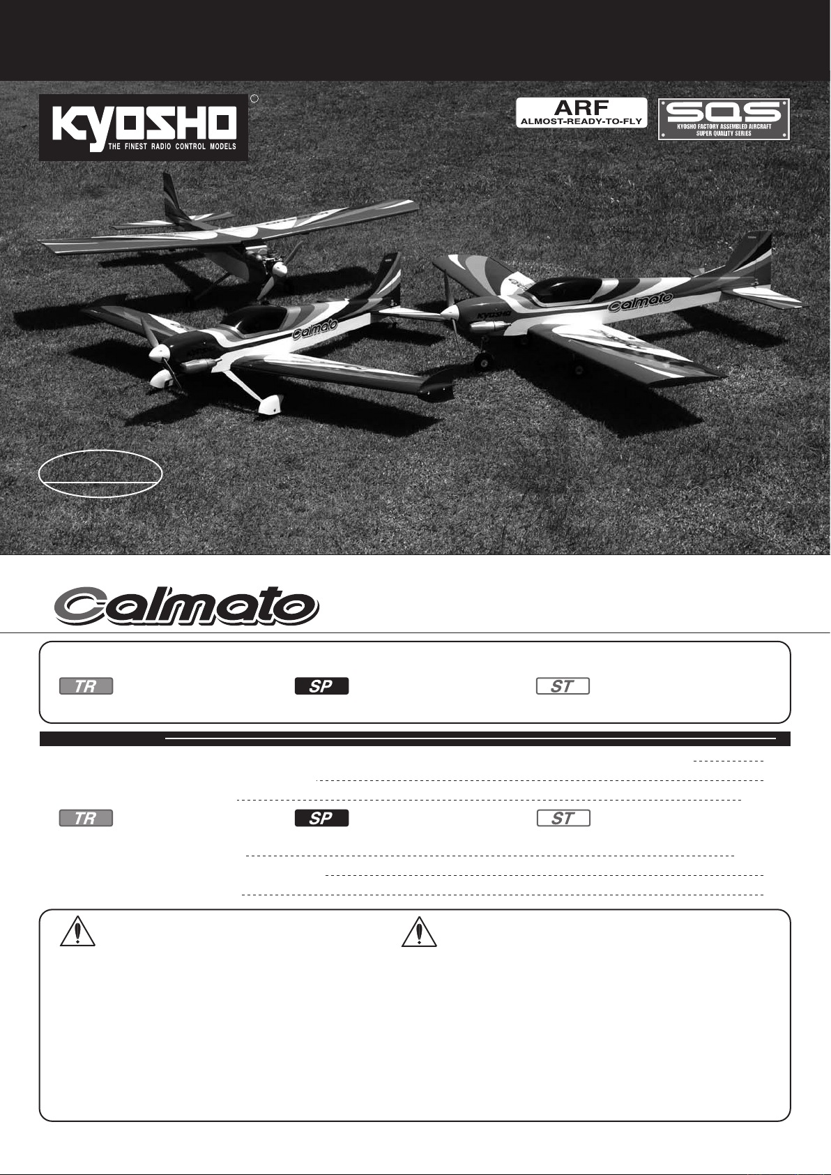
Page 1
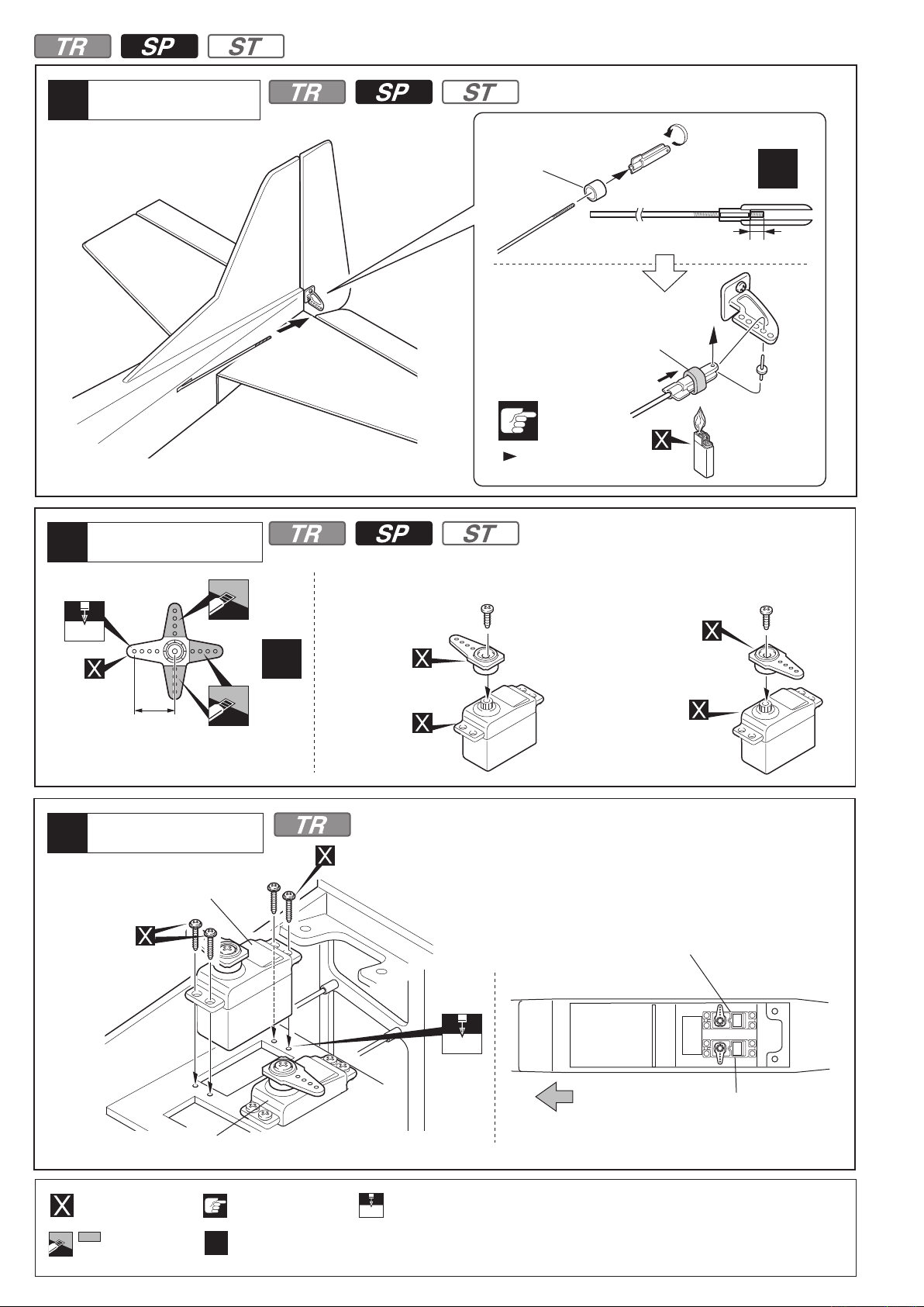
※組立てる前にこの説明書を良くお読みになり十分に理解してください。
Before Begining assembly, please read these instructions thoroughly.
R
For Intermediate
&
Advanced Flyers
中・上級者向
組立/取扱説明書
INSTRUCTION MANUAL
WINGSPAN: 1400mm (55.1") - TR
1400mm (55.1") - SP
1300mm (51.2") - ST
カルマートST/SP/TRGP1400
1 : 7 Scale Radio Controlled Super Quality Series Engine Powered Aircraft
TR / SP / ST
※この取扱説明書は、STモデル・SPORTSモデル・TRAINERモデルの説明をしております。下記のマークに注意してお読みください。
This instruction manual applies to both ST model and SPORTS model, TRAINER model. Refer to the symbols below when using this manual.
No.11051
目 次
●キットの他にそろえる物/組立に必要な工具
●組立て前の注意
●本体の組立て
●分解図
●安全上の注意
●パーツリスト
INDEX
/ EXPLODED VIEW
TRAINERモデルの場合 SPORTSモデルの場合 STモデルの場合
This symbol applies
to STmodel only.
/ BEFORE YOU BEGIN
/ ASSEMBLY
/CAUTIONS FOR SAFETY
/ PARTS LIST
No.11063
This symbol applies
to SPORTS model only.
/ REQUIRED FOR OPERATION / TOOLS REQUIRED
No.11063 No.11051
p16 ~25p4 ~15 p26 ~33
No.11062
No.11062
GP1400
This symbol applies
to TRAINER model only.
2
3
4 ~ 33
34 ~ 36
36
37
安全のための注意事項
この無線操縦模型は玩具ではありません!
●この商品は高い性能を発揮するように設計されています。
組立てに不慣れな方は、模型を良く知っている人にアド
バイスを受け確実に組立ててください。
●小さい部品があるので、組立て作業は、幼児の手がとど
かない所で必ず行ってください。
●飛行して楽しむ場所は万一の事故を考えて、安全を確認
してから責任をもってお楽しみください。
●組立てた後も、説明書がいつでも見られるように大切に
保管してください。
●ラジコン保険に加入して安全に楽しみましょう。
※製品改良のため、予告なく仕様を変更する場合があります。
© Copyright 2010 KYOSHO CORPORATION
11051-T01
/禁無断転載複製
*SPECIFICATIONS ARE SUBJECT TO CHANGE WITHOUT NOTICE.
UNDER SAFETY PRECAUTIONS
This radio control model is not a toy!
●First-time builders should seek the advice of experienced
modellers before beginning assembly and if they do not fully
understand any part of the construction.
●Assemble this kit only in places out of children’s reach!
Take enough safety precautions prior to operating this model.
●
You are responsible for this model’s assembly and safe operation!
●Always keep this instruction manual ready at hand for quick
reference, even after completing the assembly.
●Taking out liability insurance is recommended.
No.11051
No.11063
No.11062
Page 2
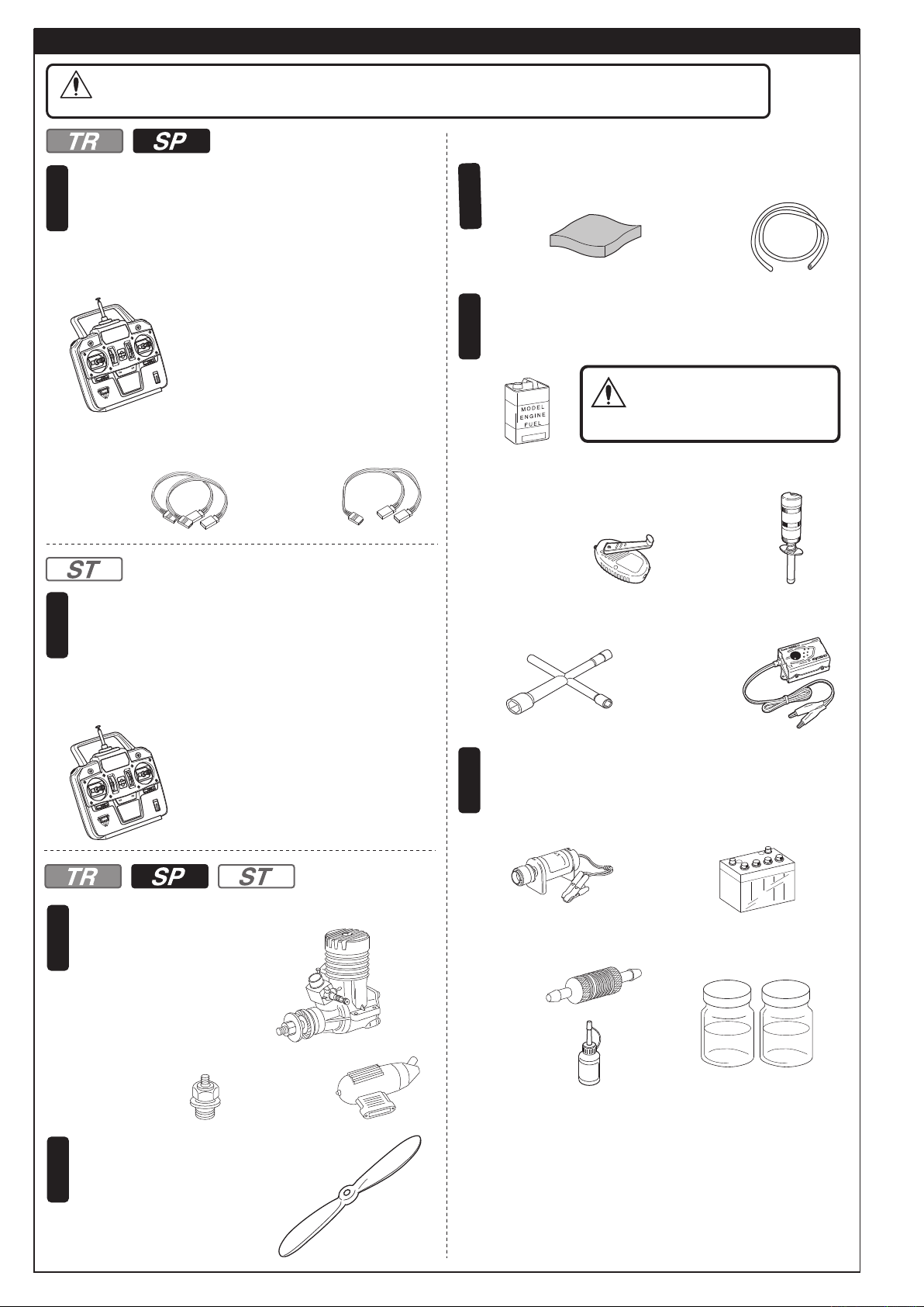
キットの他にそろえる物(別購入品)
下記商品のメーカー、サイズ等は、販売店とご相談ください。
注意
1
■
エルロンサーボ用延長コード…2本
CAUTION: For details concerning the equipment listed below (size, maker, etc.), check with your hobby shop.
*TRAINER, SPORTSモデル
TRAINER, SPORTS model
4チャンネル以上の飛行機用無線操縦機(プロポ)セット
(5標準サーボ)と電池。
This model will requie a minimum 4 channel radio control
(with 5 standerd servo) for aircraft.
■飛行機用4チャンネル以上プロポ
A minimum 4 channel radio control
system for aircraft.
*プロポの取扱い方は、プロポに付属の説明書
を参考にしてください。
For handling the radio properly, refer to its
instruction manual.
■二股コード…1本
Aileron servo extension lead x 2
Y- Harness x 1
REQUIRED FOR OPERATION (Not included in kit!)
■スポンジシート
4
Shock Protecting Foam
燃料、始動用具
Required for engine starting:
5
■グロー燃料
Model Glow Fuel.
警告
■シリコンチューブ
Fuel Tube
ガソリンや灯油は使用禁止
WARNING: Never use petrol/
gasoline with glow
engines.
*STモデル
ST model
4チャンネル以上の飛行機用無線操縦機(プロポ)セット
1
(4標準サーボ)と電池。
This model will requie a minimum 4 channel radio control
(with 4 standerd servo) for aircraft.
■飛行機用4チャンネル以上プロポ
A minimum 4 channel radio control
system for aircraft.
*プロポの取扱い方は、プロポに付属の説明書
を参考にしてください。
For handling the radio properly, refer to its
instruction manual.
エンジン及びマフラー
2
Engine and Muffler
■飛行機用エンジン
Model Aircraft Engine
*2サイクル .25 ~ .36
*2 Stroke .25 ~ .36
■プラグ
Glow Plug
■マフラー
Muffler
■燃料ポンプ
Fuel Pump
No.80703
F-チャージャー
HPポンプII
F-Charger
HP pump II
■プラグレンチ
GlowPlug Wrench
さらに用意すると良いもの
6
Other equipment for enhancing aircraft operation &
■No. 36215 スパーク
ブースター2.0
Spark Booster 2.0
■No. 36217 ブースター
チャージャー2.0
Booster Charger 2.0
performance
■エンジン始動用スターター
Engine Starter
■燃料フィルター ■ウレタン塗料(クリアー)
Fuel Filter Polyurethane paint (Clear)
■瞬間接着剤
Instant Glue
KYOSHO
Special Glue
■スターター用12Vバッテリー
12V Battery (for starter)
+
A B
プロペラ及び
3
Propeller and Spinner
*ご使用になるエンジンに合った
サイズをお買い求めください。
Purchase a propeller that
will match your engine.
2
スピンナー
■プロペラ
Propeller
Page 3
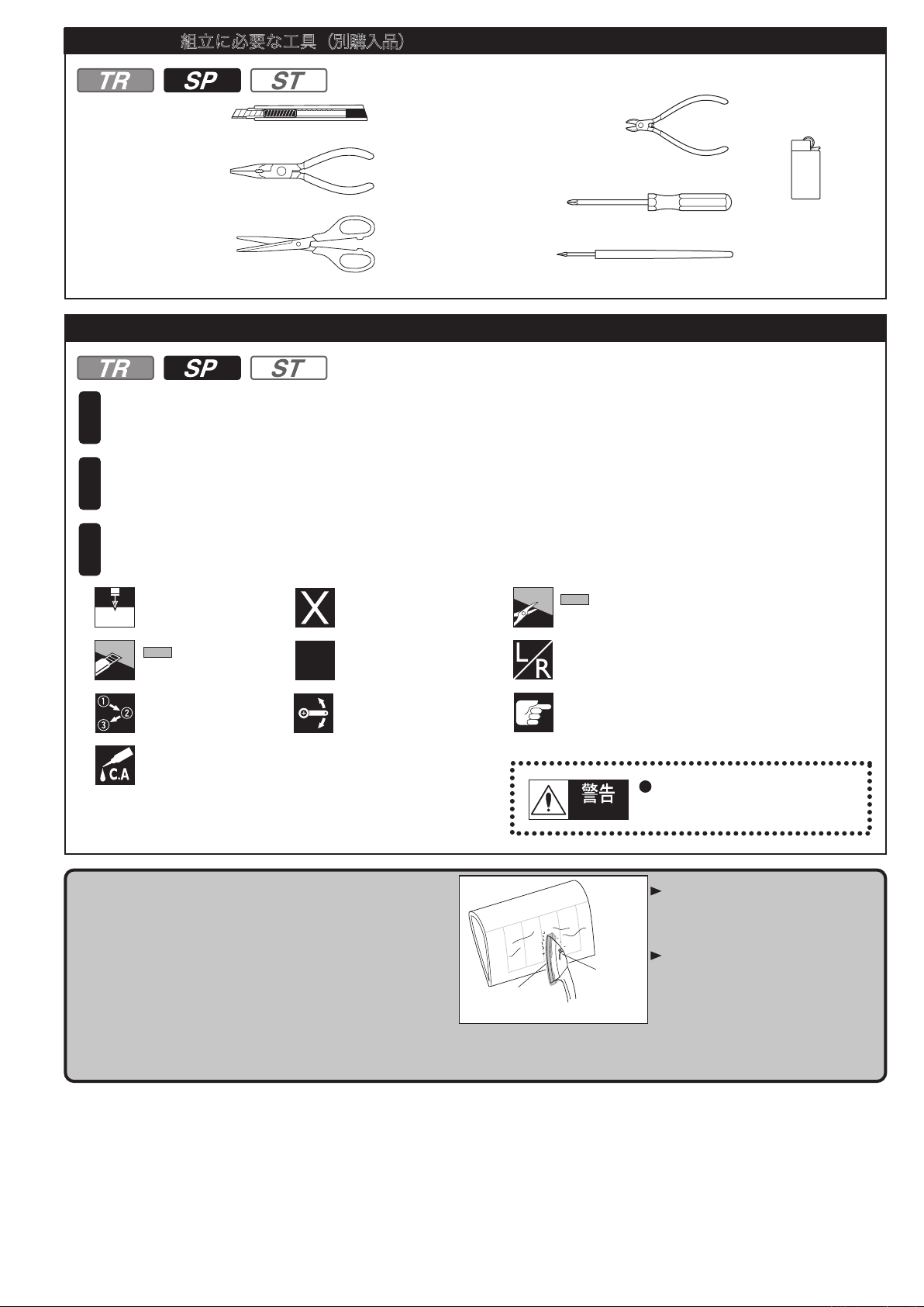
組立に必要な工具(別購入品)
TOOLS REQUIRED (Purchase separately!)
■カッターナイフ
Sharp Hobby Knife
■ラジオペンチ
Needle Nose Pliers
■ハサミ
Scissors
組立て前の注意
■ニッパー
Wire Cutters
■+ドライバー(大、中、小)
Phillips Screwdriver (L, M, S)
■キリ
Awl
BEFORE YOU BEGIN
■ライター
Lighter
組立てる前に説明書を良く読んで、おおよその構造を理解してから組立てに入ってください。
1
Read through the manual before you begin, so you will have an overall idea of what to do.
キットの内容をお確かめください。万一不良、不足がありましたら、お買い求めの販売店にご相談いただくか、
2
当社「ユーザー相談室」までご連絡ください。
Check all parts. If you find any defective or missing parts, contact your local dealer or our Kyosho Distributor.
説明書に使われているマーク
3
Symbols used throughout this instruction manual, comprise:
3mmの穴をあける(例)。
3mm
Drill holes with the
specified diameter.
をカットする。
Cut off shaded portion.
番号の順に組立てる。
Assemble in the
specified order.
瞬間接着剤で接着する。
Apply instant glue
(CA glue, super glue).
完成機に貼ってあるフィルムは、温度や湿度など気候
条件が工場組立の時から変化すると、多少タルミが出
ることがあります。飛行には、さしつかえありませんが、
アイロンをあてると タルミ がとれます。
The pre-covered film on ARF kits may wrinkle due to
variations of temperature. Smooth out as explained
at right.
別購入品。
Must be purchased
separately!
2セット組立てる(例)。
Assemble as many
x2
times as specified.
可動するように組立てる。
Ensure smooth, non-binding
movement when assembling.
あて布
with cover (cloth)
をカットする。
Cut off shaded portion.
左右同じように組立てる。
Assemble left and right
sides the same way.
注意して組立てる所。
Pay close attention here!
重要な注意事項があるマークです。
Warning!
低温
low setting
必ずお読みください。
Do not overlook this symbol!
あて布をしたアイロンを低温であて、
必要に応じて温度を上げてゆく。
温度を上げすぎるとフイルムが溶ける
ので注意する
Use an iron covered with a cloth!
Start at low setting. Increase the
setting if necessary. If it is too high,
you may damage the film.
フィルムのたるみ止めやはがれ止めのために、クリヤーウレタン塗装を行ってください。
You can keep the covering film from wrinkling or peeling by spraying the plane with clear polyurethane.
3
Page 4
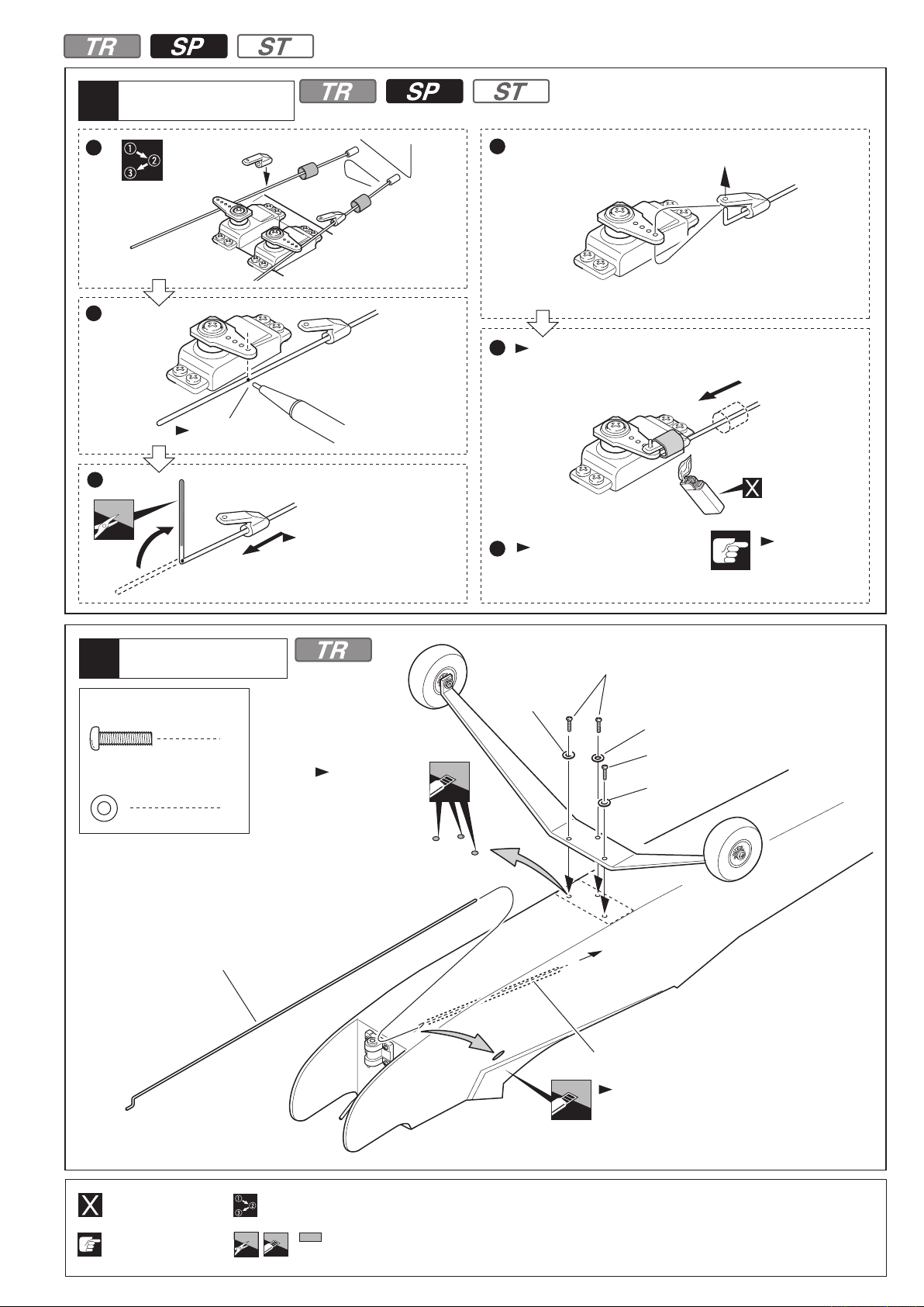
本体の組立
TRAINERバージョン
ASSEMBLY
TRAINER Version
エルロンサーボ
Aileron Servo
1
2mm
約13.5mm
approx. 13.5mm
主翼
2
Main Wing
No.11063
x2
SPORTSモデルの場合は 16ページへ STモデルの場合は 24ページへ
The case of SPORTS model.
<左側>
< Left side >
<右側>
P16
< Right side >
No.11062
The case of ST model.
サーボを取り付ける前に、
必ずサーボのニュートラルを
出しておく必要があります。
Always set the servos
P24
at their neutral position
サーボ付属。
Supplied with
the servo.
サーボ付属。
Supplied with
the servo.
<左側>
フィルムのみ。
Only cut the film.
before installing the servos.
90
< Left side >
<右側>
< Right side >
<左側主翼下面>
< Bottom view of left wing >
主翼
3
Main Wing
サーボ付属。
Supplied with
the servo.
1.5mm
サーボ付属。
Supplied with
the servo.
1.5mm
<左側主翼下面>
< Bottom view of
left wing >
1
糸を結ぶ。
2
Tie the string.
サーボ延長コード
Servo extension
cords
フィルムのみ。
Only cut the film.
3
糸とサーボコードを引き出す。
Pull out servo cord with string.
<主翼下面>
< Bottom view >
1.5
mm
4
をカットする。
Cut off shaded portion.
1.5mmの穴をあける(例)。
Drill holes with the specified
diameter.
番号の順に組立てる。
Assemble in the
specified order.
左右同じように組立てる。
Assemble left and right sides
the same way.
別購入品。
Must be purchased
separately!
注意して組立てる所。
Pay close attention
here!
Page 5
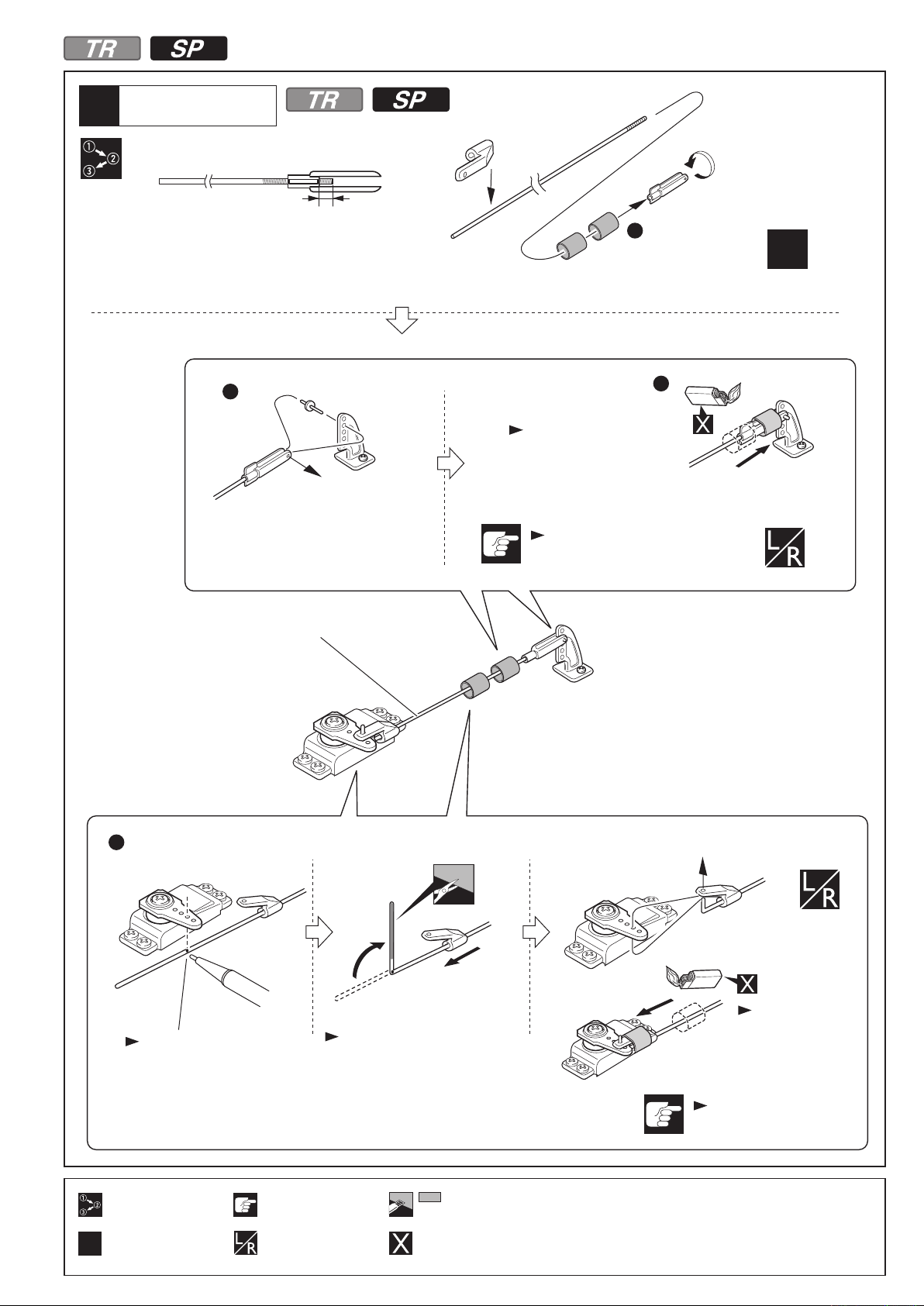
エルロンロッド
Aileron Rod
4
約3mm
approx. 3mm
1
x2
2
3
ヒシチューブに熱
を加えて収縮させ
る。
Apply heat to
shrink the tube.
火傷に注意。
Beware of the flame!
エルロンロッド
Aileron Rod
4
番号の順に組立てる。
Assemble in the
specified order.
2セット組立てる(例)。
Assemble as many times
x2
as specified.
マジックペンで印をつける。
Mark the spot to attach.
注意して組立てる所。
Pay close attention
here!
左右同じように組立てる。
Assemble left and right sides
the same way.
ペンチ等で曲げた後、
余分な部分を切り取ります。
Bend it with pliers,cut extra part.
をカットする。
Cut off shaded portion.
別購入品。
Must be purchased
separately!
ヒシチューブに熱
を加えて収縮させ
る。
Apply heat to
shrink the tube.
火傷に注意。
Beware of the flame!
5
Page 6
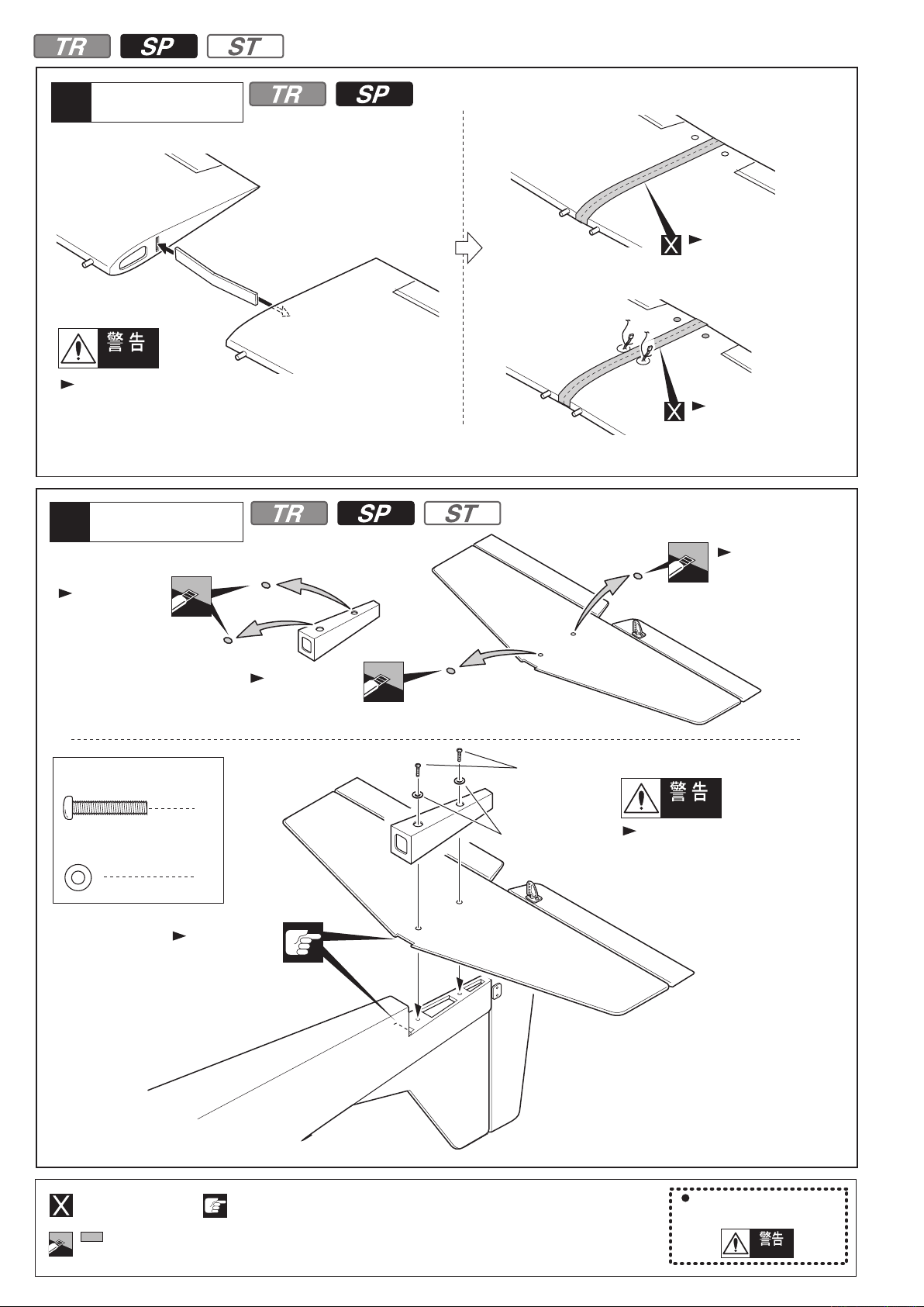
主翼
5
Main Wing
<主翼上面>
< Top view. >
Warning!
確実に止める。飛行中にはずれると操縦不能になり
事故につながります。
Securely glue together. If it comes off during flights, you may
lose control of your airplane, resulting in an accident !
尾翼
6
Tail Wing
<主翼上面>
< Top view. >
セロテープ等で止める
Tape
<主翼下面>
< Bottom view >
セロテープ等で止める
Tape
フィルムのみ。
Only cut the film.
フィルムのみ。
Only cut the film.
3 x 16mm
3mm
ビス
Screw
ワッシャー
Washer
フィルムのみ。
2
2
みぞにはめる。
Fit into the gap.
Only cut the film.
3x16mm
3mm
Warning!
確実に取付ける。
飛行中にはずれると操縦不能になり
事故につながります。
Tighten the screws securely.
If it comes off during flights, you may
lose control of your airplane, resulting
in an accident !
6
別購入品。
Must be purchased
separately!
をカットする。
Cut off shaded portion.
注意して組立てる所。
Pay close attention
here!
重要な注意事項があるマークです。
必ずお読みください。
Do not overlook this symbol!
Warning!
Page 7
エレベーター/ラダーロッド
7
Elevator / Rudder Rod
エレベーター/ラダーロッド
8
Elevator / Rudder Rod
エレベーターロッド
Elevator Rod
9
<エレベーターロッド>
< Elevator Rod >
フィルムのみ。
Only cut the film.
フィルムのみ。
Only cut the film.
収縮チューブ
Heat-shrink Tube
x2
別購入品。
Must be purchased
separately!
をカットする。
Cut off shaded portion.
注意して組立てる所。
Pay close attention
here!
2セット組立てる(例)。
Assemble as many times
x2
as specified.
約3mm
approx. 3mm
<エレベーターロッド>
< Elevator Rod >
収縮チューブ
Heat-shrink Tube
火傷に注意。
Beware of the flame!
7
Page 8
エレベーターロッド
Elevator Rod
10
<ラダーロッド>
< Rudder Rod >
サーボ
Servo
11
<エレベーターサーボ>
< Elevator Servo >
収縮チューブ
Heat-shrink Tube
<ラダーロッド>
< Rudder Rod >
収縮チューブ
Heat-shrink Tube
火傷に注意。
Beware of the flame!
<ラダーサーボ>
< Rudder Servo >
x2
約3mm
approx. 3mm
2mm
サーボ
Servo
12
サーボ付属。
Supplied with
the servo.
約16mm
approx. 16mm
<ラダーサーボ>
< Rudder Servo >
x2
サーボ付属。
Supplied with
the servo.
サーボ付属。
Supplied with
the servo.
サーボ付属。
Supplied with
the servo.
サーボ付属。
Supplied with
the servo.
サーボ付属。
Supplied with
the servo.
<ラダーサーボ>
< Rudder Servo >
1.5mm
8
<エレベーターサーボ>
< Elevator Servo >
別購入品。
Must be purchased
separately!
をカットする。
Cut off shaded portion.
注意して組立てる所。
Pay close attention
here!
2セット組立てる(例)。
Assemble as many times
x2
as specified.
1.5mmの穴をあける(例)。
Drill holes with the specified
diameter.
1.5
mm
前
Front
<エレベーターサーボ>
< Elevator Servo >
Page 9
13
サーボ
Servo
1
4
2
ヒシチューブに熱を加えて収縮させる。
5
Apply heat to shrink the tube.
印をつける。
Mark the spot to attach.
3
ペンチ等で曲げた後、余分
な部分を切り取ります。
Bend it with pliers,cut extra
part.
エレベーターサーボ側も
6
同様に取付けます。
Install the elevator servo
in the same way.
火傷に注意。
Beware of the
flame!
14
3 x 12mm
3mm
メインギヤ
Main Gear
ビス
Screw
ワッシャー
Washer
3
3
ノーズギヤロッド
Nose Gear Rod
フィルムのみ。
Only cut the film.
3x12mm
3mm
3mm
3x12mm
3mm
PPパイプ
PP Pipe
フィルムのみ。
Only cut the film.
別購入品。
Must be purchased
separately!
注意して組立てる所。
Pay close attention
here!
番号の順に組立てる。
Assemble in the
specified order.
をカットする。
Cut off shaded portion.
9
Page 10
15
ノーズギヤ
Nose Gear
3x3mm
3 x 3mm
2mm
1.5mm
3x3mm
セットビス
Set Screw
ワッシャー
Washer
Eリング
E ring
3
1
1
3x3mm
ノーズギヤロッド
Nose Gear Rod
2mm
Eリング
E ring
ノーズギヤロッド
Nose Gear Rod
2mm
ペンチ等で曲げる。
Bend it with pliers.
3x3mm
エンジンマウント
16
Engine Mount
3 x 16mm
3mm
ワッシャー
Washer
3x3mm
ペンチ等で曲げる。
Bend it with pliers.
ビス
Screw
4
3mm
4
3x16mm
10
1.5
mm
可動するように組立てる。
Ensure smooth non-binding
movement while assembling.
1.5mmの穴をあける(例)。
Drill holes with the specified
diameter.
3x16mm
3mm
Page 11
エンジンマウント
17
Engine Mount
3 x 25mm
Cap Screw
キャップビス
エンジン
Engine
横から見た図
Side View
113mm
3mm
ナイロンナット
Nylon Nut
3mm
ワッシャー
Washer
エンジンに合わせ3.2mmの穴を開ける。
1
Align to engine and make 3.2mm holes.
4
4
4
3.2
mm
エンコンロッド
Throttle Rod
3.2
mm
3x25mm
上図の寸法に合わせる。
Align to same dimensions as shown above.
上側のパイプは、
2
マフラーへ。
To Muffler.
2
下側のパイプは、
キャブレターへ。
To Carburetor.
番号の順に組立てる。
Assemble in the
specified order.
3mmの穴をあける(例)。
Drill holes with the
3mm
specified diameter.
エンコンロッドを入れる
3
Throttle Rod into the hole.
4
エンジンの取扱説明書にしたがって、
配管を行ってください。
Refer to engine's instruction manual
and set up piping.
別購入品。
Must be purchased
separately!
左右同じように組立てる。
Assemble left and right
sides the same way.
3mm
3mm
3x25mm
エンジンマウント
Engine Mount
3mm
3mm
11
Page 12
サーボ
18
Servo
<スロットルサーボ>
< Throttle Servo >
サーボ付属。
Supplied with
the servo.
サーボ付属。
Supplied with
the servo.
2mm
約16mm
approx. 16mm
サーボ付属。
Supplied with
the servo.
リンケージ
19
Linkage
3 x 3mm
リンケージストッパー
Linkage Stopper
セットビス
Set Screw
<スロットルサーボ>
< Throttle Servo >
ノーズギヤロッド
Nose Gear Rod
1.5mm
スロットルロッド
Throttle Rod
スロットルロッド
Throttle Rod
1
1
ペンチ等で曲げる。
Bend it with pliers.
1.5mm
ワッシャー
2mm
Washer
Eリング
1.5mm
E ring
ペンチ等で曲げる。
Bend it with pliers.
1
1
スロットルロッド
Throttle Rod
前
Front
2mm
2mm
ノーズギヤロッド
Nose Gear Rod
3 x 3mm
スロットルサーボ
Throttle Servo
Eリング
E ring
3mm
12
をカットする。
Cut off shaded portion.
3mmの穴をあける(例)。
Drill holes with the
specified diameter.
別購入品。
Must be purchased
separately!
可動するように組立てる。
Ensure smooth, non-binding
movement when assembling.
Page 13

20
プロペラ
Propeller
3 x 12mm
21
TPビス
TP Screw
スイッチ
Switch
3x12mm
2
Warning!
エンジン回転中にプロペラがはずれないように、
確実にナットをしめる。
回転中にはずれるとケガのおそれがあります。
Securely tighten the nut holding the propeller
for it not come off when the engine is spinning.
If coming off, there is a high risk of injury!
スイッチ
Switch
スイッチに
付属のプレート
Included with
the switch.
受信機、バッテリー
22
Receiver,Battery
マジックテープ
Velcro
重心位置(P14 参照)に合わせて
置く位置を調整してください。
In order to obtain the CG (refer to P14 )
specified, adjust the position of the battery.
受信機
Receiver
バッテリー
Battery
24
24
穴をあける
Drill holes.
スイッチに付属のビス
Included with the switch.
スポンジ
Foam Pad
テープ等で止める。
Bind with adhesive tape.
確実に取り付ける。飛行中にはずれると
操縦不可能になり事故につながります。
Make certain parts are fixed accurately
and play is reduced to a minimum.
If they come loose in flighe accidents
may result.
注意して組立てる所。
Pay close attention here!
をカットする。
Cut off shaded portion.
別購入品。
Must be purchased
separately!
重要な注意事項があるマークです。
必ずお読みください。
Do not overlook this symbol!
Warning!
13
Page 14

23
4mm
主翼
Main Wing
ワッシャー
Washer
A = A’
4mm
2
エルロンサーボのコネクターを
接続する。
Connect the aileron servo.
Warning!
確実に取り付ける。
飛行中にはずれると操縦不能
になり事故につながります。
Tighten screws securely. If it
comes off during flights,
you may lose control of
your airplane,
resulting in an accident !
二股コード
Y- Harness
4mm
アンテナを張る
Antenna
2mm
A
A’
受信機
Receiver
セロテープ等で
留める
Tape
24
注意して組立てる所。
Pay close attention
here!
別購入品。
Must be purchased
separately!
受信機
Receiver
重心位置
C of G position
図の位置に重心が来るように、受信機等
を前後に移動し、重心位置を合わせる。
In order to obtain the CG specified, reposition
the receiver and other equipment.
受信機等の移動でも重心位置が
合わない場合は、
重りを載せて合わせる。
If not obtain the CG specified,
add a weight and adjust.
1.5mmの穴をあける(例)。
Drill holes with the specified
diameter.
1.5
mm
Warning!
約
82~87mm
approx.
重心のチェックをする前に飛行は、おこなわない。
重心位置が正しくないと操縦不能になり事故につながります。
Do not fly before confirming the correct location of the CG.
If the CG is incorrect, you lose control of your airplane which leads
to accidents!
82~87mm
重心位置
CG
重要な注意事項があるマークです。
必ずお読みください。
Do not overlook this symbol!
Warning!
14
Page 15

図の様に各舵が動くように調整する。図の動作量は通常の飛行に適した舵角です。
Adjust the travel of each control surface to the values in the diagrams.
25
舵角調整
Adjustment
<エルロン> <エレベーター> <ラダー>
< Aileron > < Elevator > < Rudder >
舵角
Angle
舵角
Angle
26
測定位置
Position for
left diagram.
デカール
Decals
6mm
6mm
舵角
Angle
測定位置
Position for
left diagram.
測定位置
Position for
left diagram.
7mm
7mm
25mm 25mm
付属のデカールはパッケージ を
参考に貼ってください。
Apply included decals.
For the correct placement of decals,
please refer to box top.
注意して組立てる所。
Pay close attention
here!
重要な注意事項があるマークです。
必ずお読みください。
Do not overlook this symbol!
Warning!
15
Page 16

STモデルの場合は 24ページへ
No.11062
The case of ST model.
エルロンサーボ
Aileron Servo
27
1
P4 の工程手順で、組立ててください。
Assemble in this order.
本体の組立
SPORTSバージョン
ASSEMBLY
SPORTS Version
P24
主翼
28
Main Wing
フィルムのみ。
Only cut the film.
主翼
29
Main Wing
サーボ付属。
Supplied with
the servo.
サーボ付属。
Supplied with
the servo.
フィルムのみ。
Only cut the film.
<左側主翼下面>
< Bottom view of
left wing >
<左側主翼下面>
< Bottom view of
left wing >
フィルムのみ。
Only cut the film.
<左側主翼上面>
< Top view of left wing >
<主翼上面>
< Top view >
1.5mm
1.5mm
エルロンサーボ/主翼
Aileron Servo / Main Wing
30
4 5
P5 P6〜 の工程手順で、組立ててください。
Assemble in this order.
をカットする。
Cut off shaded portion.
左右同じように組立てる。
Assemble left and right sides
the same way.
1.5mmの穴をあける(例)。
Drill holes with the specified
diameter.
1.5
mm
番号の順に組立てる。
Assemble in the
specified order.
1
糸を結ぶ。
2
Tie the string.
別購入品。
Must be purchased
separately!
サーボ延長コード
Servo extension
cords
糸とサーボコードを引き出す。
Pull out servo cord with string.
16
Page 17

31
3 x 12mm
メインギヤ
Main Gear
TPビス
TP Screw
3x12mm
3x12mm
8
尾翼/ラダーロッド/エレベーターロッド
32
Tail Wing / Rudder Rod / Elevator Rod
P6 〜 P7 の工程手順で、組立ててください。
6
Assemble in this order.
エレベーター/ラダーロッド
33
Elevator / Rudder Rod
7
2mm
2mm
エレベーター/ラダーロッド/サーボ
34
Elevator / Rudder Rod / Servo
P7 〜 P8 の工程手順で、組立ててください。
9 11
Assemble in this order.
左右同じように組立てる。
Assemble left and right sides
the same way.
1.5mmの穴をあける(例)。
Drill holes with the specified
1.5
mm
diameter.
17
Page 18

サーボ
35
Servo
11
P8 の工程手順で、組立ててください。
Assemble in this order.
サーボ
36
Servo
フィルムのみ。
Only cut the film.
前
Front
<エレベーターサーボ>
< Elevator Servo >
サーボ付属。
Supplied with
the servo.
1.5mm
サーボ付属。
Supplied with
the servo.
1.5mm
<ラダーサーボ>
< Rudder Servo >
サーボ
37
Servo
13
P9
の工程手順で、組立ててください。
Assemble in this order.
ノーズギヤ
38
Nose Gear
PPパイプ
PP Pipe
フィルムのみ。
Only cut the film.
3mm
18
別購入品。
Must be purchased
separately!
3mmの穴をあける(例)。
Drill holes with the
specified diameter.
をカットする。
Cut off shaded portion.
Page 19

39
ノーズギヤ
Nose Gear
3x3mm
3 x 3mm
2mm
1.5mm
3x3mm
セットビス
Set Screw
ワッシャー
Washer
Eリング
E ring
3
1
1
3x3mm
ペンチ等で曲げる。
Bend it with pliers.
2mm
2mm
Eリング
E ring
3x3mm
エンジンマウント
40
Engine Mount
3 x 16mm
3mm
ワッシャー
Washer
3x3mm
ペンチ等で曲げる。
Bend it with pliers.
ビス
Screw
4
3mm
4
3x16mm
1.5mmの穴をあける(例)。
Drill holes with the specified
diameter.
1.5
mm
可動するように組立てる。
Ensure smooth non-binding
movement while assembling.
3x16mm
注意して組立てる所。
Pay close attention here!
3mm
SPORTSモデル
の場合はノーズギヤを装着。
Install nose gear for SPORTS
models.
19
Page 20

エンジンマウント
41
Engine Mount
横から見た図
Side View
3 x 25mm
Cap Screw
3mm
Nylon Nut
3mm
Washer
キャップビス
ナイロンナット
ワッシャー
4
4
4
エンジン
Engine
3mm
3mm
3.2
mm
3.2
mm
エンジンに合わせ3.2mmの穴を開ける。
1
Align to engine and make 3.2mm holes.
3mm
3mm
113mm
上図の寸法に合わせる。
Align to same dimensions as shown above.
上側のパイプは、
2
マフラーへ。
To Muffler.
3mm
3mm
エンジンマウント
Engine Mount
3x25mm
エンジンの取扱説明書にしたがって、
配管を行ってください。
Refer to engine's instruction manual
and set up piping.
5
3x25mm
3x25mm
2
下側のパイプは、
キャブレターへ。
To Carburetor.
4
エンコンロッド
Throttle Rod
エンコンロッドを入れる
3
Throttle Rod into the hole.
3mm
20
番号の順に組立てる。
Assemble in the
specified order.
3mmの穴をあける(例)。
Drill holes with the
specified diameter.
別購入品。
Must be purchased
separately!
左右同じように組立てる。
Assemble left and right
sides the same way.
Page 21

サーボ
42
Servo
<スロットルサーボ>
< Throttle Servo >
2mm
約16mm
approx. 16mm
サーボ付属。
Supplied with
the servo.
43
サーボ
Servo
フィルムのみ。
Only cut the film.
前
Front
サーボ付属。
Supplied with
the servo.
<スロットルサーボ>
< Throttle Servo >
1.5mm
スロットルロッド
Throttle Rod
1.5mm
サーボ付属。
Supplied with
the servo.
SPORTSモデルの場合は
ノーズギヤロッドを装着。
Install nose gear rod for
SPORTS models.
リンケージ
44
Linkage
3 x 3mm
リンケージストッパー
Linkage Stopper
2mm
1.5mm
3mm
セットビス
Set Screw
ワッシャー
Washer
Eリング
E ring
別購入品。
Must be purchased
separately!
3mmの穴をあける(例)。
Drill holes with the
specified diameter.
1
1
1
1
可動するように組立てる。
Ensure smooth, non-binding
movement when assembling.
をカットする。
Cut off shaded portion.
スロットルロッド
Throttle Rod
2mm
2mm
3 x 3mm
Eリング
E ring
スロットルサーボ
Throttle Servo
21
Page 22

45
カウリング
Cowling
2 x 8mm
TP Screw
TPビス
カウリング
Cowling
プロペラ
46
Propeller
3 x 12mm
TPビス
TP Screw
4
2
2mm
約1~2mm
approx . 1~2mm
1.5mm
使用するエンジンに合わせて
カウリングをカットする。
Trim the cowling so it will
match your engine.
2 x 8mm
47
2 x 8mm
3x12mm
キャノピー
Canopy
TPビス
TP Screw
Warning!
エンジン回転中にプロペラがはずれないように、
確実にナットをしめる。
回転中にはずれるとケガのおそれがあります。
Securely tighten the nut holding the propeller
for it not come off when the engine is spinning.
If coming off, there is a high risk of injury!
4
2mm
1.5mm
2x8mm
2mm
3mm
22
注意して組立てる所。
Pay close attention here!
3mmの穴をあける(例)。
Drill holes with the
specified diameter.
1.5mm
左右同じように組立てる。
Assemble left and right
sides the same way.
別購入品。
Must be purchased
separately!
重要な注意事項があるマークです。
必ずお読みください。
Do not overlook this symbol!
Warning!
Page 23

48
スイッチ
Switch
スイッチに
付属のプレート
Included with
the switch.
スイッチ
Switch
穴をあける
Drill holes.
スイッチに付属のビス
Included with the switch.
受信機、バッテリー
49
Receiver,Battery
受信機
Receiver
バッテリー
Battery
マジックテープ
Velcro
確実に取り付ける。飛行中にはずれると
操縦不可能になり事故につながります。
Make certain parts are fixed accurately
and play is reduced to a minimum.
If they come loose in flighe accidents
may result.
スポンジ
Foam Pad
テープ等で止める。
Bind with adhesive tape.
重心位置(P24 参照)に合わせて
置く位置を調整してください。
In order to obtain the CG (refer to P24 )
specified, adjust the position of the battery.
51
51
セロテープ等で
留める
Tape
1.5mmの穴をあける(例)。
Drill holes with the specified
diameter.
1.5
mm
注意して組立てる所。
Pay close attention
here!
2mm
スポンジ
Foam Pad
別購入品。
Must be purchased
separately!
をカットする。
Cut off shaded portion.
受信機
Receiver
アンテナを張る
Antenna
重要な注意事項があるマークです。
必ずお読みください。
Do not overlook this symbol!
Warning!
23
Page 24

主翼
50
Main Wing
4mm
ワッシャー
Washer
エルロンサーボのコネクターを
接続する。
Connect the aileron servo.
4mm
2
4mm
重心位置
C of G position
51
フィルムのみ。
Only cut the film.
図の位置に重心が来るように、受信機等
を前後に移動し、重心位置を合わせる。
In order to obtain the CG specified, reposition
the receiver and other equipment.
受信機等の移動でも重心位置が
合わない場合は、
重りを載せて合わせる。
If not obtain the CG specified,
add a weight and adjust.
二股コード
Y- Harness
Warning!
A = A’
A
Warning!
確実に取り付ける。
飛行中にはずれると操縦不能になり
事故につながります。
Tighten screws securely. If it comes off
during flights, you may lose control of
your airplane, resulting in an accident !
重心のチェックをする前に飛行は、おこなわない。
重心位置が正しくないと操縦不能になり事故につながります。
Do not fly before confirming the correct location of the CG.
If the CG is incorrect, you lose control of your airplane which
leads to accidents!
重心位置
CG
A’
24
注意して組立てる所。
Pay close attention
here!
をカットする。
Cut off shaded portion.
別購入品。
Must be purchased
separately!
約
82~87mm
approx.
82~87mm
重要な注意事項があるマークです。
必ずお読みください。
Do not overlook this symbol!
Warning!
Page 25

図の様に各舵が動くように調整する。図の動作量は通常の飛行に適した舵角です。
Adjust the travel of each control surface to the values in the diagrams.
52
舵角調整
Adjustment
<エルロン> <エレベーター> <ラダー>
< Aileron > < Elevator > < Rudder >
舵角
Angle
舵角
Angle
53
測定位置
Position for
left diagram.
デカール
Decals
6mm
6mm
舵角
Angle
測定位置
Position for
left diagram.
7mm
7mm
付属のデカールはパッケージを参考に貼ってください。
Apply included decals. For the correct placement of decals,
please refer to box top.
測定位置
Position for
left diagram.
25mm 25mm
注意して組立てる所。
Pay close attention
here!
25
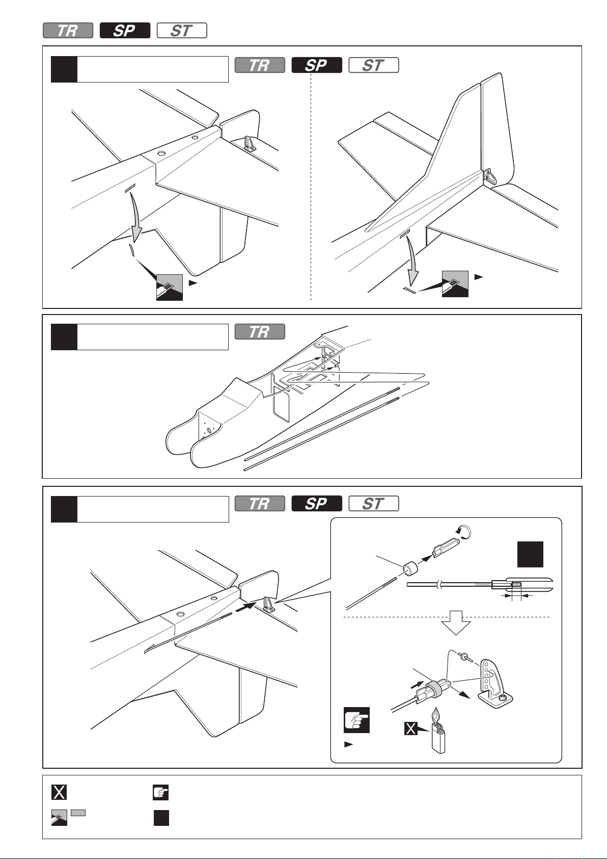
Page 26

本体の組立
STバージョン
ASSEMBLY
ST Version
54
55
主翼
Main Wing
主翼
Main Wing
Warning!
確実に止める。
飛行中にはずれると操縦不能になり事故につながります。
Securely tape together. If it comes off during flights, you may
lose control of your airplane, resulting in an accident !
フィルムのみ。
Only cut the film.
Do not cut into the wood.
<主翼上面>
< Top view >
フィルムのみ。
Only cut the film.
Do not cut into the wood.
<主翼上面>
< Top view. >
エルロンサーボ
56
Aileron Servo
Cut off shaded portion.
別購入品。
Must be purchased
separately!
2mm 2mm
約13.5mm
approx. 13.5mm
約13.5mm
approx. 13.5mm
をカットする。
注意して組立てる所。
Pay close attention
here!
1.5mmの穴をあける(例)。
Drill holes with the specified
diameter.
1.5
mm
セロテープ等で止める。 セロテープ等で止める。
Tape Tape
サーボ付属。
Supplied with
the servo.
<主翼下面>
< Bottom view >
90
サーボを取付ける前に、
必ずサーボのニュートラルを
出しておく必要があります。
Always set the servos
at their neutral position
before installing the servos.
重要な注意事項があるマークです。
必ずお読みください。
Do not overlook this symbol!
Warning!
26
Page 27

エルロンサーボ
Aileron Servo
57
サーボコードを前のすき間から出す。
Take out Servo Lead.
エルロンロッド
Aileron Rod
58
サーボ付属。
Supplied with
the servo.
1.5mm
サーボ付属。
Supplied with
the servo.
<主翼上面>
< Top view. >
1.5mm
4
エルロンロッド
Aileron Rod
約3mm
approx. 3mm
火傷に注意。
Beware of the flame!
1
2 3
x2
x2
ヒシチューブに熱を
加えて収縮させる。
Apply heat to
shrink the tube.
x2
印をつける。
Mark the spot to attach.
2セット組立てる(例)。
Assemble as many times as
specified (here: twice).
番号の順に組立てる。
Assemble in the
specified order.
別購入品。
Must be purchased
separately!
をカットする。
Cut off shaded portion.
ペンチ等で曲げた後、
余分な部分を切取ります。
Bend it with pliers,cut extra part.
注意して組立てる所。
Pay close attention here!
ヒシチューブに熱を
加えて収縮させる。
Apply heat to
shrink the tube.
27
Page 28

59
主翼
Main Wing
3 x 16mm
3mm
60
ビス
Screw
4
ワッシャー
Washer
4
向きに注意。
Note the direction.
フィルムのみ。
Only cut the film.
尾翼/エレベーターロッド/ラダーロッド
Tail Wing / Elevator Rod / Rudder Rod
フィルムのみ。
Only cut the film.
3mm
3 x 16mm
6 7
P6 P7〜 の工程手順で、組立ててください。
Assemble in this order.
エレベーター/ラダーロッド
61
Elevator / Rudder Rod
エレベーターロッド/ラダーロッド
62
Elevator Rod / Rudder Rod
9 10
P7 P8〜 の工程手順で、組立ててください。
Assemble in this order.
をカットする。
Cut off shaded portion.
注意して組立てる所。
Pay close attention
here!
Assemble left and right sides
the same way.
28
Page 29

63
サーボ
Servo
11 36
P8 P18 の工程手順で、組立ててください。
P9
13
Assemble in this order.
メインギヤ
64
Main Gear
3 x 12mm
3mm
ビス
Screw
ワッシャー
Washer
3
3
フィルムのみ。
Only cut the film.
3mm
3x12mm
3mm
3x12mm
3mm
テールギヤ
65
Tail Gear
3 x 12mm
3mm
3mm
Nut
66
ビス
Screw
2
ワッシャー
Washer
4
ナット
2
エンジンマウント
Engine Mount
40 41
P19 P20〜 の工程手順で、組立ててください。
Assemble in this order.
5mm
3mm
3mm
3x12mm
3mm
フィルムのみ。
Only cut the film.
をカットする。
Cut off shaded portion.
29
Page 30

サーボ/リンケージ
67
Servo / Linkage
42 44
P21
〜
Assemble in this order.
カウリング/プロペラ
68
Cowling / Propeller
45 46
P22 〜
Assemble in this order.
キャノピー
69
Canopy
2 x 8mm
TPビス
TP Screw
の工程手順で、組立ててください。
の工程手順で、組立ててください。
4
2mm
70
スイッチ
Switch
スイッチに
付属のプレート
Included with
the switch.
1.5mm
2x8mm
2mm
1.5mm
スイッチ
Switch
穴をあける
Drill holes.
30
1.5
mm
1.5mmの穴をあける(例)。
Drill holes with the specified
diameter.
左右同じように組立てる。
Assemble left and right sides
the same way.
別購入品。
Must be purchased
separately!
をカットする。
Cut off shaded portion.
スイッチに付属のビス
Included with the switch.
Page 31

受信機、バッテリー
71
Receiver,Battery
マジックテープ
Velcro
重心位置(P32 参照)に合わせて
置く位置を調整してください。
In order to obtain the CG (refer to P32 )
specified, adjust the position of the battery.
主翼
72
Propeller
4mm
ワッシャー
Washer
受信機
Receiver
バッテリー
Battery
73
2
73
フィルムのみ。
Only cut the film.
スポンジ
Foam Pad
テープ等で止める。
Bind with adhesive tape.
4mm
確実に取り付ける。飛行中にはずれると
操縦不可能になり事故につながります。
Make certain parts are fixed accurately
and play is reduced to a minimum.
If they come loose in flighe accidents
may result.
Warning!
確実に取付ける。
飛行中にはずれると操縦不能になり
事故につながります。
Tighten screws securely. If it comes off
during flights, you may lose control of
your airplane, resulting in an accident !
4mm
A = A’
エルロンサーボのコネクターを
接続する。
Connect the aileron servo.
フィルムのみ。
Only cut the film.
注意して組立てる所。
Pay close attention here!
3mmの穴をあける(例)。
Drill holes with the
3mm
specified diameter.
別購入品。
Must be purchased
separately!
をカットする。
Cut off shaded portion.
アンテナを張る
Antenna
2mm
A
セロテープ等で
留める
Tape
重要な注意事項があるマークです。
必ずお読みください。
Do not overlook this symbol!
Warning!
A’
31
Page 32

73
重心位置
C of G position
図の位置に重心が来るように、受信機等
を前後に移動し、重心位置を合わせる。
In order to obtain the CG specified, reposition
the receiver and other equipment.
受信機等の移動でも重心位置が
合わない場合は、
重りを載せて合わせる。
If not obtain the CG specified,
add a weight and adjust.
Warning!
約91~96mm
approx. 91~96mm
重心のチェックをする前に飛行は、おこなわない。
重心位置が正しくないと操縦不能になり事故につながります。
Do not fly before confirming the correct location of the CG.
If the CG is incorrect, you lose control of your airplane which leads
to accidents!
重心位置
CG
図の様に各舵が動くように調整する。図の動作量は通常の飛行に
適した舵角です。
Adjust the travel of each control surface to the values in the diagrams.
74
舵角調整
Adjustment
<エルロン> <エレベーター> <ラダー>
< Aileron > < Elevator > < Rudder >
舵角
Angle
75
測定位置
Position for
left diagram.
舵角
Angle
7mm
7mm
デカール
Decals
測定位置
Position for
left diagram.
10mm
10mm
付属のデカールはパッケージ を
参考に貼ってください。
Apply included decals.
For the correct placement of decals,
please refer to box top.
測定位置
Position for
left diagram.
舵角
Angle
30mm 30mm
32
注意して組立てる所。
Pay close attention here!
重要な注意事項があるマークです。
必ずお読みください。
Do not overlook this symbol!
Warning!
Page 33

76
オプションパーツの組立
カナライザー
Canalizer
ASSEMBLY OF OPTIONAL PARTS (Not included in kit!)
STバージョン
ST Version
フィルムのみ。
Only cut the film.
機体中央に。
Align to the center.
フィルムのみ。
Only cut the film.
フィルムのみ。
Only cut the film.
をカットする。
Cut off shaded portion.
瞬間接着剤で接着する。
Apply instant glue
(CA glue, super glue).
左右同じように組立てる。
Assemble left and right sides
the same way.
注意して組立てる所。
Pay close attention
here!
33
Page 34

分解図
EXPLODED VIEW
15
A1062-18
11
11
A1062-17
14
A1062BL-13
A1062R-13
33
16
A1051BL-12
A1051R-12
13
34
11211-02
32
Page 35

A1063BL-11
A1063R-11
27
28
31
11211-04
26
11215-01
28
22
25
24
23
11211-04
A0062-02
2
31
28
28
A1062BL-01
A1062R-01
30
11215-02
30
29
30
1
11
30
11211-04
29
28
28
31
A1062BL-12
A1062R-12
13
32
35
Page 36

10
A0062-19
21
5
8
A1062BL-11
7
A1062R-11
9
4
3
A0062-09
4
安全上の注意
/ CAUTIONS FOR SAFETY
必ずお読みください。
Warning!
Besuretoreadit!
6
9
10
●この機体は、経験者を対象にしていますので、無線操縦飛行機が初めてという方は、調整等を経験者のアドバイスを受け
ながら確実に組立ててください。中途半端な組上がりの機体を飛ばすのは大変危険です。
●無線操縦飛行機が初めてという方には、単独飛行はできませんので、必ず経験者の指導を受けてください。
●この機体は、2サイクルの.25~.36エンジン用に設計されていますのでこれ以上のエンジンを使用し、過激な飛行をおこなう
と破損するだけでなく、大変危険ですので絶対におやめください。
●This model aircraft is designed for Intermediate to Experienced fliers. Beginners should seek advice for pre-flight adjustments
and assembly from more experienced fliers. Be aware that flying a badly assembled or badly adjusted aircraft is very
●At the start, first-time fliers should always be assisted by an experienced flier and NEVER fly alone!
●This model aircraft is designed to be powered by either a 2 stroke .25 ~ .36 size engine.
Installing a more powerful engine than specified or flying this model dangerously could lead to serious injury and/or damage
to property. .
バージョンアップパーツ
品番 パーツ名 内容
No. Part Names
11215
ノーズギヤセット(カルマート40)
Nose Gear Set (Calmato40)
-01
11215
メインギヤセット(カルマート40 スポーツ)
Main Gear Set (Calmato40Sports)
-02
A1062BL
A1062BL
カ ウ リ ン グ( ブ ル ー /カルマートST GP1400)
-01
Cowling(Blue/Calmato ST GP1400)
胴 体 セ ッ ト( ブ ル ー /カルマートST GP1400)
Fuselage(Blue/Calmato ST GP1400)
-12
A0062
キャノピー(カルマートSTEP 1400)
-02
Canopy (CalmatoSTEP 1400)
Quantity Quantity
26 27
28
29
28 30
1
11 13 32
2
36
x1
x2
x2
x1
x1
x4
x1
★定価
(税込)
1575
2100
1155
8400
1575
PARTS FOR VERSION UP
品番 パーツ名 内容
No. Part Names
A0062
メインギヤセット(カルマートST EP 1400)
-09
Main Gear Set (CalmatoSTEP 1400)
各1
A0062
A1062BL
テールギヤセット(カルマートST EP 1400)
Tail Gear Set (Calmato ST EP 1400)
-19
主 翼 セット (ブルー/カルマートSTGP 1400)
-11
Main Wing Set (Blue / CalmatoSTGP1400)
:★ FOR JAPANESE PRICE.
(税込)
3
x1
4
x2
x1
21
7 8
x2
x1
5 6
9 10
★定価
2100
525
8400
各1
Page 37

スペアパーツ
SPARE PARTS
:★ FOR JAPANESE PRICE.
品番 パーツ名 内容
No. Part Names Quantity
白、銀、赤、青、
オ レ ン ジ 、ピ ン ク
各x1 (210x300mm)
White,Silver,Red,
Blue,Orange,Pink
x1 (210x300mm)
14
x1
A1062
-16
A1062BL
-13
補修フイルムセット
(カルマートST GP1400)
Film set
(Calmato ST GP1400)
尾 翼 セ ッ ト( ブ ル ー /カルマートST GP1400)
Horizontal Tail Wing(Blue/Calmato ST GP1400)
品番 パーツ名 内容
No. Part Names Quantity No. Part Names Quantity
A1051BL
A1051R
胴 体 セット (ブルー/カルマートSPGP 1400)
-12
Fuselage(Blue/Calmato TR GP 1400)
胴 体 セット (レッド/カルマートSPGP 1400)
Fuselage(Red/Calmato TR GP 1400)
-12
13 32 33
13 32 33
x1
x1
品番 パーツ名 内容
No. Part Names Quantity No. Part Names Quantity
A0063BL
A0063R
11211-04
主 翼 セット (ブルー/カルマートSPGP 1400)
Main Wing Set (Blue / CalmatoSPGP 1400)
-11
主 翼 セット (レッド/カルマートSPGP 1400)
-11
Main Wing Set (Red / CalmatoSPGP 1400)
スポンジタイヤセット(カルマート40)
Sponge Tire Set(Calmato40)
22 23 24 25
22 23 24 25
31
x3
x1
x1
★定価
(税込)
1260
3150
★定価
(税込)
7350
7350
★定価
(税込)
8400
8400
1360
品番 パーツ名 内容
No. Part Names Quantity
A1062
-17
A1062
-18
A1062R
-13
11211-03
エ ン ジ ン マ ウ ン ト( カ ル マ ー ト ST GP1400)
Engine mount(Calmato ST GP1400)
スピンナー52mm
Spinner 52mm
尾 翼 セット(レッド /カルマートST GP1400)
Horizontal Tail Wing(Red/Calmato ST GP1400)
デカール(カルマート)
Decal(Calmato)
11
15 16
14
x2
x1
x1
品番 パーツ名 内容
11211-02
メインギヤセット(カルマート40 スポーツ)
Main Gear Set (Calmato40Sports)
品番 パーツ名 内容
11211-06
11215-01
ノーズギヤホルダー(カルマート40)
Nose Gear Holder (Calmato40)
ノーズギヤセット(カルマート40スポーツ)
Nose Gear Set (Calmato40Sports)
32
x1
26 27
28
x2
x1
★定価
(税込)
1260
1050
3150
1680
★定価
(税込)
1575
★定価
(税込)
315
1575
品番 パーツ名 内容
No. Part Names Quantity No. Part Names Quantity
29
11215
メインギヤセット(カルマート40 スポーツ)
Main Gear Set (Calmato40Sports)
-02
x2
28 30
x4
品番 パーツ名 内容
No. Part Names Quantity No. Part Names Quantity
A1062BL
A1062R
A0062
カ ウ リ ン グ( ブ ル ー /カルマートST GP1400)
-01
Cowling(Blue/Calmato ST GP1400)
カ ウ リ ン グ( レ ッ ド /カルマートST GP1400)
Cowling(Red/Calmato ST GP1400)
-01
キャノピー(カルマートSTEP 1400)
-02
Canopy (CalmatoSTEP 1400)
1
x1
1
x1
2
x1
品番 パーツ名 内容
No. Part Names Quantity No. Part Names Quantity
A0062
-09
A0062
-10
A1062BL
-11
メインギヤセット(カルマートST EP 1400)
Main Gear Set (CalmatoSTEP 1400)
ホイルカバー(カルマートSTEP 1400)
Wheel cover (CalmatoSTEP 1400)
主 翼 セット (ブルー/カルマートSTGP 1400)
Main Wing Set (Blue / CalmatoSTGP1400)
3
x1
4
x2
5 6
9 10
7 8
x2
4
x2
x1
オプションパーツ
★定価
(税込)
2100
★定価
(税込)
1155
1155
1575
★定価
(税込)
2100
840
8400
品番 パーツ名 内容
11211-04
スポンジタイヤセット(カルマート40)
Sponge Tire Set(Calmato40)
31
x3
品番 パーツ名 内容
A1062BL
A1062R
胴 体 セ ッ ト( ブ ル ー /カルマートST GP1400)
Fuselage(Blue/Calmato ST GP1400)
-12
胴 体 セット(レッド /カルマートST GP1400)
-12
Fuselage(Red/Calmato ST GP1400)
11 13 32
11 13 32
品番 パーツ名 内容
A1062R
-11
A0062
-19
11211-04
主 翼 セット (レッド/カルマートSTGP 1400)
Main Wing Set (Red / CalmatoSTGP 1400)
テールギヤセット(カルマートST EP 1400)
Tail Gear Set (Calmato ST EP 1400)
スポンジタイヤセット(カルマート40)
Sponge Tire Set(Calmato40)
5 6
9 10
21
31
x1
x3
OPTIONAL PARTS
7 8
x2
:★ FOR JAPANESE PRICE.
x1
x1
x1
★定価
(税込)
1360
★定価
(税込)
8400
8400
★定価
(税込)
8400
525
1360
品番 パーツ名
No. Part Names No. Part Names
カナライザ ー セット
11852
90410
Canaliser Set
-14
アルミツールBOX
80446
R/C Field Box
ナイロンプロペラD10xP6
-06
Nylon propeller D10xP6
★定価
(税込)
1260
8400
578
品番 パーツ名
90410
ナイロンプロペラD10xP7
-07
Nylon propeller D10xP7
90410
ナイロンプロペラD10xP8
-08
Nylon propeller D10xP8
ナイロンプロペラD11xP7
90411
パーツの定価に消費税が含まれております。また、定価、消費税は
平成22年4月1日現在のもので、法規改正、運賃改定、諸事情などにともない
変更になりますのでご了承ください。
Nylon propeller D11xP7
-07
★定価
(税込)
578
578
683
37
Page 38

*発送手数料、消費税率は平成22年6月1日現在のものです。
"Kyosho Direct-Mail-Parts-Order-System" is available only for Japanese market.
京商スペアパーツ・オプションパーツの購入方法
部品を
こわしちゃった
●部 品をこわしたり、なくしてしまった場 合でもスペアパーツやオプションパーツを購 入し、
元どおりに 直す事 が できます。
パーツはお店で直接購入していただくか、お店に行けない場合は、インターネットか
●
※これらの購入方法は日本国内に限らせていただきます
電話注文で京商から通信販売で購入することができます。
(現金書留及び郵便振込みによる通信販売は平成20年3月31日をもって終了させていただいて
おりま
すので予めご了承ください)
●商品のご購入に際しては商品代金(税込)とは別に発送手数料が必要です。
※お支払い方法により発送手数料が異なりますので下記の注文専用電話にてご確認ください。
※お届け予定日数は夏・冬期休業または交通事情等運送上の理由により、遅れる場合がございますので
あらかじめご了承ください。
1.まずはお店でお求めください。
まずは、お近くのお店か、この商品をお買い求めいただいたお店にご来店ください。ご希望のパーツの在庫があれば
即購入できます。その際に組立/取扱説明書をお持ちになると購入がスムーズになります。
お店で在庫切れの場合でも京商の『オンラインパーツ直送便』
お店でご希望のパーツがたまたま品切れだった場合でも、京商の『オンラインパーツ直送便』※を利用すればその場で注文できます。
『オンラインパーツ直送便』は、ご希望のパーツの品番や数量等を直接お店にご注文してください。在庫確認後代金をお支払いいただければ結構です。お
客様のご自宅か、お店にお届けします。
※一部取扱っていないお店もございます。
A:取扱説明書で必要なパーツの
品番と数量を確認する。
オンライン
パーツ直送便
取扱店はこの
ステッカ ー が
目印で す。
B:お店で必要なパーツを注文し
代金を支払う。
※
でお店から京 商へ申し込めます
C:ご注文から約3〜4日でお客様の
ご自宅か,お店にお届けします。
2.お店に行けない場合は
お店に行けない場合は、京商ホームページ内の京商オンラインショップからお申し込みいただくか、電話注文でお申し込みいただくようになります。
1
インター ネットで京商に申し込む
2
電話で京商に注文する
※誤発送を防ぐ為、ご希望のパーツ品番・商品名をお調べのうえ下記、注文専用電話番号にお電話ください。
次の2つの方法で京商から通信販売で購入できます。
http://kyoshoshop-online.com
KYOSHOホームページ内のインデックスから京商
ラインショップ を クリックして い た だ くか 、
ドを 携 帯 で 読 み 込 ん で い た だくと
スできます。必要事項を入力
オンラインショップ(インター ネット)でお 申し込 み
2種類(各社クレジットカード、代引支払
ただけますのでご利 用ください。
※発送手数料に関しましては下記の、注文専用電話にお問い合せください。
のうえご 利 用ください 。
右記QRコー
直 接サイトにアクセ
い )か ら お 選 び い
オン
の場合は
注文専用電話番号046-229-1541
受付時間:月〜金曜(祝祭日を除く)13:00〜17:00
※電話による注文は、代引販売に限ります。
京商株式会社
〒243-0034神奈川県厚木市船子153
●お問い合せはユーザー相談室まで
電話046-229-4115受付時間:月〜金曜(祝祭日を除く)13:00〜19:00
Page 39

The service mentioned below is available only for Japanese market.
組立や、操作上で不明な点のお問い合せ方法
これらのサービスは日本国内に限らせて頂きます
組立てたり、操作してみて上手くいかない点などございましたら、ご購入いただいた
販売店または、京商ユーザー相談室へお問い合せください。
京商ユーザー相談室へお問い合せの際は、お電話いただくか、下記のお問い合せ用紙
に必要事項をご記入のうえ、
京商へのお問い合せ先→「京商ユーザー相談室」
京商にお問い合せの際は、「京商ユーザー相談室」にご連絡ください。
お問い合せの際は、お手元に商品や組立/取扱説明書をご用意のうえ、組立/取扱説明書のページ数,行程番号,部品番号
(キーNo.)を用いるなど、なるべく具体的にお知らせください。
電話でのお問い合せは:
FAXでのお問い合せは
郵便でのお問い合せは:
046-229-4115
:046-229-1501
〒243-0034神奈川県厚木市船子153京商株式会社ユーザー相談室宛
FAX
または郵便でお送りください。
電話でのお問い合せは、月曜〜金曜(祝祭日を除く)13:00〜19:00。
FAXでは、24時間お問い合せの受付をして居ります。回答は、翌営業日
以降となる場合があります。営業日:月曜〜金曜(祝祭日を除く)
キリトリ線
お問い合せ用紙
お問い合せ用紙は、FAXまたは郵便でお送りください。回答方法は、京商で検討のうえ考慮させて頂きます。
郵送の場合は、お問い合せ用紙のコピーを保管してください。
品番 商品名
ご購入店
ご使用
プロポ
ご氏名
ご自宅
住所
ご自宅の
連絡先
平日の昼間に
可能な連絡先
月曜〜金曜(祝祭日を除く)13:00〜19:00で電話連絡可能な時間帯: 頃
No.11051 / 11063 / 11062
店名
メーカー名 商品名
フリガナ
〒_______
都道
府県
電話 ( )
電話 ( )
カルマートTRGP1400/カルマートSPGP1400/カルマートSTGP1400
都道府県
()電話
ご使用の
エンジン
FAX
( )
FAX
( )
受付No.
R/C歴
ご購入
平成 年 月 日
年月日
約年
(京商記入欄)
お問い合せご記入欄:組立/取扱説明書のページ数や部品番号(キーNo.)を用いるなど、なるべく具体的にご記入ください。
※京商株式会社では、お客様の個人情報の保護に力を入れております。お客様よりの、注文及びお問い合せを通じて知りえたお客様の個人情報につきましては、(1)〜(3)の場合を除き無断で第三者に提供
したり開示するようなことはありません。(1)お客様の事前の承諾を受けた場合。(2)法律に基づき開示請求を受けた場合。(3)サービスの提供のため当社の委託先に開示する場合。
Page 40

警告
Warning!
飛行手順の注意 FLIGHT MANUAL
ケガや事故等、危険防止のため必ずお守りください。
Before Flying Flying After Flying
京商の無線操縦模型は、高い性能を発
揮するように設計されておりますので、
飛行場所は万一を考えて十分に安全で
あることを確認してから楽しんでくだ
さい。
Before flying your airplane, ensure the
airfield is spacious enough. Always
fly it outdoors in safe areas with no
debris or obstacles!
プロポの取扱方は、プロポの説明書を
ご覧ください。
For proper radio handling, refer to its
explanations.
スピンナー・プロペラのゆるみを
チェック!
Ensure the spinner and propeller are
securely installed.
同じバンド(電波帯)の同時飛行は出来
ません。近くで無線操縦模型を楽しん
でいる人がいたらバンドを確認してく
ださい。
If the airplane begins to operate by
itself, somebody else is on your frequency. Do not attempt to operate
it under such condition for you may
lose of control of it.
強風や、横風での飛行はしない。
Do not fly your airplane on days
with strong winds or side winds.
燃料を入れる。
Fill the fuel tank.
スティックを動かして各舵が調整通り
動くかチェック。
Move the sticks on your transmitter
to ensure that all controls move
according to your inputs and the
way you adjusted them.
Always do observe the following in order to prevent accidents!
飛 行 後飛 行飛 行 前
機体を風上に向けて、着陸させる。
Always land your airplane into the wind.
スロットルトリムを下げてエンジンを
ストップさせる。
Bring your airplane to a halt by
lowering the throttle trim.
飛行後のエンジンは、高温になってい
るのでヤケドに注意。
After each flight, the engine is very hot.
Beware of getting burned!
受信機のスイッチをOFFに。
Switch off the receiver.
OFF
安全上の注意
Cautions for Safety
エンジンの調整は必ず後ろから行なっ
てください。前、横からは大変危険で
すので絶対に行なわないでください。
Adjust the engine always from behind,
but never from infront or the sides as a
rotating propeller may badly injure you!
プロペラが回転中の機体には絶対に
見物の人を近付けないでください。
Do not allow watching people to get
too close to a rotating propeller.
傷ついたプロペラ、変形したスピンナ
ーは使用しないでください。
Disuse defective propellers as well as
deformed spinners.
送信機のアンテナを
最後までのばす。
Fully extend the
antenna (transmitter).
送信機のスイッチを入れる。
Switch on the transmitter.
ON
ON
OFF
受信機のスイッチを入れる。
Switch on the receiver.
ON
主翼が正しく取付けられているか確認。
Ensure the main wing is securely
installed.
スロットルスティックを動かして、
エンジンキャブレターがスムーズに
開閉するかチェック。
By moving the throttle control stick,
ensure the carburetor opens and
closes without effort.
スロットルをスローにしてから、スタ
ーターをスピンナーに押し当ててエン
ジンをかける。
For starting the engine, apply low
throttle and hold the engine starter
against the spinner.
ニードルを調整する。
Adjust the needle.
機体を風上に向けて、手投げ又は離陸させる。
Hand-launch your airplane into the
wind to make it take off.
送信機のスイッチをOFFに。
Switch off the transmitter.
OFF
ON
OFF
残った燃料を抜き取り缶にもどす。
Draw out the remaining fuel from the
fuel tank and fill it back into the can.
汚れを取り、回転部にはグリスを付ける。
Proper maintenance extends the life
of your airplane.
プロポの電池が弱くなったものは、
新しいものと交換してください。
If the dry batteries in the radio are flat,
replace them with fresh ones.
まわりにいる人の上では飛行させない
でください。
Do not fly your airplane above people
standing around.
空の燃料缶は火中に投げ入れないでく
ださい、非常に危険です。
Never throw burning, gleaming or
smouldering things into fuel cans,
even if these happen to be empty.
This will result in serious injury!
京商ホームページ
www.kyosho.com
16
メーカー指定の純正部品を使用して
安全にR/Cを楽しみましょう。
オプションパーツは京商純正パーツ以
外使用しないでください。
Only use genuine KYOSHO parts.
R
THE FINEST RADIO CONTROL MODELS
お問い合わせは : 月〜金曜(祝祭日を除く)13:00〜19:00まで
〒243-0034 神奈川県厚木市船子153
京商株式会社
●ユーザー相談室直通電話
85291006-1 PRINTED IN CHINA
046-229-4115
 Loading...