

Page 1
※ご使用前にこの説明書を良くお読みになり
十分に理解してください。
*Before beginning assembly,
*please read these instructions thoroughly.
R
THE FINEST RADIO CONTROL MODELS
INSTRUCTION MANUAL
GIGA CRUSHER DF (Dual Force)
1/8 SCALE
RADIO CONTROLLED .26 X 2 ENGINE POWERED MONSTER TRUCK
組立/取扱説明書
ギガクラッシャー
デュアルフォース
ギガクラッシャー
シングルフォース
GIGA CRUSHER SF (Single Force)
1/8 SCALE RADIO CONTROLLED .26 ENGINE POWERED MONSTER TRUCK
目 次 INDEX
●キットの他にそろえる物REQUIRED FOR OPERATION
●プロポの準備RADIO PREPARATION
●組立て前の注意BEFORE YOU BEGIN
●ランナー付プラパーツ配置図ARRANGEMENT OF PLASTIC PARTS ON RUNNERS
●本体の組立て(デュアルフォース)ASSEMBLY (Dual Force)
●本体の組立て(シングルフォース)ASSEMBLY (Single Force)
●走行上の注意OPERATING PRECAUTIONS
●セッティングガイドADJUSTMENT
●取扱いの注意OPERATING YOUR MODEL SAFELY
●分解図(デュアルフォース)EXPLODED VIEW (Dual Force)
●分解図(シングルフォース)EXPLODED VIEW (Single Force)
●スペアパーツ・オプションパーツリストSPARE PARTS & OPTIONAL PARTS
安全のための注意事項
この無線操縦模型は玩具ではありません!
●この商品は高い性能を発揮するように設計されています。組立てに不慣れな方
は、模型を良く知っている人にアドバイスを受け確実に組立ててください。
●小さい部品があるので、組立て作業は幼児の手がとどかない所で必ずおこなっ
てください。
●動かして楽しむ場所は、万一の事故を考えて安全を確認してから、責任をもっ
てお楽しみください。
●組立てた後も、説明書がいつでも見られるように大切に保管してください。
※製品改良のため、予告なく仕様を変更する場合があります。
© 2004 KYOSHO CORPORATION/禁無断転載複製
*SPECIFICATIONS ARE SUBJECT TO BE CHANGED WITHOUT NOTICE.
●First-time builders should seek the advice of experienced modelers before
beginning assembly and if they do not fully understand any part of the
construction.
●Assemble this kit only in places out of children's reach!
●Take enough safety precautions prior to operating this model.
You are responsible for this model's assembly and safe operation!
●Always keep this instruction manual ready at hand for quick
reference, even after completing the assembly.
UNDER SAFETY PRECAUTIONS
This radio control model is not a toy!
No. 31142
(Dual force)
8 〜 26 / 32 〜 34
8 〜 21 / 27 〜 34
38 〜 39 / 42 〜 44
No. 31141
/
2 〜 3
3
4 〜 5
6 〜 7
35
36
37
40 〜 44
45 〜 48
(Single Force)
Page 2
© 2004 KYOSHO CORPORATION / 禁無断転載複製
京商株式会社〒243-0034 神奈川県厚木市船子153
●ユ−ザ−相談室直通電話046-229-4115
お問い合わせは:月曜〜金曜(祝祭日を除く) 10:00〜18:00
61920407-1 PRINTED IN JAPAN
Page 3

キットの他にそろえる物(1)REQUIRED FOR OPERATION (1)
無線操縦機(プロポ)
radio control set.
1
●
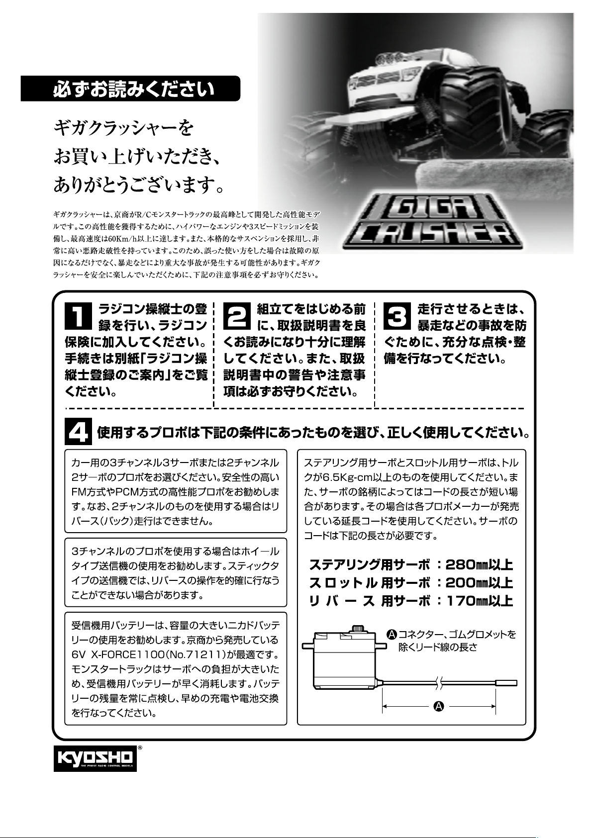
カー用の3チャンネル3サーボまたは2チャンネル2サ
ーボのプロポをお選びください。安全性の高いFM
方式やPCM方式の高性能プロポをお勧めします。な
お、2チャンネルのものを使用する場合はリバース
(バック)走行はできません。
●
3チャンネルのプロポを使用する場合はホイールタ
イプ送信機の使用をお勧めします。スティックタイ
プの送信機では、リバースの操作を的確に行なうこ
とができない場合があります。
●
リバース付プロポをご使用ください。
●
ステアリング用サーボとスロットル用サーボは、ト
ルクが6.5Kg-cm以 上のものを使用してください。
また、サーボの銘柄によってはコードの長さが短い
場合があります。その場合は各プロポメーカーが発
売している延長コードを使用してください。サーボ
のコードは下記の長さが必要です。
・ステアリング用サーボ:280mm以上
・スロットル用サーボ:200mm以上
・リバース用サーボ:170mm以上
●
受信機用バッテリーは、容量の大きいニカドバッテ
リーの使用をお勧めします。京商から発売されてい
る6V X-FORCE1100(No.71211)が最適です。
●
Choose a 3-channel 3-servo or 2-channel 2-servo
radio control system for R/C cars. High performance
FM and PCM radio systems are recommended for
better safety. Please note that the reverse function
cannot be used with a 2-channel 2-servo radio system.
●
A wheel-type transmitter is recommended if using a 3-channel
3-servo radio system. Stick-type transmitters may not provide
precise control of the reverse function in some cases.
●
Use radio set with reverse function.
●
Use steering and throttle servos with at least 6.5Kg-cm of
torque. Also, depending on the brand of servos, some servo
leads may be too short. In this case, please use extension
leads supplied by the servo's manufacturer. The Giga Crusher
requires servo leads of the following lengths:
Steering Servo: 280mm (min.)
Throttle Servo: 200mm (min.)
Reverse Servo: 170mm (min.)
●
Large capacity receiver battery (e.g. Ni-Cd) is recommended.
The Kyosho 6V X-FORCE1100 (No. 71211) is optimal.
■スティックタイププロポ
Stick-type radio set.
■ホイールタイププロポ
Wheel-type radio set.
■単3乾電池(送・受信機用)
AA-size Batteries
(For Transmitter and Receiver)
AAAA
AAAA AAAA
■受信機用ニカドバッテリー
Battery for Receiver
No.71161
6V X-FORCE 600
ニカドバッテリー
Ni-Cd Battery
No.71211
6V X-FORCE1100
ニカドバッテリー
Ni-Cd Battery
■電池ボックス
Battery Box
プロポセットに付いてい
●
るときは必要ありません。
If already included with
the radio, no battery box
needs to be pur-chased
separately.
使用できるサーボ・受信機サイズ
Suitable servos & receiver
■サーボ ■受信機
Servo Receiver
31〜36mm
38〜41mm
18〜20mm
29〜33mm
43〜48mm
模型用燃料と始動用具
Required for engine starting:
2
■燃料
Glow Fuel
No.73802
RCモデルフュール
プロスペックフュール(バギー用)
RC Model Fuel
PRO Spec Fuel (Buggy)
警告
塗料/
筆
Paint / Paint
3
●ボディの塗装には塗料が必要です。
京商では、モデル用塗料、スプレー
を販売していますのでご利用ください。
●For painting the body, use Kyosho
paints for models!
Brush
ガソリンや灯油は
使用禁止
WARNING: Gasoline
or kerosene cannot
be used.
ポリカカラー
POLYCA COLOR
■燃料ポンプ
Fuel Pump
No.96422
クイックフュールポンプ
Quick Fill Fuel Bottle
No.76301〜76711No.2230
京商スプレーカラー
KYOSHO SPRAY COLOR
注意
No.695143
スパークブースター
Spark Booster
スプレーカラーを使用
する場合、缶の説明を
良く読んでください。
CAUTION: Before using
Kyosho Spray Colors,
always read the
explanations!
■プラグヒーター
Plug Heater
No.695142
DC急速充電器
DC Quick Charger
F
U
E
L
T
P
R
N
O
I
O
A
F
P
K
O
Y
H
S
O
S
P
R
O
R
L
A
O
Y
C
R
F
U
E
L
T
P
R
N
O
I
O
A
F
P
K
O
Y
H
S
O
S
P
R
O
R
L
A
O
Y
C
R
2
Page 4
キットの他にそろえる物(2)REQUIRED FOR OPERATION (2)
組立てに必要な工具
Tools required
6
■+ドライバー(大)
Phillips Screwdriver (L)
105mm以上
105mm minimum
■+ドライバー(中、小)
Phillips Screwdriver (M.S)
■−ドライバー(小)
Phillips Screwdriver (S)
80mm以上
80mm minimum
キットに入っている工具
TOOLS INCLUDED
■六角レンチ(1.5mm,2mm,2.5mm,3mm)
Hex Wrench (1.5mm, 2mm, 2.5mm, 3mm)
■カッターナイフ
Sharp Hobby Knife
■ニッパー
Wire Cutters
No.80901
バッテリーチェッカーR(4.8/6.0V)
Battery Checker R (4.8/6.0V)
4.8Vと6Vの受信機
バッテリーに対応。
■ラジオペンチ
Needle Nose Pliers
■キリ
Awl
R
S
L
E
D
O
M
OL
R
T
ON
C
O
I
D
A
R
T
ES
N
I
F
E
H
T
Works with 4.8V and 6V
receiver battery.
使用する工具の取扱いには、
十分注意してください。
CAUTION: Handle tools carefully!
注意
■ゴム系接着剤
Rubber Cement
ゴム系接着剤
No.96154
KYOSHO スペシャルグルー
KYOSHO Special Glue
瞬間接着剤
Instant Glue
No.1948
エアクリーナーオイル
Air Cleaner Oil
R
O
I
L
L
E
N
E
A
I
R
C
KYOSHO
Special Glue
1
9
4
8
T
H
E
F
I
N
E
S
T
R
A
D
I
O
C
O
N
T
R
O
L
M
O
エアクリーナーオイル
D
E
L
S
■十字レンチ(大)
Cross Wrench
No.695101
ナイフエッジリーマー
KNIFE EDGE REAMER
下穴加工が不要で、直接
1mm〜15mmの正確な穴
あけができる工具です。
プロポの準備 RADIO PREPARATION
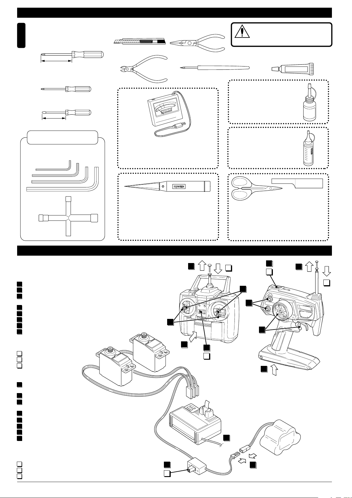
●プロポを下の順番にしたがってセットします。
Set up the radio control system as indicated below.
●始める時
1
送信機に単3乾電池をセットす
る。
2
送信機のアンテナをのばす。
3
電充 電した 受信機 用ニカ ドバ
ッテリーをつなぐ。
4
受信機のアンテナをのばす。
5
トリムを中央にセットする。
6
送信機のスイッチを入れる。
7
受信機のスイッチを入れる。
8
ハンドル/トリガーを動 かして
●終わる時
9
受信機のスイッチを切る。
10
送信機のスイッチを切る。
11
送信機のアンテナを縮める。
●START
1
Insert AA-size batteries into
the Transmitter.
2
Extend the Transmitter aerial.
3
Connect the charged Ni-Cd
battery to the receiver.
4
Unwind the Receiver aerial.
Center the Transmitter trims.
5
Switch "ON" the Transmitter.
6
Switch "ON" the Receiver.
7
Make sure the servos move
8
according to your transmitter
inputs.
●FINISH
9
Switch "OFF" the Receiver.
10
Switch "OFF" the Transmitter.
11
Retract the Transmitter aerial.
サーボ▼
Servo
送信機
Transmitter
ON
OFF
No need to pre-drill!
Drills neat 1mm to 15mm
holes directly!
2
▲
5
1
▼スイッチ
7
9
Switch
6
10
ON
OFF
▼受信機
Receiver
4
ラウンドカッター&サンダー
ROUND CUTTER & SANDER
ボディのカット、仕上
げ用。曲線部分も楽に
作業ができます。
11
8
5
8
3
No.1829
For trimming bodies!
Cutting along curved lines
never was so easy!
ON
6
10
OFF
1
▲バッテリー
Battery
2
11
3
Page 5
組立て前の注意(1) BEFORE YOU BEGIN (1)
組立てる前に説明書を良く読んで、おおよその構造を理解してから組立てに入ってください。
1
Read through the manual before you begin, so you will have an overall idea of what to do.
キットの内容をお確かめください。万一不良、不足がありましたら、お買い求めの販売店にご相談いただくか、当社「ユーザー相談室」までご連絡ください。
2
Check all parts. If you find any defective or missing parts, contact your local dealer or our Kyosho Distributor.
説明書の見かた
3
How to read the instruction manual:
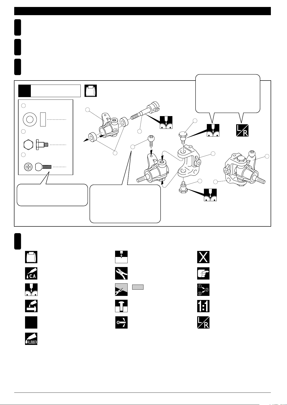
〔説明例Example〕
説明書内では多くのマークが使用
フロントサスペンション
Front Suspension
1
4
5 x 10mm メタル
Metal Bushing
No.4, No.5, No.6
1
されています。マークに注意して
組立てを進めてください。
This instruction manual uses several symbols. Please note them
during the entire assembly.
4
キングピン
5
King Pin
4
5.8mm ピロボール(黒)
6
Pillow Ball (Black)
2
小物部品の名前、原寸図、使用数。
Key Number, Part Name, True-to-scale
Diagram, Quantity Used
説明書に使われているマーク
4
Symbols used throughout the instruction manual, comprise:
使用する袋詰。
Part bags used.
キット内の部品は、ビス類を除いてキー
No.が付けられています。スペアパーツを
購入する時はキーNo.を参照して下さい。
All parts except screws are identified by
key numbers. For purchasing spare parts,
find the key no. of the part needed in the
spare part list and refer to the left column
to look up the corresponding order no.
4
2mm
3
6
2mmの穴をあける(例)。
Drill holes with the specified
diameter (here: 2mm).
5
7
R
L
5
8
別購入品
Must be purchased separately!
2
x2
瞬間接着剤で接着する。
Apply instant glue (CA glue, super glue).
グリスを塗る。
Apply grease.
ネジロック剤を塗る。
Apply threadlocker (screw cement).
2セット組立てる(例)。
Assemble as many times as
specified (here: twice).
ゴム系接着剤で接着する。
Apply rubber cement.
余分をカットする。
Cut off excess.
をカットする。
Cut off shaded portion.
仮止め。
Tentatively tighten.
可動するように組立てる。
Ensure smooth non-binding
movement while assembling.
注意して組立てる所。
Pay close attention here!
番号の順に組立てる。
Assemble in the specified
order.
原寸図
True-to-scale diagram.
左右同じように組立てる。
Assemble left and right sides
the same way.
4
Page 6
組立て前の注意(2) BEFORE YOU BEGIN (2)
キットには、形や長さが違うビスや小物部品が多く入っています。説明書には原寸図がありますので確認してから組立ててください。
5
また、ビス類は多めに入っているものもありますので、予備としてお使いください。
This kit contains screws and hardware in different metric sizes and shapes.
Before using them, check the screws on the true-to-scale diagrams on the left side in each assembly step. Some screws are extras.
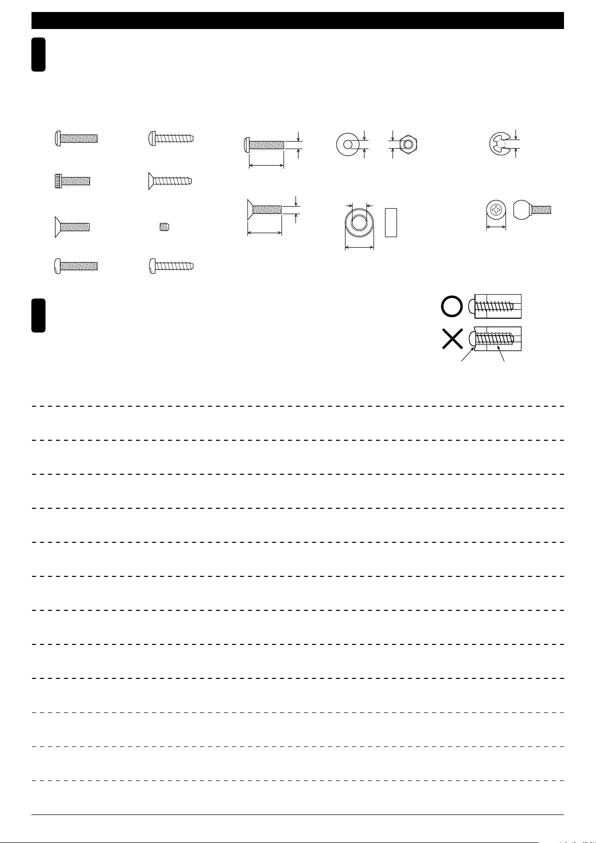
●ビスの種類 SCREWS
ビス Screw
キャップビス
Cap Screw
サラビス
Flat Head (F/H) Screw
ナベビス Screw
TPビスは、部品にネジを切りながらしめつけるビスです。しめこみが固い場合がありますが、
6
部品が確実に固定されるまでしめこんでください。ただし、しめすぎるとネジがきかなくなり
ますので、部品が変形するまでしめないでください。
Self-tapping (TP) screws cut threads into the parts when being tightened. Excessive force may
permanently damage parts when tightening TP screws. It is recommended to stop tightening when
the part is attached or when some resistance is felt after the threaded portion enters the plastic.
TPビス
Self-tapping (TP) Screw
TPサラビス
TP F/H Screw
セットビス
Set Screw
TPナベビス
Self-tapping (TP) Screw
●小物部品のサイズ例 OTHER HARDWARE
3x12mmビス
Screw
12mm
3x12mmサラビス
F/H Screw
3mm
12mm
3mmワッシャー・ナット
Washer・Nut
3mm
5x10mmメタル・ベアリング
Metal Bushing・Bearing
5mm
10mm
3mm
Correct
Wrong
しめすぎ
Overtightened.
E3Eリング
E-ring
3mm
6.8mmピロボール
Pillow Ball
6.8mm
ビスがきかない
The threads are stripped.
MEMO
5
Page 7
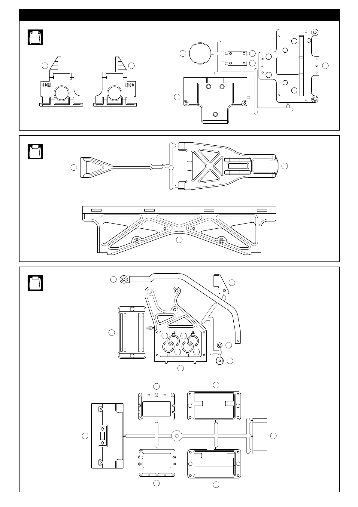
ランナー付プラパーツ配置図(1)/
No.1
ARRANGEMENT OF PLASTIC PARTS ON RUNNERS (1)
1 2
No.2
6
93
120
89
89
41
5
No.3
66
119
79 79
54
40
50
118
79 79
117
46
48
47
55
49
65
6
Page 8
ランナー付プラパーツ配置図(2)/
ARRANGEMENT OF PLASTIC PARTS ON RUNNERS (2)
No.4
No.7
84
96
86
86
85
L R
9
116
121
87
87
10
42
No.8
No.9
68
45
206
77
77
No.10
108
8282
80
80
76 76
112
109
123
94 94
62 62
107
111
110
111
7
Page 9
フロントバルクヘッド
Front Bulkhead
1
4 x 10mm
TP Screw
4 x 12mm
Screw
TPビス
ナベビス
No.1, No.5, No.7, No.A, No.SF DF
又は
角度に注意。
Note the angle.
2
8
1
向きに注意。
Note the direction.
4x10mm
3
3
4x10mm
リヤバルクヘッド
Rear Bulkhead
2
4 x 10mm
TP Screw
4 x 12mm
Screw
TPビス
ナベビス
組立済。
Assembled.
4
4x10mm
4x12mm
8
1
4x10mm
No.1, No.5, No.7, No.A, No.SF DF
又は
1
向きに注意。
Note the direction.
1
4x12mm
角度に注意。
Note the angle.
4x10mm
4x10mm
使用する袋詰。
Part bags used.
8
3
組立済。
Assembled.
3
2
4
4x10mm
注意して組立てる所。
Pay close attention here!
4x10mm
Page 10
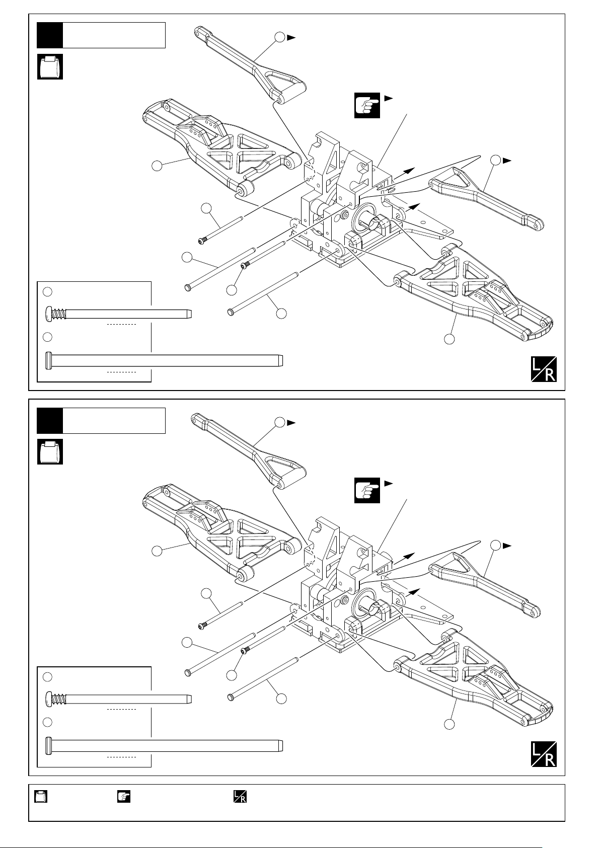
フロントサスペンション
Front Suspension
3
No.2, No.7
6
向きに注意。
Note the direction.
フロント用
For Front
6
5
向きに注意。
Note the
direction.
7
8
3 x 49mm
7
Screw Pin
4 x 80mm
8
Suspension Shaft
4
スクリューピン
サスシャフト
リヤサスペンション
Rear Suspension
No.2, No.7
7
8
2
5
2
6
向きに注意。
Note the direction.
リヤ用
For Rear
6
5
向きに注意。
Note the
direction.
3 x 49mm
7
Screw Pin
4 x 80mm
8
Suspension Shaft
使用する袋詰。
Part bags used.
スクリューピン
サスシャフト
7
8
2
2
注意して組立てる所。
Pay close attention here!
7
8
5
左右同じように組立てる。
Assemble left and right sides the same way.
9
Page 11
フロントサスペンション
Front Suspension
5
18
1
No.7, No.B
< >右側用
< >For Right Side
17
15
13
3
2
16
19
4x12mm
x2
向きに注意。
Note the direction.
4 x 12mm
19
13
6
フランジ付キャップビス
Flanged Cap Screw
ナックルカラー
Knuckle Collar
8 x 16mm
Ball Bearing
ベアリング
フロントサスペンション
Front Suspension
12
8
16
8
18
8
13
14
3
19
4x12mm
2.5 x 14mm
Pin
6mm
Flanged Nut
ピン
フランジナット
No.2, No.7
< >左側用
< >For Left Side
4x12mm
x2
9
10
19
3
14
4
4x12mm
4
19
3
向きに注意。
Note the direction.
13
11
16
13
15
17
2
18
1
右側用
For Right Side
22
3 x 25mm
22
Screw Pin
3 x 36mm
21
Screw Pin
スクリューピン
スクリューピン
21
20
20
左側用
For Left Side
2
フロント用
For Front
21
2
22
使用する袋詰。
Part bags used.
10
2セット組立てる(例)。 仮止め。 番号の順に組立てる。
x2
Assemble as many
times as specified.
Temporarily tighten. Assemble in the
specified order.
注意して組立てる所。
Pay close attention here!
Page 12
リヤサスペンション
Rear Suspension
7
右側用
For Right Side
22
No.2, No.7
20
20
3 x 25mm
22
Screw Pin
3 x 36mm
21
Screw Pin
スクリューピン
スクリューピン
ステアリング
Steering
8
3 x 16mm
F/H Screw
3mm
Flanged Nut
サラビス
フランジ付ナット
21
2
リヤ用
For Rear
2
No.6, No.9, No.A
21
22
25
24
23
約70mm
approx. 70mm
2
左側用
For Left Side
x2
25
24
31
6 x 10mm
Metal Bushing
29
ステアリングピン
Steering Pin
28
ステアリングカラー
Steering Collar
24
5.8mm
ボールエンド
Ball End
23
3 x 83mm
Rod
使用する袋詰。
Part bags used.
メタル
ロッド
4
この穴を使う。
Use this hole.
2
2
2
3mm
ワッシャー
Washer
3 x 10mm
Washer
4
x2
ワッシャー
2
2セット組立てる(例)。
Assemble as many times as specified.
25
4
27
2
5.8mm
Ball
テーパーカラー
Tapered Collar
ボール
4
2
3mm
3x16mm
原寸図。
True-to-scale diagram.
29
28
3mm
26
27
3mm
3x16mm
27
29
28
31
3x10mm
33
3x10mm
3mm
32
31
3mm
34
34
注意して組立てる所。
Pay close attention here!
11
Page 13
ステアリング
Steering
9
No.6, No.A, No.B
フロント用
For Front
3x14mm
3 x 14mm
F/H Screw
4 x 15mm
Screw
35
4 x 10 x 6mm
Collar
10
サラビス
ビス
カラー
リヤサスペンション
Rear Suspension
2
2
2
x2
35
No.6, No.9, No.A
約93mm
approx. 93mm
3x14mm
35
4x15mm
38
37
36
38
37
3 x 14mm
F/H Screw
3 x 16mm
F/H Screw
37
6.8mm
Ball End
27
テーパーカラー
Tapered Collar
6.8mm
38
Ball
36
4 x 107mm
Rod
使用する袋詰。
Part bags used.
サラビス
サラビス
ボールエンド
ボール
ロッド
x2
2
2
27
4
27
4
3x14mm
27
4
3x16mm
2
2セット組立てる(例)。 原寸図。
Assemble as many times as specified. True-to-scale diagram.
リヤ用
For Rear
27
3x14mm
注意して組立てる所。
Pay close attention here!
12
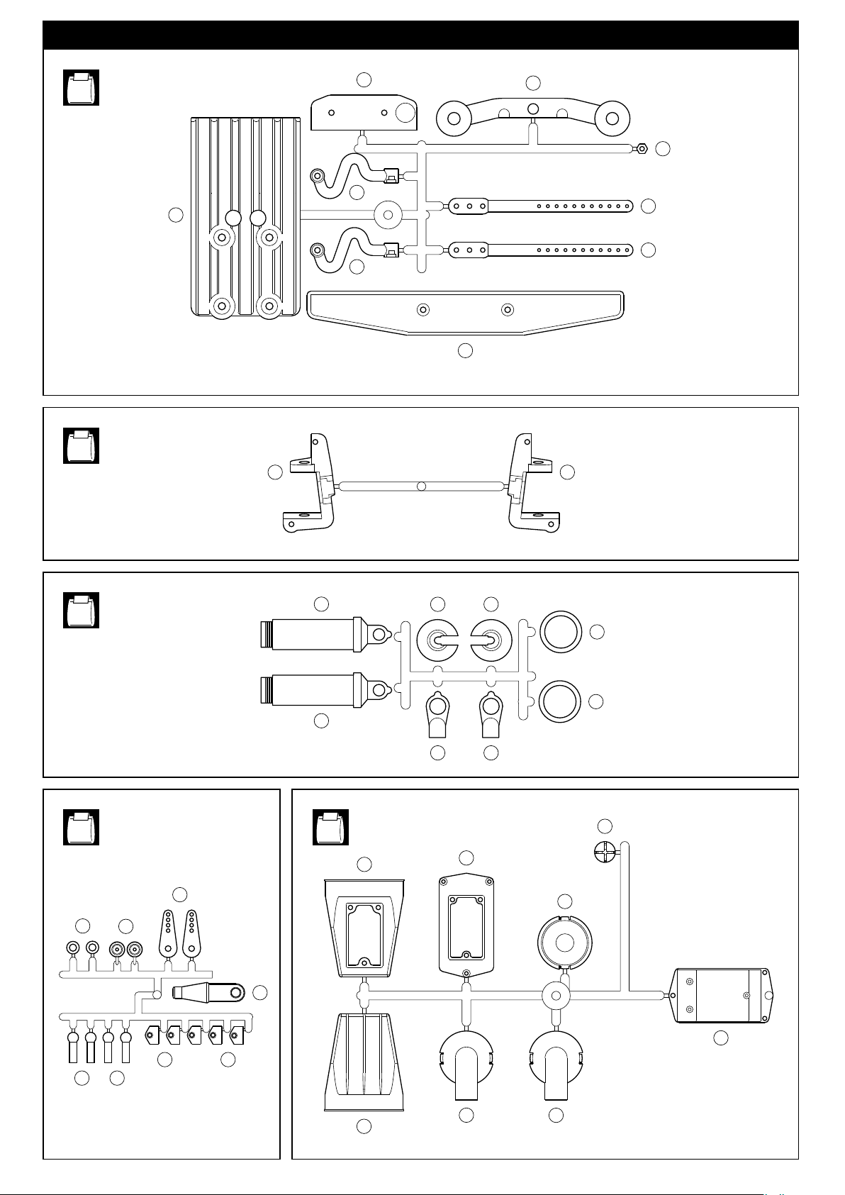
Page 14
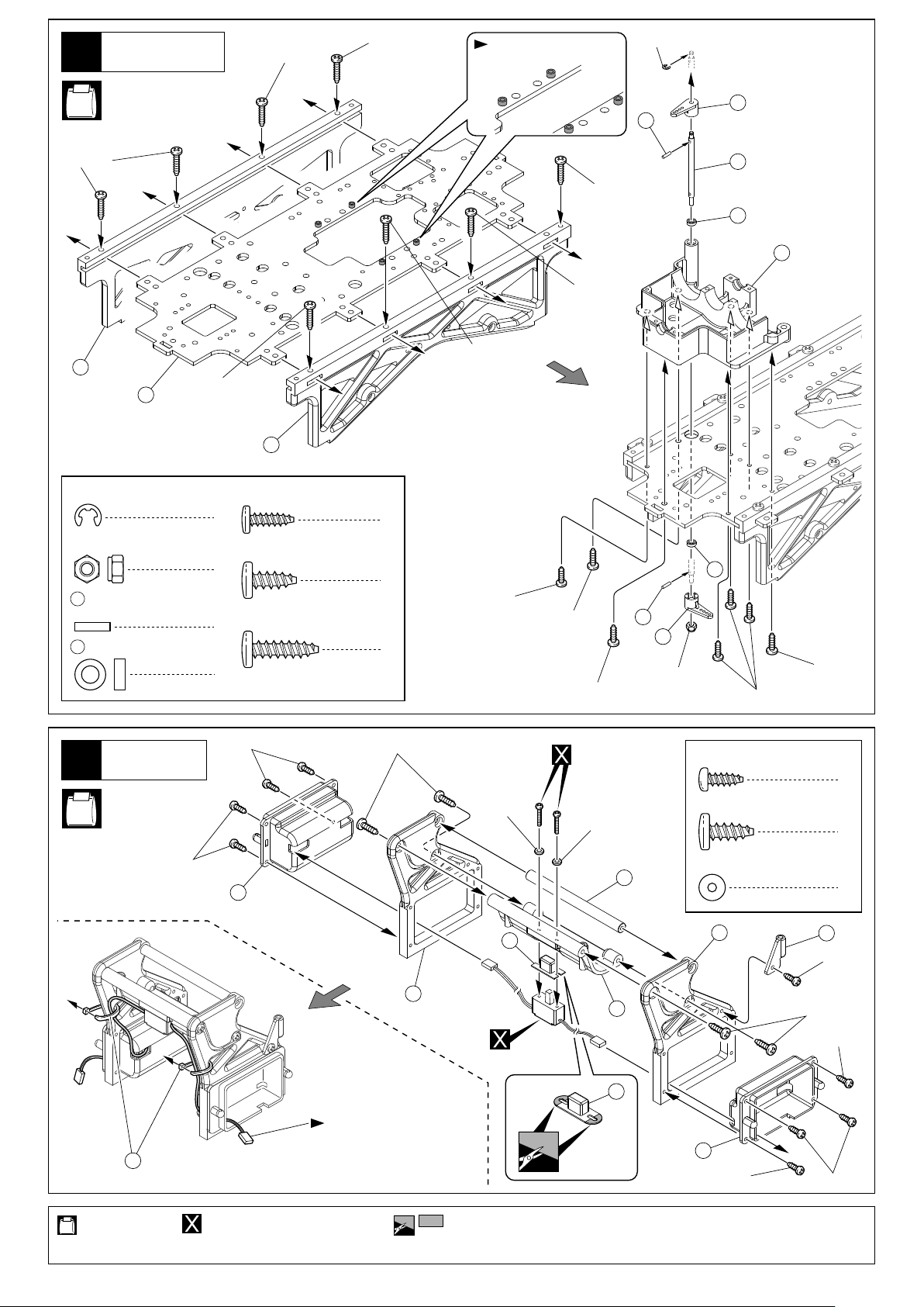
メインシャシー
Main Chassis
11
No.1, No.2, No.5,
No.9, No.A, No.B,
No.SE
又は
DF
4x15mm
4x15mm
上下に注意。
Note the direction.
E2.5
45
44
4x15mm
40
39
E2.5
Eリング
E-ring
3mm
Nylon Nut
44
2 x 8mm
Pin
4 x 7 x 2.5mm
42
ナイロンナット
ピン
4x15mm
プラカラー
Plastic Collar
40
3 x 10mm
TP Screw
1
4 x 10mm
TP Screw
1
4 x 15mm
2
TP Screw
2
TPビス
TPビス
TPビス
43
4x15mm
42
41
4x15mm
4x15mm
4
3mm
42
4x10mm
3x10mm
3
3x10mm
4x10mm
8
4x10mm
44
45
12
ロールバー
Roll Bar
No.3, No.A,
No.SF
又は
3x8mm
53
ナイロンストラップ
Nylon Strap
DF
3x8mm
48
4x10mm
46
コードを図のように通す。
Pass the cord through
as shown.
2mm
52
2mm
47
52
51
3 x 8mm
TP Screw
4 x 10mm
TP Screw
2mm
Washer
TPナベビス
TPビス
ワッシャー
46
49
3x8mm
9
4
2
50
3x8mm
4x10mm
3x8mm
3x8mm
使用する袋詰。
Part bags used.
別購入品。
Must be purchased separately!
をカットする。
Cut off shaded portion.
13
Page 15
13
ロールバー
Roll Bar
No.SF
又は
DF
4 x 10mm
TP Screw
TPビス
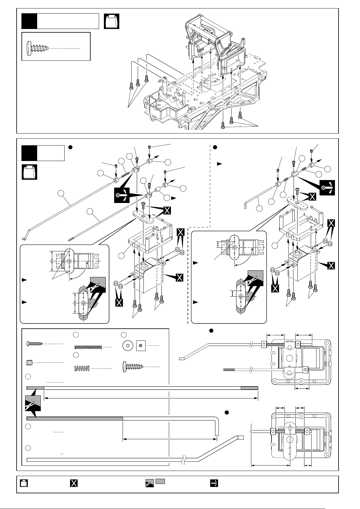
プロポ
Radio
14
No.9, No.A,
No.B
56
6
スロットル用サーボ
Throttle Control Servo
3x3mm
59
57
4x10mm
2x8mm
62
60
2x8mm
62
3x3mm
59
63
燃料チューブを
10mmにカット
して使用。
Cut 10mm from
the fuel tube.
3x3mm
59
リバース用サーボ
Reverse Servo
2チャンネル仕様の場合
は組み立てません。
This assembly is
not used for
2-channel radio.
4x10mm
58
59
3x3mm
61
2x8mm
3x3mm
62
59
61
約13mm
approx. 13mm
約13mm
approx. 13mm
この穴を使う。
Use this hole.
各社サーボホーンを
カットして使用する。
Cut servo horns as
required.
2 x 8mm
TP Screw
3 x 3mm
Set Screw
57
58
TPビス
セットビス
ロッド
Rod
シフトロッド
Shift Rod
90
13mm
13mm
60
スプリング
Spring
3
61
リンケージスプリング
Linkage Spring
5
1
1
54
3x10mm
59
2mm
Stopper
1
3 x 10mm
TP Screw
2
3x10mm
ストッパー
TPビス
125mm
55mm
約7.5mm
approx. 7.5mm
この穴を使う。
Use this hole.
7.5mm
各社サーボホーンを
カットして使用する。
Cut servo horns as
required.
スロットル用サーボ
Throttle Control Servo
5
8
90
リバース用サーボ
Reverse Servo
55
3x10mm
3x10mm
約14mm 約14mm
approx. 14mm approx. 14mm
約19mm
approx. 19mm
約8mm
approx. 8mm
約8mm
approx. 8mm
56
スロットルロッド
Throttle Rod
使用する袋詰。
Part bags used.
14
1
別購入品。
Must be purchased separately!
をカットする。
Cut off shaded portion.
約35mm
approx. 35mm
可動するように組立てる。
Ensure smooth, non-binding movement when assembling.
約7mm
approx. 7mm
Page 16

プロポ
Radio
15
3 x 10mm
TP Screw
TPビス
No.6, No.9,
No.A, No.B
4
約18mm
approx. 18mm
25
24
64
25
x2
24
3 x 14mm
F/H Screw
24
5.8mm
Ball End
27
テーパーカラー
Tapered Collar
5.8mm
25
Ball
64
3 x 30mm
Rod
サラビス
ボールエンド
ボール
ロッド
プロポ
Radio
16
No.B
1
2
この穴を使う。
1
2
1
Use this hole.
各社サーボホーンを
カットして使用する。
Cut servo horns as
required.
3mm
フランジ付ナット
Flanged Nut
90¡
約13mm
approx. 13mm
13mm
ステアリング用サーボ
Steering Control Servo
3x10mm
27
1
3x14mm
2チャンネル仕様の場合は取付けません。
This servo is not installed if using a 2-channel radio.
3mm
65
3x10mm
3 x 10mm
TP Screw
2mm
TPビス
8
3x10mm
3x10mm
先にスロットルレバー
に通しておく。
Pass through Throttle
Lever first.
この穴を使う。
Use this hole.
この穴を使う。
Use this hole.
フロント
Front
この穴を使う。
Use this hole.
3x10mm
コードを通す。
Cords as per
diagram.
使用する袋詰。
Part bags used.
別購入品。 原寸図。
Must be purchased
separately!
True-to-scale
diagram.
2セット組立てる(例)。
x2
Assemble as many
times as specified.
注意して組立てる所。
Pay close attention here!
をカットする。
Cut off shaded portion.
15
Page 17

プロポ
Radio
17
No.3, No.B
プロポの説明書を参考に、
コネクターを接続する。
Connect as per radio
instruction manual.
サーボコードを受信機へ
接続する。
Connect the servo cords
to your receiver.
67
Receiver
受信機
67
66
アンテナ
Antenna
130
67
ボディピン
Body Pin
4
67
コードが地面にこすったり回転部に
触らないように付属のナイロン
ストラップ(小)で固定する。
Use Nylon Strap (Small) to keep
53
cords away from moving parts.
53
53
ナイロンストラップ
Nylon Strap
QRCユニット
QRC Unit
18
No.9, No.A,
No.SF
E3
又は
DF
3x12mm
67
電池ボックス
Battery Box
66
59
2
2
1
3x3mm
3
2
QRCユニットを取付ける。
Install the QRC Unit.
組立済。
Assembled.
3x12mm
2
2
3 x 12mm
Screw
3 x 3mm
Set Screw
59
2mm
Stopper
E3
E-ring
ビス
セットビス
ストッパー
Eリング
4
1
1
1
2チャンネル仕様の時は
図の様に前進に固定します。
When using 2-channel radio,
fix in front as per diagram.
使用する袋詰。
Part bags used.
16
68
番号の順に組立てる。
Assemble in the specified order.
1
先に をしめ込んでおく。
68
First screw on as shown.
68
68
別購入品。 注意して組立てる所。
Must be purchased separately! Pay close attention here!
57
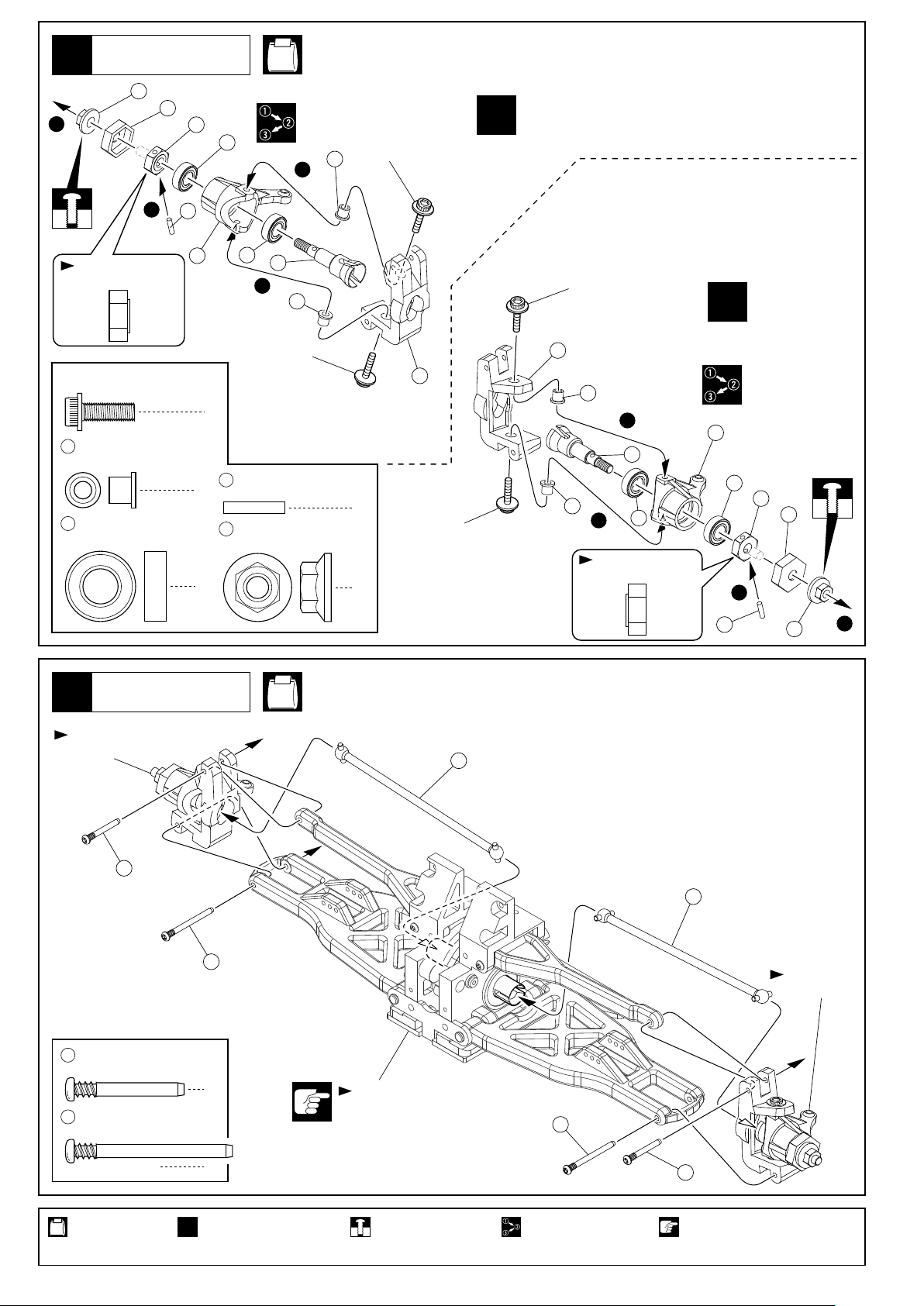
Page 18

シャシー
Chassis
19
4 x 20mm
Screw
4 x 15mm
TP Screw
3 x 14mm
F/H Screw
ビス
TPビス
サラビス
3mm
フランジ付ナット
Flanged Nut
2
27
テーパーカラー
Tapered Collar
4
69
4 x 10 x 11mm
Collar
1
69
No.2, No.6, No.9,
No.A, No.B
1
1
カラー
2
20
69
3mm
4x20mm
4x15mm
フロント用
For Front
シャシー
Chassis
20
70
スイングシャフト(62mm)
Swing Shaft (62mm)
4 x 15mm
TP Screw
TPビス
4x15mm
1
6
4x15mm
No.2, No.B
27
4x15mm
3x14mm
リヤ用
For Rear
使用する袋詰。
Part bags used.
70
4x15mm
4x15mm
注意して組立てる所。
Pay close attention here!
17
Page 19

リンケージの確認
Linkage checking
21
1
プロポのスイッチを入れ、ステア
リングが直進状態になっているこ
とを確認する。曲がっている場合
はロッドの長さを調整する。
Switch the radio ON and check
steering in centered. If steering is
not straight, adjust the length of
the rod.
< >裏面
< >Reverse
4
シフトロッドの位置を確認する。適正でない場合は2mmストッパーの位置を調整する。
(2チャンネル仕様の場合は調整しない。)
Check the position of the Shift Rod. If not correct, adjust the position of the 2mm Stopper.
(No adjustment required using 2-channel radio system).
シフトロッド
Shift Rod
シフトロッド
Shift Rod
前進
Forward Neutral Reverse
ニュートラル
リバース
2mmストッパー
2mm Stopper
59
1
2 3
レバーの向きを確認する。曲がっている場合は2mmストッパーの位置を調整する。
Check the position of the Lever. If not straight, adjust position of the 2mm Stopper.
レバー
Lever
4
3
2
リンケージに約1mmのガタができるようにブレーキ
アジャスターと2mmストッパーの位置を調整する。
Leave about a 1mm gap in the linkage by adjusting
the position of the 2mm Stopper and Brake Adjuster.
ブレーキアジャスター
Brake Adjuster
約1mm
approx. 1mm
使用する袋詰。
Part bags used.
18
2mmストッパー
2mm Stopper
番号の順に組立てる。
Assemble in the specified order.
59
2mmストッパー
2mm Stopper
59
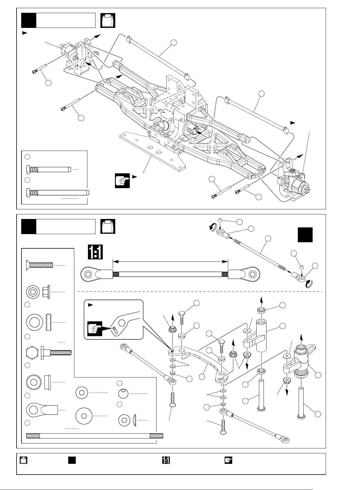
Page 20

サスペンション
Suspension
22
No.5, No.8,
No.SF
又は
DF
3x14mm
71
72
72
3 x 14mm
Set Screw
3 x 12mm
Screw
セットビス
ビス
72
72
3x14mm
4
8
x2
3x12mm
3x12mm
3x12mm
ダンパー
Shock
23
75
Oリング(中)
76
ダンパーエンド
ダンパー
Shock
24
1
オイルを入れる。
Put the oil.
3x12mm
O-ring (M)
Shock End
78
77
8
8
No.8
No.8
74
73
2
伸ばしておく。
Keep expanded.
3
キャップが軽く止
まる所まで締め、
1/2回転ゆるめる。
Tighten the cap
until it slightly stops,
then loosen it for a
1/2nd lap.
75
オイルを少し付ける。
Put a little oil.
4
シャフトをゆっくり押し込む。
Insert the shaft slowly.
余分なオイル
が出る。
Surplus oil
comes out.
76
傷を付けないように
注意する。
Pinch to avoid scratching
the shock shaft.
5
キャップを最後
まで締め込み、
シャフトを伸ばす。
Tighten the cap
firmly, and pull
the shaft.
40mm
x8
x8
使用する袋詰。
Part bags used.
2セット組立てる(例)。
x2
Assemble as many times as specified.
をカットする。
Cut off shaded portion.
19
Page 21

25
83
7.8mm
Ball
ダンパー
Shock
ボール
No.3, No.8
4
83
79
80
81
スプリングを縮めて を入れる。
Compress the spring and install .
82
x8
82
82
ダンパー
Shock
26
3 x 15mm
TP Screw
TPビス
No.B
3x15mm
8
3x15mm
3x15mm
3x15mm
3x15mm
3x15mm
3x15mm
バンパー
Bumper
27
3 x 15mm
TP Screw
TPビス
3x15mm
8
No.4,
No.B
3x15mm
84
86
3x15mm
85
3x15mm
向きに注意。
Note the direction.
86
x2
使用する袋詰。
Part bags used.
20
2セット組立てる(例)。
x2
Assemble as many times as specified.
Page 22

バンパー
Bumper
28
No.4, No.A, No.B,
No.SF
又は
DF
87
87
3 x 12mm
Screw
3 x 10mm
TP Screw
3 x 15mm
TP Screw
ビス
TPビス
TPビス
2
8
4
3x10mm(TP)
3x10mm(TP)
3x15mm
(TP)
4x15mm
4x15mm
3x15mm(TP)
87
3x10mm(TP)
3x15mm(TP)
3x12mm
3x10mm
(TP)
4 x 15mm
TP F/H Screw
3mm
Flanged Nut
TPサラビス
フランジ付ナット
8
2
3スピードミッション
3 Speed Changer
29
3 x 15mm
TP Screw
90
スイングシャフト(68mm)
Swing Shaft (68mm)
TPナベビス
3mm
3x15mm(TP)
87
88
3mm
No.1, No.2,
No.A
3x15mm
89
4x15mm
3x15mm
90
4x15mm
89
4
1
組立済。
Assembled.
使用する袋詰。
Part bags used.
21
Page 23

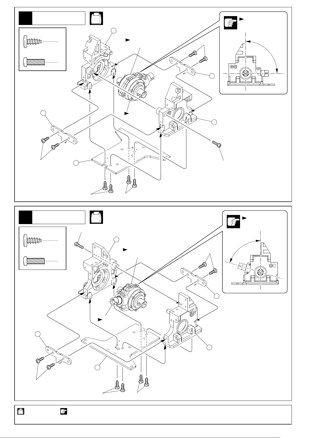
30
エンジン
Engine
デュアルフォースの組み立て
No.2,
DF
又は
No.SF
Assembly of Dual Force
シングルフォースの場合は
27ページから組み立てを
行ってください。
For Single Force, continue
assembly from Page 27..
< >右側用
< >For Right Side
3 x 12mm
Screw
紙1枚分のすきま
をあける。
Insert a sheet of
paper before
installing.
ビス
16
3x12mm
1
右側用
For Right
Side
1.5mm
3mm
91
92
3x12mm
3x12mm
3x12mm
3x12mm
3x12mm
3x12mm
2
左側用
For Left
Side
3x12mm
重要
Important
91
92
< >左側用
< >For Left Side
1.5mm
3mm
ギヤカバー
Gear Cover
31
3 x 10mm
TP Screw
TPビス
マーキング位置
Marking position
クラッチベルのマーキング
位置が図のように一直線上
に並ぶようにしてバックラ
ッシュの調整をする。
Align the markings on the
Clutch Bells in a straight
line as per the diagram
and adjust backlash.
No.1,
3x10mm
No.B
2
93
使用する袋詰。
Part bags used.
22
番号の順に組立てる。
Assemble in the specified order.
注意して組立てる所。
Pay close attention here!
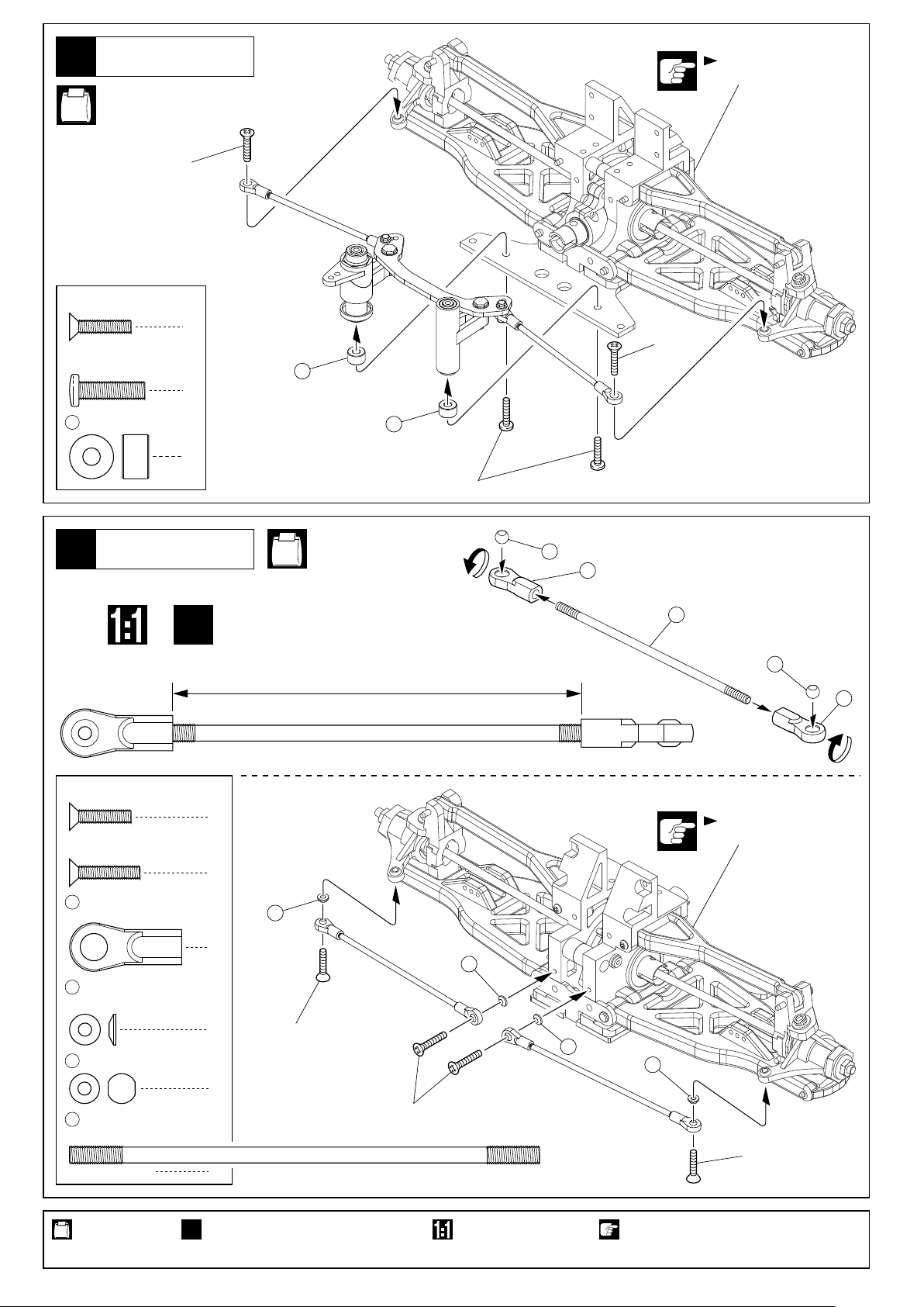
Page 24

スロットルリンケージ
Throttle Linkages
32
57
(S)
< >右側用
< >For Right
No.9, No.A
約44mm
50mm
57
(S)
approx. 44mm
94
57
(L)
2 x 15mm
Screw
3 x 3mm
Set Screw
59
2mm
Stopper
2mm
Nylon Nut
57
ロッド
Rod
ビス
セットビス
ストッパー
ナイロンナット
1
4
4
1
2
< >左側用
< >For Left
94
この穴を使う。
Use this hole.
3x3mm
3x3mm
3x3mm
59
2x15mm
62
3x3mm
59
2mm
62
59
約104mm
59
110mm
57
(L)
approx. 104mm
スロットルリンケージ調整
Throttle Linkage Adjustment
33
調整ビス
Adjustment Screw
2mmストッパー
2mm Stopper
使用する袋詰。
Part bags used.
調整ビス
Adjustment Screw
約1mm 約1mm
approx. 1mm approx. 1mm
アイドリングでエンジンが止まらないように
調整ビスと2mmストッパーの位置を調整する。
Adjust the 2mm Stopper position and Adjustment
Screw so the engine does not stall when idling.
原寸図。
True-to-scale diagram.
をカットする。
Cut off shaded portion.
< >ハイ< >ニュートラル/ブレーキ
< >High Throttle< >Neutral / Brake
可動するように組立てる。
Ensure smooth, non-binding movement when assembling.
23
Page 25

燃料タンク
Fuel Tank
34
3 x 8mm
TP Screw
TPナベビス
63
No.4, No.A,
DF
No.SF
4
又は
燃料チューブを280mmにカットして使用。
Cut the fuel tube to a length of 280mm.
63
燃料チューブを280mmにカットして使用。
Cut the fuel tube to a length of 280mm.
4 x 10mm
TP Screw
TPビス
2
95
95
96
96
3x8mm
3x8mm
マフラー
Muffler
35
2.6 x 10mm
Screw
ビス
4x10mm
4x10mm
No.9, No.11
エンジンを止める時、 を
マフラーに差し込みます。
Insert into the muffler
206
when stopping the engine.
206
206
99
98
2.6x10mm
100
2.6x10mm
101
106
ナイロン
ストラップ
Nylon Strap
102
97
105
4
106
ナイロンストラップ
Nylon Strap
103
104
63
燃料チューブを190mmに
カットして使用。
Cut the fuel tube to 190mm.
x2
使用する袋詰。
Part bags used.
24
2セット組立てる(例)。
x2
Assemble as many times as specified.
瞬間接着剤で接着する。 余分をカットする。
Apply instant glue
(CA glue, super glue).
Cut off excess.
Page 26

マフラー
Muffler
36
図の向きに取付ける。
Attach in same direction as shown.
37
燃料チューブ
Fuel Tube
図の場所を通す。
Pass Fuel Tubes through as shown.
63
燃料チューブ
Fuel Tube
63
燃料チューブ
Fuel Tube
63
燃料チューブ
Fuel Tube
63
燃料チューブ
Fuel Tube
25
Page 27

エアークリーナー
Air Cleaner
38
No.10, No.11,
No.A, No.B
111
113
115
107
108
109
3 x 8mm
TP Screw
3 x 20mm
TP Screw
TPナベビス
TPビス
シャシー
Chassis
39
No.3, No.A,
No.B
116
2x8mm
67
2x8mm
この穴を使う。
Use this hole.
3x20mm
3x20mm
オイルをしみ込ませておく。
114
Soak inner sponge with oil.
115
3
3
110
3x8mm
106
ナイロンストラップでキャブレターに固定する。
Fix it to the Carburetor with Nylon Strap.
116
3x8mm
2x8mm
2x8mm
112
111
この穴を使う。
Use this hole.
87
87
2 x 8mm
Screw
4 x 6mm
Screw
4 x 20mm
Screw
使用する袋詰。
Part bags used.
ビス
ビス
ビス
4
2
67
ボディピン
Body Pin
2
余分をカットする。
Cut off excess.
67
4x20mm
118
119
118
4x6mm
117
4x20mm
119
4x6mm
117
3
67
26
Page 28

30
エンジン
Engine
シングルフォースの組み立て
Assembly for Single Force
No.2, No.SF
3 x 12mm
Screw
ビス
紙1枚分のすきま
をあける。
Insert a sheet of
paper before
installing.
又は
8
DF
3x12mm
3x12mm
3x12mm
3x12mm
91
92
1.5mm
3mm
ギヤカバー
Gear Cover
31
3 x 10mm
TP Screw
使用する袋詰。
Part bags used.
TPビス
No.1,
3x10mm
120
No.B
2
93
27
Page 29

スロットルリンケージ
Throttle Linkages
32
No.9, No.A
50mm
57
57
この穴を使う。
Use this hole.
2 x 10mm
Screw
3 x 3mm
Set Screw
59
2mm
Stopper
ビス
セットビス
ストッパー
約44mm
approx. 44mm
94
59
2x10mm
62
3x3mm
3x3mm
1
2mm
2
2
59
2mm
ナイロンナット
Nylon Nut
57
ロッド
Rod
スロットルリンケージ調整
Throttle Linkage Adjustment
33
調整ビス
Adjustment Screw
2mmストッパー
2mm Stopper
1
1
約1mm
approx. 1mm
アイドリングでエンジンが止まらないように
調整ビスと2mmストッパーの位置を調整する。
Adjust 2mm Stopper position and Adjustment
Screw so the engien does not stall when idling.
< >ハイ< >ニュートラル/ブレーキ
< >High Throttle< >Neutral / Brake
使用する袋詰。
Part bags used.
28
原寸図。
True-to-scale diagram.
をカットする。 可動するように組立てる。
Cut off shaded portion. Ensure smooth, non-binding movement when assembling.
Page 30

燃料タンク
Fuel Tank
34
3 x 8mm
TP Screw
TPビス
No.4, No.A, No.SF
3x8mm
4
又は
DF
63
燃料チューブを210mmにカットして使用。
Cut the fuel tube to a length of 210mm.
122
121
3x8mm
121
35
マフラー
Muffler
No.9, No.11
エンジンを止める時、 を
マフラーに差し込みます。
Insert into the muffler
206
when stopping the engine.
206
206
97
98
3x8mm
99
2.6x10mm
100
3x8mm
2.6x10mm
101
106
ナイロン
ストラップ
Nylon Strap
102
2.6 x 10mm
Screw
使用する袋詰。
Part bags used.
ビス
105
2
瞬間接着剤で接着する。
Apply instant glue
(CA glue, super glue).
103
106
ナイロンストラップ
Nylon Strap
余分をカットする。
Cut off excess.
104
63
燃料チューブを210mmに
カットして使用。
Cut the fuel tube to 210mm.
29
Page 31

マフラー
Muffler
36
図の向きに取付ける。
Attach in same direction as shown.
37
燃料チューブ
Fuel Tube
図の場所を通す。
Pass Fuel Tube through as shown.
マフラーの下を通す。
Pass underneath the muffler.
63
燃料チューブ
Fuel Tube
63
燃料チューブ
Fuel Tube
30
Page 32

エアークリーナー
Air Cleaner
38
No.10, No.11,
No.A, No.B
111
113
115
107
108
109
3 x 8mm
TP Screw
3 x 20mm
TP Screw
TPナベビス
TPビス
シャシー
Chassis
39
No.3, No.A,
No.B
116
2x8mm
67
2x8mm
この穴を使う。
Use this hole.
3x20mm
3
3
110
3x8mm
106
ナイロンストラップでキャブレターに固定する。
Fix to carburetor with nylon strap.
116
3x20mm
3x8mm
2x8mm
2x8mm
オイルをしみ込ませておく。
114
Soak inner sponge with oil.
112
この穴を使う。
Use this hole.
123
87
87
2 x 8mm
Screw
4 x 6mm
Screw
4 x 20mm
Screw
使用する袋詰。
Part bags used.
ビス
ビス
ビス
4
2
67
ボディピン
Body Pin
2
余分をカットする。
Cut off excess.
67
4x20mm
118
119
118
4x6mm
117
4x20mm
119
4x6mm
117
3
67
31
Page 33

デフギヤ
Gear Differential
40
No.2, No.5, No.A,
DF
No.SF
又は
3mm
125
3 x 12mm
Screw
4 x 12mm
Screw
3mm
Flanged Nut
41
< >左側用 < >右側用
< >Left < >Right
ビス
ナベビス
フランジ付ナット
タイヤ
Wheels
4
4
4
4x12mm
4x12mm
3x12mm
125
3mm
同じ向きの物を4つ組立てないようにする。
Assemble 2 wheels for the left and 2 wheels for the right side.
ゴム系ボンドにて接着
してタイヤ内へ入れる。
Apply rubber cement
and install in tires.
124
4x12mm
126
4x12mm
3x12mm
向きに注意。
Note the
direction.
126
向きに注意。
Note the direction.
x2
127
128
x8
128
2個ずつ
入れる。
Insert 2 into
each wheel.
x2
127
使用する袋詰。
Part bags used.
32
Apply instant glue
(CA glue, super glue).
2セット組立てる(例)。瞬間接着剤で接着する。 注意して組立てる所。 ゴム系接着剤で接着する。
x2
Assemble as many
times as specified.
Pay close attention
here!
Apply rubber type glue.
Page 34

42
タイヤ
Wheels
右側用
For right side.
18
右側用
For right side.
18
6mm
フランジナット
Flanged Nut
18
17
左側用
For left side.
17
17
17
18
18
4
左側用
For left side.
塗装
Painting
43
塗装前に、洗剤で油やよごれを洗う。 ウインドウ部分に、内側から
1
Before painting, use a neutral detergent
to remove any oil residues and dirt.
塗分けはパッケージ写真も
3
参考にしてください。
Refer to the pictures on the
box for the color scheme.
京商スプレーカラーで
ボディ内側を塗装する。
Paint the body shell from the inside
using Kyosho’s spray colors.
マスキング
Mask Windows
2
マスキングシートを貼る。
Mask the windows from the inside.
塗装後、ボディ表面の保護ビニール
4
シートをはがしておく。
After painting, remove the protective
film from the body shell.
129
マスキング
Mask Windows
33
Page 35

44
デカール
Decals
図の位置に から順にデカールをはる。1
Apply the decals to the positions indicated in numerical order.
カッコの中は反対側用のデカールナンバーです。
The decal numbers between brackets are only for the opposite side.
番号以外のデカールはパッケージ写真を参考にしてください。
Refer package for applying decals which with out number.
1 2
12
7
6
8 9
( )
5
4 3
( )
10 11
13 14
ボディ
Body Shell
45
67
ボディピン
Body Pin
4
67
67
No.B
67
67
ボディピンは、図のように曲げて
おくと取り外しが楽です。
Slightly bend the body pins as shown
in the diagram for easier removal.
使用する袋詰。
Part bags used.
34
をカットする。
Cut off shaded portion.
Page 36

走行場所
Operating Environment
走行上の注意
Operating Precautions
下記の場所での走行は、故障の原因になりますのでおやめください。
・シャシーにからむような草の生えているところ。
・ぬかるみ、水たまり。
37ページの「取扱いの注意」も必ずお読みください。
エンジン始動とならし運転
Starting and Operating the Engine
別紙の「GS26Rエンジン取り扱い説明書」をよくお読みの上、エンジ
ン始動とならし運転を行ってください。下記の手順で進めます。
1.標準位置の確認
別紙2ページの「エンジンのならし運転前の調整部品標準位置」を確認
します。工場出荷時に標準位置に調整してありますので、この位置で
エンジンを始動してください。
2.リンケージの確認
この取扱説明書の18ページ および23ページ /28ページ を参
照して、各部のリンケージが正しく動作するか確認してください。
3.ならし運転と調整
別紙2ページの「エンジン始動とならし運転」を参照して、ならし運転
を行いながら調整を進めます。デュアルフォースの場合は、必ずエン
ジンを1台ずつ始動してならし運転を行ってください。2台とも始動す
ると、調整がしづらくなります。なお、ギガクラッシャーはチョーク
ボタンを装備しておりません。チョークは、マフラーの排気口をふさ
ぎながらスターターノブを引くことで行います。この際にシリコンチ
ューブ内の燃料がキャブレターに達していることを確認してください。
燃料が達していなければエンジンは始動しません。
また、チョークのし過ぎでも始動が困難になりますのでご注意くださ
い。また、走行させる場合は次の の欄も必ずお読みください。
21
33 33
走行
走行
Operation
* Avoid operating the model in the following conditions as damage to the
model may result.
• Places where the model may become entangled in long grass.
• Mud and water puddles.
* Read page 37 of the instruction manual on operating the model safely.
* After reading the GS26R Engine Instruction Sheet, start the engine and
begin running the model by following the steps below:
1.Check Standard Position Settings
Confirm settings are as per the two page instruction sheet on Engine
Adjustment Settings prior to first run. As the engine adjustment settings
are set correctly at the time of shipment, use these settings when
starting the engine.
2.Check Linkages
Refer to page 18 (No. 21), page 23 (No. 33) and page 28 (No. 33), and
check that all linkages are moving correctly.
3.Learning to Operate and Adjustment
Refer to the 2-page instructions on Starting and Operating the Engine
and adjust engine accordingly. If using the Dual-Force, start and
warm-up the engines one at a time. Starting both engines at once
makes adjustment difficult.
Note the Giga Crusher does NOT include a choke button. To choke the
engine, cover the muffler's exhaust hole with your finger and pull the
starter cord. Check that fuel travels down the silicone tube and into the
carburetor. If fuel hasn't reached the carburetor, the engine will not start.
Also, if too much fuel enters the carburetor, starting may become difficult.
Carefully read the following on operating the model.
エンジンを始動する前に、送信機および受信機用電池の状態をチェッ
クしてください。電池が消耗している場合は必ず新しいものに交換し
てください。
エンジンを始動する前に、送信機を操作してブレーキの効きを確認し
てください。うまく効かない場合は18ページ を参照して、リンケ
ージを調整してください。
デュアルフォースのエンジン始動は、下記の手順で行ってください。
右側のエンジンを始動し、アイドリングが安定するまで暖気運転
1
し、停止させる。
左側のエンジンを始動し、暖機運転をする。
2
左側エンジンのアイドリングが安定したら、右側エンジンを始動する。
3
3チャンネル仕様の場合は、リバース用サーボを操作して前進・後進
のどちらかを選びます。この状態でスロットルを操作すると、走行を
開始します。
3チャンネル仕様のリバース用サーボを操作するときは、必ず下記の条件
で行ってください。この条件外で操作を行うと、故障の原因になります。
エンジンがアイドリング状態であること
1
車体が完全に停止していること
2
スロットルを操作して加速すると、3スピードミッションが作動して
エンジン音が変化します。このタイミングを調整する場合は36ページ
の「シフトタイミングの調整」を参照してください。
必要以上に走行/ブレーキの操作を繰り返すことは故障の原因になり
ますので、おやめください。
21
走行後
After Operation
* Before starting the engine, check the condition of the transmitter and
receiver batteries. If batteries are drained or weak, be sure to replace
with new ones.
*Before starting the engine, check the brake is working and responding
properly to transmitter inputs. If the brake is not working properly, refer
to page 18 (No.21) and adjust linkages.
*Follow the steps below when starting Dual-Force engines.
Start right engine, and once the engine is stable when idling, stop
1
the engine.
Start left engine, and warm the engine up.
2
Once he left engine is stable when idling, start the right engine.
3
* If using a 3-channel radio system, move the third servo (reverse) to
choose reverse or forward. Then, move the throttle control to start
moving the model in that direction.
* When using the 3-channel system with reversing servo, only operate it in
the following conditions. Operating outside these conditions may result
in damage to the model.
Only when the engine is running at idle.
1
Only when the model is completely stopped.
2
*
By moving the throttle control and accelerating, the 3-speed transmission
changes gear which also changes the sound of the engine. To adjust the
timing of gear changes, refer to page 36 on adjustment of gear shift timing.
* Avoid unnecessary and repeated use of the brake as this may damage
the model.
汚れをきれいに落としてください。異物があれば取り除いてください。
各部のビスが緩んでいないか確認してください。
エアクリーナーを点検し、汚れがひどい場合は洗浄または交換してください。
燃料タンク内の余った燃料は抜いてください。また、燃料もれがない
か確認してください。
ギヤやブレーキを点検し、磨耗している場合は新しいパーツに交換してください。
必要に応じて駆動部分に注油してください。
* Remove dirt, grease and any foreign matter that may have collected
during operation.
* Check that all screws are still tight.
* Check the air filter is clean. If it is in bad condition, clean or replace it.
* Remove any unused fuel from the fuel tank. Also check for fuel leaks.
* Check gears and brakes are not worn down and replace if required.
* Oil moving parts in the drive train if required.
35
Page 37

シフトタイミングの調整
3スピードミッションのシフトタイミングは出荷時に適正位置に調整済ですが、シフトタイミングの変更は下記の様に行なってください。
The shift timing of the 3-speed transmission is set at the factory. If you wish to change the settings, adjust as shown in the following illustrations.
シフトタイミングの調整時は、安全のため必ずエンジンを止めて行なってください。
For reasons of safety, do not perform adjustments while the engine is running!
シフトタイミングの調整の前に、エンジンの調整を充分に行なってください。
Adjust the engine before adjusting the gear shift timing.
ADJUSTMENT OF THE GEAR SHIFT TIMING
< >2速目の調整
< >Adjustment for second gear.
2
1
4x4mm
3
155
4x4mm
ロックセットビス
Lock Set Screw
1
φ6ストッパーの4x4mmセットビスをゆるめます。
160
Unscrew the 4x4mm setscrew from the ø6 stopper .
2
1速スパーと 2速スパーを同時に前方へずらします。
158 157
Slide the first and second spur gears forward.
3
2速用クラッチボスに付いている のセットビスで、
152 155
シフトタイミングを調整します。
Adjust the shift timing by installing a set screw on a
clutch boss for second gear .
4
, をもとにもどし、 の4x4mmセットビスを再び
158 157 160
締めます。
Slide the and spur gears back, and then tighten
the 4x4mm set screw .
158 157
152
158 157
160
160
155
フロント リヤ
Front Rear
158 157 152
160
< >3速目の調整
< >Adjustment for third gear.
32150
4x4mm
2
ロックセットビス
Lock Set Screw
1
5x4mm
164
フロント リヤ
Front Rear
シフトタイミング
が早くなる。
Shift timing
becomes quicker.
155150
,
シフトタイミング
が遅くなる。
Shift timing
becomes slower.
147
161 146
, セットビスは2mmの六角レンチで調整し、締め(時計方向)ればシフトタイミン
155 150
グが遅く、ゆるめ(反時計方向)れば早くなります。
Adjust the set screw , using a 2mm hex wrench. For slower shift timing, screw
clockwise. For faster shift timing, unscrew (counterclockwise).
一回の調整量は約10°が目安です。
Ten degrees is sufficient for each adjustment.
2速目と3速目のタイミングがわからなくなってしまった時には、まず3速目のセットビ
スをいっぱいまで締め込み、3速目がシフトアップしない状態で2速目を調整し、それか
ら3速目のセットビスを序々にゆるめて、シフトポイントを探します。
If you confused second and third gear shifting, tighten the third gear set screw firmly to
avoid shifting up. Adjust the second gear first, and then unscrew the third gear set screw
to find the correct shift timing.
155 150
1
5x4mmセットビスをゆるめて、 6mmカップジョイン
トを後方へずらします。
Unscrew the 5x4mm setscrew and slide back the 6mm
cup joint .
2
3スピードシャフトを前方に押して、 3速スパー以
146 161
外を前にずらします。
Push forward the 3-speed shaft and slide all gears
forward except the third spur gear.
3
3速用クラッチボスに付いている のセットビスで、
147 150
シフトタイミングを調整します。
Adjust the shift timing by installing a set screw on a
clutch boss for third gear .
4
をもとにもどし、 6mmカップジョイントをもとの
146 164
位置に固定します。
Slide back the 3-speed shaft and secure the 6mm
cup joint at its original position.
164
164
164
146
150
147
146
メンテナンス
3スピードトランスミッション は、高速で回転するため下記の点に注意してメンテナンスを行ってください。
●
各回転部のベアリングなどは、スムーズに回転するように注油をしてください。
●
シャシーにビスのゆるみがないか定期的に点検し、増し締めしてください。
●
ワンウエイベアリングがロック方向でロックするか定期的に点検し、ロックしない場合は、シャフト及び、ワンウエイベアリングを交換してください。
●
ギヤのごみや小石は、破損の原因になるので常にきれいにしておきましょう。
Note the following in order to ensure smooth operation and long life of the 3-Speed Transmission.
Lubricate the ball bearings to ensure smooth operation.
Regularly check whether the screws on the chassis are firmly tightened, and retighten if necessary.
Regularly check whether the oneway bearing locks into the direction indicated. If it does not lock, replace the shaft or oneway bearing.
Keep the gears clean from dirt and sand to prevent damage.
MAINTENANCE
36
Page 38

注意
OPERATING YOUR MODEL SAFELY取扱いの注意
次のような時、場所では走らせない。思わぬ事故の原因になります。
CAUTION: Do NOT operate the model in the following places and situations:
(Non-observance may lead to accidents!)
●周囲に人がいなくて、広い安全な場所で!
1.自動車道路では走らせない。
2.近くに小さな子供がいたり、人の多い場所では走らせない。
3.民家の近くや公園などでは走らせない。
4.室内やせまいところでは走らせない。
※人にケガをさせる原因になります。また、物をこわしたり、
他人の迷惑になります。
Operate the model in spacious areas with no people
around! Do NOT operate it:
1. on roads!
2. in places where children and many people gather!
3. in residential districts and parks!
4. indoors and in limited space!
*
Non-observance may account
for personal injury and
property damage!
●プロポ関係の電池残量は常にチェックする。
電池が減ってくると電波の送・受信が弱くコントロール
ができなくなり、暴走や衝突の原因なります。
Always check the dry batteries in the radio!
When the dry batteries get weaker, transmission and reception of
the radio decrease. You may lose control of your model when
operating it under such condition. This may lead to accidents!
●近くで無線操縦模型を楽しんでいる人がいる。
同じバンドでの同時走行はできません。電波が混信して
コントロールができなくなり、暴走や衝突の原因なります。
Keep in mind that people around you may also
operate a radio control model!
NEVER share the same frequency
with somebody else at the same
time! Signals will be mixed and
you will lose control of your model.
This may lead to accidents!
01
05
●車の動きがおかしい??とき。
すぐに走行を中止しておかしい原因を調べる、原因不明のまま
走行させると、思わぬ故障や事故の原因になります。
When the model is behaving strangely . . .!
Immediately stop the model and check the reason. As long as the
problem is not cleared, do NOT operate it! This may lead to further
trouble and unforeseen accidents!
事故やケガ等の危険防止のため、次のことを必ずお守りください。
CAUTION: in order to avoid accidents and personal injury,
注意
●燃料の取扱いは、必ず屋外で。
燃料の蒸気、排気ガスは有害です。
Handle fuel ONLY
outdoors!
Vapors and exhausts are
very noxious to health!
●回転している部分に、指や物などを入れない。
高速回転しているのでケガの原因になります。
Do NOT put fingers or any objects inside
rotating and moving parts!
Rotating / moving at high
speed, you may be
seriously injured!
●走行直後は、エンジン、マフラー周辺は高温になって
いるので、すぐにはさわらない。
ヤケドの原因になります。
Right after use, do NOT
touch equipment on the
model such as the engine
and muffler, because they
generate high temperatures!
You may burn yourself seriously touching them!
be sure to observe the following:
●燃料は、模型用グロー燃料を必ず使用する。
ガソリンや灯油の使用は、火災等の事故の原因になります。
ONLY use glow fuel for radio control models!
Because the use of gasoline and kerosene in R/C models ac--
counts for fires, do NOT use them!
●燃料は、引火性があります。
1.火気のあるところや室内では絶対に使用しない。
2.保管は、キャップをしっかりしめ、幼児の手の届かない冷暗
所に置くこと。
3.使用後の空缶は、火中には投げ入れない。爆発の原因になり
ます。
Fuel is highly inflammable and
high-explosive!
1. NEVER use fuel indoors or in places
with open fires and sources of heat!
2. Store fuel ONLY in cool, dry and dark
places out of children's reach! Tightly shut the cap!
3. Do NOT dispose of empty fuel cans into a fire! There is
danger of explosion!
●燃料は、飲んだり、目に入れたりしない。
万一、事故が起きた場合は、吐かせる、洗眼する等をした後、
すぐに医師の診察を受けてください。
NEITHER swallow fuel NOR let it into your eyes!
Immediate measures
should be taken:
if fuel is swallowed, in-duce vomit-ing. If fuel
gets into eyes, rinse
them and consult an
orphamologist!
37
Page 39

EXPLODED VIEW
< >
DF
FM29
67
(Dual Force)
GG009
116
111
GG034
GG009
87
114
R
ダンパー
Shock
72
MA062
71
MA062
72
GG016
18
MA059
X
MA051
126
GG009
85
IF6B
12
A
C
L
86
7
GG020
T
GG009
84
GG009
86
GG0208
MA051
126
MA051-01
128
MA051-01
128
GGH001
127
一部パーツ販売していないパーツがあります。
Note that some parts are not sold as spare parts!
© 2004 KYOSHO CORPORATION / 禁無断転載複製
GG034
113
GG034
112
FM29
67
GG0144
A
デフギヤ
Differential Gear
GG020
7
GG034
108
GG034
GG0208
IF145
10
GG006
89
3スピードミッション
3-Speed Transmission
O
GG0032
GG006
41
GG0173
GG007
119
GG034
107
GG027
51
1700
53
FM29
67
67
P
C
24
W0141V
27
FM29
FM29
69
34
35
LA43
56
67
117
GG029
GG035
42
GG035
45
GG028
GG029
GG033
GG007
24
25
GG031
64
24
49
O
LA43
W0201
LA43
59
GG008
GG007
66
40
J
W0151
93
20
GG034
111
GG006
GG0031
GG024
109
110
R
T
GG034
GG034
59
H
GG034
115
1701
106
W0151
GG035
62
GG020
22
44
GG007
46
F
GG025
89
GG018
26
W0141V
27
25
GG0173
GG006
28
W0201
GG0046
59
IF35
G
W0150
GG035
62
59
45
43
42
IF35
29
IF1459
W0151
57
GG035
W0151
59
57
GG025
GG035
24
IF7
19
13
GG008
47
BS79
52
GG035
GG035
94
GG035
IF35
29
LA43
J
BRG005
94
23
25
65
46
119
GG035
Y
IF35
28
32
W0141V
27
W0201
25
GG031
W0201
GG008
GG007
53
GG007
69
GG029
35
GG028
1700
GG029
GG028
31
GG028
33
31
GG028
GG028
34
D
D
X
GG020
21
MA059
18
14
MA056
IF7
19
IF6B
11
GG0045
MA058
16
BRG005
13
15
MA057
MA058
17
68
GG035
57
GG035
54
118
GG005
H
GG024
20
GG008
66
GG007
P
GG007
GG007
50
I
90
GG026
125
W0141V
27
W0201
25
GG035
60
67
GG022
67
48
FM29
G
124
62
62
FM29
GG008
130
GG019
L
GG035
W0151
59
GG035
Q
クラッチ
Clutch
1705
Y
53
M
92213
63
W0151
59
GG035
58
F
1700
59
V
61
W0151
I
Q
59
GG035
GG035
62
W
K
QRCユニット
QRC Unit
70
W0151
W0151
59
GG035
61
K
91
GG015
92
N
GG023
40
GG015
GG005
126
GG008
55
103
105
GG013
39
MA051
104
GG012
LD29
MA059
18
1700
53
MA051-01
128
128
GG012
97
MA051-01
GG012
1701
106
IF6B
12
GG0031
B
デフギヤ
Differential Gear
127
MA051
126
10
GGH001
IF145
GG0207
98
S
GG0173
V
GG012
1701
106
ダンパー
Shock
W0202
38
27
99
GG009
87
W0141V
N
GG012
GG024
20
GG0045
Z
GG0032
100
63
GG0144
22
21
101
GG012
92213
72
M
U
GG020
GG020
18
GG010
67
MA062
Z
GG0207
27
MA059
63
92213
63
FM29
B
38
GG0046
92213
92213
63
GG035
206
GG010
102
FZW66
95
GG009
96
GG009
116
GG032
88
S
GG016
71
GG009
85
GG009
86
GG009
84
1296
37
GG0173
GG031
36
37
IF1459
19
IF7
19
IF6B
11
BRG005
13
MA058
16
GIGA CRUSHER DUAL FORCE
17
MA057
15
MA058
U
38
1296
IF7
14
W
72
GG009
86
GG0208
W0202
27
MA056
BRG005
13
MA062
GG0208
W0141V
E
E
38
39
Page 40

EXPLODED VIEW
< >
SF
FM29
67
(Single Force)
1701
87
111
GG009
106
GG034
116
GG009
114
R
ダンパー
Shock
72
MA062
71
72
GG016
MA062
MA059
18
X
MA051
126
GG009
85
IF6B
12
A
C
L
86
7 GG020
T
GG009
84
GG009
86
GG0208
MA051
126
MA051-01
128
MA051-01
128
GGH001
127
一部パーツ販売していないパーツがあります。
Note that some parts are not sold as spare parts!
© 2004 KYOSHO CORPORATION / 禁無断転載複製
113
115
GG034
112
GG0144
A
デフギヤ
Differential Gear
GG0207
GG034
GG034
GG034
67
GG0208
F
FM29
IF145
10
GG006
89
3スピードミッション
3-Speed Transmission
O
GG0032
41
GG0173
GG034
107
GG006
GG007
119
GG010
108
GG034
GG034
109
46
1700
53
GG007
101
GG012
GG007
GG027
66
51
FM29
67
G
47
52
GG008
BS79
50
GG007
67
FM29
48
GG008
1705
130
GG012
97
LD29
105
F
104
106
GG012
1701
103
GG012
98
GG012
99
GG012
100
106
1701
102
GG010
63
92213
206
GG035
I
BS65
GG007
GG008
GG007
66
40
J
W0151
GG035
GG008
54
118
GG005
H
GG024
20
67
FM29
クラッチ
Clutch
91
GG015
18
MA059
126
GG015
92
1700
53
M
GG022
90
GG026
G
124
GG019
QRCユニット
QRC Unit
Q
W0151
59
IF6B
GG013
39
1700
53
N
K
GG023
70
GG005
40
12
GG0031
V
P
125
MA051
10
IF145
GG0207
63
92213
ダンパー
Shock
W0202
38
87
W0141V
27
N
V
GG009
GG0144
GG0032
B
W0141V
27
W0201
25
60
GG035
62
62
L
GG035
W0151
59
GG035
63
59
58
92213
W0151
GG035
59
61
W0151
GG035
GG035
62
61
W0151
59
GG035
K
126
デフギヤ
Differential Gear
MA051
S
U
GG0173
20
GG024
GG0045
22
GG020
Q
W
55
GG008
MA051-01
128
MA051-01
128
21
GGH001
127
GG007
46
GG034
123
93
20
110
GG034
GG006
GG0031
GG024
GG025
44
89
120
26
W0141V
27
25
R
H
GG0173
T
GG020
22
GG006
GG006
28
GG018
W0201
GG0046
59
IF35
W0150
GG035
62
59
GG035
45
43
42
IF35
29
IF1459
W0151
GG035
57
GG025
GG035
LA43
24
IF7
19
BRG005
13
94
29
I
GG035
IF35
23
25
J
28
27
25
GG031
W0201
GG008
65
53
GG007
119
69
31
33
31
34
GG029
35
IF35
GG028
32
W0141V
W0201
1700
GG029
GG028
GG028
GG028
GG028
D
67
P
C
24
W0141V
27
67
FM29
35
FM29
69
45
34
GG029
LA43
56
117
GG029
GG035
42
GG035
GG028
GG033
GG007
24
25
GG031
64
24
49
O
LA43
W0201
LA43
59
D
X
GG020
21
MA059
18
14
MA056
IF7
19
IF6B
11
GG0045
MA058
16
BRG005
13
15
MA057
MA058
17
68
GG035
57
GG009
121
72
M
GG020
18
67
MA062
W
GG0207
27
MA059
122
GG009
116
FM29
GG032
88
GG016
71
GG009
85
B
GG009
86
GG009
84
38
1296
37
GG0173
GG0046
36
GG031
37
IF1459
IF7
19
IF6B
11
BRG005
13
MA058
16
15
MA058
17
GIGA CRUSHER SINGLE FORCE
S
U
38
1296
IF7
19
14
MA057
72
GG009
86
GG0208
W0202
27
MA056
BRG005
13
MA062
GG0208
W0141V
E
E
40
41
Page 41

< EXPLODED VIEW >
デフギヤ
Gear Differential
132
GG002
133
IF101
132
IF101
13
BRG005
IF102
142
MA050
136
BS107
134
ORG06
137
135
IF39
139
IF102
138
IF102
136
IF102
134
ORG06
135
IF39
ダンパー
Shock
Shock
77
205
IF102
145
IF102
13
FM185
73
138
139
144
MA050
BRG005
13
BRG005
143
MA050
141
IF103
MA061
140
IF103
13
BRG005
132
131
GG002
IF101
133
IF101
MA061
42
2.6mm
ナット
Nut
75
79
74
80
81
GG007
82
76
83
Page 42

< EXPLODED VIEW >
206
XXXXX
QRCユニット
QRC Unit
GG001-02
185
GG001-09
BRG004
BRG002
GG001-07
183
180
182
186
181
GG001-07
GG001-01
GG001-06
183
BRG002
178
179
BRG004
188
184
177
GG001-02
GG001-08
179
BRG004
BRG006
165
164
GG021
190
GG001-10
13
168
GG001-05
194
IF53
192
GG001-10
BRG005
191
GG001-10
194
IF53
189
GG001-03
193
IF53
193
IF53
179
193
IF53
177
BRG004
179
BRG004
178
GG001-08
GG001-02
GG001-05
GG001-04
クラッチ
Clutch
GG001-11
176
175
174
173
GG001-04
172
GG001-12
171
GG001-04
170
169
96695
145
FM185
GG001-04
13
BRG005
187
GG001-01
196
GG011
195
GG011
204
MA011B
203
MA011B
202
LD70
201
200
KC45
KC45
199
KC45
198
197
GT20
IF64
43
Page 43

< EXPLODED VIEW >
3スピードミッション
3-Speed Transmission
GTW20-2
GG030
166
MA006
MA006
MA006
157
MA007
155
154
153
150
156
GTW20-2
149
MA007
148
MA007
152
MA006
147
MA007
MA007
151
146
GG030
162
BRG014
161
156
MA008
163
GG030
166
MA008
164
165
GG030
GG021
BRG006
165
BRG006
160
GG030
167
GG030
159
158
GT26
156
GTW20-2
GTW20-2
44
Page 44

品番
No.
GG001
-01
GG001
-02
GG001
-03
GG001
-04
GG001
-05
GG001
-06
GG001
-07
GG001
-08
GG001
-09
GG001
-10
GG001
-11
GG001
-12
GG001
-13
GG002
GG003
GG004
GG005
GG006
GG007
GG008
GG009
GG010
GG011
GG012
GG013
GG014
GG015
GG016
GG017
GG018
GG019
GG020
GG021
GG022
GG023
GG024
GG025
GG026
GG027
GG028
パーツ名
Part Names
ギヤボックス
Gear Box
アウトプットギヤ
Output Gear
ブレーキキャリパー
Brake Caliper
ギヤセット
Gear Set
インプットシャフト
Input Shaft
アイドラシャフト
Iddler Shaft
アウトプットシャフト
Output Shaft
シフトピン
Shift Pin
シフトロッド
Shift Rod
ブレーキカムシャフトセット
Brake Cam Shaft Set
スリッパースプリング
Slipper Spring
スリッパーシート
Slipper Sheet
ブレーキハブジョイント
Brake Hub Joint
デフギヤボックス
Differential Box
バルクヘッド
Bulkhead
サスアーム
Suspension Arm
サイドフレーム
Side Frame
3スピードギヤボックス
3-Speed Gear Box
ロールバー
Roll Bar
メカボックス
Receiver Box
バンパー
Bumper
サイレンサー
Muffler
マニホールド
Manifold
チャンバー
Chamber
メインシャシー
Main Chassis
サブシャシー
Sub Chassis
エンジンマウント
Engine Mount
ダンパーステー
Shock Stay
サスプレート
Suspension Plate
ステアリングプレート
Steering Plate
アンダーガード
Under Guard
サスピンセット
Suspension Pin Set
6mmカップジョイント
6mm Cup Joint
スイングシャフト(68mm)1入
Swing Shaft (68mm) 1pcs
スイングシャフト(62mm)1入
Swing Shaft (62mm) 1pcs
スイングシャフト(124mm)2入
Swing Shaft (124mm) 2pcs
スロットルクランクシャフト
Throttle Crank Shaft
クロスメンバー
Cross Member
ロールバーハンドル
Roll Bar Handle
サーボセイバーセット
Servo Saver Set
スペアパーツ SPARE PARTS
内容(キーNo.と入数)
Quantity
187 188
x 1
177
x 2
186
x 1
189
x 1
176 182169 171 173
x 1
168 175
x 1
184
x 1
180 181
x 1
178
x 6
185
x 1
190 191 192
174
172
206
131 132
1 2 x 1
5 6 x 2
40
41 93
46 50 66 79
84 85 96
86 87
101 102
195 196
97 98 99
2.6x10mmビス
2.6x10mm Screw
39
4 x 1
91 92
71
3 x 2
26
124
7 8
164
90
70
20
43
125
51
32 33
x 1
x 2
x 1
x 2
x 1
x 1
x 1
x 1
x 2
x 1
x 1
x 2
x 1
x 2
x 1
x 1
120
x 2
x 1
x 1
x 1
44
x 1
x 1
89
x 1
117 118 119
54 55 6547 48 49
116
121
100 103 104
2221
x 4
x 2
31 34
x 2
x 2
x 1
x 1
x 1
x 2
x 2
★定価
(税込)
840
525
630
630
525
315
1680
630
315
420
420
315
630
525
1050
945
1260
735
1260
945
1365
630
630
1680
4725
630
525
525
420
315
525
840
735
525
525
945
315
525
315
1680
★発送
手数料
210
一律
(税込)
品番
No.
GG029
GG030
GG031
GG032
GG033
GG034
GG035
GGB01
GGB01
-01
GGH001
BS65
BS79
BS107
FM29
FM185
GT20
GT26
GTW20-2
IF6B
IF7
IF35
IF39
IF53
IF64
IF101
IF102
IF103
IF145
KC45
LA43
LD29
LD70
パーツ名
Part Names
サーボセイバースペーサー
Servo Saver Spacer
3スピードシャフト
3-Speed Shaft
タイロッドセット
Tie Rod Set
マフラーステー
Muffler Stay
スロットルロッド
Throttle Rod
エアークリーナーセット
Air Cleaner
リンケージセット
Linkage Set
ボディ
Body
デカール
Decal Set
ホイール
Wheel
タンク(シングルフォース用)
Tank (For SINGLE FORCE)
スイッチブーツ
Switch Boots
ベベルシャフト
Bevel Shaft
ボディピン
Body Pin
ジョイント
Joint
フュールタンク(デュプロ付)
Fuel Tank (Mesh Filter)
2スピード用パイロットシャフト
Pilot Shaft (For 2 Speed Assembly)
2スピード用ワンウェイ
Oneway (For 2 Speed Assembly)
2スピード用ギヤセット
Gear Set (For 2 Speed Assembly)
ナックルアーム
Knuckle Arm
ナックルアームカラー
Knuckle Arm Collar
ステアリングピン
Steering Pin
2.6x14mmシャフト
2.6x14mm Shaft
ブレーキディスクセット
Brake Disk Set
フライホイール(スポーツ)
Flywheel (Sports)
デフシャフトセット
Differential Shaft Set
デフベベルセット
Differential Bevel Set
デフケース
Differential Case
フロントハブキャリア
Front Hub Carrier
スペシャルクラッチ
Special Clutch
5.8mmボールエンド
5.8mm Ball End
シリコンチューブ
Silicone Tube
クラッチベアリング
Clutch Bearing
★FOR JAPANESE MARKET ONLY.
内容(キーNo.と入数)
Quantity
35 69
x 2
166
64
156
x 1
x 2
x 1
x 1
x 1
x 1
x 2
x 4
x 1
x 1
x 1
x 1
x 2
x 4
163160 167
146
4x4mmセットビス
4x4mm Set Screw
Eリング(E5.0)
E-ring (E5.0)
23 36
x 2
88
x 1
56
x 1
110 113 114107 108 109
115111
x 2
58 60
x 1
6145 68
42
57
x 394x 462x 5
2x8mmビス
2x8mm Screw
2x15mmビス
2x15mm Screw
2x10mmビス
2x10mm Screw
2mmナイロンナット
2mm Nylon Nut
マスクシール
129
x 1
Masking Sheet
デカール
Decal Set
127
122
52
137
67
145
95
198
159
157 158
11 12
19
28 29
135
193
197
132 133
136
140 141
910x 1
199 201
24
105
201 202
x 2
x 1
x 3
x 6
x 10
x 2
x 1
x 1
x 1
x 4
x 10
x 4
x 1
x 2
x 12
x 2
x 1
x 1
x 2
x 2
x 1
x 1
x 1
x 1
194
x 2
138 139
★定価
(税込)
315
525
525
735
420
1680
840
4200
1680
1680
1050
294
578
158
630
1575FZW66
840
2625
735
840
840
473
189
1260
1260
788
420
525
788
1365
315
420
609
★発送
手数料
210
一律
(税込)
45
Page 45

品番
No.
MA006
MA007
MA008
MA011B
MA050
MA051
MA051
-01
MA056
MA057
MA058
W0141V
W0201
ORG06
1296
1700
KP/KY
1701
KP/KY
1705
92213
92304-2
パーツ名
Part Names
2スピードカムセット
2-Speed Cam Set
3スピードカムセット
3-Speed Cam Set
3速スパーギヤ
3rd Spur Gear
3スピード用クラッチベル
Clutch Bell (for 3-Speed/MF/GG)
ベベルギヤセット(MFレディセット用)
Bevel Gear Set (
タイヤ/インナースポンジ(MFレディセット用)
Tire/Inner Sponge (
For MAD FORCE RS
For MAD FORCE RS
インナースポンジ(4入)
Inner Sponge (4 pcs)
ホイールシャフト
Wheel Shaft
ホイールストッパー
Wheel Stopper
ホイールスペーサー
Wheel Spacer
ホイールナット
Wheel Nut
ダンパーセット
Shock Set
ダンパーピボット
Shock Pivot
3x6mmテーパーワッシャー
3x6mm Tapered Washer
リンケージストッパー(2mm)
Linkage Stopper (2mm)
5.8mmボール
5.8mm Ball
6.8mmボール
6.8mm Ball
Oリング(P6)
O-ring (P6)
6.8mmボールエンド
6.8mm Ball End
蛍光ストラップ(S)
Fluorescent Strap (S)
蛍光ストラップ(M)
Fluorescent Strap (M)
アンテナパイプ
Antenna Pipe
燃料チューブ
Fuel Tube
HDエアークリーナースポンジ(4個入)
HD Air Cleaner Sponge (4pcs)
7.8mmボール
7.8mm Ball
スペアパーツ SPARE PARTS
内容(キーNo.と入数)
Quantity
152 153 154 155
147 148 149 150 151
156 161
203
x 1
142 143 144
)
126 128
)
128
x 4
14
x 2
15
x 2
16 17
18
x 4
73 74 75 76 77
80 81 82 83
72
x 4
27
x 10
59
x 10
25
x 10
38
x 10
134
x 15
37
x 12
53
x 18
106
x 18
130
x 6
63
x 1
114
x 4
83
x 10
x 1
x 2
x 2
204
x 1
x 1
x 1
205
x 1
x 2
★定価
(税込)
1575
735
735
2310
1680
2310
630
683
578
368
263MA059
1995MA061
315MA062
473
683W0151
735
735W0202
420
420
(各)
189
(各)
263
525
700
1050
42092846
★発送
手数料
210
一律
(税込)
★FOR JAPANESE MARKET ONLY.
品番
No.
BRG004
BRG005
BRG006
BRG014
BRG022
キットの部品の一部にはスペアパーツとして販売していない物があります。
京商ではオプションパーツを販売していますのでお買い求めください。
Some of the parts included are not available as spare parts. Purchase
optional parts instead.
パーツ名
Part Names
8x14mmベアリング
8x14mm Ball Bearing
8x16mmベアリング
8x16mm Ball Bearing
6x12mmベアリング
6x12mm Ball Bearing
10x15mmベアリング
10x15mm Ball Bearing
6x10mmベアリング
6x10mm Ball Bearing
20x32mmベアリング
20x32mm Ball Bearing
内容(キーNo.と入数)
Quantity
179
x 4
13
x 2
165
x 2
162
x 2
183
x 2
170
x 1
★定価
(税込)
1050
683
1050
1260
1050
73596695
★発送
手数料
210
一律
(税込)
46
Page 46

品番
No.
BSW77
IFW32BL
IFW32GR
IFW32W
MAW005
IFW117
IFW117-01
IFW118
W0201
1776
1790BL
1790R
1790SG
1796
BL/R
1829
1876
1948
パーツ名
Part Names
アジャスターカラー
Adjuster Collar
スプリング(S)ブルー・ミディアム
Spring (S) Blue ¥ Medium
スプリング(S)グリーン・ソフト
Spring (S) Green ¥ Soft
スプリング(S)ホワイト・ハード
Spring (S) White ¥ Hard
ウルトラソフトスプリング
Ultra Soft Spring
LSDギヤセット
TCD Gear Set
LSDギヤオイル
TCD Gear Oil
LSDファイナルギヤセット
TCD Final Gear Set
5.8mmスチールボール
5.8mm Steel Ball
ピットボックス
Pit Box
カラーシリコンチューブ(ブルー)
Color Silicone Tube (Blue)
カラーシリコンチューブ(レッド)
Color Silicone Tube (Red)
カラーシリコンチューブ(スモークグレー)
Color Silicone Tube (Smoke Grey)
スパイラルチューブ
Spiral Tube
ラウンドカッター&サンダー
Hobby Shears & Sander
燃料フィルター
Fuel Filter
エアークリーナーオイル
Air Cleaner Oil
オプションパーツ OPTIONAL PARTS
内容(キーNo.と入数)
Quantity
ダンパー2本分
For 2 set of shock.
2個入
2 pcs.
2個入
2 pcs.
2個入
2 pcs.
ダブルダンパー用スプリング 4本入
Spring Set for Double Damper (4 pcs.).
LSDギヤ専用オイル
For TCD Gear.
LSDギヤとデフケース、
ファイナルベベルギヤのセット
Includes TCD Gear Set, Diff. Case and
Final Bevel Gear (complete differential).
サイズ / 420x240x330mm
Size / 420x240x330mm
サイズ / 2.3x1000mm
Size / 2.3x1000mm
サイズ / 2.3x1000mm
Size / 2.3x1000mm
サイズ / 2.3x1000mm
Size / 2.3x1000mm
曲線部分のボディカットが容易
Handy tool for round cut
燃料のゴミをシャットアウト
Shuts out dirt from fuel
★定価
(税込)
525
945
945
945
1260
7875
525
10500
735
7140
420
420
420
(各)
735
1050
1050
1050
★発送
手数料
210
一律
(税込)
品番
No.
6v X-FORCE 600ニカドバッテリー
71161
6v X-FORCE 600 Ni-Cd Battery
6v X-FORCE 1100ニカドバッテリー
71211
6v X-FORCE 1100 Ni-Cd Battery
BPモデルエンジンフュール
73001
Glow Fuel
BP燃料ピークパワー
73401
BP Fuel Peak Power
スペシャルテーパーリーマー
80311
Special Taper Reamer
ロッキングジグ&レンチ
80312
Locking Jig & Wrench
耐熱マフラージョイントパイプ
92060
Muffler Joint Pipe
LSDギヤオイル
92201
TCD Gear Oil
ロックタイト(中強度)
94402
Loctite (medium strength)
シリコンシール
96152
Silicone Seal
パワークリーナー
96405
Power Cleaner
クイック フュールポンプ 500cc
96422
Quick Fuel Pump 500cc
SPベアリングリキッド
96625
Special Bearing Liquid
トルネード アフターランオイル
607011
Tornade After Run Oil
ナイフエッジリーマー
695101
Knife Edge Reamer
DC急速充電器
695142
DC Quick Charger
スパークブースター
695145
Spark Booster
パーツ名
Part Names
★FOR JAPANESE MARKET ONLY.
内容(キーNo.と入数)
Quantity
受信機用電源
for receiver
受信機用電源
for receiver
R/Cエンジン用グロー燃料
Glow fuel for R/C Engine
ボディの穴開けに最適
Best tool for holing bodies.
十字レンチ+クランクロック
Cross wrench + plug locker.
2個入
2 pcs.
ネジの緩み防止
Screw cement.
給油ポンプ
aid for fueling
ベアリング本来の性能を発揮
Retrieves potentiality of Bearing.
使用後のエンジンメンテナンス用
For Engine maintenance.
ボディ等の穴あけ加工に最適
To drill holes of the body.
スパークブースター用充電器
DC Charger for Glow Heater.
プラグヒート用(バッテリー付き)
Glow Heater (battery included)
★定価
(税込)
3990
4200
1050
3780
1890
840
945
1260
945
840
840
1260
1050
630
2100
1995
2730
★発送
手数料
210
一律
(税込)
47
Page 47

SCREW・NUT etc.ビス・ナット類
品番
No.
1101
1102
1103
1104
1105
1106
1107 2.6x25 10 pcs
1110
1111
1112
1113
1114
1115
1117
1118
1119
1120
1121
1122
1123
1168
1197
1124
1125
1126
1127
1128
1129
1130
1131
1196 2.6x18
サイズ(mm)
Size (mm)
ナベビス
Round Head Screw
2x6・2x8・2x10・2x15 5 each 10 each
2.6x8・2.6x10・2.6x12・2.6x14
3x4・3x6・3x8・3x10・3 x12
3x14・3x16・3x18・3x20
4x6・4x8・4x10・4x12
3x22・3x24・3x26・3x28
バインドビス
Bind Screw
2.6x4・2.6x6・2.6x8・2.6x12
3x4・3x6・3x8・3x10・3x12
3x14・3x16・3x18・3x20
4x6・4x8・4x10・4x12
3x22・3x25・3x28・3x30
4x15・4x18・4x20・4x22
サラビス
Flat Head Screw
2.6x6
2.6x8・2.6x10・2.6x12・2.6x14
3x6・3x8・3x10・3x12
3x14・3x16・3x18・3x20
4x8・4x10・4x15・4x20
3x22・3x24・3x26・3x28
3x30・3x32・3x34・3x35
4x12
4x6
キャップビス
Cap Screw
2x8・2x10・2x12・2x14
2.6x8・2.6x10・2.6x12・2.6x14
3x8・3x10・3x12・3x14
3x15・3x16・3x18・3x20
3x25・3x30・3x35・3x40
4x10・4x15・4x20
4x25・4x28・4x30
4x35・4x40・4x45
入数(各)
QUANTITY
★210
(税込)
5 each
5 each
5 each
5 each
5 each
★210
(税込)
5 each
5 each
5 each
5 each
5 each
5 each
★210
(税込)
10 pcs
5 each
5 each
5 each
5 each
5 each
5 each
10 pcs
10 pcs
★210
(税込)
2 each
2 each
2 each
2 each
2 each
2 each
2 each
2 each
4 pcs
品番
No.
1132
1133
1134
1135
1136
1137
1140
1141
1142
1143
1147
1148
1149
1150
1153
1154
1157
1160
1161
1162
1163
1164
1165 3x20・3x25 3 each
1166
1167
サイズ(mm)
Size (mm)
ナベタッピングビス
Round Head Self-Tapping Screw
2x4・2x6・2x8・2x10 5 each
2.6x6・2.6x8・2.6x10・2.6x12
3x6・3x8・3x10・3x12・3x14
3x15・3x16・3x18・3x20
3x25・3x30・3x35
2.6x14・2.6x15・2.6x16・2.6x18
バインドタッピングビス
Bind Self-Tapping Screw
2.6x6・2.6x8・2.6x10・2.6x12
3x6・3x8・3x10・3x12・3x14
3x15・3x16・3x18・3x20
4x10・4x15・4x18
サラタッピングビス
Flat Head Self-Tapping Screw
2.6x6・2.6x8・2.6x10・2.6x12
3x6・3x8・3x10・3x12・3x14
3x15・3x16・3x18・3x20
4x15・4x20・4x25
フランジ付キャップビス
Flanged Cap Screw
3x6・3x8・3x10
4x8・4x10・4x12
サラ小丸ビス
Oval Head Screw
2x8・2x10
セットビス
Set Screw
3x6・3x12・3x14・3x16
3x3・3x4・3x5・3x10
4x4・4x5・4x8・4x12
5x4・5x5・5x6
5x30・5x40
4x8(平先)
4x20
入数(各)
QUANTITY
★210
(税込)
5 each
5 each
5 each
5 each
5 each
★210
(税込)
5 each
5 each
5 each
5 each
5 each1151 4x8・4x12
★210
(税込)
5 each
5 each
5 each
5 each
★210
(税込)
2 each
2 each
★210
(税込)
10 each
★210
(税込)
3 each
3 each
3 each
3 each
3 each
10 pcs
2 pcs
品番
No.
1171
1172
1174
1175
1177
1178
1179
1181 5mm 4 pcs
1183 3mm(薄) 5 pcs
1180
1185
1186
1189
1380
1381
1382
1383
1384
1385
1386
1387
1390
ここに明記された以外のビス、ナット等は
『ユーザー相談室』にお問い合わせください。
★ FOR JAPANESE MARKET ONLY.
径
mm
ナット
Nut
2mm・2.6mm
3mm・4mm
フランジ付ナット
Flanged Nut
3mm
4mm
ナイロンナット
Nylon Nut
2.6mm
3mm
4mm
フランジ付ナイロンナット
Flanged Nylon Nut
4mm
ワッシャー
Washer
2mm・2.6mm・3mm
4mm・5mm
2.6mm
Eリング
E-Clips
E1.5
E2.0
E2.5
E3.0
E4.0
E5.0
E6.0
E7.0
E10.0
入数(各)
QUANTITY
★210
(税込)
10 each
★210
(税込)
10 pcs
10 pcs
★210
(税込)
5 pcs
5 pcs
5 pcs
★210
(税込)
5 pcs
★210
(税込)
10 each
10 each
10 pcs
★158
(税込)
10 pcs
10 pcs
10 pcs
10 pcs
10 pcs
10 pcs
10 pcs
6 pcs
6 pcs
品番
No.
SIL0100
SIL0150
SIL0200
SIL0250
SIL0300
SIL0350
SIL0400
SIL0450
SIL0500
SIL0550
パーツ名
Part Names
シリコンオイル(100)
Silicone Oil (100)
シリコンオイル(150)
Silicone Oil (150)
シリコンオイル(200)
Silicone Oil (200)
シリコンオイル(250)
Silicone Oil (250)
シリコンオイル(300)
Silicone Oil (300)
シリコンオイル(350)
Silicone Oil (350)
シリコンオイル(400)
Silicone Oil (400)
シリコンオイル(450)
Silicone Oil (450)
シリコンオイル(500)
Silicone Oil (500)
シリコンオイル(550)
Silicone Oil (550)
内容(
ダンパー用
for shocks.
キーNo.と入数
Qty.
京商ホームページ
http://www.kyosho.co.jp/
メーカー指定の純正部品を使用して
安全にR/Cを楽しみましょう。
48
)
★定価
(税込)
各630 210
(税込)
★発送
手数料
一律
品番
No.
シリコンオイル(600)
SIL0600
Silicone Oil (600)
シリコンオイル(700)
SIL0700
Silicone Oil (700)
シリコンオイル(800)
SIL0800
Silicone Oil (800)
シリコンオイル(900)
SIL0900
Silicone Oil (900)
シリコンオイル(1000)
SIL1000
Silicone Oil (1000)
シリコンオイル(1100)
SIL1100
Silicone Oil (1100)
シリコンオイル(1200)
SIL1200
Silicone Oil (1200)
シリコンオイル(1300)
SIL1300
Silicone Oil (1300)
シリコンオイル(2000)
SIL2000
Silicone Oil (2000)
シリコンオイル(3000)
SIL3000
Silicone Oil (3000)
パーツ名
Part Names
★FOR JAPANESE MARKET ONLY.
内容(
ダンパー用
for shocks.
デフ用
for diffs.
キーNo.と入数
Qty.
)
★定価
(税込)
各630 210
(税込)
★発送
手数料
一律
品番
No.
シリコンオイル(4000)
SIL4000
Silicone Oil (4000)
シリコンオイル(5000)
SIL5000
Silicone Oil (5000)
シリコンオイル(6000)
SIL6000
Silicone Oil (6000)
シリコンオイル(7000)
SIL7000
Silicone Oil (7000)
シリコンオイル(10000)
SIL10000
Silicone Oil (10000)
シリコンオイル(20000)
SIL20000
Silicone Oil (20000)
シリコンオイル(30000)
SIL30000
Silicone Oil (30000)
シリコンオイル(40000)
SIL40000
Silicone Oil (40000)
シリコンオイル(50000)
SIL50000
Silicone Oil (50000)
シリコンオイル(100000)
SIL100000
Silicone Oil (100000)
パーツ名
内容(
Part Names
デフ用
for diffs.
THE FINEST RADIO CONTROL MODELS
キーNo.と入数
Qty.
)
京商株式会社
〒243-0034 神奈川県厚木市船子153
●ユ−ザ−相談室直通電話 046-229-4115
お問い合わせは:月曜〜金曜(祝祭日を除く) 10:00〜18:00
PRINTED IN JAPAN61920407-1
★発送
★定価
手数料
(税込)
各630 210
(税込)
一律
R
 Loading...