

Page 1
※ご使用前にこの説明書を良くお読みになり十分に理解してください。
Before beginning assembly, please read these instructions thoroughly!
THE FINEST RADIO CONTROL MODELS
R
組立/取扱説明書
INSTRUCTION MANUAL
1:10 SCALE
RADIO CONTROLLED .12-.15 ENGINE POWERED TOURING CAR SERIES CHASSIS KIT
目 次 INDEX
●キットの他にそろえる物 REQUIRED FOR OPERATION
●プロポの準備RADIO PREPARATION
●組立て前の注意 BEFORE YOU BEGIN
●ランナー付プラパーツ配置図 ARRANGEMENT OF PLASTIC PARTS ON RUNNERS
●本体の組立て ASSEMBLY
●取扱いの注意 OPERATING YOUR MODEL SAFELY
●分解図 EXPLODED VIEW
●スペアパーツ・オプションパーツリスト SPARE PARTS & OPTIONAL PARTS
安全のための注意事項
この無線操縦模型は玩具ではありません!
●この商品は高い性能を発揮するように設計されています。
組立てに不慣れな方は、模型を良く知っている人にアド
バイスを受け確実に組立ててください。
●小さい部品があるので、組立て作業は、幼児の手がとど
かない所で必ず行ってください。
●動かして楽しむ場所は万一の事故を考えて、安全を確認
してから責任をもってお楽しみください。
●組立てた後も、説明書がいつでも見られるように大切に
保管してください。
※製品改良のため、予告なく仕様を変更する場合があります。 *SPECIFICATIONS ARE SUBJECT TO BE CHANGED WITHOUT NOTICE.
2003 KYOSHO CORPORATION/禁無断転載複製
UNDER SAFETY PRECAUTIONS
This radio control model is not a toy.
●First-time builders should seek the advice of experienced modellers
before commencing assembly and if they do not fully understand
any part of the construction.
●Assemble this kit only in places out of children's reach!
●Take care before operating this model.
You are responsible for this model's assembly and safe operation!
●Always keep this instruction manual ready at hand for quick
reference, even after completing the assembly.
2 〜 3
5 〜 6
7 〜 30
31
32 〜 33
34 〜 37
No. 31581
3
4
Page 2
※ご使用前にこの説明書を良くお読みになり十分に理解してください。
Before beginning assembly, please read these instructions thoroughly!
FW‑05
FW‑05
ADDITIONALINSTRUCTIONSHEET
追加説明書
THE FINEST RADIO CONTROL MODELS
No.31581B
R
17ページ
Page17
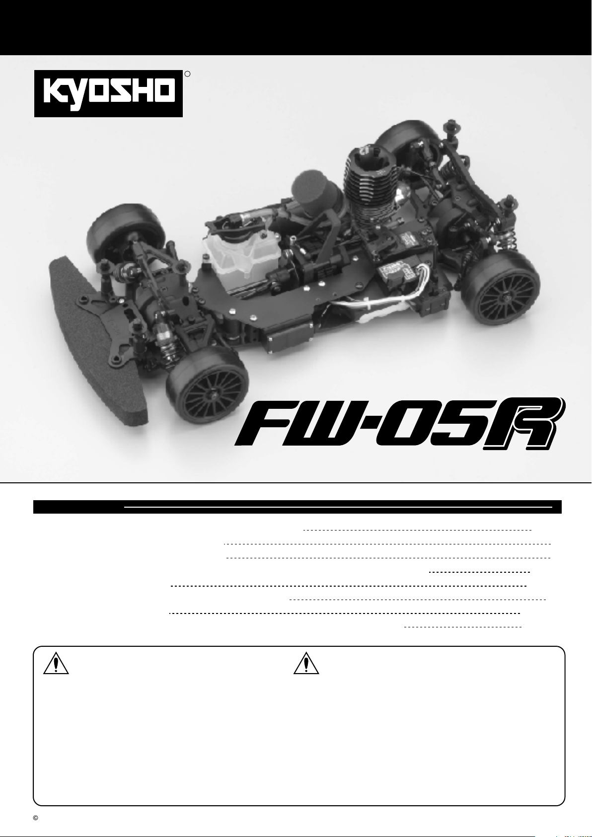
リヤサスペンション
Rear Suspension
17
4 x 8mm
Set Screw
3 x 15mm
Cap Screw
4mm
Flanged Nylon Nut
13
57
69
188
189
80
セットビス
キャップビス
フランジ付ナイロンナット
2 x 11mm
Pin
4.8mm
Ball Stud
9mm
Pillow Ball Nut
ホイルシャフト(リヤ)(銀)
Wheel Shaft (Rear) (Silver)
6x8x2mm
Aluminium Collar
6 x 12mm
Ball Bearing
ピン
ボールスタッド
ピロボールナット
アルミカラー
ベアリング
No.1, No.5, No.6
96
穴の広い方から入れる。
2
2
2
2
4
4
2
2
2
Insert from wider side.
99
57
< >
右側用
< >Right
100
4x8mm
下の穴を使用。
Use the holes
on the bottom.
Rのマーク
Marked ÒRÓ
98
57
97
96
188
101
5mm
81
段のある方が逆ネジ。
The side with the step
is a reverse screw.
98
x2
< >
左側用
< >Left
Lのマーク
Marked ÒLÓ
13
82
69
74
3x15mm
80
189
5.5mm
82
69
4mm
81
10 x 15mm
Ball Bearing
9mm
82
Pillow Ball
97
4 x 20mm
Adjustable Rod
98
6.8mm
Ball End
ベアリング
ピロボール
アジャスタブルロッド
ボールエンド
2
4
2
96
6.8mm
Flange Ball
4
82
座付ボール
六角レンチ(5mm)
Hex Wrench (5mm)
69
4
82
六角レンチ(2.5mm)
Hex Wrench (2.5mm)
1.8mm
Page 3
18ページ
Page18
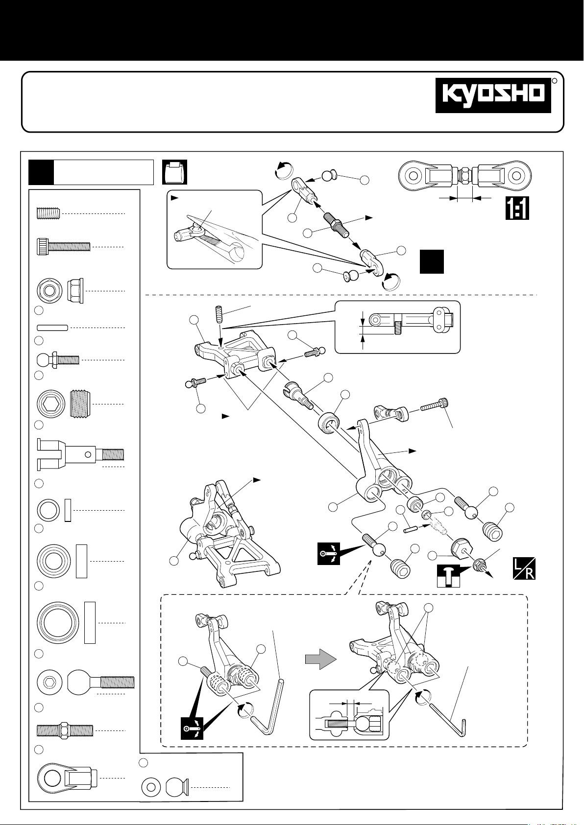
リヤサスペンション
Rear Suspension
18
3 x 15mm
Cap Screw
3 x 10mm
F/H Screw
187
スイングシャフト(リヤ)
Swing Shaft (Rear)
102
3 x 59mm
Shaft
28ページ
Page28
キャップビス
サラビス
シャフト
2
2
2
2
3x10mm
94
No.1, No.6
右側用
For Right
102
102
Hのマーク
Marked ÒHÓ
3x15mm
上の穴を使用。
Use the uppermost holes.
94
187
左側用
For Left
Hのマーク
Marked ÒHÓ
3x10mm
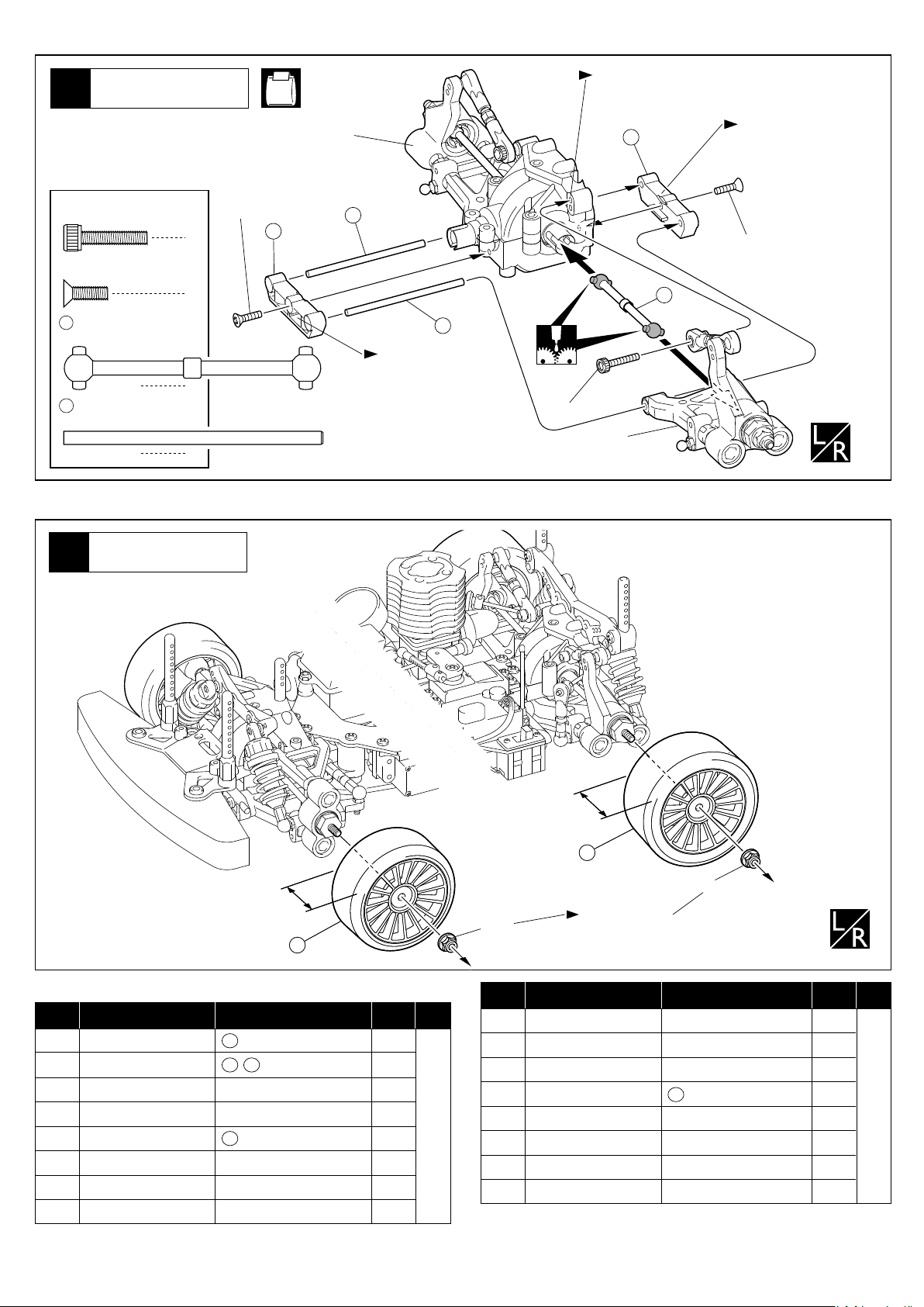
タイヤ
Wheels
41
26mm
26mm
フロント
< >
< >Front
スペアパーツ
品番
No.
スイングシャフト(ワイドタイヤ用)
VS033
Swing Shaft (Wide tyres)
ホイールシャフト(ワイドタイヤ用)
VZ081
Wheel Shaft (Wide tyres)
GRP 1/10ツーリングスポンジタイヤF30°(ホイール付)
622221
GRP 1/10 Touring Sponge Tire F30û (Wheel)
GRP 1/10ツーリングスポンジタイヤF32°(ホイール付)
622222
GRP 1/10 Touring Sponge Tire F32û (Wheel)
GRP 1/10ツーリングスポンジタイヤF35°(ホイール付)
622223
GRP 1/10 Touring Sponge Tire F35û (Wheel)
GRP 1/10ツーリングスポンジタイヤF37°(ホイール付)
622224
GRP 1/10 Touring Sponge Tire F37û (Wheel)
GRP 1/10ツーリングスポンジタイヤF40°(ホイール付)
622225
GRP 1/10 Touring Sponge Tire F40û (Wheel)
GRP 1/10ツーリングスポンジタイヤF42°(ホイール付)
622226
GRP 1/10 Touring Sponge Tire F42û (Wheel)
※製品改良のため、予告なく仕様を変更する場合があります。
*SPECIFICATIONS ARE SUBJECT TO BE CHANGED WITHOUT NOTICE.
© 2003 KYOSHO CORPORATION/禁無断転載複製
SPARE PARTS
パーツ名
Part Names
内容(キーNo.と入数)
187
x 2
188 189
ホイール接着成型済み
Pre-Trued & Glued
ホイール接着成型済み
Pre-Trued & Glued
190
x 2
ホイール接着成型済み
Pre-Trued & Glued
ホイール接着成型済み
Pre-Trued & Glued
ホイール接着成型済み
Pre-Trued & Glued
174
190
★FOR JAPANESE MARKET ONLY.
Quantity
x 2
★定価
600
700
1300
1300
1300
1300
1300
1300
★発送
手数料
200
(一律)
30mm
30mm
4mm
品番
No.
622227
622231
622232
622233
622234
622235
622236
622237
Part Names
GRP 1/10ツーリングスポンジタイヤF45°(ホイール付)
GRP 1/10 Touring Sponge Tire F45û (Wheel)
GRP 1/10ツーリングWスポンジタイヤR30°(ホイール付)
GRP 1/10 Touring W Sponge Tire R30û (Wheel)
GRP 1/10ツーリングWスポンジタイヤR32°(ホイール付)
GRP 1/10 Touring W Sponge Tire R32û (Wheel)
GRP 1/10ツーリングWスポンジタイヤR35°(ホイール付)
GRP 1/10 Touring W Sponge Tire R35û (Wheel)
GRP 1/10ツーリングWスポンジタイヤR37°(ホイール付)
GRP 1/10 Touring W Sponge Tire R37û (Wheel)
GRP 1/10ツーリングWスポンジタイヤR40°(ホイール付)
GRP 1/10 Touring W Sponge Tire R40û (Wheel)
GRP 1/10ツーリングWスポンジタイヤR42°(ホイール付)
GRP 1/10 Touring W Sponge Tire R42û (Wheel)
GRP 1/10ツーリングWスポンジタイヤR45°(ホイール付)
GRP 1/10 Touring W Sponge Tire R45û (Wheel)
< >
リヤ
< >
Rear
175
191
4mm
いったんはずして
取付け直します。
Remove when adjust.
パーツ名
京商株式会社
内容(キーNo.と入数)
ホイール接着成型済み
Pre-Trued & Glued
ホイール接着成型済み
Pre-Trued & Glued
ホイール接着成型済み
Pre-Trued & Glued
191
ホイール接着成型済み
Pre-Trued & Glued
ホイール接着成型済み
Pre-Trued & Glued
ホイール接着成型済み
Pre-Trued & Glued
ホイール接着成型済み
Pre-Trued & Glued
Quantity
x 2
〒243-0034 神奈川県厚木市船子153
★定価
1300
1300
1300
1300
1300
1300
1300
1300
★発送
手数料
200
(一律)
●ユ−ザ−相談室直通電話046-229-4115
お問い合わせは:月曜〜金曜(祝祭日を除く) 10:00〜18:00
61920307-1 PRINTED IN JAPAN
Page 4
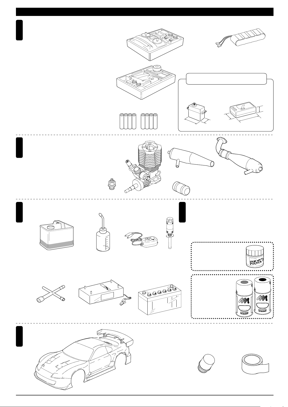
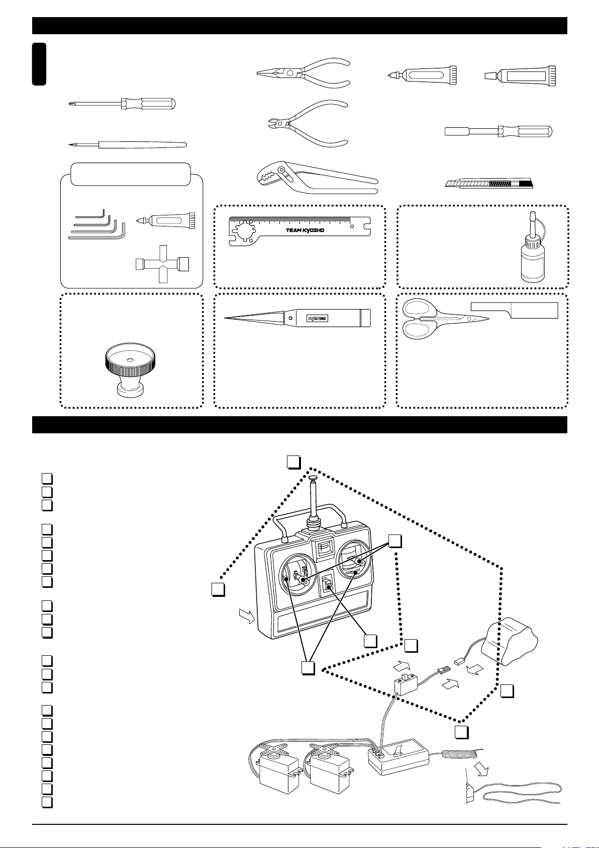
キットの他にそろえる物(1)REQUIRED FOR OPERATION (1)
2チャンネル2サーボ無線操縦機
1
(プロポ)
2ch radio control set with 2 servos.
●このキットには2チャンネル2サーボの
プロポが必要です。
●送信機にはスティックタイプとハンドル
タイプがありますが、お好みのタイプを
用意してください。
●リバーススイッチを使用する場合は、プ
ロポに付属の説明書を参考に設定してく
ださい。
●This kit requires a 2 channel radio con-
trol set with 2 servos.
●Because there are stick-type and wheeltype transmitters, use which ever fits
your convenience best.
●In case of using reverse switch, refer to
instruction manual included in the radio
set.
エンジンおよびマフラー
2
Engine & Muffler
●このキットには12クラスエンジ ンが必要
です。
※SGシャフト(パイロットシャ フト)仕
様で、スライドキャ ブ仕様のリコイル
スターターなしエン ジンのみ搭載でき
ます。
●This kit requires a .12 class engine.
*Only SG Shaft (Pilot Shaft) with Slide
Carburettor engine without pull starter
is available.
■スティックタイプ
2チャンネルプロポ
Stick-type
2ch radio set.
■ハンドルタイプ
2チャンネルプロポ
Wheel-type
2ch radio set.
■単3乾電池(送信機用)
AA-size Batteries (For Transmitter)
AAAA
AAAA
■12クラスカー用
エンジン
Engine for .12
class cars
■プラグ
Plug
■受信機用ニカドバッテリー
Ni-Cd Battery
※No.711626V600mAhRXニカドバッテリー
を必ず使用してください。
Only use No.71162 6V600mAh RX Ni-Cd Battery.
(Do not use other batteries.)
使用できるサーボ・受信機サイズ
Suitable servos & receiver
■サーボ
Servo
25〜29mm
38〜41mm
■マフラー
Muffler
■ジョイントパイプ
Joining Pipe
19〜20mm
No.39011 スーパーチューンドサイレンサーRセット(側方)
No. 39011 Super Tuned Silencer Set (Side)
No.VSW008 φ5.2マフラー&マニホールドセット(後方)
No. VSW008 ø5.2 Muffler & Manifold Set (Rear)
■受信機
Receiver
15〜17mm
36〜42.5mm
■
マフラーとマニホールド
Muffler and Manifold
燃料と始動用具
3
Required for engine starting:
■燃料 ■燃料ポンプ
Glow Fuel Fuel Pump
gine
Glow En
l
Fue
No.607004
RCモデルフュール
トルネード
Tornad fuel
No.96422
クイックフュールポンプ
Quick Fill Fuel Bottle
■プラグヒーター
Plug Heater
No.695142
DC急速充電器
DC Quick Charger
No.695141
■プラグレンチ ■スターター ■スターター用バッテリー
Plug Wrench Starter Battery
+
No.80312
ロッキングジグ/レンチ
Locking Jig & Wrench
No.39771
マルチスターターBOX
Multi Starter Box
その他
5
Other equipment required.
■ボディ
Body
4
スパークブースター
Spark Booster
−
塗料
Paint
●ボディの塗装には塗料が必要です。京商では、
モデル用塗料、スプレーを販売していますので
ご利用ください。
●For painting the body, use Kyosho paints
for models!
No.2230
ポリカカラー
POLYCA COLOR
No.76501〜76711
京商スプレーカラー
KYOSHO SPRAY COLOR
U
F
E
T
L
P
R
N
O
I
F
A
F
P
U
F
E
L
P
R
O
F
F
K
Y
S
O
S
P
R
A
Y
C
■エアフィルター ■グラステープ
Air Filter Tape
K
T
N
I
A
P
O
H
R
O
L
O
R
O
Y
H
S
O
S
P
R
O
R
L
A
O
Y
C
R
※200mm幅(KYOSHO製)の
ツーリングカーボディ
*KYOSHO Touring Car Body.
(200mm width)
2
Page 5
キットの他にそろえる物(2)REQUIRED FOR OPERATION (2)
組立てに必要な工具
Tools required
6
■+ドライバー(大、中、小)
Phillips Screwdriver (L.M.S)
■キリ
Awl
キットに入っている工具
■六角レンチ
Hex Wrench
■十字レンチ(小)
Cross Wrench (S)
No.TSW5
クラッチスプリングアジャストツール
Clutch Spring Adjust Tool
TOOLS INCLUDED
■グリス
Grease
Grease
■ラジオペンチ
Needle Nose Pliers
■ニッパー
Wire Cutters
■プライヤー
Pliers
50
No.80951B
フライホイールレンチ
Flywheel Wrench
■ネジロック剤
Screw Cement
ネジロック剤
■10mmボックスドライバー
Box Wrench
■カッターナイフ
Sharp Hobby Knife
mm
100
No.80951B
No.96154
KYOSHO スペシャルグルー
■ゴム系接着剤
Rubber Cement
ゴム系接着剤
KYOSHO Special Glue
瞬間接着剤
Instant Glue
KYOSHO
Special Glue
ナイフエッジリーマー
KNIFE EDGE REAMER
下穴加工が不要で、直接
1mm〜15mmの正確な穴
あけができる工具です。
プロポの準備 RADIO PREPARATION
●プロポを下の順番にしたがってセットします。
Set up the radio control system as indicated below.
1
単3乾電池をセットする(送信機)
アンテナをのばす(送信機)
2
充電した受信機用ニカドバッテ リーを
3
つなぐ。
アンテナをのばす(受信機)
4
トリムレバーを中央にセットする。
5
スイッチを入れる(送信機)
6
スイッチを入れる(受信機)
7
スティックを動かしてサーボが 動くか
8
確認する。
スイッチを切る(受信機)
9
スイッチを切る(送信機)
10
アンテナを縮める。
11
Install batteries. (Transmitter)
1
Extend the antenna. (Transmitter)
2
Connect the charged Ni-Cd battery to
3
the receiver.
Extend the antenna. (Receiver)
4
Center the trims.
5
Switch on. (Transmitter)
6
Switch on. (Receiver)
7
Make sure the servos are in command.
8
Switch off. (Receiver)
9
Switch off. (Transmitter)
10
Retract the antenna. (Transmitter)
11
1
START
No.695101
No need to pre-drill!
Drills neat 1mm to 15mm
holes directly!
2
5
6
ラウンドカッター&サンダー
ROUND CUTTER & SANDER
ボディのカット、仕上
げ用。曲線部分も楽に
作業ができます。
FINISH
8
7
No.1829
For trimming bodies!
Cutting along curved lines
never was so easy!
3
4
3
Page 6
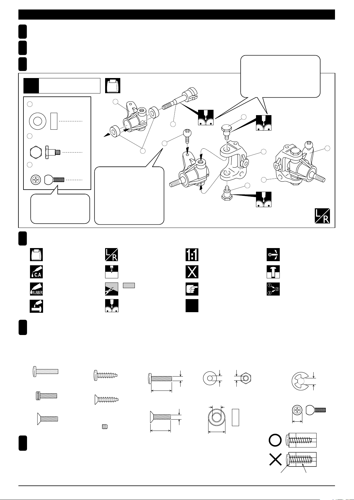
組立て前の注意 BEFORE YOU BEGIN
組立てる前に説明書を良く読んで、おおよその構造を理解してから組立てに入ってください。
1
Read through the manual before you begin, so you will have an overall idea of what to do.
キットの内容をお確かめください。万一不良、不足がありましたら、お買い求めの販売店にご相談いただくか、当社「ユーザー相談室」までご連絡ください。
2
Check all parts. If you find any defective or missing parts, contact your local dealer or our Kyosho Distributor.
説明書の見かた
3
How to read the instruction manual:
フロントサスペンション
Front Suspension
1
〔説明例 Example〕
No.4, No.5, No.6
説明書内では多くのマークが使用
されています。マークに注意して
組立てを進めてください。
This instruction manual uses several symbols. Please note them
during the entire assembly.
4
5 x 10mm メタル
Metal Bushing
キングピン
5
King Pin
5.8mm ピロボール(黒)
6
Pillow Ball (Black)
小物部品のキーNo.名前、
原寸図、使用数。
Key Number, Part Name,
True-to-scale Diagram,
Quantity Used
4
4
2
1
キット内の部品は、ビス類を除
いてキーNo.が付けられています。
スペアパーツを購入する時は
キーNo.を参照してください。
All parts except screws are identified
by key numbers. For purchasing
spare parts, find the key no. of the
part needed in the spare part list and
refer to the left column to look up the
corresponding order no.
説明書に使われているマーク
4
Symbols used throughout the instruction manual, comprise:
使用する袋詰。
Part bags used.
瞬間接着剤で接着する。
Apply instant glue
(CA glue, super glue).
ゴム系接着剤で接着する。
Apply rubber cement.
ネジロック剤を塗る。
Apply threadlocker
(screw cement).
左右同じように組立てる。
Assemble left and right sides
the same way.
2mmの穴をあける(例)。
Drill holes with the specified
2mm
diameter (here: 2mm).
をカットする。
Cut off shaded portion.
グリスを塗る。
Apply grease.
5
3
6
4
R
原寸図
True-to-scale diagram.
別購入品
Must be purchased separately!
注意して組立てる所。
Pay close attention here!
2セット組立てる(例)。
Assemble as many times as
x2
specified (here: twice).
7
L
8
5
可動するように組立てる。
Ensure smooth non-binding
movement while assembling.
仮止め。
Tentatively tighten.
番号の順に組立てる。
Assemble in the specified
order.
2
キットには、形や長さが違うビスや小物部品が多く入っています。説明書には原寸図がありますので確認してから
5
組立ててください。また、ビス類は多めに入っているものもありますので、予備としてお使いください。
This kit contains screws and hardware in different metric sizes and shapes. Before using them, check the screws on the true-to-scale diagrams
on the left side in each assembly step. Some screws are extras.
●ビスの種類 SCREWS
ビス
Screw
キャップビス
Cap Screw
サラビス
Flat Head (F/H) Screw
TPビス
Self-tapping (TP) Screw
TPサラビス
TP F/H Screw
セットビス
Set Screw
TPビスは、部品にネジを切りながらしめつけるビスです。しめこみが固い場合が
6
ありますが、部品が確実に固定されるまでしめこんでください。ただし、しめす
●小物部品のサイズ例 OTHER HARDWARE
3x12mmビス
Screw
12mm
3x12mmサラビス
F/H Screw
3mm
12mm
3mmワッシャー・ナット
Washer・Nut
3mm
5x10mmメタル・ベアリング
Metal Bushing・Bearing
3mm
5mm
10mm
E4Eリング
E-ring
5.8mmピロボール
Pillow Ball
5.8mm
Correct
ぎるとネジがきかなくなりますので、部品が変形するまでしめないでください。
Self-tapping (TP) screws cut threads into the parts when being tightened. Excessive force may
permanently damage parts when tightening TP screws. It is recommended to stop tightening when
the part is attached or when some resistance is felt after the threaded portion enters the plastic.
Wrong
しめすぎ
Overtightened.
ビスがきかない
The threads are stripped.
4
4mm
Page 7

ランナー付プラパーツ(1)
ARRANGEMENT OF PLASTIC PARTS ON RUNNERS (1)
18
18
No.3
No.5
14
No.4
52
15
49
6162
50 50
51
48
47
66
65
64
63
70
68
69 69
67
71
78 78
72 73
部分の部品は、使用しません。
Shaded Parts are not used.
74
76
74
76
77
75
77
5
Page 8
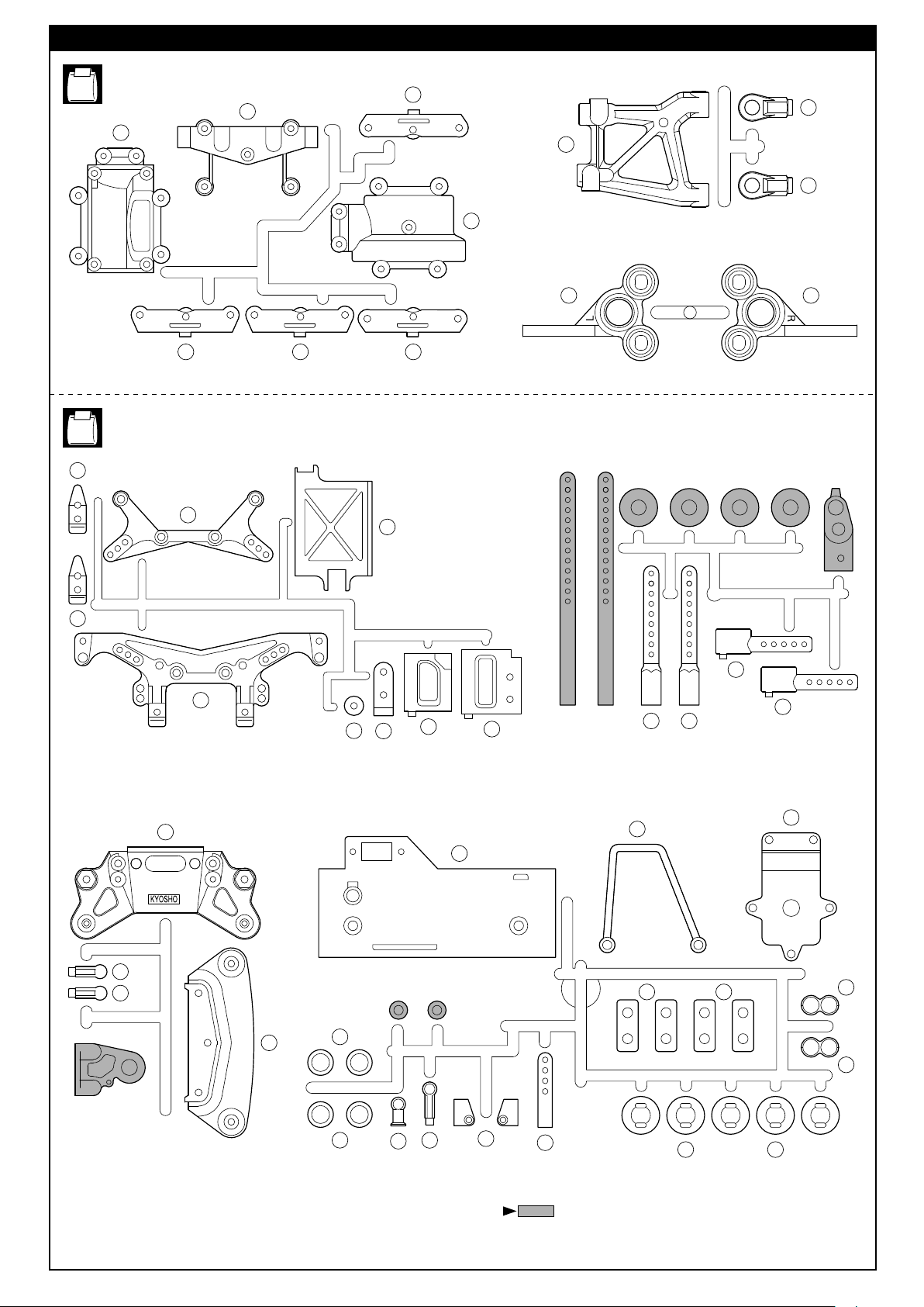
ランナー付プラパーツ(2)
ARRANGEMENT OF PLASTIC PARTS ON RUNNERS (2)
110
No.6
91
No.7
103
93
95
98
99
98
92
101 100
959494
105
110
118
118
117
104
116
132
109
106
108
126
107
120120
124
123 123
121
121
130
129
129
132
128
118
127
125
部分の部品は、使用しません。
Shaded Parts are not used.
131 131
6
Page 9
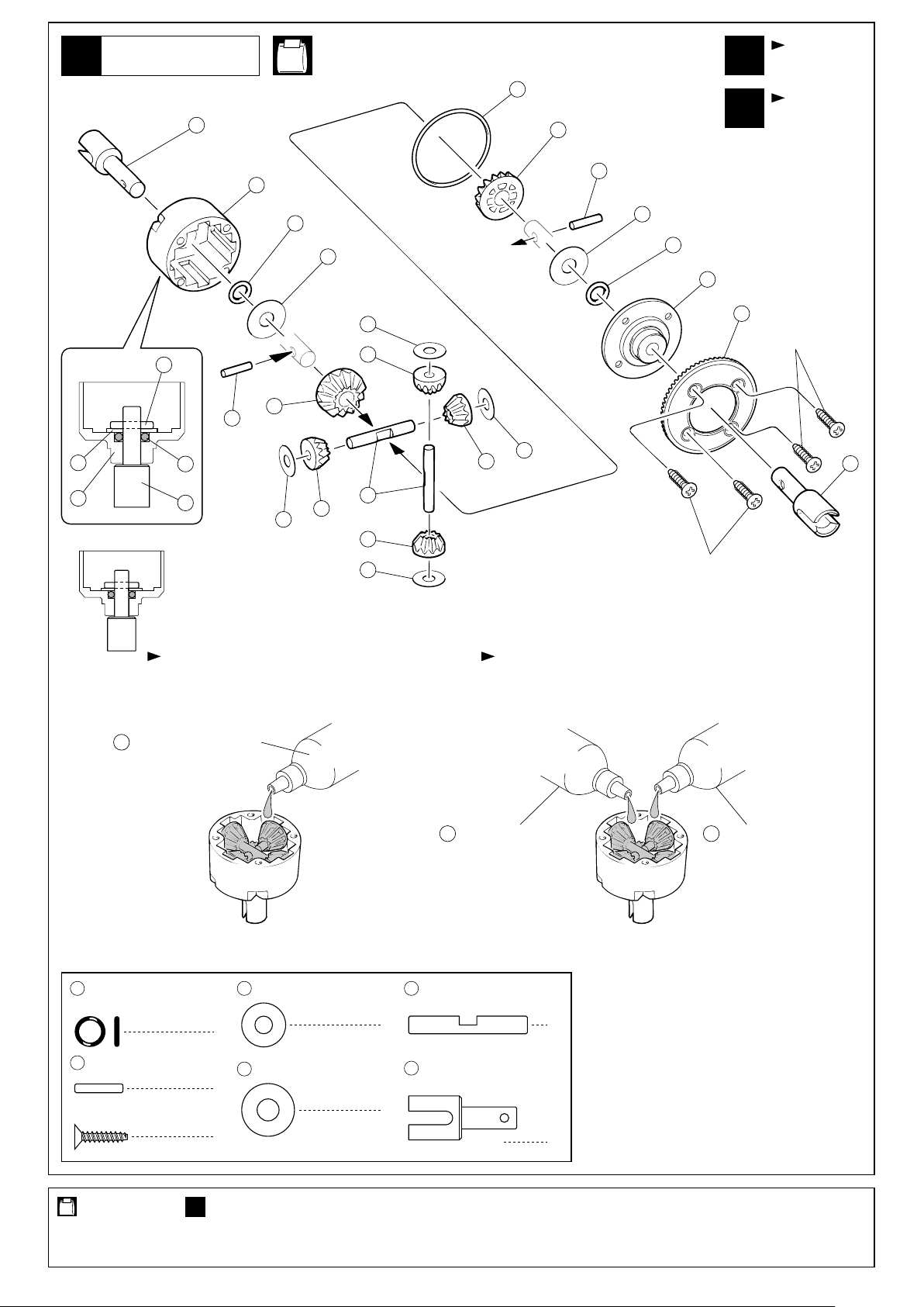
デフギヤ
Gear Differential
1
No.2, No.9
x1
5
8
7
x1
フロント用
For Front
リヤ用
For Rear
10
1
13
11
1
13
11
10
10
11
2
9
3
2.6x12mm
6
7
13
9
6
8
9
12
6
8
6
9
2.6x12mm
フロント用は、袋詰No.2に付属の
シリコンオイル(硬)を入れます。
Pour Silicon Oil (Hard) for front
included in the bag No.2.
184
高粘度シリコンオイル
Silicone Oil (Hard)
11
Oリング P5
O-ring P5
13
2 x 11mm
Pin
2.6 x 12mm
TP F/H Screw
ピン
TPサラビス
9 4 x 10mm
Shim
4
10
5 x 12mm
Shim
4
8
シム
シム
1244 x 27mm
Shaft
8
8
デフジョイント
Differential Joint
4
リヤ用は、袋詰No.9に付属のシリコンオイル(軟)
と(硬)を少量ずつ半々に入れてください。
Pour half of Silicon Oil (Hard) and half of
Silicon Oil (Soft) for rear included in the bag No.9.
184
高粘度シリコンオイル 低粘度シリコンオイル
Silicone Oil (Hard) Silicone Oil (Soft)
シャフト
4
176
使用する袋詰。
Part bags used.
1セット組立てる(例)。
x1
Assemble as many times as specified.
7
Page 10
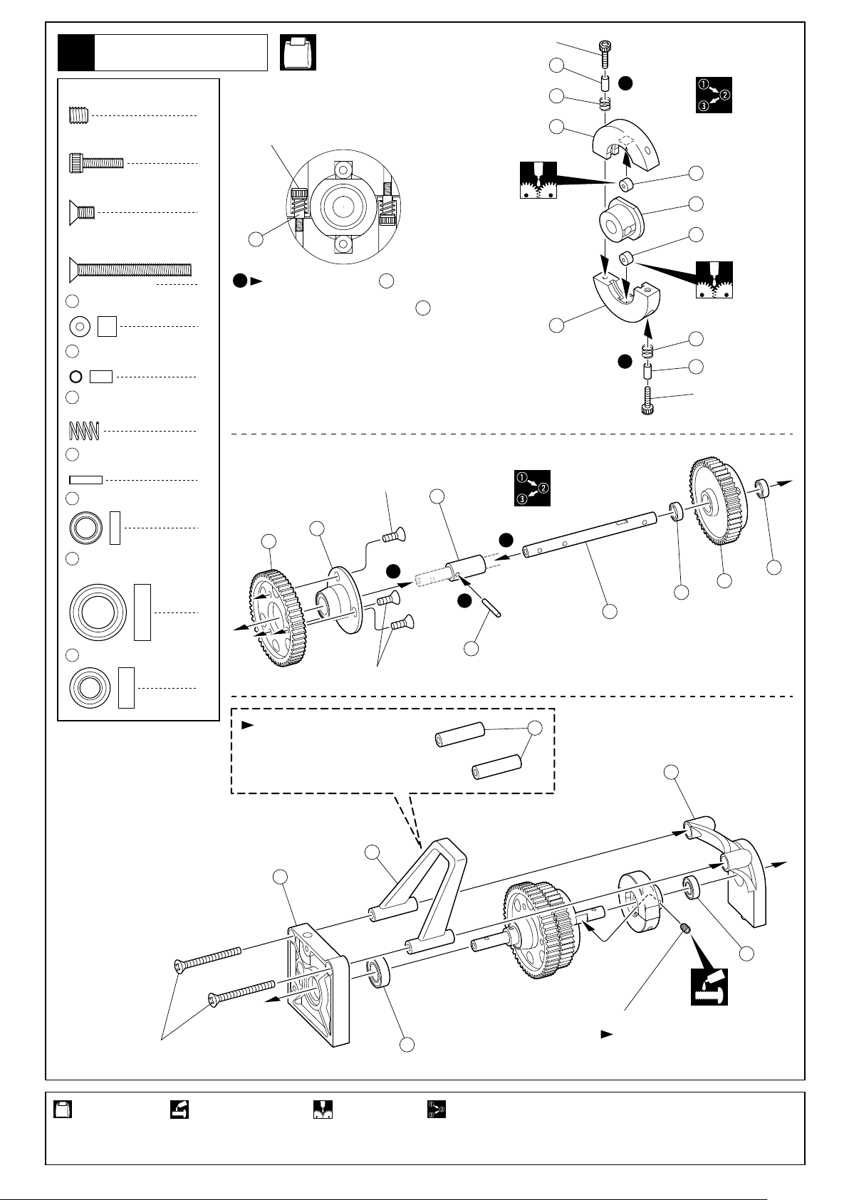
2スピードミッション
2 Speed Changer
2
4 x 4mm
Set Screw
2.6 x 10mm
Cap Screw
3 x 6mm
F/H Screw
3 x 30mm
F/H Screw
20
21
22
27
29
30
セットビス
キャップビス
サラビス
サラビス
5mm
Roller
2.6 x 3 x 5.5mm
Collar
2速スプリング
2 Speed Spring
2 x 8mm
Pin
5 x 8mm
Ball Bearing
8 x 14mm
Ball Bearing
ローラー
カラー
ピン
ベアリング
ベアリング
No.1, No.3, No.7
2.6x10mm
21
1
22
1
19
2.6x10mm
2
3
21
2
2
2
2.6mmキャップビスを カラーにあたる
までしめた所から1.5回転ゆるめる。
Tighten 2.6mm Cap Screw to Collar till the
screw stops, and unscrew 1.5 rounds, then
please set up according to the track condition.
21
21
19
1
2
2
1
2
23
24
3x6mm
26
1
3
1
2
28
20
185
20
22
21
2.6x10mm
29
25
29
31
5 x 10mm
Ball Bearing
ベアリング
3x30mm
27
1
ロールバーを使用しない場合。
If you do not want to install a
Roll Bar, use these parts instead.
3x6mm
18
15
124
14
31
4x4mm
30
平らな面にセットビスを固定する。
Firmly tighten the set screws onto
the flat spots.
使用する袋詰。 ネジロック剤を塗る。 グリスを塗る。
Part bags used. Apply threadlocker
(screw cement).
Apply grease.
8
番号の順に組立てる。
Assemble in the specified order.
Page 11
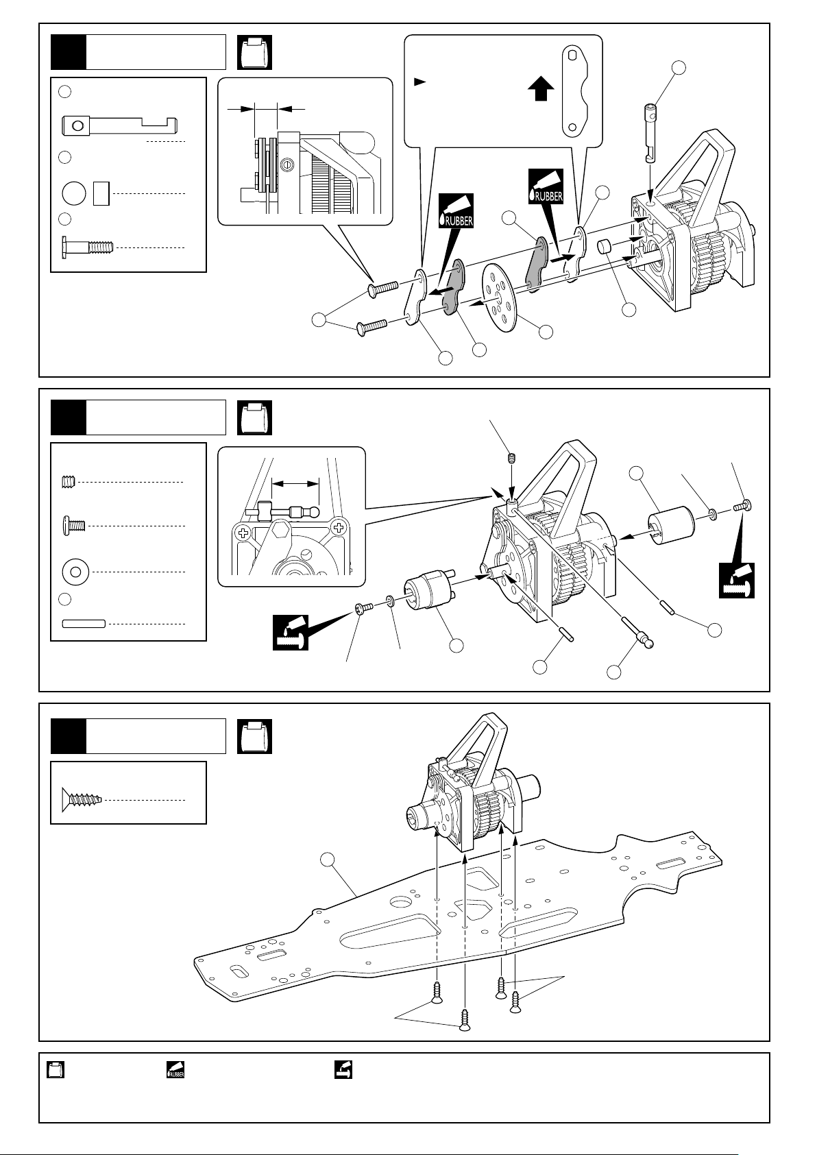
ブレーキ
Brake
3
ブレーキシャフト
32
Brake Shaft
ブレーキピストン
33
Brake Piston
No.3
向きに注意。
6.5mm
1
1
Note the direction.
上
Top
32
35
38212mm
4
3 x 3mm
Set Screw
2.6 x 4mm
Screw
2.6mm
Washer
13
ディスクプレートボルト
Disk Plate Bolt
センターギヤボックス
Center Gearbox
セットビス
ビス
ワッシャー
2 x 11mm
Pin
ピン
36
38
33
37
36
35
17
3x3mm
13
34
16
2.6mm
2.6x4mm
13
No.1, No.3
1
2
2
2
18mm
2.6mm
2.6x4mm
センターギヤボックス
Center Gearbox
5
3 x 10mm
TP F/H Screw
使用する袋詰。 ゴム系接着剤で接着する。
Part bags used. Apply rubber type glue.
TPサラビス
4
No.1
39
3x10mm
3x10mm
ネジロック剤を塗る。
Apply threadlocker (screw cement).
9
Page 12
ステアリング
Steering
6
40
ステアリングピン
Steering Pin
41
3 x 6mm
Metal Bushing
44
サーボセイバーナット
Servo Saver Nut
メタル
No.4
43
47
2
40
41
2
42
40
49
24.5mm
41
前
Front
向きに注意。
Note the direction.
前
Front
No.1, No.4, No.9
0mm
45
サーボセイバースプリング
Servo Saver Spring
ステアリング
Steering
7
1
1
3x15mm
112
112
x2 x1
54
48
45
44
上
Top
14mm
53
54
3 x 8mm
F/H Screw
3 x 15mm
Set Screw
3mm
Nylon Nut
53
54
使用する袋詰。
Part bags used.
2セット組立てる(例)。
x2
Assemble as many times as specified.
サラビス
セットビス
ナイロンナット
3 x 30mm
Rod
5.8mm
Ball End
ロッド
ボールエンド
1
2
2
1
2
ネジロック剤を塗る。
Apply threadlocker (screw cement).
55
3 x 7 x 3mm
Collar
5.8mm
56
Flange Ball
57
4.8mm
Ball Stud
112
4.8mm
Ball End (Medium)
カラー
座付ボール
ボールスタッド
ボールエンド(中)
可動するように組立てる。
Ensure smooth, non-binding movement when assembling.
3x8mm
2
57
1
2
4
55
3mm
57
55
3mm
56
原寸図。
True-to-scale diagram.
注意して組立てる所。
Pay close attention here!
10
Page 13
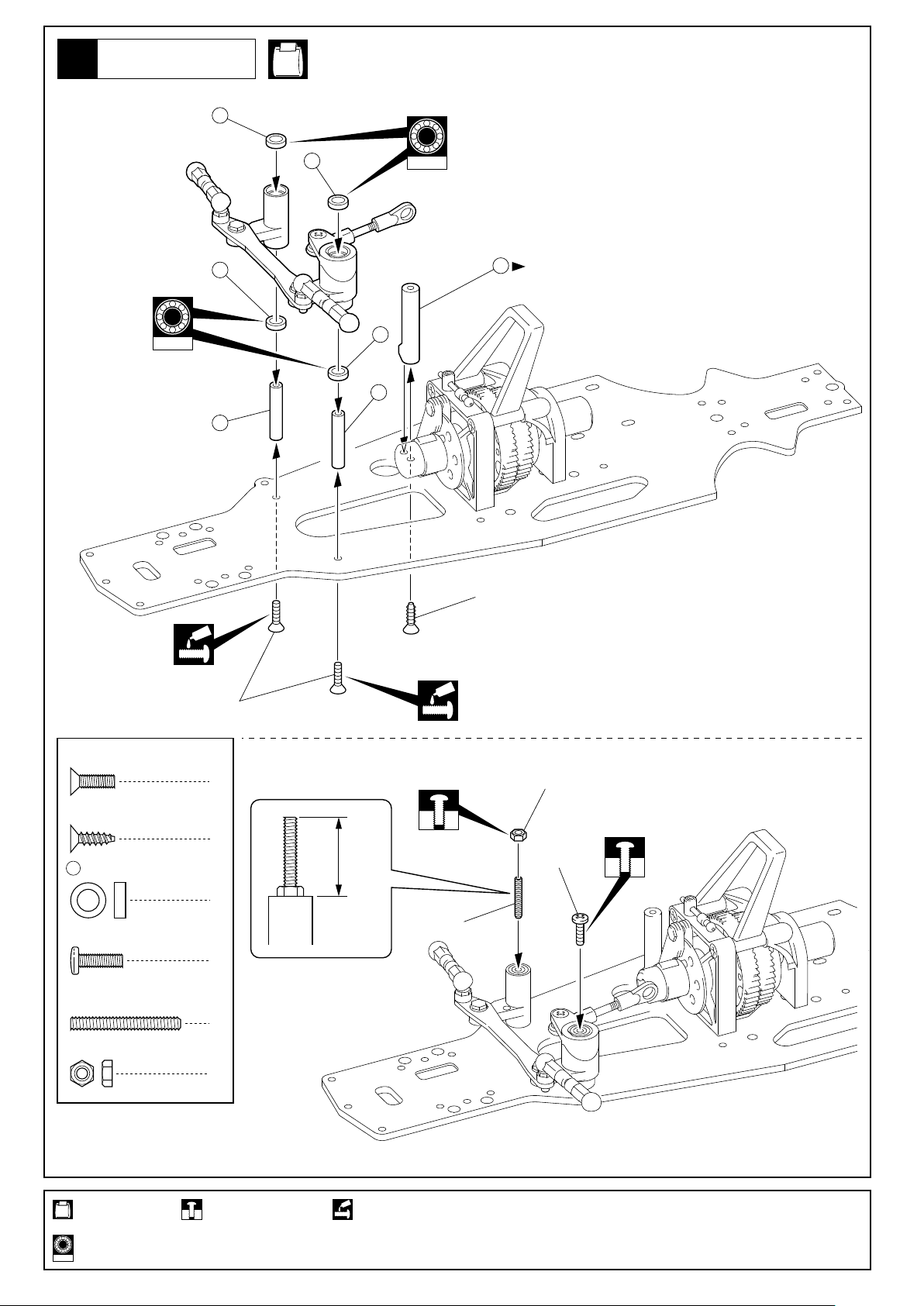
ステアリング
Steering
8
No.1, No.4
50
BRG002
50
46
50
46
50
BRG002
51
向きに注意。
Note the direction.
3x10mm(TP F/H)
3x10mm(F/H)
3 x 10mm
F/H Screw
3 x 10mm
TP F/H Screw
50
5 x 8 x 2.5mm
Plastic Bushing
3 x 10mm
Screw
3 x 25mm
Set Screw
3mm
Nut
サラビス
TPサラビス
プラメタル
ビス
セットビス
ナット
2
1
18mm
4
3x25mm
1
1
1
3mm
3x10mm
使用する袋詰。
Part bags used.
オプションのベアリングの品番。(例 : No.BRG002)
Ball bearings are optional ! (with optional part no.)
BRG002
仮止め。
Temporarily tighten.
ネジロック剤を塗る。
Apply threadlocker (screw cement).
11
Page 14

フロントギヤボックス
Front Gearbox
9
13
2 x 11mm
Pin
29
5 x 8mm
Ball Bearing
31
5 x 10mm
Ball Bearing
59
12 x 18mm
Ball Bearing
60
12 x 15 x 0.1mm
Shim
192
12 x 15 x 0.2mm
Shim
ピン
ベアリング
ベアリング
ベアリング
シム
シム
No.5
193
59
192
枚数を変えて、バック
ラッシュを調整する。
1
1
1
2
60
Adjust the backlash
with the shims.
31
13
4
60
枚数を変えて、バックラッシュ
を調整する。
192
Adjust the backlash with the shims.
29
58
59
1
61
193
5 x 8 x 0.5mm
4
Shim
シム
1
フロントギヤボックス
Front Gearbox
10
3 x 6mm
Cap Screw
3 x 12mm
Cap Screw
3 x 20mm
Cap Screw
3 x 10mm
TP Screw
3 x 10mm
TP F/H Screw
4 x 8mm
Set Screw
キャップビス
キャップビス
キャップビス
TPビス
TPサラビス
セットビス
1
2
2
1
2
2
4x8mm
3x20mm
3x6mm
63
3x12mm
No.1, No.5, No.7
125
3x20mm
3x10mm(TP)
103
62
3x10mm(TP F/H)
1mm
使用する袋詰。
Part bags used.
12
グリスを塗る。
Apply grease.
Page 15

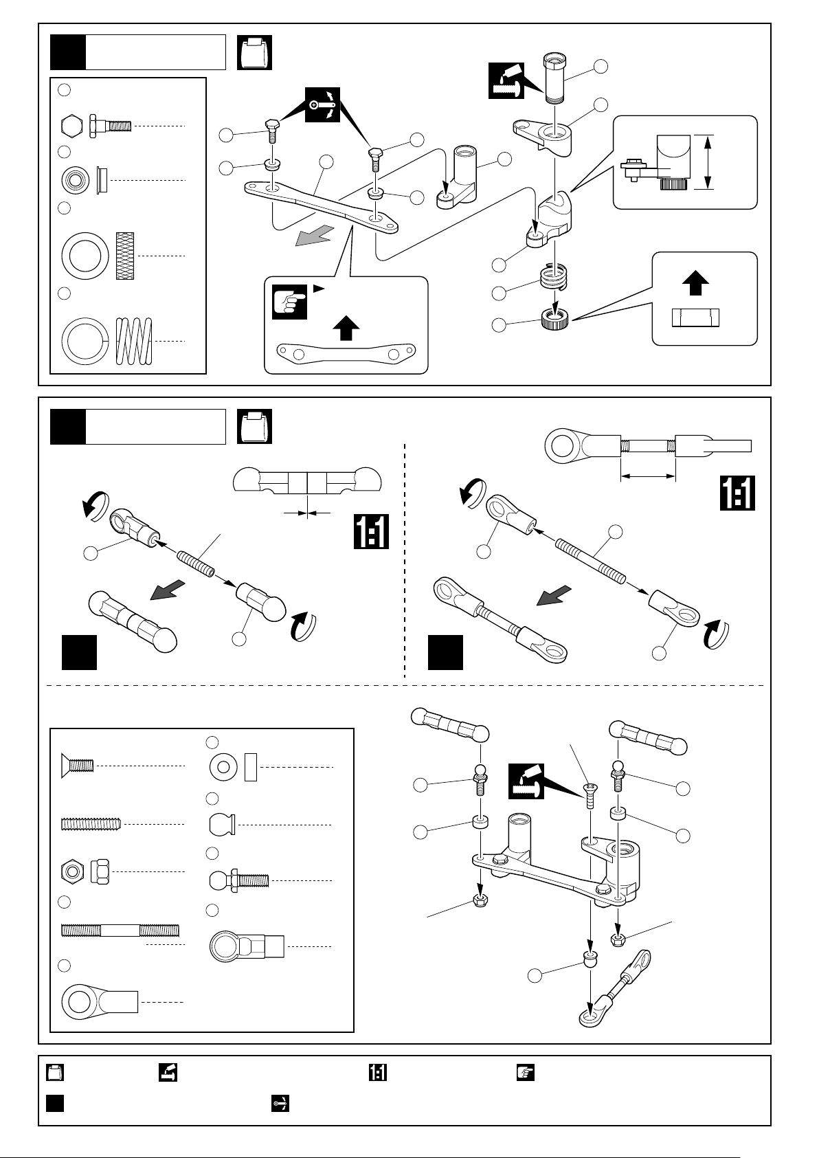
フロントサスペンション
Front Suspension
11
No.1, No.5
7mm
3x3mm
83
3 x 3mm
Set Screw
3 x 12mm
Screw
4mm
Flanged Nylon Nut
13
57
69
セットビス
ビス
フランジ付ナイロンナット
2 x 11mm
Pin
4.8mm
Ball Stud
9mm
Pillow Ball Nut
ピン
ボールスタッド
ピロボールナット
2
2
2
2
4
4
85
3x12mm
< >
右側用
< >Right
6.5mm
64
70
66
72
57
67
68
79
Rのマーク
Marked ÒRÓ
73
81
57
82
< >
左側用
< >Left
13
69
Lのマーク
Marked ÒLÓ
82
69
80
4mm
74
83
3 x 57mm
Shaft
79
ホイールシャフト
Wheel Shaft
80
6 x 12mm
Ball Bearing
81
10 x 15mm
Ball Bearing
9mm
82
Pillow Ball
シャフト
ベアリング
ベアリング
ピロボール
65
2
2
2
69
82
2
4
84
六角レンチ(5mm)
Hex Wrench (5mm)
4.5mm
82
六角レンチ(2.5mm)
Hex Wrench (2.5mm)
4mm
使用する袋詰。
Part bags used.
可動するように組立てる。
Ensure smooth, non-binding movement when assembling.
仮止め。
Temporarily tighten.
左右同じように組立てる。
Assemble left and right sides the same way.
13
Page 16

フロントサスペンション
Front Suspension
12
No.1, No.5
右側用
For Right
左側用
For Left
3x10mm
3 x 10mm
TP F/H Screw
E2.5
E-ring
13
TPサラビス
Eリング
フロントサスペンション
Front Suspension
No.1, No.3
86
2
2
E2.5
90
89
3 x 15mm
TP F/H Screw
89
Oリング P3(黒)
O-ring P3 (Black)
使用する袋詰。
Part bags used.
TPサラビス
14
4
1
仮止め。
Temporarily tighten.
3x15mm
仮止めしていたビスもしめる。
Securely tighten the screws that were
only temporarily installed earlier.
3x15mm
左右同じように組立てる。
Assemble left and right sides the same way.
Page 17

フロントサスペンション
Front Suspension
14
No.1, No.5
3 x 5mm
Set Screw
E2.5
E-ring
87
セットビス
Eリング
3 x 37mm
Shaft
シャフト
88
スイングシャフト
Swing Shaft
2
2
89
2
1
Oリング P3(黒)
O-ring P3 (Black)
89
2
2
2
3x5mm
3x5mm
87
88
E2.5
3
87
2
3
88
1
89
E2.5
71
71
使用する袋詰。
Part bags used.
グリスを塗る。
Apply grease.
番号の順に組立てる。
Assemble in the specified order.
15
Page 18

15
バンパー
Bumper
No.1, No.7
120
3 x 10mm
TP Screw
3 x 10mm
F/H Screw
3mm
Nylon Nut
TPビス
サラビス
ナイロンナット
3mm
116
3x10mm(F/H)
3x10mm
6
120
117
3
3
3x10mm
3x10mm
119
3x10mm
リヤギヤボックス
Rear Gearbox
16
3 x 6mm
Cap Screw
3 x 15mm
Cap Screw
13
29
31
59
キャップビス
キャップビス
2 x 11mm
Pin
5 x 8mm
Ball Bearing
5 x 10mm
Ball Bearing
12 x 18mm
Ball Bearing
ピン
ベアリング
ベアリング
ベアリング
No.1, No.6
59
60
枚数を変えて、バックラッシュ
を調整する。
192
1
4
13
1
1
58
1
2
29
31
193
4
Adjust the backlash with the shims.
192
枚数を変えて、
バックラッシュ
60
を調整する。
Adjust the backlash
with the shims.
59
91
3x15mm
3x15mm
3x6mm
93
92
60
12 x 15 x 0.1mm
Shim
使用する袋詰。
Part bags used.
16
192
シム シム シム
グリスを塗る。
Apply grease.
12 x 15 x 0.2mm
Shim
1
193
5 x 8 x 0.5mm
Shim
4
1
Page 19

リヤサスペンション
Rear Suspension
17
4 x 8mm
Set Screw
3 x 15mm
Cap Screw
4mm
Flanged Nylon Nut
13
57
69
79
セットビス
キャップビス
フランジ付ナイロンナット
2 x 11mm
Pin
4.8mm
Ball Stud
9mm
Pillow Ball Nut
ホイールシャフト
Wheel Shaft
ピン
ボールスタッド
ピロボールナット
No.1, No.5, No.6
96
穴の広い方から入れる。
Insert from wider side.
98
段のある方が逆ネジ。
The side with the step
is a reverse screw.
7mm
97
2
98
96
2
x2
2
99
2
4
57
4
4x8mm
下の穴を使用。
Use the holes
on the bottom.
57
79
5mm
81
< >
左側用
< >Left
Lのマーク
Marked “L”
3x15mm
80
6 x 12mm
Ball Bearing
81
10 x 15mm
Ball Bearing
9mm
82
Pillow Ball
96
6.8mm
Flange Ball
97
4 x 20mm
Adjustable Rod
98
6.8mm
Ball End
ベアリング
ベアリング
ピロボール
座付ボール
アジャスタブルロッド
ボールエンド
2
2
2
4
4
2
< >
右側用
< >Right
100
82
Rのマーク
Marked “R”
六角レンチ(5mm)
Hex Wrench (5mm)
69
101
3.8mm
82
13
69
80
74
82
六角レンチ(2.5mm)
Hex Wrench (2.5mm)
82
69
4mm
4
使用する袋詰。
Part bags used.
可動するように組立てる。
Ensure smooth, non-binding movement when assembling.
仮止め。
Temporarily tighten.
原寸図。
True-to-scale diagram.
左右同じように組立てる。
Assemble left and right sides the same way.
2セット組立てる(例)。
x2
Assemble as many times as specified.
17
Page 20

リヤサスペンション
Rear Suspension
18
No.1, No.6
上の穴を使用。
Use the uppermost holes.
3 x 15mm
Cap Screw
3 x 10mm
F/H Screw
88
スイングシャフト
Swing Shaft
102
3 x 59mm
Shaft
キャップビス
サラビス
シャフト
リヤダンパーステー
Rear Shock Stay
19
2
2
2
2
94
3x10mm
右側用
For Right
102
No.1, No.7
Hのマーク
Marked “H”
102
3x15mm
左側用
For Left
94
Hのマーク
Marked “H”
3x10mm
88
3 x 10mm
TP F/H Screw
3 x 10mm
TP Screw
TPサラビス
TPビス
リヤサスペンション
Rear Suspension
20
3 x 10mm
TP F/H Screw
90
センターシャフト
Center Shaft
TPサラビス
2
2
3x10mm(TP)
104
3x10mm(TP F/H)
3x10mm(TP)
No.1, No.3
8
1
90
使用する袋詰。
Part bags used.
18
グリスを塗る。
Apply grease.
3x10mm
3x10mm 3x10mm
左右同じように組立てる。
Assemble left and right sides the same way.
Page 21

リヤスタビライザー
Rear Stabilizer
21
No.1, No.6, No.9
3 x 3mm
Set Screw
3 x 8mm
54
111
113
114
セットビス
座付キャップビス
Flanged Cap Screw
5.8mm
ボールエンド
Ball End
4.8mm
ボールエンド(短)
Ball End (Short)
3 x 15mm
Adjustable Rod
5.8mm
Ball Stopper
アジャスタブルロッド
ボールストッパー
114
2
54
113
2
段のある方
が逆ネジ。
The side with
the step is a
reverse screw.
111
5mm
x2
2
2
2
2
3mm
3x3mm
リヤボディマウント
Rear Body Mounts
22
3 x 10mm
TP Screw
TPビス
115
3x8mm
3x10mm
No.1, No.7
2
3x10mm
121
使用する袋詰。
Part bags used.
2セット組立てる(例)。
x2
Assemble as many times as specified.
可動するように組立てる。
Ensure smooth, non-binding movement when assembling.
121
左右同じように組立てる。
Assemble left and right sides the same way.
原寸図。
True-to-scale diagram.
19
Page 22

ステアリングサーボ
Steering Servo
23
No.1, No.4, No.5, No.7
3 x 8mm
Screw
3 x 10mm
TP Screw
3 x 15mm
TP Screw
56
ビス
TPビス
TPビス
5.8mm
座付ボール
Flange Ball
< > FUTABA
SANWA
1
4
< / S9451 >FUTABA
106
4
< >
1
JR
77
(1mm)
106
< >
(1mm)
77
< >
KO
(1mm)
77
(2mm)
123
106
106
105
106
122
両面テープ
Double-sided Tape
向きに注意。
Note the direction.
3x10mm
3x15mm
使用するサーボに合わせる。
Set up according the
servo you use.
3 x 10mm
TP Screw
3 x 15mm
TP Screw
TPビス
TPビス
4
ステアリングサーボ
4
Steering Servo
107
約18mm
approx. 18mm
サーボ付属のゴムグロメット
を使用する。
Be sure to use the rubber
bushings included with
3x10mm
3x15mm
3x8mm
the servos.
サーボホーン
Servo Horn
56
約10°の所をニュートラル
位置に合わせる。
Neutral position must be at a
10 degree angle as shown in
the drawing.
10¡
使用する袋詰。
Part bags used.
20
別購入品。
Must be purchased separately!
Page 23

サーボセイバー
Servo Saver
24
3x10mm
No.1, No.5, No.7
3x10mm
使用するサーボに合わせる。
Set up according the
servo you use.
3 x 10mm
TP Screw
TPビス
4
134
3x10mm
77 78
123
3x10mm
3x15mm
108
130
77 78
76
3 x 15mm
TP Screw
スロットルサーボ
Throttle Control Servo
123
上の寸法になるように、
77 78
123
,,を調整する。
Use parts , and to
achieve the dimensions shown
in the drawing.
77 78
3 x 10mm
TP Screw
3 x 15mm
TP Screw
TPビス
23~24.5mm
123
TPビス
TPビス
77 78
4
123
10
4
バッテリー
Battery
25
グラステープ等で巻く。
Fix with Glass Tape, etc.
No.1, No.7
126
122
両面テープ
Double-sided Tape
バッテリー
Battery
使用できるバッテリー No.71162 6V600mAh ニカドバッテリー
3 x 8mm
TP Screw
TPビス
No.71162 6V600mAh RX Ni-cd BatterySuitable Battery
3x8mm
2
使用する袋詰。
Part bags used.
別購入品。
Must be purchased separately!
21
Page 24

受信機
Receiver
26
プロポの説明書を参考に、
コネクターを接続する。
Connect as per radio
instruction manual.
コードが路面に接触しないように、
ストラップで固定する。
163
Use straps to prevent the cords
from ever touching the ground.
No.7
受信機
Receiver
122
両面テープ
Double-sided Tape
163
アンテナコード
を通す。
Thread antenna
cord through.
136
135
アンテナ
Antenna
スイッチ
Switch
スイッチ
Switch
メカプレート / 燃料タンク
Radio Plate / Fuel Tank
27
No.1, No.4, No.5, No.7
3x12mm
で、仮止めしていたもの。8
Use the screws that were
tightened temporarily
8
in Step .
3x12mm
3x10mm(TP)
3mm
3 x 10mm
TP Screw
3 x 12mm
TP Screw
3 x 10mm
TP F/H Screw
使用する袋詰。
Part bags used.
TPビス ナイロンナット
TPビス
TPサラビス
22
3x10mm(TP F/H)
3mm
Nylon Nut
1
89
Oリング P3(黒)
O-ring P3 (Black)
4
2
Must be purchased separately! Ensure smooth, non-binding movement when assembling.
1
2
可動するように組立てる。別購入品。
186
89
52
89
Page 25

エンジン
Engine
28
7 x 11mm
140
Washer
No.8
ワッシャー
1
140
このキットは、SGシャフト(パイロット
シャフト)仕様専用です。
For Side Exhaust, SG shaft (Pilot shaft) type.
1.5mm
146
147
エンジン
Engine
29
3 x 10mm
Cap Screw
3 x 12mm
Cap Screw
3 x 15mm
Cap Screw
キャップビス
キャップビス
キャップビス
155
ベルガイドワッシャー
Bell Guide Washer
4
1
31
5 x 10 x 4mm
Ball Bearing
1
145
No.1, No.8
パイロットナットをしめた時ここに
隙間ができない時は、付属のワッシ
ャーを入れる。
In case of no space as shown, insert
the washer included in the kit.
142
143
144
3x10mm (Cap)
燃料チューブ取付ニッ
プルを前方に向ける。
Position the nipple
1
forward as shown
ベアリング
in the drawing.
2
141
137
139
3Dウエイトは、 フライホイール
142 137
のピンの間に置く。
Place the 3D Weights between the
pins of the flywheel .
142
137
142
3x10mm (Cap)
エンジンアッセンブリー
Engine Assembly
キャブレターリンケージ
部を下図の様に取付ける。
Match the nipple direction for
the carburetor linkage to the
angle shown in the drawing.
40°
137
0.5mm
153 154
155
使用する袋詰。
Part bags used.
154
ここのすきまが0.5mm(別紙
セッティングシート参照)に
なるように、 5x0.1mmシム
154
と 5x0.5mmシムで調節する。
Adjust 5x0.1mm, 5x0.5mm
so that this space to be 0.5mm
(Refer to the Setting Sheet).
153
153
150
154
31
149
148
151
31
152
153
4.8mm
の向きに注意。
152
Note the direction.
3x12mm
3x15mm
使用するエンジンに合わせる。
Select according to the engine you use.
別購入品。 ネジロック剤を塗る。
Must be purchased separately! Apply threadlocker (screw cement).
5.0mm
エンジン側
Engine
148
148
エンジンによっては、
148
の内側を少し削る。
Cut off shaded portion
if it is needed.
148
23
Page 26

エンジン
Engine
30
後方排気の場合は、No.VSW009を、
サイド排気の場合は、No.39013の
マニホールドを使用してください。
For a rear exhaust engine, use Part
No. VSW009. For a side exhaust
engine, use Part No. 39013.
No.1
エンジンアッセンブリー
Engine Assembly
紙1枚分のすき間を
つくって固定する。
Tighten the screws
with one sheet of
paper inserted between
both gears.
3 x 8mm
Screw
ビス
マフラー
Muffler
31
3x8mm
4
3x8mm
No.1, No.7, No.8
3x3mm
109
162
エアークリーナー
156
Air Cleaner
3 x 3mm
Set Screw
3 x 10mm
TP F/H Screw
セットビス
TPサラビス
使用する袋詰。
Part bags used.
24
1
1
別購入品。
Must be purchased separately!
3x10mm
使用するマフラーに
合わせて曲げる。
Bend the wire to adjust
the muffler.
Page 27

スロットルリンケージ
Throttle Linkages
32
No.1, No.5, No.7
向きに注意。
Note the direction.
128
160
2x10mm
158
2mm
3x3mm
約15mm
approx. 15mm
サーボホーン
Servo Horn
約15mm
approx. 15mm
3 x 3mm
Set Screw
2mm
Nylon Nut
2 x 10mm
Screw
160
161
セットビス
ナイロンナット
ビス
スロットルブレーキスプリング
Throttle Brake Spring
2mm
Stopper
ストッパー
127
2mm
161
159
127
157
118
1
2
2
1
1
プロポに付属
Come with radio.
2x10mm
75
燃料チューブを15mmに
カットして使用。
Cut off the fuel tube 15mm.
燃料チューブ
Fuel Tube
33
No.7
157
燃料チューブをエンジンと
マフラーに合わせてカットする。
Cut the fuel tubing to the proper
length, as shown in the drawing.
使用する袋詰。
Part bags used.
10 20mm0
129
別購入品。 可動するように組立てる。
Must be purchased separately! Ensure smooth, non-binding movement when assembling.
25
Page 28

フロントダンパー
Front Shock
34
111
4.8mm
ボールエンド(短)
Ball End (Short)
2.6mm
ナイロンナット
Nylon Nut
168
ダンパーピストン
Shock Piston
2.6mm
ワッシャー
Washer
2
2
2
2
171
ダンパーカラー(A)
Shock Collar (A)
172
Cリング
170
Oリング
O-ring
2
C-ring
2
4
No.9
166
170
171
172
2.6mm
168
2.6mm
167
174
173
111
169
176
低粘度
シリコン
オイル
Silicone
(Soft)
175
164
x2
フロントダンパー
Front Shock
35
No.9
リヤダンパー
Rear Shock
36
112
4.8mm
Ball End (Medium)
2.6mm
ナイロンナット
Nylon Nut
168
ダンパーピストン
Shock Piston
2.6mm
ワッシャー
Washer
ボールエンド(中)
171
ダンパーカラー(A)
Shock Collar (A)
2
172
Cリング
2
170
Oリング
O-ring
2
165
177
フロント用(短)
For Front (Short)
No.9
2.6mm
2
2
C-ring
2
166
170
171
168
2.6mm
167
174
173
169
112
4
172
176
x2
175
164
低粘度
シリコン
オイル
Silicone
(Soft)
x2
リヤダンパー
Rear Shock
37
使用する袋詰。
Part bags used.
26
No.9
リヤ用(長)
For Rear (Long)
2セット組立てる(例)。
x2
Assemble as many times as specified.
165
178
x2
Page 29

フロントダンパー
Front Shock
38
No.1, No.9
3 x 12mm
Set Screw
179
3 x 6 x 2mm
Collar
5.8mm
56
Flange Ball
セットビス
カラー
座付ボール
2
2
2
3x12mm
179
56
179
56
3x12mm
リヤダンパー
Rear Shock
39
3 x 12mm
Set Screw
3 x 6 x 2mm
179
Collar
5.8mm
56
Flange Ball
セットビス
カラー
座付ボール
フロントダンパー
Front Shock
2
2
2
179
56
No.1, No.9
3x12mm
179
3x12mm
使用する袋詰。
Part bags used.
56
リヤダンパー
Rear Shock
ネジロック剤を塗る。
Apply threadlocker (screw cement).
27
Page 30
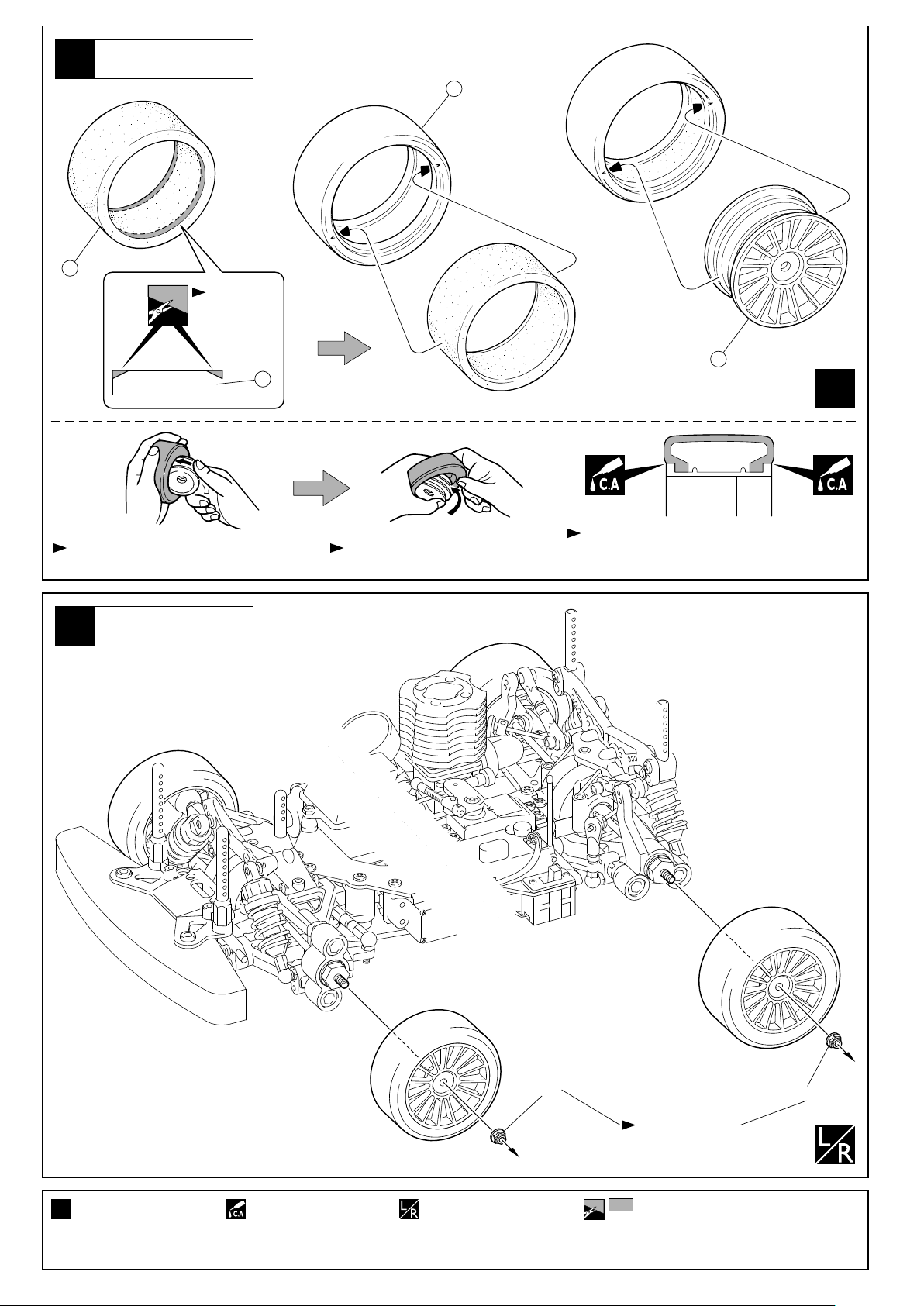
40
180
タイヤ
Wheels
181
カットする。
Cut off.
182
180
x4
ホイールを回しながら半分くらいタイヤにいれる。 タイヤを強くひっぱりホイールを押しこむ。
Fit wheels inside tyres as shown.
タイヤ
Wheels
41
Twist the tyre onto the wheel.
ピッタリはめてからタイヤとホイールのつなぎ目に
瞬間接着剤を流し接着する。
After fitting wheels to tyres, apply instant glue as shown.
リヤ
< >
< >Rear
4セット組立てる(例)。
x4
Assemble as many
times as specified.
28
フロント
< >
< >Front
瞬間接着剤で接着する。
Apply instant glue
(CA glue, super glue).
4mm
左右同じように組立てる。
Assemble left and right
sides the same way.
4mm
いったんはずして
取付け直します。
Remove when adjust.
をカットする。
Cut off shaded portion.
Page 31

42
ボディ
Body Shell
No.1, No.7
183
2 x 10mm
Screw
183
ボディピン
Body Pin
ビス
5
5
2x10mm
183
131
183
131
183
2x10mm
2x10mm
使用するボディに合わせる。
Adjust parts up to body.
131
131
183
2x10mm
走行上の注意
Safety Precautions
走行時は、必ずボディを装着してください。
必要以上に前/後進の操作を繰り返すことは、おやめください。
下記の場所での走行は、故障の原因になりますのでおやめください。
・シャシーにからむような草の生えているところ。
・泥地、砂地、砂利の多いところ。
定期的に、各部のビス類が緩んでないか確認してください。
MEMO
Always run your car with the body shell fitted!
Avoid changing the running direction too often and too abruptly.
Do not run your car on ground:
• that is overgrown with grass.
• that is muddy, sandy or rocky.
Check all screws, nuts etc. on a regular basis for looseness.
使用する袋詰。
Part bags used.
29
Page 32

オプションパーツを取付ける場合
Installing Option Parts
No.VSW013 フロントワンウェイシャフトを取付ける場合
Installing No.VSW013 Front One-Way Shaft.
VSW013
2.6x5mm
VZ079
132
59
VSW013
2.6x5mm
192
60
枚数を変えて、バック
ラッシュを調整する。
Adjust the backlash
with the shims.
No.VSW004 カーボンダンパーステー(フロント)を取付ける場合
Installing No.VSW004 Carbon Shock Stay (Front).
スイングシャフトには、No.VS033 スイングシャフト
(ワイドタイヤ用)かNo.VSW015 ユニバーサルシャ
フト(ワンウェイ用)を使用する。(別売)
Use the No.VS033 Swing Shaft with wide tires or
No.VSW015 Universal Swing Shaft with a One-Way Diff.
(Must be purchased separately.)
VSW013
60
192
枚数を変えて、バック
ラッシュを調整する。
Adjust the backlash
with the shims.
59
132
VZ079
3
VSW004
3x12mm
VSW004
3x6x2mm
179
フロントダンパー
Front Shock
No.VSW005 カーボンダンパーステー(リヤ)を取付ける場合
Installing No.VSW005 Carbon Shock Stay (Rear).
179
VSW005
3x10mm
179
VSW005
3x8mm(F/H)
VSW004
VSW004
3x6x2mm
VSW005
3x10mm
VSW005
3x8mm(F/H)
30
ネジロック剤を塗る。別購入品。
Apply threadlocker (screw cement).Must be purchased separately!
リヤダンパー
Rear Shock
110
VSW005
179
110
Page 33

取扱いの注意 OPERATING YOUR MODEL SAFELY
事故やケガ等の危険防止のため、次のことを必ずお守りください。
In order to avoid accidents and personal injury, be sure to observe the following:
●燃料の蒸気、排気ガスは有害ですので、必ず屋外で取
扱ってください。
Since exhausts and fuel vapors are noxious to health,
use fuel only outdoors!
●ケガの恐れがあるので、回転部分に手や物を入れない
ようにしてください。
Keep hands and objects away from rotating engine
parts to avoid personal injury.
●エンジンは、停止後でも本体やマフラー周辺は高温に
なっているので、ヤケドに注意してください。
Because after running the engine, the engine and the
muffler are extremely hot, beware of getting burned!
●燃料は模型用グロー燃料を必ず使用してください。ガ
ソリンや灯油の使用は、火災等の事故の恐れがありま
す。絶対に使用しないでください。
Only use glow fuel for radio control models! Never use
gasoline or kerosene which might cause accidents
such as fires!
●燃料は引火性がありますので、火気のあるところや室
内では絶対に使用しないでください。また、空缶は火
中には投げ入れないでください。爆発の恐れがあります。
Because fuel is highly inflammable, never use fuel
indoors, near any source of heat, open flames or even
sparks! Do not dispose of an empty fuel can into a fire.
It might explode causing serious injury!
●燃料は間違って 飲んだり目に入ると有害です。万一
事故が起きた場合は、吐かせる、洗眼するなどをした
後すぐに医師の診察をうけてください。
Be particularly careful not to swallow fuel or to get fuel
into eyes! Nevertheless, should fuel be swallowed,
immediately induce vomiting and call a physician.
Should fuel get into eyes, thoroughly rinse the eyes
and seek medical advice.
●次のような時、場所では走行させないでください。思
わぬ事故の原因となります。
For accident prevention, do not run your model under
the following circumstsnces:
人が多い場所。
In place where many people gather.
家、学校、病院などの近く。
Near residential districts, schools and hospitals.
道路、線路、電線の近く。
Near roads, railroads, air corridors and electric lines.
同じバンドの無線操縦模型が近くにいる時。
Also make sure that nobody is using the same
frequency as you do at the same time!
プロポの電池が少ない時。
When the radio batteries are empty.
車の動きがおかしい時。
When the model's control or running behavior is
strange.
●燃料はキャップをしっかりしめ、幼児の手の届かない
冷暗所に保管してください。
Always store fuel in a safe place out of children's reach
with the cap shut tight! The place for storage should be
dark, cool and dry!
31
Page 34

EXPLODED VIEW
< >
一部パーツ販売していないパーツがあります。
Parts indentified only by key numbers are not
sold individually !
FM29
183
VS027
125
VS027
131
VS026
103
W0158
56
VS019
63
M
C
W0142
117
71
VS020
87
VZ007
VS022
72
179
VZ005
84
VS027
131
VZ084
VS019
62
VS019
65
W5018
89
VS0024
A
193
VS019
61
VZ084
85
VS021
83
VZ117
86
FM29
183
FT22
120
VZ075
175
BRG001
31
96643
VS020
70
BRG103
152
155
VZ099
BRG002
29
181
C
164
VZ075
VZ022BK
119
168
167
169
W6006
180
92013
166
116
VZ007
VZ075
B
170
171
172
174
173
165
© 2003 KYOSHO CORPORATION / 禁無断転載複製
BRG001
31
13
VS020
71
VS019
64
VS019
66
92014-35
VZ115-21
151
VS018
58
92051
VS022
87
UM128
57
W5018
89
VZ072-3017
177
UM112
111
150
BRG008
59
182
VZ092
149
VZ116-26
VS0038
92012BK
VS024
90
68
146
BRG001
31
112
192
60
VS020
VZ012
67
89
13
FMW16
FM353
147
UM112
VS002
VS0023
VS020
W5018
VZ023
88
92051
VZ005
73
55
11
10
7
79
38
17
VZ087
156
145
W0143
VZ013
81
82
IF58
VS004
F
144
VZ093
BRG014
FZ74
35
109
143
FM351
VS0012
36
VS026
VZ095
UM128
57
UH112
112
5
69
VZ012
VZ023
37
92985
92969
142
VZ091
VZ094
141
41
VS001
VZW020-01
12
BS107
VZ012
UM128
57
BRG006
80
VS020
69
35
36
1701KP
162
LA22
33
40
42
69
82
VZ010
74
VS012
137
LA22
VS014
9
6
9
6
12
FZ74
32
139
VS029
49
BS107
VS020
69
VS012
34
30
14
140
UM213
VS017
VS016
46
VZ012
7
10
11
VS012
BRG004
VS004
50
VZ012
59
24
H
VS017
N
D
VS0011
VS0038
BRG008
23
VS006
50
43
47
56
48
45
44
50
46
60
192
VS027
124
26
FM359
VS017
VS015
VS017
W0158
VS017
VS017
VS016
VS002
VS010
VS030
148
186
89
52
54
OT35
53
OT35
54
LA43
VS015
W0158
56
VS004
18
13
VS011
28
A
B
92050
W5018
VS017
OT35
LA43
27
92051
VS027
128
M
VS026
105
VS026
106
BRG002
29
VS008
25
92051
13
VS010
VZW010-01
F
157
160
1790
N
20
29
D
VS031
G
163
122
107
VS005
BRG002
VS031
158
VS027
129
157
89
51
1700KP
96441
VS027
126
VS026
G
127
1790
W5018
VS017
VS027
123
122
BRG001
31
20
19
22
21
VS027
118
VS027
130
96441
21
22
19
VS032
185
VS005
VS027
96441
122
VS005
159
108
H
VS031
VS026
16
VS004
15
39
161
127
VS004
VS013
VS031
VS027
123
134
76
VS027
VS028
VZ010
90
I
75
157
59
136
1708
135
VS024
VZ010
1790
BRG008
1708
54
113
102
E
60
192
LA43
SPW5
13
58
VZ018
VS0011
92051
VS018
94
VS002
VS0038
VZ012
J
111
29
102
VS025
K
69
BS107
L
114
UM112
193
31
BRG002
VZ018
11
10
7
12
92053
UM128
57
96643
BRG001
J
93
92
I
VS025
VS025
VZ012
96
VZ012
91
104
VZ004B
99
VS0024
K
VS025
VS026
VZ006
100
92014-35
181
9
6
9
6
12
88
13
BS107
VZ023
92051
94
VZ012
57
79
101
VS025
180
W0142
179
56
UM128
VZ013
VZ006
92013
182
FT22
121
W0158
5
7
10
11
BRG014
81
FZ74
82
92012BK
VS027
131
FM29
183
VZ075
169
W6006
VS001
VZW020-01
VZ012
VS0012
BRG008
59
98
97
VZ020
69
L
VZ075
175
164
168
VZ073-4016
178
VS0023
VS0038
VZ004B
VZ077
80
115
167
166
BRG006
VS010
74
VZ085
VZ075
170
171
172
174
173
UM112
112
VS002
192
60
W0154
96
E
VZ004B
98
W0154
96
FZ74
82
69
FW-05R
165
VS020
32
33
Page 35

品番
No.
VS001
VS002
VS003
VS004
VS005
VS006
VS007
VS008
VS009
VS010
VS011
VS012
VS013
VS014
VS015
VS016
VS017
VS018
VS019
VS020
VS021
VS022
VS023
VS024
VS025
VS026
VS027
VS028
VS029
VS030
VS031
VS032
VS033
VS034
34
パーツ名
Part Names
デフケース
Differential Case
リングギヤセット(40T)
Ring Gear Set (40T)
デフジョイント
Differential Joint
センターバルクセット
Center Bulk Set
2速クラッチシュー
2nd Clutch Shoe
1速スパーギヤ(51T)
1st Spur Gear (51T)
1速スパーギヤ(50T)
1st Spur Gear (50T)
2速スパーギヤ(46T)
2nd Spur Gear (46T)
2速スパーギヤ(45T)
2nd Spur Gear (45T)
ワンウェイスリーブ
Oneway Sleeve
2速シャフト
2nd Shaft
ブレーキシャフトセット
Brake Shaft Set
メインシャシー
Main Chassis
ステアリングプレート
Steering Plate
サーボセイバーシャフトセットA
Servo Saver Shaft Set A
サーボセイバーシャフトセットB
Servo Saver Shaft Set B
サーボセイバー
Servo Saver
ベベルシャフト(小)
Bevel Shaft (Small)
フロントバルクセット
Front Bulk Set
フロントサスアームセット
Front Suspension Arm Set
フロントロアーサスシャフト
Front Lower Suspention Shaft
フロントアッパーサスシャフト
Front Upper Suspention Shaft
スイングシャフト
Swing Shaft
センターシャフト
Center Shaft
リヤバルクセット
Rear Bulk Set
ダンパーステーセット
Shock Stay Set
小物パーツセット
Small Parts Set
メカプレート
Radio Plate
フライホイール(φ33)
Flywheel (ø33)
エンジンマウント
Engine Mount
リンケージセット
Linkage Set
2速シューホルダー
2nd Shoe Holder
スイングシャフト(ワイドタイヤ用)
Swingshaft (Wide tyres)
リングギヤセット(39T)
Ring Gear Set (39T)
スペアパーツ(1) SPARE PARTS (1)
内容(キーNo.と入数)
Quantity
1 2 5 x 2
2.6x12mm TPサラビス
2.6x12mm Self-Tapping Flat Head Screw
3 460192
813x 2
14 15 16 17
19 20 21 22
2.6x10mmキャップビス
2.6x10mm Cap Screw
24
x 1
と交換
24
instead of .
25
x 1
と交換
25
instead of .
26 27
28
x 1 x 2
2.6mmワッシャー
2.6mm Washer
32 33 34
3x3mmセットビス
3x3mm Set Screw
39
x 1
42
x 1
43 44 45
46
x 2
47 48 49 51 52
13 58
61 62 63 65 66
67 68 70
69
x 8
83
x 2
87
x 2
88
x 2
90
x 2
91 92 93
103 104 105 106
107 108 109
124 125 126 130
127 128 129 133
131
x 5
134
x 1
137
x 1
148
x 2
158 159 160 161
3x3mmセットビス
3x3mm Set Screw
185
x 1
と交換
88
instead of .
VZ081と合わせて使用
Use with VZ081.
, と交換
3 4
instead of , .
x 1
24
25
x 1
2.6x6mmビス
2.6x6mm Screw
x 1
x 1
x 2
x 2
71
x 6
Eリング(E2.5)
E-ring (E2.5)
Eリング(E2.5)
E-ring (E2.5)
x 1
x 1
123 132
4x4mmセットビス
4x4mm Set Screw
88
3 4
x 2
x 2
x 1
x 1
94 95
x 1
x 2
x 4
x 1
18
110
x 8
x 2
x 2
x 2
x 1
50
x 4
64
x 2
x 2
x 2
x 2
x 2
x 1
x 1
★定価
450
650
550
450
900
400
400
750
750
450
500
550
3800
300
500
350
350
600
500
600
450
450
600
600
500
450
500
2000
1200
600
300
450
600
650
★発送
手数料
200
(一律)
品番
No.
VS035
VS036
VZ004B
VZ005
VZ006
VZ007
VZ010
VZ012
VZ013
VZ018
VZ022
BK
VZ023
VZ072
-3017
VZ073
-4016
VZ075
VZ077
VZ084
VZ085
VZ087
VZ091
VZ092
VZ093
VZ094
VZ095
VZ115
-20
VZ115
-21
VZ115
-22
VZ116
-25
VZ116
-26
VZ116
-27
VZ117
VZW010
-1
VZW020
-01
パーツ名
Part Names
3DクラッチASSY(φ33)
3D Clutch Assembly (ø33)
FW05デカール
Decal Set (FW05)
リヤサスアームセット
Rear Suspension Arm Set
フロントナックルアーム
Front Knockle Arm
リヤアップライト
Rear Upright
バンパー
Bumper
ドライブワッシャーセット
Drive Washer Set
デフギヤセット
Differential Gear Set
ホイールシャフト
Wheel Shaft
リヤロアーサスシャフト
Rear Lower Suspention Shaft
ウレタンバンパー(ブラック)
Urethane Bumper (Black)
ブレーキディスク
Brake Disk
フロントスプリング(3x1.7)黒
Front Spring (3x1.7) Black
リヤスプリング(4x1.6)黒
Rear Spring (4x1.6) Black
V-Oneダンパー
V-One Shock
アッパーロッド(20)
Upper Rod (20)
フロントスタビライザーセット
Front Stabilizer Set
リヤスタビライザーバーセット
Rear Stabilizer Bar Set
マフラーステー
Muffler Stay
3Dウエイト
3D Weight
3Dクラッチベル
3D Clutch Bell
3Dスプリング受け
3D Spring Catch
3Dフライホイールナット
3D Flywheel Nut
3Dクラッチディスク
3D Clutch Disk
ベルガイドワッシャー
Bell Guide Washer
1速ギヤ(0.8M/20T)
1st Gear (0.8M/20T)
1速ギヤ(0.8M/21T)
1st Gear (0.8M/21T)
1速ギヤ(0.8M/22T)
1st Gear (0.8M/22T)
2速ギヤ(0.8M/25T)
2nd Gear (0.8M/25T)
2速ギヤ(0.8M/26T)
2nd Gear (0.8M/26T)
2速ギヤ(0.8M/27T)
2nd Gear (0.8M/27T)
フロントサスプレート
Front Suspension Plate
Oリング・シャフトセット
O-ring • Shaft Set
デフケースシール
Diff. Case Seal
★FOR JAPANESE MARKET ONLY.
内容(キーNo.と入数)
Quantity
137 139 140 141 143
144 145 146 147 155
153 154
x 2
3x12mmキャップビス
3x12mm Cap Screw
3x15mmキャップビス
3x15mm Cap Screw
デカール
decals
98 99
x 2
72 73
x 1
100 101
x 1
116 117
x 1
74 76 77 78
6 7 9
13 79
x 2
102
x 2
119
x 1
37
x 1
177
x 2
178
x 2
164 165 166 167 168
169 171 173 174
172
x 3
97
x 2
84 85
x 1
115
x 1
リヤスタビライザーバー(φ2.2)
Rear Stabilizer Bar (ø2.2)
リヤスタビライザーバー(φ2.6)
Rear Stabilizer Bar (ø2.6)
156
x 3
142
x 3
149
x 1
145
x 1
141
x 1
143
x 1
155
x 1
と交換
151
instead of .
151
x 1
と交換
151
instead of .
と交換
150
instead of .
150
x 1
と交換
150
instead of .
86
x 1
27
x 4
5 x 4
x 1
142
x 3
x 1
118
x 2
75
x 4
10 11
x 8
x 2
170
x 4
153 154
x 2 x 4
151
151
150
150
x 1
x 1
x 1
x 1
x 1
★定価
6500
900
600
500
500
400
400
900
600
300
400
300
400
400
3200
400
1300
800
300
1200
1200
300
500
600
250VZ099
500
500
500
500
500
500
200
600
350
★発送
手数料
200
(一律)
Page 36

品番
No.
FM353
FM359
FMW16
FT22
FZ74
BS107
IF58
LA22
LA43
SPW5
ORG05
OT35
UM112
UM128
UM213
BRG001
BRG002
BRG004
BRG006
BRG008
BRG014
BRG103
W0142
W0143
W0154
W0158
W5018
W5105B
W5106
W5107
W6006
パーツ名
Part Names
ボディピン
Body Pin
クラッチシュー
Clutch Shoe
スプリングナット
Spring Nut
1速ハウジング
1st Housing
クラッチスプリング(H)
Clutch Spring (H)
ボディマウント
Body Mount
9mmピロボール
9mm Pillow Ball
ベベルシャフト
Bevel Shaft
ディスクプレートボルト(ショート)
Disk Plate Bolt (Short)
ステアリングピン
Steering Pin
5.8mmボールエンド
5.8mm Ball End
アジャストロッドセット
Adjuster Rod Set
Oリング(P5)
O-ring (P5)
アッパーロッド
Upper Rod
4.8mmボールエンド
4.8mm Ball End
4.8mmボールスタッド(L)
4.8mm Ball Stud (L)
テーパーコレット
Tapered Collet
シールドベアリング(5x10x4)
Shield Bearing (5x10x4)
シールドベアリング(5x8x2.5)
Shield Bearing (5x8x2.5)
シールドベアリング(8x14x4)
Shield Bearing (8x14x4)
シールドベアリング(6x12x4)
Shield Bearing (6x12x4)
シールドベアリング(12x18x4)
Shield Bearing (12x18x4)
シールドベアリング(5x15x4)
Shield Bearing (5x15x4)
スラストベアリング(4.8x10x4)
Thrust Bearing (4.8x10x4)
アルミカラー(2mm厚)
Aluminium Collar (2mm)
アルミカラー(3mm厚)
Aluminium Collar (3mm)
6.8mmハードフランジボール
6.8mm Hard Flanged Ball
5.8mm座付ハードボール(3mm穴)
5.8mm Flanged Hard Ball (w/3mm hole)
Oリングセット
O-ring Set
ダンパーキャップ(ブルー)
Shock Cap Set (Blue)
ダンパープラパーツ
Shock Plastic Parts
Oリングセット
O-ring Set
HCダイアフラム(黒)
HC Diaphrogm (Black)
スペアパーツ(2) SPARE PARTS (2)
内容(キーNo.と入数)
Quantity
183
x 10
144
x 1
147
x 1
3x6mmサラビス
23
x 1
146
x 1
120 121
82
x 3
12
x 6
38
x 2
40 41
54
x 12
113
x 2
11
x 10
53
x 4
111 112
57
x 4
139 140
31
x 4
29
x 4
30
x 4
80
x 2
59
x 2
81
x 2
152
x 1 set
179
x 10
55
x
96
x 10
56
x 4
89
x 4
175
x 4
164 165
171 172
169
x 8
3x6mm Flat Head Screw
x 2
x 2
54
x 8
x 6
x 1
x 2
x 2
170
x 3
x 4
★定価
150FM29
1200FM351
250
1300
300
400
300
550
400
250
300
650
400
380
300
400
250
1000
1000
1000
1000
1800
1200
1000
450
450
700
400
350
700
450
450
400
★発送
手数料
200
(一律)
★FOR JAPANESE MARKET ONLY.
品番
No.
1700
KP/KY
1701
KP/KY
1708
1790
1808
1879
92012W
92012BK
92012
-8W
92013
92014
-35B
92050
92050
-01
92051
92053
92696
92985
96441
キットの部品の一部にはスペアパーツとして販売していない物があります。
京商ではオプションパーツを販売していますのでお買い求めください。
Some of the parts included are not available as spare parts. Purchase
optional parts instead.
パーツ名
Part Names
蛍光ストラップ(S)
Fluorescent Strap (S)
蛍光ストラップ(M)
Fluorescent Strap (M)
カラーアンテナ(黒キャップ付)
Color Antenna (Black Cap)
カラーシリコンチューブ
Color Silicone Tube
ロッドストッパー
Rod Stopper
ホビーグリス
Hoby Grease
エアロ24ホイール(15本スポーク / 白)
Aero 24 Wheel (15-spoke / white)
エアロ24ホイール(15本スポーク / 黒)
Aero 24 Wheel (15-spoke / black)
エアロ24ホイル(15本スポーク)8個入
Aero 24 Wheel (15 spoke-type) 8 pcs
インナーフォーム 24M
Inner Foam 24M
Vスリックタイヤ M-35MN
V-Slicks Tire M-35MN
燃料タンク(75cc皿付)
Fuel Tank (75cc Plate)
燃料タンク用スポンジパッキン
Fuel Tank Sponge Packing
2x11mmピン
2x11mm Pin
5.8mmハードボールジョイント
5.8mm Hard Ball Joint
ディスクブレーキパッド
Brake Disk Pad
ハードブレーキライニング
Hard Brake Lining
両面スポンジテープ
Double-sided Sponge Tape
内容(キーNo.と入数)
Quantity
163
x 18
162
x 18
135 136
x 1
157
x 2
161
x 5
1個入
1 pcs.
182
x 2
182
x 2
182
x 8
180
x 2
181
x 2
186
x 1 set
5個入
5 pcs.
13
x 10
114
x 4
35
x 2
36
x 4
122
x 1
CS止め輪(8mm)
CS-ring (8mm)
3x3mmセットビス
3x3mm Set Screw
シート
Sheet
x 5
x 4
★定価
(各)
(各)
1000
1100
1500
180
250
500
400
250
150
400
400
200
300
300
600
300
400
300
★発送
手数料
200
(一律)
35
Page 37

★
品番
No.
VSW001
VSW002
VSW004
VSW005
VSW006
VSW007
VSW008
VSW009
VSW010
VSW012
VSW013
VSW014
VSW015
VZW009
VZW010
VZW015
VZW024V
VZW024V
-8
VZ081
VZ086
VZ097
APP02
BRG007F
FM337
FM352
FMW10
FMW11
TSW5
TSW6
W6002
1776
1829
1948
6591
39011
39056
39308
56410
58403B
71161
72511
73001
36
パーツ名
Part Names
スペシャルメインシャシー
Special Main Chassis
カーボンアッパーデッキ
Carbon Upper Plate
カーボンダンパーステー(フロント)
Carbon Shock Stay (Front)
カーボンダンパーステー(リヤ)
Carbon Shock Stay (Rear)
ユニバーサルスイングシャフト
Universal Swing Shaft
ユニバーサルスイングシャフト(ショート)
Universal Swing Shaft (Short)
φ5.2マフラー&マニホールドセット
¿5.2 Muffler & Manifold Set
マニホールド(後方排気用)
Manifold (Rear)
φ5.2マフラー
¿5.2 Muffler
アルミセンターストラット
Aluminum Center Strut
フロントワンウェイシャフト
Front Oneway Shaft
カーボンステアリングプレート
Carbon Steering Plate
ユニバーサルスイングシャフト(ワンウェイ用)
Universal Swing Shaft (For Oneway)
TCDギヤセット(V-One用)
TCD Gear Set (for V-One)
ドライブワッシャーセット
Drive Washer Set
SPブレーキディスク
SP Brake Disk
ソフトブレーキライニング
Soft Brake Lining
64チタン/9mmボールスクリュー
64 Titanium / 9mm Ball Screw
64チタン/9mmボールスクリュー
64 Titanium / 9mm Ball Screw
ホイールシャフト(ワイドタイヤ用)
Wheel Shaft (Wide tyres)
マフラーステーホルダー
Muffler Stay Holder
テーパーコレット(φ6)
Tapered Collet (¿6)
APPブレーキセット
APP Brake Set
3x6x2.5mmボールベアリング
3x6x2.5mm Ball Bearing
9mmボールスクリュー
9mm Ball Screw
クラッチスプリング
Clutch Spring
クラッチシュー(グレー)
Clutch Shoe (Gray)
クラッチシュー(レッド)
Clutch Shoe (Red)
クラッチスプリングアジャストツール
Clutch Spring Adjust Tool
アルミ車高ゲージ
Aluminum Ride Height Gauge
チタンコーティングダンパーシャフト(30)ナットタイプ
Titanium Coating Dumper Shaft (30) Nut Type
HCダイアフラム(白)
HC Diaphrogm (White)
ピットボックス
Pit Box
ラウンドカッター&サンダー
Hobby Shears & Sander
エアークリーナーオイル
Air Cleaner Oil
マフラーガスケット
Muffler Gasket
スーパーチューンドサイレンサーRセット
Super Tuned Silencer R Set
マニホールドスプリング
Manifold Spring
燃料フィルター(M)
Fuel Filter (M)
プレシジョン キャンバーゲージ
Precision Camber Gauge
Teamマルチボックス(ブラック)
Team Multi Box (Black)
6V X-FORCE 600 ニカドバッテリー
6V X-FORCE 600 NiCd-Battery
マルチチャージャー4
Multi Charger 4
BPモデルエンジンフュール
Glow Fuel
オプションパーツ OPTIONAL PARTS
内容(キーNo.と入数)
Quantity
7075材削り出し
7075 made
軽量高剛性
lightweight high strength
軽量高剛性
lightweight high strength
軽量高剛性
lightweight high strength
ゴムタイヤ&デフギヤ用
for Rubber Tire & Differential Gear.
ワイドスポンジタイヤ(リヤ)用
for Wide Sponge Tire (Rear).
FM05R専用(後方排気用)
Only for FM05R (Rear)
FM05R専用
Only for FM05R
FM05R専用右出しマフラー
Only for FM05R (Right)
と交換
18
instead of .
フロントデフユニットと交換
instead of Front Differential Unit.
VZ079と合わせて使用
Need VZ079
軽量高剛性
lightweight high strength
フロントワンウェイ装着時に使用
In case of using Front Oneway Unit.
アルミ製
Aluminum (Hard Type)
82
に替えて使用、2本入り
Includes 2pcs. Replacement for .
82
に替えて使用、8本入り
Includes 8pcs. Replacement for .
VS033と合わせて使用
Use with VS033.
アルミ製
Aluminum
ピコ系エンジンに使用
For Picco engines.
に替えて使用
35 36 37
Replacement for .
と交換
41
instead of .
高強度&高精度(4個入)
High Intensity & Quality.
ソフトタイプ
Soft type
つながりをマイルドに
Mild for shifting.
つながりをシャープに
Sharp for shifting.
1目盛(0.05mm)
Scale (0.05mm)
使いやすい大型タイプ
Large Type.
と交換
69
instead of .
サイズ / 420x240x330mm
Size / 420x240x330mm
曲線部分のボディカットも容易
Making short work of cutting bodys.
5個入(側方排気用)
5pcs. (Side)
側方排気用
Side
1個入
1pcs.
収納性にも優れたボックス
Convenient box in storage.
受信機用ニカドバッテリー
Ni-Cd battery for Receiver
と交換
39
instead of .
と交換
134
instead of .
と交換
103
instead of .
と交換
104
instead of .
2本入
18
2 pcs.
と交換
42
instead of .
合わせて使用
Use Together with.
と交換
109
109
instead of .
373635
2個入
41
2 pcs.
ソフトタイプ(8個入)
69
Soft type (8 pcs.)
39
82
82
134
103
104
42
★定価
7000
5200
1600
2300
3400
3400
7200
3000
5000
500
2400
1100
3400
7500
1300
1700
40092986
1800
6400
700
400
400
3800
1000
900
300
1200
1700
1500
1500
1100
400W6007
6800
1000
1000
200
6800
250
1000
1400
9800
3800
4800
1000
★発送
手数料
200
(一律)
★
★
★
★
品番
No.
73201
73401
80151
80152
80311
80312
80411
87651
92022
92060
92014
-25B
92014
-30B
92014
-40
92141
-24B
92141
-27B
92141
-30B
92141
-33B
92141
-36B
92212
92213
92905
-24
92905
-24P
92905
-30
92905
-30P
94402
96046
96152
96153
96154
96155
96405
96421
96422
96508
96625
96981
607005
607011
695022
695027
695101
695141
695142
Part Names
スーパースターターパック
Super Starter Pack
BP燃料ピークパワー
BP Fuel Peak Power
タイヤフィッティングツール
Tire Fitting Tool
トーアングルゲージ(200mm)
Toe Angle Gauge (200mm)
スペシャル テーパーリーマー
Taper Reamer
ロッキングジグ&レンチ
Locking Jig & Wrench
ボールポイント 六角レンチ 5mm
Ball-Point Hex Wrench 5mm
メンテナンス スタンド
Maintenance Stand
マルチ車高ゲージ
Multi Ride Height Gauge
耐熱マフラージョイントパイプ(12-15)
Muffler Joint Pipe(12-15)
Vスリックタイヤ M-25MN
V-Slicks Tire M-25MN
Vスリックタイヤ M-30MN
V-Slicks Tire M-30MN
Vスリックタイヤ M-40MN
V-Slicks Tire M-40MN
Gスリックタイヤ #24
G-Slicks Tire #24
Gスリックタイヤ #27
G-Slicks Tire #27
Gスリックタイヤ #30
G-Slicks Tire #30
Gスリックタイヤ #33
G-Slicks Tire #33
Gスリックタイヤ #36
G-Slicks Tire #36
リヤウィングスペーサー
Rear Wing Spacer
燃料チューブ
Fuel Tube
Rスリックタイヤ M-24MN
R-Slicks Tire M-24MN
Rスリックタイヤ M-24MN
R-Slicks Tire M-24MN
Rスリックタイヤ M-30MN
R-Slicks Tire M-30MN
Rスリックタイヤ M-30MN
R-Slicks Tire M-30MN
ロックタイト(中強度)
Loctite (medium strength)
シムセット(6x8mm)
6x8mm Shim Set
シリコンシール
Silicone Seal
ネジレスキュー
Screw Rescuer
KYOSHOスペシャルグルー(14g)
KYOSHO Special Glue (14g)
KYOSHOスペシャルプライマー(220ml)
Kyosho Special Primer (220ml)
パワークリーナー
Power Cleaner
クイックフュールポンプ(250cc)
Quick Fill Fuel Bottle (250cc)
クイック フュールポンプ 500cc
Quick Fuel Pump 500cc
HGジョイントグリス
HG Joint Grease
SPベアリングリキッド
SP Bearing Liquid
モリブデン グリススプレー
Molybdenum Coat
トルネード フュエル20EX-Formula
Tornade Fuel 20EX-Formula
トルネード アフターランオイル
Tornade After Run Oil
ボディセット
オペルベクトラ(200mm)
Body Set
OPEL VECTRA (200mm)
ボディセット
ダッジストラトス2.1(200mm)
Body Set
DODGE STRATUS 2.1 (200mm)
ナイフエッジリーマー
Knife Edge Reamer
スパークブースター
Spark Booster
DC急速充電器(スパークブースター用)
DC Quick Charger (For Spark Booster)
パーツ名
★FOR JAPANESE MARKET ONLY.
内容(キーNo.と入数)
Quantity
R/Cエンジン用グロー燃料
Glow fuel for R/C Engine
ボディのマウント用穴開けに便利
Tool for making holes on Bodies.
作業性アップの専用スタンド
Aluminum Stand for Maintenance.
耐熱性に優れる
High Heat Resistant Type.
24mm幅
Width 24mm
24mm幅
Width 24mm
24mm幅
Width 24mm
24mm幅
Width 24mm
24mm幅
Width 24mm
24mm幅
Width 24mm
24mm幅
Width 24mm
24mm幅
Width 24mm
ウイングの角度調整用
To adjust Rear Height & Angles.
2.4x6x1000mm
2個入
2 pcs.
4個入
4 pcs.
2個入
2 pcs.
4個入
4 pcs.
ネジのゆるみ防止剤
Screw Cement.
ネジ回し補助剤
Support to unscrew.
瞬間接着剤
Instant Glue
スピーディーな給油が可能
For quick charge!
スピーディーな給油が可能
For quick charge!
ベアリング本来の性能を発揮
Retrieves potentiality of Bearing.
ダッジよりマイルドな特性
Milder steering than Dodge Stratus body shell.
ボディ デカール アルミビス一式
body, decals, screws.
オペルよりクイックな特性
Quicker steering than Opel Vectra body shell.
ボディ デカール アルミビス一式
body, decals, screws.
★定価
3600
3600
1200
1800
1800
800
850
1800
800
900
1100
1100
1100
1200
1200
1200
1200
1200
400
700
1000
1600
1000
1600
900
450
800
500
700
2000
800
900
1200
800
1000
1600
3400
600
2000
2000
2000
1800
1900
★発送
手数料
200
(一律)
Page 38

品番
No.
シリコンオイル(100)
SIL0100
Silicone Oil (100)
シリコンオイル(150)
SIL0150
Silicone Oil (150)
シリコンオイル(200)
SIL0200
Silicone Oil (200)
シリコンオイル(250)
SIL0250
Silicone Oil (250)
シリコンオイル(300)
SIL0300
Silicone Oil (300)
シリコンオイル(350)
SIL0350
Silicone Oil (350)
シリコンオイル(400)
SIL0400
Silicone Oil (400)
シリコンオイル(450)
SIL0450
Silicone Oil (450)
シリコンオイル(500)
SIL0500
Silicone Oil (500)
シリコンオイル(550)
SIL0550
Silicone Oil (550)
品番
No.
1101
1102
1103
1104
1105
1106
1110
1111
1112
1113
1114
1115
1118
1119
1120
1121
1122
1123
1124
1125
1126
1127
1128
1129
1130
1131
オプションパーツ(3) OPTIONAL PARTS (3)
★FOR JAPANESE MARKET ONLY.
パーツ名
Part Names
内容(
ダンパー用
for shocks.
キーNo.と入数
Qty.
)
★定価
各600 200
(一律)
★発送
手数料
品番
No.
シリコンオイル(600)
SIL0600
Silicone Oil (600)
シリコンオイル(700)
SIL0700
Silicone Oil (700)
シリコンオイル(800)
SIL0800
Silicone Oil (800)
シリコンオイル(900)
SIL0900
Silicone Oil (900)
シリコンオイル(1000)
SIL1000
Silicone Oil (1000)
シリコンオイル(1100)
SIL1100
Silicone Oil (1100)
シリコンオイル(1200)
SIL1200
Silicone Oil (1200)
シリコンオイル(1300)
SIL1300
Silicone Oil (1300)
シリコンオイル(2000)
SIL2000
Silicone Oil (2000)
シリコンオイル(3000)
SIL3000
Silicone Oil (3000)
パーツ名
Part Names
内容(
ダンパー用
for shocks.
デフ用
for diffs.
キーNo.と入数
Qty.
)
★定価
各600 200
(一律)
★発送
手数料
品番
No.
シリコンオイル(4000)
SIL4000
Silicone Oil (4000)
シリコンオイル(5000)
SIL5000
Silicone Oil (5000)
シリコンオイル(6000)
SIL6000
Silicone Oil (6000)
シリコンオイル(7000)
SIL7000
Silicone Oil (7000)
シリコンオイル(10000)
SIL10000
Silicone Oil (10000)
シリコンオイル(20000)
SIL20000
Silicone Oil (20000)
シリコンオイル(30000)
SIL30000
Silicone Oil (30000)
シリコンオイル(40000)
SIL40000
Silicone Oil (40000)
シリコンオイル(50000)
SIL50000
Silicone Oil (50000)
シリコンオイル(100000)
SIL100000
Silicone Oil (100000)
パーツ名
Part Names
内容(
デフ用
for diffs.
キーNo.と入数
Qty.
)
★定価
各600 200
(一律)
★発送
手数料
SCREW • NUT etc.ビス・ナット類
サイズ(mm)
Size (mm)
ナベビス
Round Head Screw
2x6 • 2x8 • 2x10 • 2x15 5 each 10 each
2.6x8 • 2.6x10 • 2.6x12 • 2.6x14
3x4 • 3x6 • 3x8 • 3x10 • 3 x12
3x14 • 3x16 • 3x18 • 3x20
4x6 • 4x8 • 4x10 • 4x12
3x22 • 3x24 • 3x26 • 3x28
バインドビス
Bind Screw
2.6x4 • 2.6x6 • 2.6x8 • 2.6x12
3x4 • 3x6 • 3x8 • 3x10 • 3x12
3x14 • 3x16 • 3x18 • 3x20
4x6 • 4x8 • 4x10 • 4x12
3x22 • 3x25 • 3x28 • 3x30
4x15 • 4x18 • 4x20 • 4x22
サラビス
Flat Head Screw
2.6x8 • 2.6x10 • 2.6x12 • 2.6x14
3x6 • 3x8 • 3x10 • 3x12
3x14 • 3x16 • 3x18 • 3x20
4x8 • 4x10 • 4x15 • 4x20
3x22 • 3x24 • 3x26 • 3x28
3x30 • 3x32 • 3x34 • 3x35
キャップビス
Cap Screw
2x8 • 2x10 • 2x12 • 2x14
2.6x8 • 2.6x10 • 2.6x12 • 2.6x14
3x8 • 3x10 • 3x12 • 3x14
3x15 • 3x16 • 3x18 • 3x20
3x25 • 3x30 • 3x35 • 3x40
4x10 • 4x15 • 4x20
4x25 • 4x28 • 4x30
4x35 • 4x40 • 4x45
入数(各)
QUANTITY
●200 ●200
5 each
5 each
5 each
5 each
5 each
●200
5 each
5 each
5 each
5 each
5 each
5 each
●200
5 each
5 each
5 each
5 each
5 each
5 each
10 each1168 4x12
●200
2 each
2 each
2 each
2 each
2 each
2 each
2 each
2 each
4 each1196 2.6x18
品番
No.
1132
1133
1134
1135
1136
1137
1140
1141
1142
1143
1147
1148
1149
1150
1153
1154
1157
1160
1161
1162
1163
1164
1165 3x20 • 3x25 3 each
1166 4x8(平先) 10 each
サイズ(mm)
Size (mm)
ナベタッピングビス
Round Head Self-Tapping Screw
2x4 • 2x6 • 2x8 • 2x10 5 each
2.6x6 • 2.6x8 • 2.6x10 • 2.6x12
3x6 • 3x8 • 3x10 • 3x12 • 3x14
3x15 • 3x16 • 3x18 • 3x20
3x25 • 3x30 • 3x35
2.6x14 • 2.6x15 • 2.6x16 • 2.6x18
バインドタッピングビス
Bind Self-Tapping Screw
2.6x6 • 2.6x8 • 2.6x10 • 2.6x12
3x6 • 3x8 • 3x10 • 3x12 • 3x14
3x15 • 3x16 • 3x18 • 3x20
4x10 • 4x15 • 4x18
サラタッピングビス
Flat Head Self-Tapping Screw
2.6x6 • 2.6x8 • 2.6x10 • 2.6x12
3x6 • 3x8 • 3x10 • 3x12 • 3x14
3x15 • 3x16 • 3x18 • 3x20
4x15 • 4x20 • 4x25
フランジ付キャップビス
Flanged Cap Screw
3x6 • 3x8 • 3x10
4x8 • 4x10 • 4x12
サラ小丸ビス
Oval Head Screw
2x8 • 2x10
セットビス
Set Screw
3x6 • 3x12 • 3x14 • 3x16
3x3 • 3x4 • 3x5 • 3x10
4x4 • 4x5 • 4x8 • 4x12
5x4 • 5x5 • 5x6
5x30 • 5x40
入数(各)
QUANTITY
●200
5 each
5 each
5 each
5 each
5 each
●200
5 each
5 each
5 each
5 each
5 each1151 4x8 • 4x12
●200
5 each
5 each
5 each
5 each
●200
2 each
2 each
●200
10 each
●200
3 each
3 each
3 each
3 each
3 each
● FOR JAPANESE MARKET ONLY.
品番
No.
1171
2mm • 2.6mm
1172
3mm • 4mm
1174
3mm
1175
4mm
1177
2.6mm
1178
3mm
1179
4mm
1181 5mm 4 pcs
1183 3mm(薄) 5 pcs
1180
4mm
1185
2mm • 2.6mm • 3mm
1186
4mm • 5mm
1189
2.6mm
1380
E1.5
1381
E2.0
1382
E2.5
1383
E3.0
1384
E4.0
1385
E5.0
1386
E6.0
1387
E7.0
1390
E10.0
ここに明記された以外のビス、ナット等は
『ユーザー相談室』にお問い合わせください。
径
mm
ナット
Nut
フランジ付ナット
Flanged Nut
ナイロンナット
Nylon Nut
フランジ付ナイロンナット
Flanged Nylon Nut
ワッシャー
Washer
Eリング
E-Clips
入数(各)
QUANTITY
10 each
●200
10 pcs
10 pcs
●200
5 pcs
5 pcs
5 pcs
●200
5 pcs
●200
10 each
10 each
10 each
●150
10 pcs
10 pcs
10 pcs
10 pcs
10 pcs
10 pcs
10 pcs
6 pcs
6 pcs
37
Page 39

*発送手数料、消費税率は平成15年7月1日現在のものです。
"Kyosho Direct-Mail-Parts-Order-System" is available only for Japanese market.
京商スペアパーツ・オプションパーツの購入方法
部品を
こわしちゃった
●部品をこわしたり、なくしてしまった場合で
もスペアパーツ や オプションパーツ を 購 入
し、元どおりに直す事ができます。
●
パー ツ はお 店 で直 接 購入 し てい た だく か 、お
店に行けない場合は、インターネットか郵便を
利用して京商から通信販売で購入できます。
※電話での直接のご注文は取り扱っておりませ
んので予めご了承ください。
1.まずはお店でお求めください。
まずは、お近くのお店か、この商品をお買い求めいただいたお店にご来店ください。ご希望のパーツの在庫が
あれば即購入できます。その際に組立/取扱説明書をお持ちになると購入がスムーズになります。
お店で在庫切れの場合でも京商の『パーツ直送便』
これらの購入方法は日本国内に限らせていただきます
購入方法による手数料、お届け日数のめやす。
購入方法 発送手数料
お店で
お店に在庫がない場合は
パーツ直送便で
現金書留で
お店に
行けない場合
※お届け予定 日数は夏・ 冬期休業ま たは交通事情等運送上の理由により。
遅れる場合がございますのでご了承ください。
※
でお店から京商へ申し込めます
郵便振込で
インターネットで
不要
200
200
お支払い方法により
異なります。
円
円
お届け予定日数
日
3〜4
日
6〜7
日
10〜12
日
3〜4
お店でご希望のパーツがたまたま品切れだった場合でも、京商の『パーツ直送便』※を利用すればその場で注文でき
ます。『パーツ直送便』は、お店に備え付けのパーツ直送便注文用紙にご希望のパーツの品番や数量等、必要事項
をご記入の上、お店に代金をお支払いいただければ結構です。3〜4日でお客様のご自宅か、お店にお届けします。
発送手数料が不要で早く着くお得なシステムです。
※一部取り扱っていないお店もございます。
お店でパーツ直送便
注文用紙に『品番』
と必要数を記入。
パーツ直送便の
注文用紙といっしょに
代金をお店の人に
支払う!
発送手数料は
不要
3〜4日でお客様の
ご自宅かお店に
お届けします。
お届けまで
3〜4
パーツ直送便取り扱い店は
このステッカーが目印
2.お店に行けない場合は
次の3つの方法で京商から通信販売で購入できます。
お店に行けない場合は、京商ホームページ(http://www.kyosho.co.jp/)内のパーツオンラインショップからお申し込みいただくか、郵便局からお申し込みいただくようになります。
1
インターネットで京商へ申し込む
京商ホームページ(http://www.kyosho.co.jp/)内のインデックス
から
WEBSHOP→パーツオンラインショップをクリックしてください
。
パーツオンラインショップ(インターネット)でお申し込みの
場
合は、右側の3種類(KYOSHOカード、
各社クレジットカード、代引支払い)から
お届けまで
日
3〜4
KYOSHOカードで
お支払いの場合
発送代引手数料
不要
特典満載KYOSHOオフィシャルカード
お申し込みが、京商ホームページ
(http://www.kyosho.co.jp/)
でもOK!!
各社クレジットカードで
お支払いの場合
発送手数料
の
代引にてお支払いの場合
発送及び
代引手数料
200
1000
日
円
円
2
現金書留で京商へ申し込む
必要事項を記入した用紙と代金を現金書留
にて京商までご送金ください。代金は次の
とおりとなります。
発送手数料
円
200
お届けまで
日
6〜7
3
郵便振込で京商へ申し込む
郵便局で払込用紙に必要事項をご記入のう
え、代金を郵便振込にて京商までご送金く
ださい。代金は次のとおりとなります。
発送手数料
円
200
郵便振込のほうが
現金書留より郵便料金が
安いね。
お届けまで
10〜12
●代金は、スペアパーツの定価の他に発送手数料(一律200円)と消費税がかかります。
●代金の計算方法は、代金=(パーツの定価の合計+発送手数料200円)×消費税1.05(1円未満は四捨五入)
《払込用紙の記入例》
(1)
払 込 取 扱 票 払込票兼受領証
00
口座番号 (右詰めにご記入ください)
※ ※
0 0 2 1 0 4 4 7 2 7 1
加
各票の※印欄は
※
入
者
名
京商株式会社
※
品番 パーツ名 数量
通
払込人において記載してください
(3)
1901 ベアリング 2
信
発送手数料
(例)
消費税
(部品+発送手数料合計金額x5%)
欄
合計
払
込
(郵便番号 )
※
人
住
所
氏
名
裏面の注意事項をお読みください。(郵政省)
(2)
(電話番号 ‑ ‑ )
金
千 百 十 万 千 百 十 円
額
料
金
受
付
局
日
附
印
殊
特
扱
取
1,400
1,680
1 6 8 0
200
80
(4)
切り取らないで郵便局にお出しください
(1)
記
載
事
項
を
訂
正
し
た
場
合
は
そ
の
箇
所
に
訂
正
印
を
押
し
て
く
だ
さ
特殊取扱
い
口
座
番
号
加
入
者
名
金
額
払
込
人
住
所
氏
名
料
金
(消費税込み)
※
0 0 2 1 0 4
右詰めにご記入ください
※
4 7 2 7 1
※
京商株式会社
千 百 十 万 千 百 十 円
※
1 6 8 0
※
(2)
受付局日附印
円
(1)口座番号:00210‑4‑47271
加入者名:京商株式会社
(2)あなたの 氏名・電話番号・郵便
番号
・
住所 を必ず記入してく
だ さい。(電話番号は登録
を スムーズにするためのもの
です。 必ずご記入ください)
(3 )注文 する、 品番・パー ツ名・注
文数を必ず記入してください。
(4)お間違えのないよう合計金額
を記入のうえ、ご送金ください。
(1)
氏 名
電
郵便
話番号
住
パーツ
番号
品 番
数 量
所
名
(2)
243 0034
神奈川県厚木市船子153
京商株式会社
ユーザー相談室
電話046‑229‑4115
(1)メモ用紙に氏名・電話番号・郵便番号
住所(電話番号は登録・発送をスムー
・
ズにするためのものです。必ずご記入
ください)と注文するパーツ名・品番
注文数を必ず記入してください。
・
(2)お間違えのないよう代金といっしょ
に郵便局よりご送金ください。
《現金書留の宛先》
〒243‑0034神奈川県厚木市船子153
京商株式会社ユーザー相談室
電話046‑229‑4115
京商株式会社
〒243‑0034神奈川県厚木市船子153●お問い合わせはユーザー相談室まで 電話046‑229‑4115 受付時間:月〜金曜(祝祭日を除く)10:00〜18:00
日
・
発送
Page 40

The service mentioned below is available only for Japanese market.
組立や、操作上で不明な点のお問い合わせ方法
これらのサービスは日本国内に限らせて頂きます
組立てたり、操作してみて上手くいかない点などございましたら、ご購入いただいた
販売店または、京商ユーザー相談室へお問い合わせください。
京商ユーザー相談室へお問い合わせの際は、お電話いただくか、下記のお問い合わせ
用紙に必要事項をご記入のうえ、
京商へのお問い合わせ先→「京商ユーザー相談室」
京商にお問い合わせの際は、「京商ユーザー相談室」にご連絡ください。
お問い合わせの際は、お手元に商品や組立/取扱説明書をご用意のうえ、組立/取扱説明書のページ数,行程番号, 部品番
号(キーNo.)を用いるなど、なるべく具体的にお知らせください。
ファ ッ クス
または郵便でお送りください。
電話でのお問い合わせ:
ファックス
でのお問い合わせ:
郵便でのお問い合わせ:
046‑229‑4115
046‑229‑1501
〒243‑0034神奈川県厚木市船子153京商株式会社ユーザー相談室
電話でのお問い合わせは、月曜〜金曜(祝祭日を除く)10:00〜18:00。
ファックスでは、24時間お問い合わせの受付をして居ります。回答は、翌営業日
以降となる場合があります。営業日:月曜〜金曜(祝祭日を除く)
キリトリ線
お問い合わせ用紙
お問い合わせ用紙は、フ ァ ッ ク ス または郵便でお送りください。回答方法は、京商で検討のうえ考慮させて頂きます。
郵送の場合は、お問い合わせ用紙のコピーを保管してください。
品番 商品名
ご購入店
ご使用
プロポ
ご氏名
ご自宅
住所
ご自宅の
連絡先
平日の昼間に
可能な連絡先
月曜〜金曜(祝祭日を除く)10:00〜18:00で電話連絡可能な時間帯: 頃
No.31581
店名
()電話
メーカー名 商品名
ご使用の
フリガナ
〒___−____
都道
府県
電話 ( )
電話 ( )
FW‑05R(シャシーキット)
都道府県
エンジン
生年月日
ファックス
ファックス
受付No.(京商記入欄)
ご購入
年月日
性別
( )
( )
男/女
大正/昭和/平成
平成 年 月 日
R/C歴
約年
年月日
お問い合わせご記入欄:
組立/取扱説明書のページ数や部品番号(キーNo.)を用いるなど、なるべく具体的にご記入ください。
Page 41

THE FINEST RADIO CONTROL MODELS
京商ホームページ
http://www.kyosho.co.jp/
R
メーカー指定の純正部品を使用して
安全にR/Cを楽しみましょう。
40
京商株式会社
〒243-0034 神奈川県厚木市船子153
●ユ−ザ−相談室直通電話 046-229-4115
お問い合わせは:月曜〜金曜(祝祭日を除く) 10:00〜18:00
PRINTED IN JAPAN61920307-1
 Loading...