

KYOSHO FANTOM SPORTS User Manual
※ご使用前にこの説明書を良くお読みになり充分に理解してください。
Before commencing assembly, please read these instructions thoroughly!
R
THE FINEST RADIO CONTROL MODELS
組立/取扱説明書
FANTOM SPORTS
INSTRUCTION MANUAL
1:8 Scale Radio Controlled .21 Engine Powered 4WD Racing Car Series
Castrol TOM'S SUPRA
目 次 INDEX
●キットの他にそろえる物 REQUIRED FOR OPERATION
●プロポの準備RADIO PREPARATION
●組立て前の注意 BEFORE YOU BEGIN
●ランナー付プラパーツ配置図 ARRANGEMENT OF PLASTIC PARTS ON RUNNERS
●本体の組立て ASSEMBLY
●取扱いの注意 OPERATING YOUR MODEL SAFELY
●分解図 EXPLODED VIEW
●スペアパーツ・オプションパーツリスト SPARE PARTS & OPTIONAL PARTS
安全のための注意事項 SAFETY PRECAUTIONS
29 〜 30
31 〜 33
34 〜 37
2 〜 3
3
4 〜 5
6
7 〜 28
This radio control model is not a toy.この無線操縦模型は玩具ではありません!
●この商品は高い性能を発揮するように設計されています。
組立てに不慣れな方は、模型を良く知っている人にアド
バイスを受け確実に組立ててください。
●小さい部品があるので、組立て作業は、幼児の手がとど
かない所で必ず行ってください。
●動かして楽しむ場所は万一の事故を考えて、安全を確認
してから責任をもってお楽しみください。
●組立てた後も、説明書がいつでも見られるように大切に
保管してください。
※製品改良のため、予告なく仕様を変更する場合があります。 SPECIFICATIONS ARE SUBJECT TO CHANGE WITHOUT NOTICE.
2000 KYOSHO/禁無断転載複製
●First-time builders should seek the advice of experienced modellers
before commencing assembly and if they do not fully understand
any part of the construction.
●Assemble this kit only in places out of children's reach!
●Take care before operating this model.
You are responsible for this model's assembly and safe operation!
●Always keep this instruction manual ready at hand for quick
reference, even after completing the assembly.
No. 31041
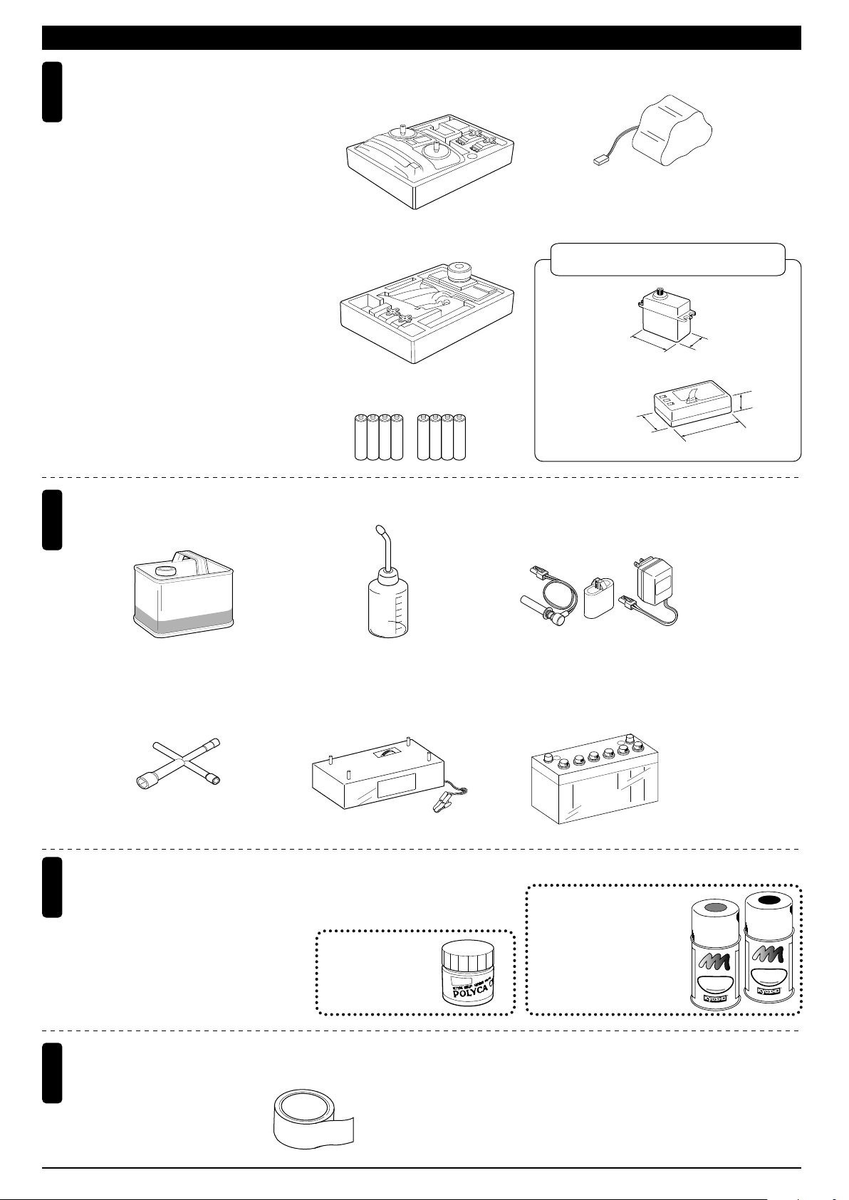
キットの他にそろえる物(1)REQUIRED FOR OPERATION (1)
2チャンネル2サーボ無線操縦機
1
(プロポ)
2ch radio control set with 2 servos.
●このキットには2チャンネル2サーボの
プロポが必要です。
●送信機にはスティックタイプとハンドル
タイプがありますが、お好みのタイプを
用意してください。
●ステアリングサーボは、リバースで使用
します。
●プロポの取扱いは、プロポに付属の説明
書を参考にしてください。
●This kit requires a 2 channel radio con-
trol set with 2 servos.
●Because there are stick-type and wheeltype transmitters, use which ever fits your
convenience best.
●Switch the reverse (transmitter) for the
throttle control.
●For more information on the radio con-trol
set, refer to its instruction manual.
■スティックタイプ
2チャンネルプロポ
Stick-type
2ch radio set.
■ハンドルタイプ
2チャンネルプロポ
Wheel-type
2ch radio set.
■単3乾電池(送信機用)
AA-size Batteries (For Transmitter)
AAAA
AAAA
■受信機用ニカドバッテリー
Ni-Cd Battery
No.71312 6V600mAh
RXニカドバッテリー
使用できるサーボ・受信機サイズ
Suitable servos & receiver
■サーボ
Servo
38〜41mm
■受信機
Receiver
25〜29mm
19〜20mm
36〜42.5mm
15〜17mm
燃料と始動用具
2
Required for engine starting:
■燃料
Glow Fuel
Glow Engine
uel
F
No.607002
RCモデルフュール
トルネード
■プラグレンチ
Plug Wrench
No.80312
ロッキングジグ/レンチ
Locking Jig & Wrench
塗料
3
Paint
●ボディの塗装には塗料が必要です。
京商では、 モデル用塗料、スプレー
を販売していますので ご利用ください。
●For painting the body, use Kyosho paints
for models!
■燃料ポンプ
Fuel Pump
No.96422
クイックフュールポンプ
Quick Fill Fuel Bottle
■スターター
Starter
No.2230
ポリカカラー
POLYCA COLOR
■プラグヒーター
Plug Heater
No.96411
ワンタッチプラグヒートセット
One-touch Plug Heater Set
■スターター用バッテリー
Battery
−
+
No.76501〜76711
京商スプレーカラー
KYOSHO SPRAY COLOR
U
F
E
T
L
P
R
N
I
O
F
A
F
P
U
F
E
L
P
R
O
F
F
K
Y
S
O
S
P
R
A
Y
C
K
T
N
I
A
P
O
H
R
O
L
O
R
O
Y
H
S
O
S
P
R
O
R
L
A
O
Y
C
R
その他
4
Other equipment required.
2
■グラステープ
Tape
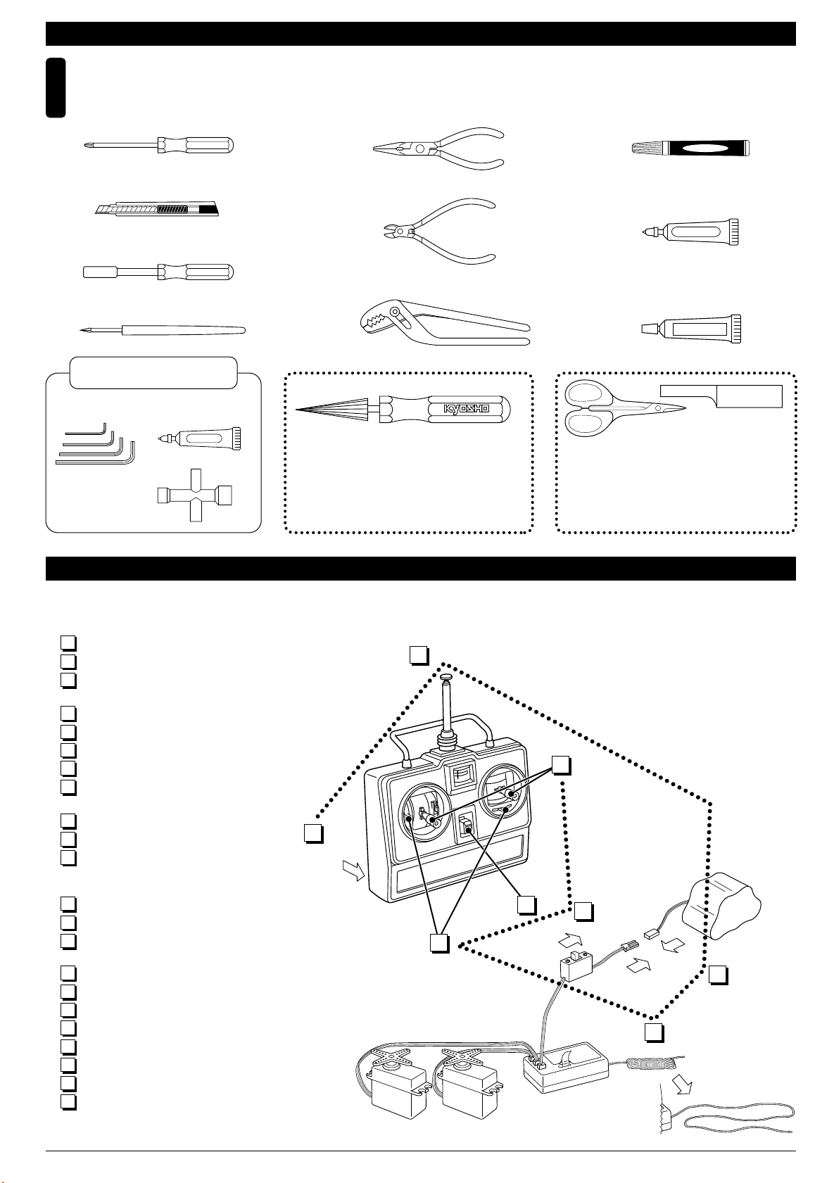
組立てに必要な工具
5
Tools required
キットの他にそろえる物(2)REQUIRED FOR OPERATION (2)
■+ドライバー(大、中、小)
Phillips Screwdriver ( L. M. S )
■カッターナイフ
Sharp Hobby Knife
■10mmボックスドライバー
Box Wrench
■キリ
Awl
キットに入っている工具
TOOLS INCLUDED
■六角レンチ
Hex Wrench
■十字レンチ(小)
Cross Wrench (S)
■グリス
Grease
Grease
■ラジオペンチ
Needle Nose Pliers
■ニッパー
Wire Cutters
■プライヤー
Pliers
No.80311
スペシャルテーパーリーマー
SPECIAL TAPER REAMER
下穴加工が不要で、直接
1mm〜15mmの正確な穴
あけができる工具です。
No need to pre-drill!
Drills neat 1mm to 15mm
holes directly!
■瞬間接着剤
Instant Glue
■ネジロック剤
Screw Cement
■ゴム系接着剤
Rubber Cement
No.1829
ラウンドカッター&サンダー
ROUND CUTTER & SANDER
ボディのカット、仕上
げ用。曲線部分も楽に
作業ができます。
ネジロック剤
ゴム系接着剤
For trimming bodies!
Cutting along curved lines
never was so easy!
プロポの準備 RADIO PREPARATION
●プロポを下の順番にしたがってセットします。
Set up the radio control system as indicated below.
1
単3乾電池をセットする(送信機)
アンテナをのばす(送信機)
2
充電した受信機用ニカドバッテリーをつ
3
なぐ。
アンテナをのばす(受信機)
4
トリムレバーを中央にセットする。
5
スイッチを入れる(送信機)
6
スイッチを入れる(受信機)
7
スティックを動かしてサーボが動くか確
8
認する。
スイッチを切る(受信機)
9
スイッチを切る(送信機)
10
アンテナを縮める。
11
Install batteries. (Transmitter)
1
Extend the antenna. (Transmitter)
2
Connect the charged Ni-Cd battery to
3
the receiver.
Extend the antenna. (Receiver)
4
Center the trims.
5
Switch on. (Transmitter)
6
Switch on. (Receiver)
7
Make sure the servos are in command.
8
Switch off. (Receiver)
9
Switch off. (Transmitter)
10
Retract the antenna. (Transmitter)
11
1
START
2
FINISH
8
6
7
5
3
4
3
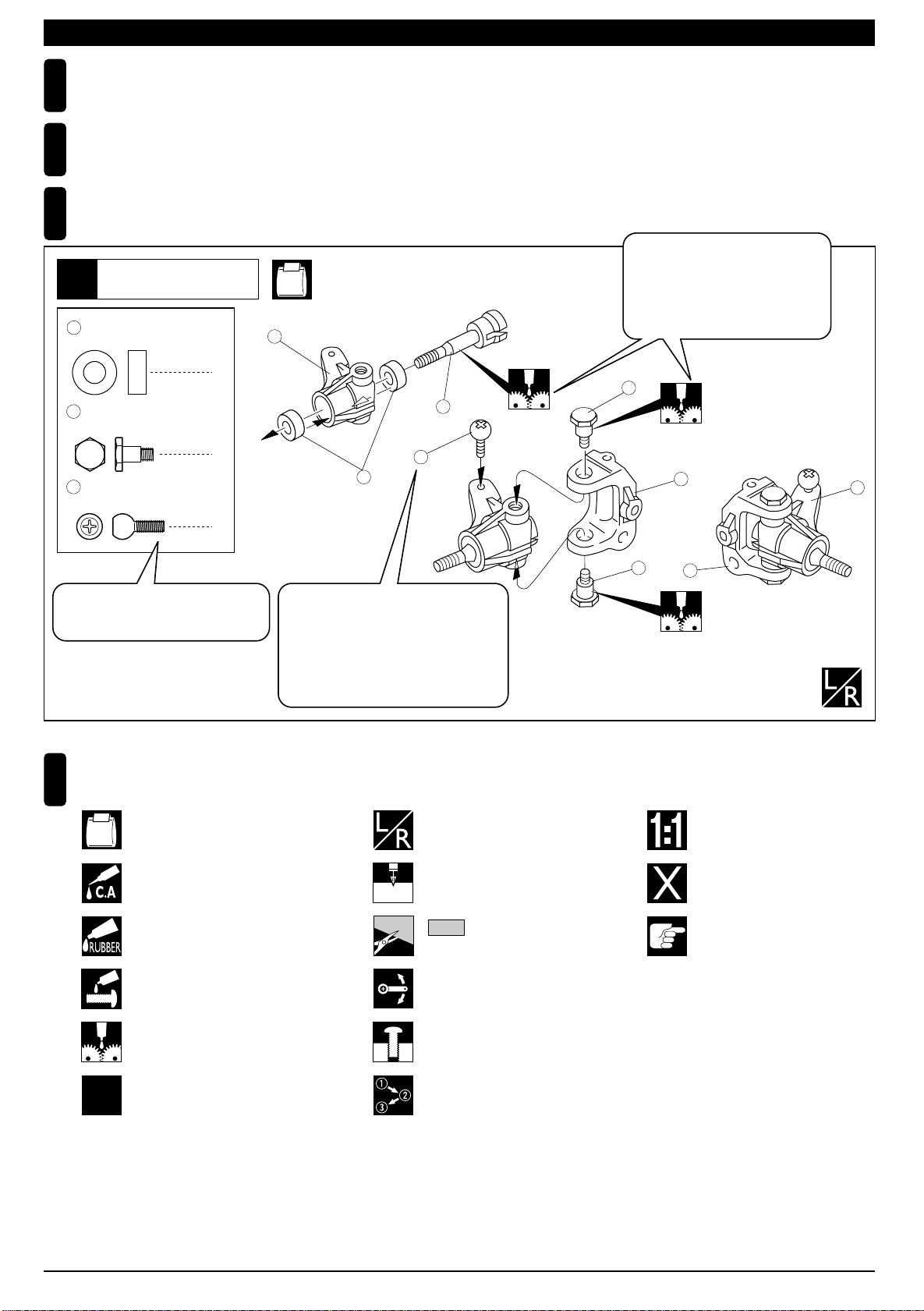
組立て前の注意(1) BEFORE YOU BEGIN (1)
組立てる前に説明書を良く読んで、おおよその構造を理解してから組立てに入ってください。
1
Read through the manual before you begin, so you will have an overall idea of what to do.
キットの内容をお確かめください。万一不良、不足がありましたら、お買い求めの販売店にご相談いただくか、
2
当社「ユーザー相談室」までご連絡ください。
Check all parts. If you find any defective or missing parts, contact your local dealer or our Kyosho Distributor.
説明書の見かた
3
How to read the instruction manual:
〔説明例 Example〕
説明書内では多くのマークが使用
フロントサスペンション
Front Suspension
1
4
5 x 10mm メタル
Metal Bushing
No.4, No.5, No.6
1
されています。マークに注意して
組立てを進めてください。
This instruction manual uses several symbols. Please note them
during the entire assembly.
4
キングピン
5
King Pin
4
5.8mm ピロボール(黒)
6
Pillow Ball (Black)
2
小物部品の名前、原寸図、使用数。
Key Number, Part Name, True-to-scale
Diagram, Quantity Used
キット内の部品は、ビス類を除いてキー
No.が付けられています。スペアパーツを
購入する時はキーNo.を参照して下さい。
All parts except screws are identified by
key numbers. For purchasing spare parts,
find the key no. of the part needed in the
spare part list and refer to the left column
to look up the corresponding order no.
説明書に使われているマーク
4
Symbols used throughout the instruction manual, comprise:
使用する袋詰。
Part bags used.
瞬間接着剤で接着する。
Apply instant glue (CA glue, super glue).
4
2mm
3
6
左右同じように組立てる。
Assemble left and right sides
the same way.
2mmの穴をあける(例)。
Drill holes with the specified
diameter (here: 2mm).
5
7
R
L
5
8
原寸図
True-to-scale diagram.
別購入品
Must be purchased separately!
2
x2
ゴム系接着剤で接着する。
Apply rubber cement.
ネジロック剤を塗る。
Apply threadlocker (screw cement).
グリスを塗る。
Apply grease.
2セット組立てる(例)。
Assemble as many times as
specified (here: twice).
をカットする。
Cut off shaded portion.
可動するように組立てる。
Ensure smooth non-binding
movement while assembling.
仮止め。
Tentatively tighten.
番号の順に組立てる。
Assemble in the specified
order.
注意して組立てる所。
Pay close attention here!
4
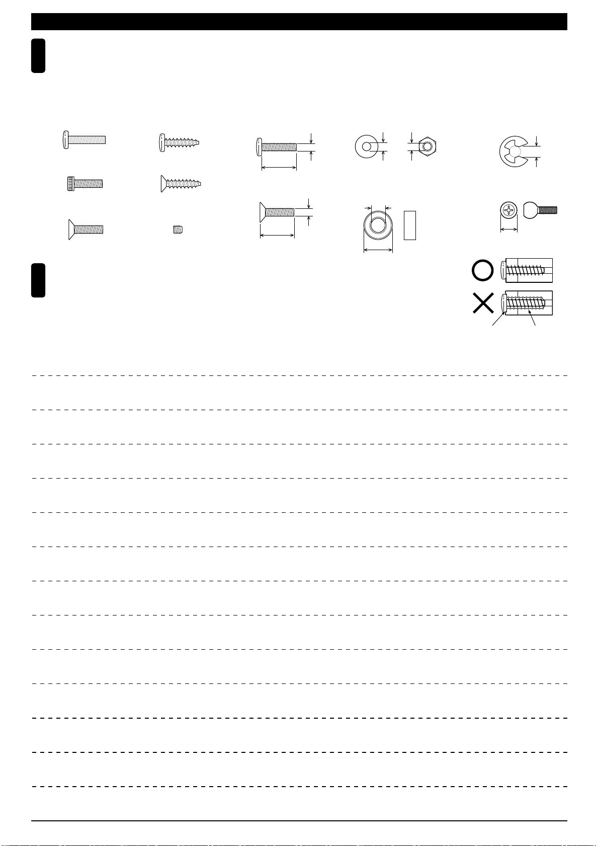
組立て前の注意(2) BEFORE YOU BEGIN (2)
キットには、形や長さが違うビスや小物部品が多く入っています。説明書には原寸図がありますので確認してから
5
組立ててください。また、ビス類は多めに入っているものもありますので、予備としてお使いください。
This kit contains screws and hardware in different metric sizes and shapes. Before using them, check the screws on the true-to-scale diagrams
on the left side in each assembly step. Some screws are extras.
●ビスの種類 SCREWS
ビス Screw
キャップビス
Cap Screw
サラビス
Flat Head (F/H) Screw
TPビス
Self-tapping (TP) Screw
TPサラビス
TP F/H Screw
セットビス
Set Screw
●小物部品のサイズ例 OTHER HARDWARE
3x12mmビス
Screw
3mm
12mm
3x12mmサラビス
F/H Screw
3mm
12mm
3mmワッシャー・ナット
Washer・Nut
5x10mmメタル・ベアリング
Metal Bushing・Bearing
5mm
10mm
TPビスは、部品にネジを切りながらしめつけるビスです。しめこみが固い場合が
6
ありますが、部品が確実に固定されるまでしめこんでください。ただし、しめす
ぎるとネジがきかなくなりますので、部品が変形するまでしめないでください。
Self-tapping (TP) screws cut threads into the parts when being tightened. Excessive force may
permanently damage parts when tightening TP screws. It is recommended to stop tightening when
the part is attached or when some resistance is felt after the threaded portion enters the plastic.
3mm
Correct
Wrong
しめすぎ
Overtightened.
E4Eリング
E-ring
4mm
5.8mmピロボール
Pillow Ball
5.8mm
ビスがきかない
The threads
are stripped.
5
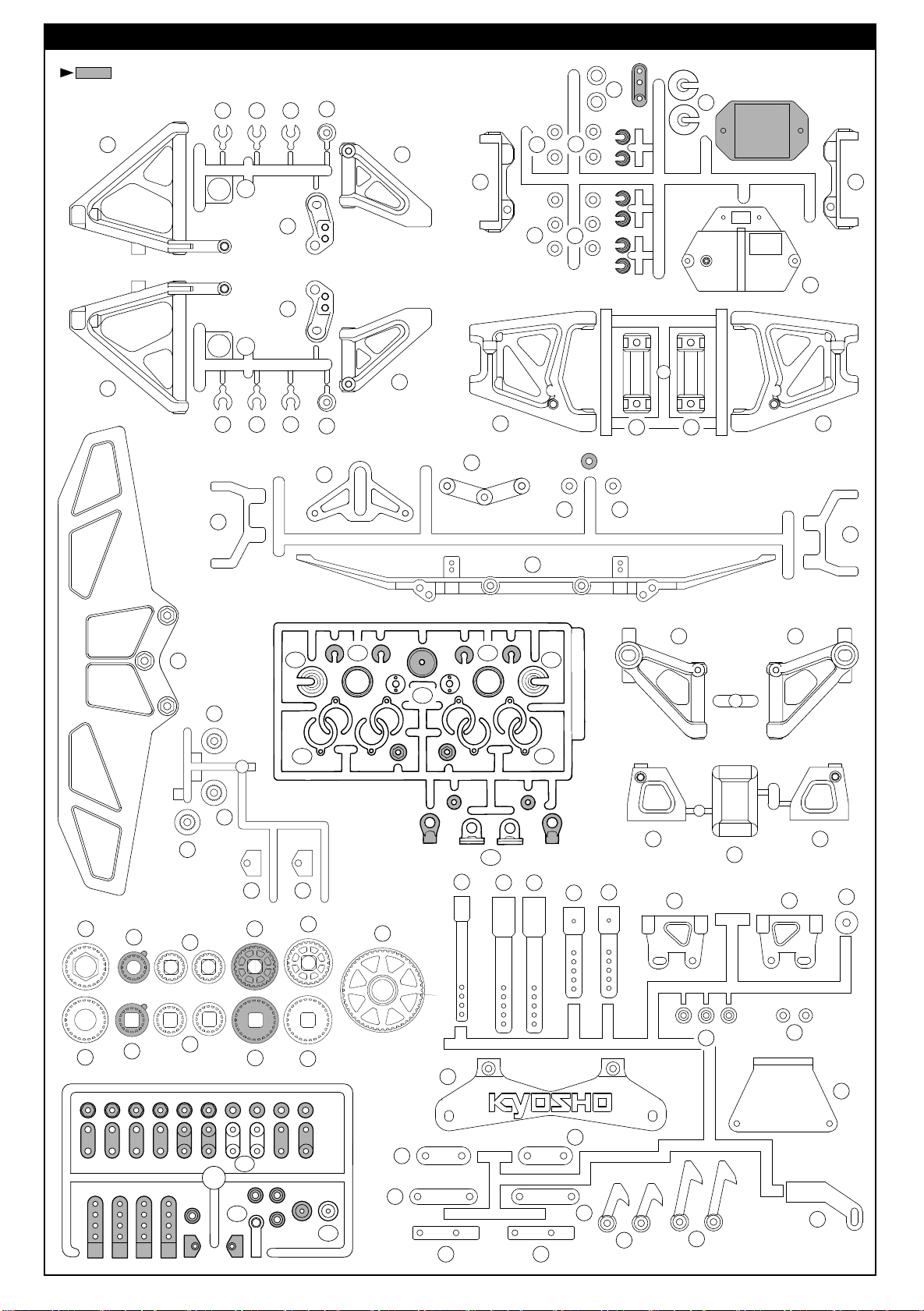
ランナー付プラパーツ配置図 ARRANGEMENT OF PLASTIC PARTS ON RUNNERS
部分の部品は、使用しません。
Shaded Parts are not used.
13 13 14
8
12
48
44
49
6
49
R
10
42
49
49
43
40
9
L
7
13 13 14
11
32
34
5
18
19
19
17
33
36
36
34
35
56
57
65
64
50
141E
141D 141D
16
141E
15
141A
70
F
K
H
141C
141C
69
202
58
59
197 197
60
25
61
62
26
63
66
207
141B
206
206
205
37 37
205
210
216
38
210
217
238
208
213
211
164A
211
212
164B
164C
212
214
218
215
209209
6
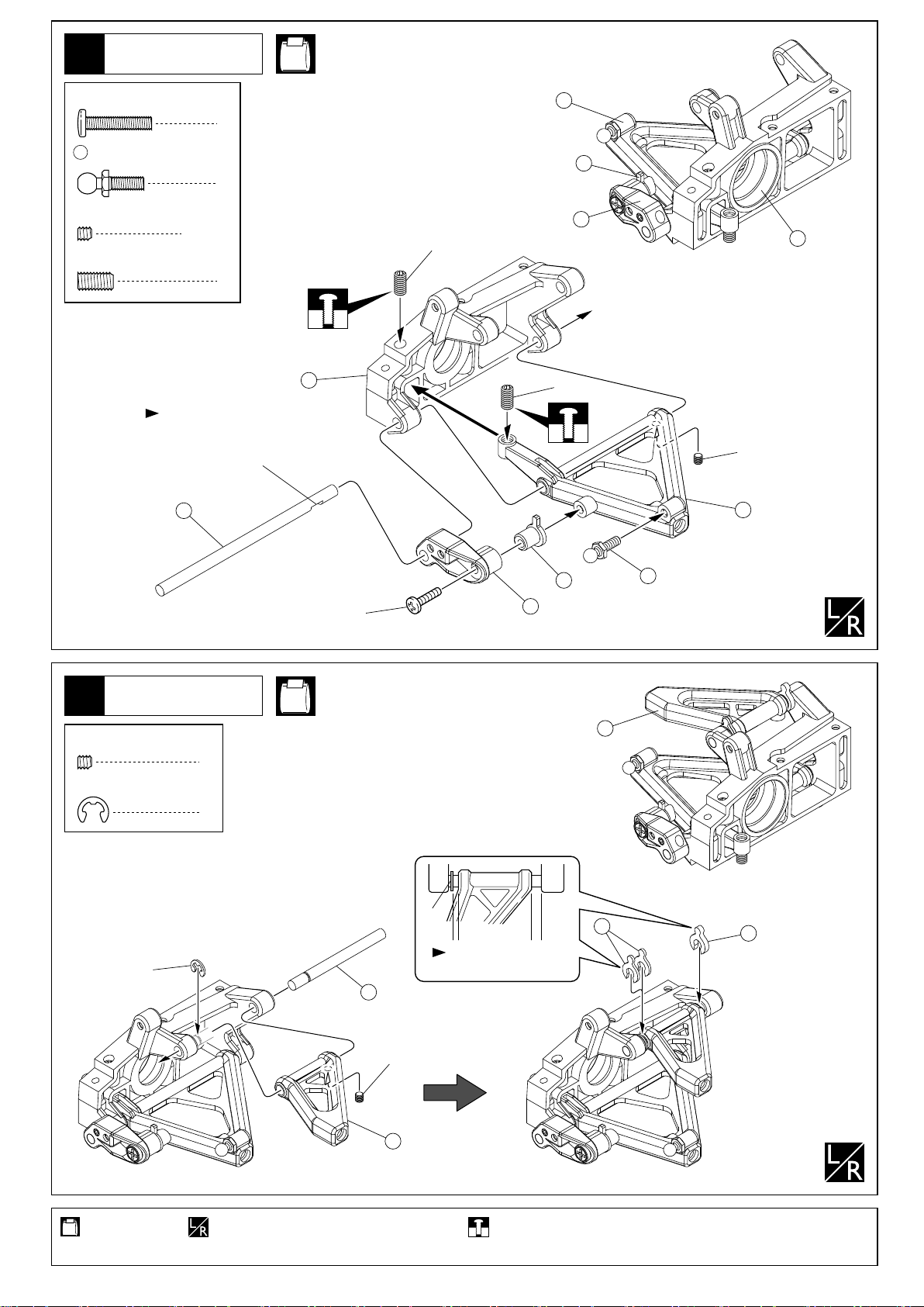
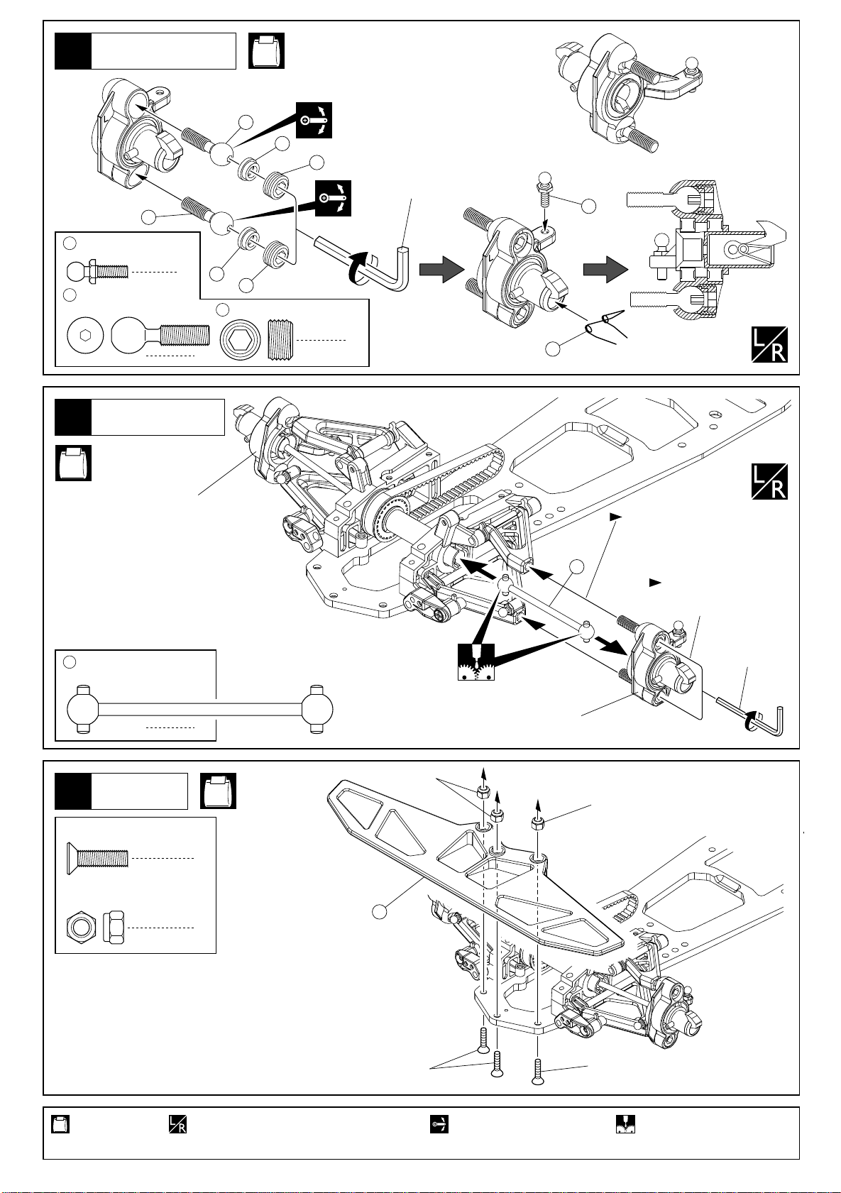
フロントサスペンション
Front Suspension
1
No.2, No.13
< Right >
右側用
3 x 15mm
Screw
99
4.8mm
Ball Stud
3 x 3mm
Set Screw
4 x 8mm
Set Screw
ビス
ボールスタッド
セットビス
セットビス
平らな面に3x3mmセットビス
を固定する。
Firmly tighten the 3x3mm set
screws onto the flat spots.
113
8
2
12
2
< Left >
左側用
2
4
4x8mm
22
10
23
4x8mm
3x3mm
7
フロントサスペンション
Front Suspension
2
3 x 3mm
Set Screw
E3
E-ring
< Left >
セットビス
Eリング
左側用
E3
99
3x15mm
No.2, No.13
11
9
< Right >
右側用
6
2
2
E3
このすき間に入れる。
Put into this space.
13
14
112
使用する袋詰。
Part bags used.
3x3mm
5
左右同じように組立てる。
Assemble left and right sides the same way.
仮止め。
Tentatively tighten.
7
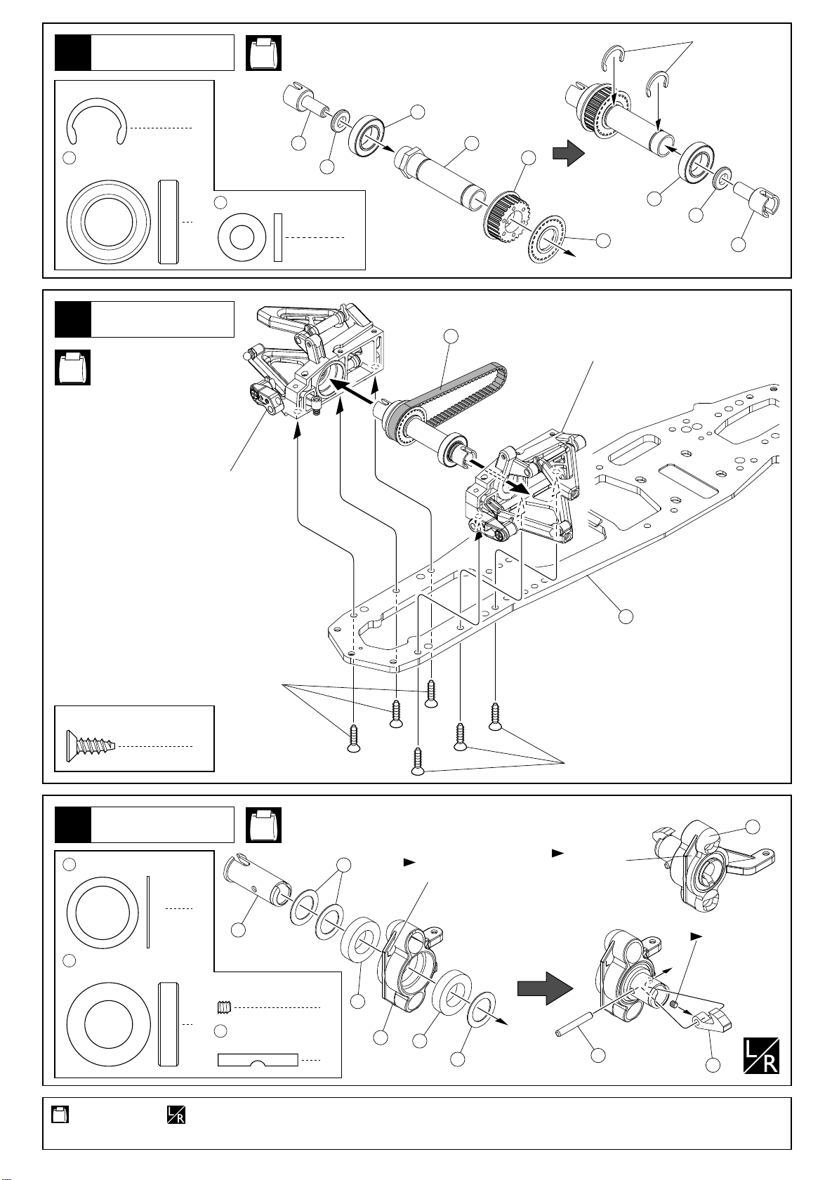
フロントシャフト
Front Shaft
3
No.1, No.2, No.13
Cリング
C-ring
Cリング
168
12x21x5mm
Ball Bearing
4
C-ring
ベアリング
フロントサスペンション
Front Suspension
No.2, No.13
< Right >
右側用
2
48
6 x 12 x 2mm
Collar
2
86
カラー
48
168
87
56
168
48
2
57
86
187
< Left >
左側用
4 x 12mm
TP F/H Screw
5
12 x 18 x 0.5mm
186
Washer
222
12x21x5mm
Metal Bushing
TPサラビス
フロントサスペンション
Front Suspension
ワッシャー
メタル
4x12mm
6
6
81
3 x 3mm
Set Screw
4
8523 x 20mm
Pin
No.1, No.3,
No.13
セットビス
ピン
117
4x12mm
< Right >
右側用
< Left >
左側用
Rのマーク。
"R" marked.
平らな面にセット
ビスを固定する。
Firmly tighten the
set screws onto
the flat spots.
85
1
Lのマーク。
"L" marked.
222
186
222
2
186
2
214
使用する袋詰。
Part bags used.
8
左右同じように組立てる。
Assemble left and right sides the same way.
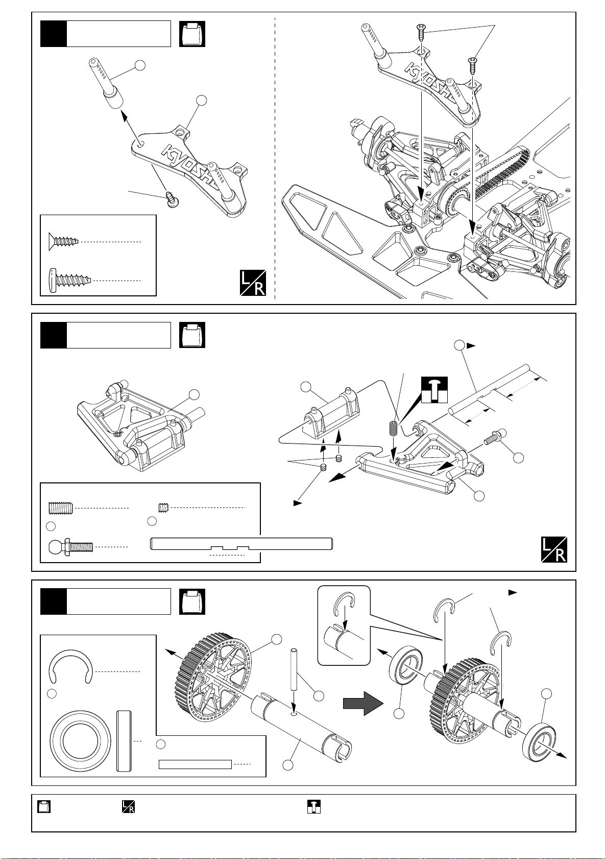
フロントサスペンション
Front Suspension
6
103
99
4.8mm
ボールスタッド
Ball Stud
9mm
103
7
ボールスクリュー
Ball Screw
フロントサスペンション
Front Suspension
< Left >
左側用
103
2
49
104
104
10mm
スクリューキャップ
Screw Cap
4
No.1, No.3, No.13
49
104
六角レンチ(5mm)
Hex Wrench (5mm)
4
111
99
< Right >
右側用
No.3, No.13
< Right >
右側用
83
フロントスイングシャフト
Front Swing Shaft
バンパー
Bumper
8
4 x 15mm
F/H Screw
サラビス
しめ込み量は別紙セッティング
データシートを参照。
Please refer to the Setting Data
83
< Left >
2
4mm
左側用
Sheet about the setting for screws.
交互に少しずつしめ込む。
Tighten screws one after
the other.
六角レンチ(2.5mm)
Hex Wrench (2.5mm)
No.1, No.13
4mm
3
4mm
ナイロンナット
Nylon Nut
使用する袋詰。
Part bags used.
50
3
4x15mm
左右同じように組立てる。
Assemble left and right sides the same way.
可動するように組立てる。
Ensure smooth non-binding
movement while assembling.
4x15mm
グリスを塗る。
Apply grease.
9
ボディマウント
Body Mounts
9
No.1, No.13
3x10mm
206
208
4x12mm
3 x 10mm
TP F/H Screw
4 x 12mm
TP Screw
TPサラビス
TPビス
リヤサスペンション
Rear Suspension
10
4 x 8mm
Set Screw
99
セットビス
4.8mm
ボールスタッド
Ball Stud
2
2
18
3 x 3mm
Set Screw
2
115
リヤロアーサスシャフト
Rear Lower Suspension Shaft
2
No.4, No.13
セットビス
< Left >< Right >
4
2
左側用右側用
3x3mm
4x8mm
19
平らな面にセットビスを固定する。
Firmly tighten the set screws
onto the flat spots.
115
向きに注意。
Note the direction.
短い
17
Short
99
長い
Long
リジッドアクスル
Rigid Axle
11
Cリング
168
12 x 21 x 5mm
Ball Bearing
使用する袋詰。
Part bags used.
C-ring
10
No.4, No.13
2
ベアリング
2
9113 x 25mm
Pin
左右同じように組立てる。
Assemble left and right sides the same way.
ピン
66
90
91
仮止め。
Tentatively tighten.
168
Cリング ゆるい場合は
C-ring
かしめる。
Tighten C-Ring
with wrench if
it is loose.
168
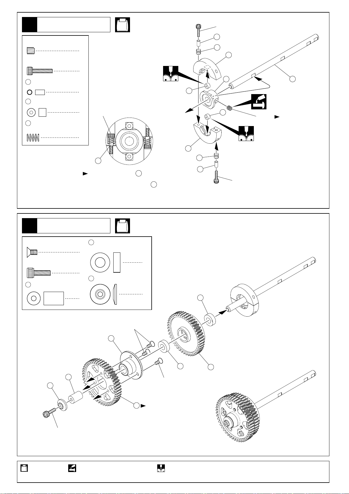
2スピードミッション
2 Speed Changer
12
4 x 4mm
Set Screw
2.6 x 12mm
Cap Screw
135
140
139
セットビス
キャップビス
2.6 x 3 x 5.5mm
Collar
5mm
ローラー
Roller
2速スプリング
2 Speed Spring
カラー
No.5, No.13
1
2
2
2
2.6x12mm
2
135
2.6mmキャップビスを カラーにあたる
までしめた所から4 回転ゆるめる。
Tighten 2.6mm Cap Screw to Collar till the
screw stops, and unscrew 4 rounds, then
please set up according to the track condition.
135
135
140
137
139
135
2.6x12mm
135
139
137
138
140
2.6x12mm
4x4mm
89
平らな面にセット
ビスを固定する。
Firmly tighten the
set screws onto
the flat spots.
2スピードミッション
2 Speed Changer
13
3 x 6mm
F/H Screw
3 x 10mm
Cap Screw
196
サラビス
キャップビス
3 x 8 x 12mm
Collar
201
カラー
196
136
6 x 12 x 4mm
Metal Bushing
3
1
3 x 12mm
201
Washer
1
134
No.5, No.13
メタル
ワッシャー
3x6mm
2
1
136
3x6mm
136
80
3x10mm
使用する袋詰。
Part bags used.
79
向きに注意。
Note the direction.
ネジロック剤を塗る。 グリスを塗る。
Apply threadlocker (screw cement). Apply grease.
11
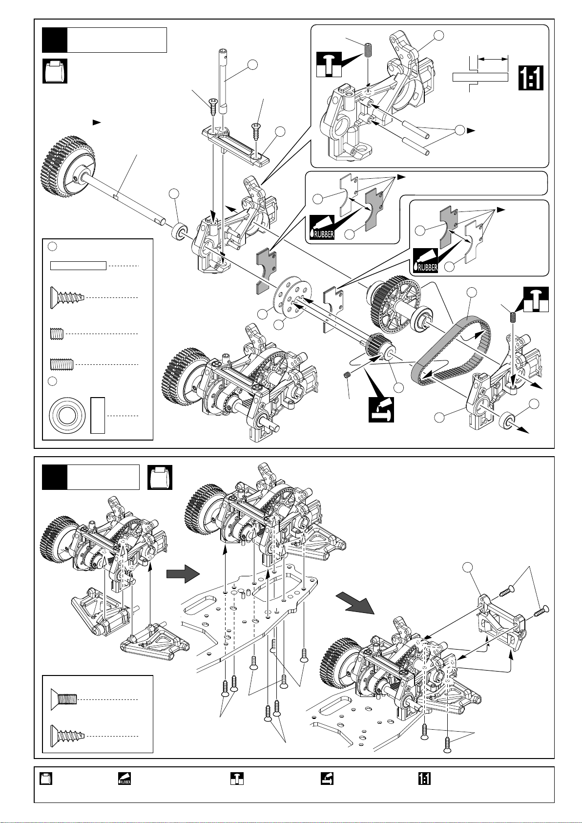
リヤASSY
Rear Assembly
14
No.1, No.6, No.13
4x12mm
97
4x12mm
4x8mm
25
11mm
平らな面にセット4x4mm
ビスを固定する。
Firmly tighten the 4x4mm
set screws onto the flat spots.
19823 x 20mm
Pin
4 x 12mm
TP F/H Screw
4 x 4mm
Set Screw
4 x 8mm
Set Screw
167
6 x 13 x 5mm
Ball Bearing
ピン
TPサラビス
セットビス
セットビス
ベアリング
198
奥までしっかり
圧入する。
Push to the end.
穴の内側の
バリをけずる。
Cut off excess
inside of the
holes.
167
26
95
96
穴の内側のバリをけずる。
Cut off excess inside of the holes.
96
95
2
189
4x8mm
94
94
1
2
93
4x4mm
2
24
167
リヤASSY
Rear Assembly
15
4 x 8mm
F/H Screw
4 x 12mm
TP F/H Screw
サラビス
TPサラビス
No.6, No.13
27
4
8
4x8mm
4x12mm
4x8mm
4x12mm
4x12mm
4x12mm
使用する袋詰。
Part bags used.
12
ゴム系接着剤で接着する。
Apply rubber type glue.
仮止め。
Tentatively tighten.
ネジロック剤を塗る。 原寸図。
Apply threadlocker
(screw cement).
True-to-scale diagram.
 Loading...