

Page 1
※ご使用前にこの説明書を良くお読みになり充分に理解してください。
Before commencing assembly, please read these instructions thoroughly!
R
THE FINEST RADIO CONTROL MODELS
組立/取扱説明書
INSTRUCTION MANUAL
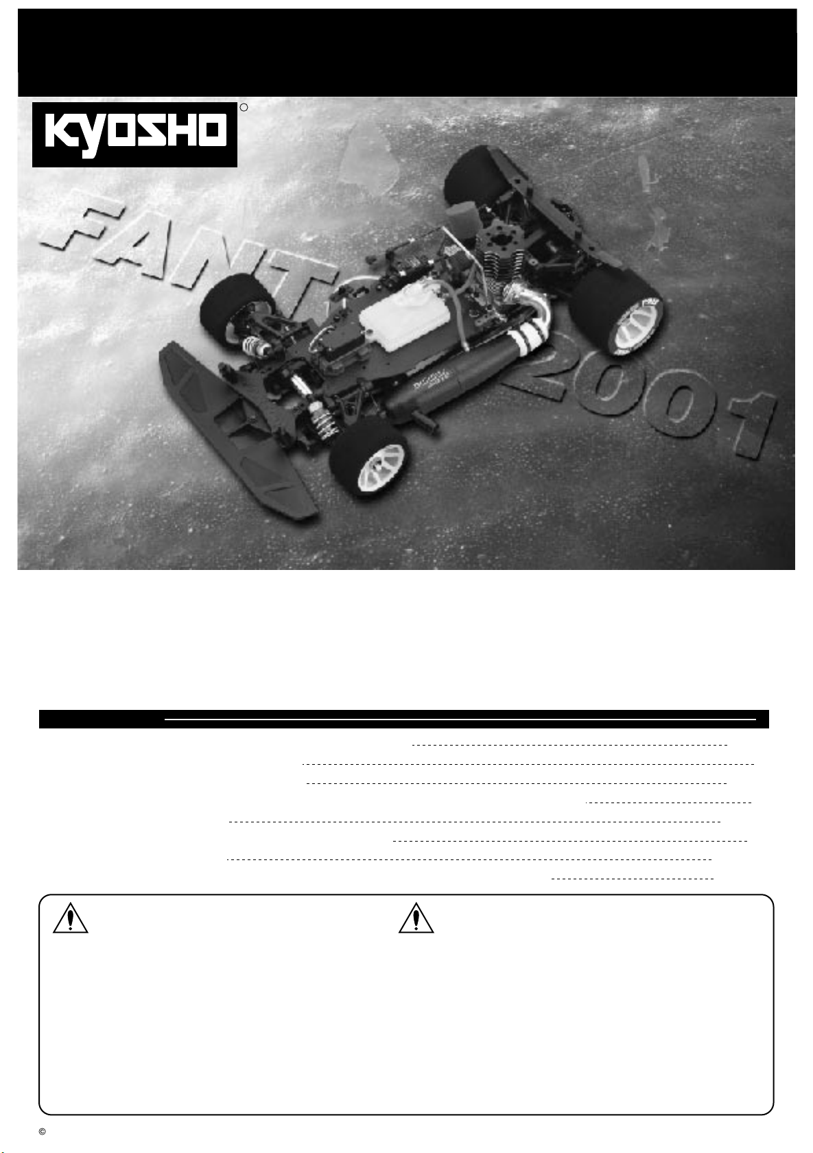
FANTOM 2001
1:8 Scale Radio Controlled .21 Engine Powered 4WD Racing Car
目 次 INDEX
●キットの他にそろえる物 REQUIRED FOR OPERATION
●プロポの準備RADIO PREPARATION
●組立て前の注意 BEFORE YOU BEGIN
●ランナー付プラパーツ配置図 ARRANGEMENT OF PLASTIC PARTS ON RUNNERS
●本体の組立て ASSEMBLY
●取扱いの注意 OPERATING YOUR MODEL SAFELY
●分解図 EXPLODED VIEW
●スペアパーツ・オプションパーツリスト SPARE PARTS & OPTIONAL PARTS
安全のための注意事項 SAFETY PRECAUTIONS
ファントム2001
2 〜 3
4 〜 5
7 〜 26
28 〜
29 30 〜
3
6
27
This radio control model is not a toy.この無線操縦模型は玩具ではありません!
●この商品は高い性能を発揮するように設計されています。
組立てに不慣れな方は、模型を良く知っている人にアド
バイスを受け確実に組立ててください。
●小さい部品があるので、組立て作業は、幼児の手がとど
かない所で必ず行ってください。
●動かして楽しむ場所は万一の事故を考えて、安全を確認
してから責任をもってお楽しみください。
●組立てた後も、説明書がいつでも見られるように大切に
保管してください。
※製品改良のため、予告なく仕様を変更する場合があります。 SPECIFICATIONS ARE SUBJECT TO CHANGE WITHOUT NOTICE.
2000 KYOSHO/禁無断転載複製
●First-time builders should seek the advice of experienced modellers
before commencing assembly and if they do not fully understand
any part of the construction.
●Assemble this kit only in places out of children's reach!
●Take care before operating this model.
You are responsible for this model's assembly and safe operation!
●Always keep this instruction manual ready at hand for quick
reference, even after completing the assembly.
No. 31999
Page 2
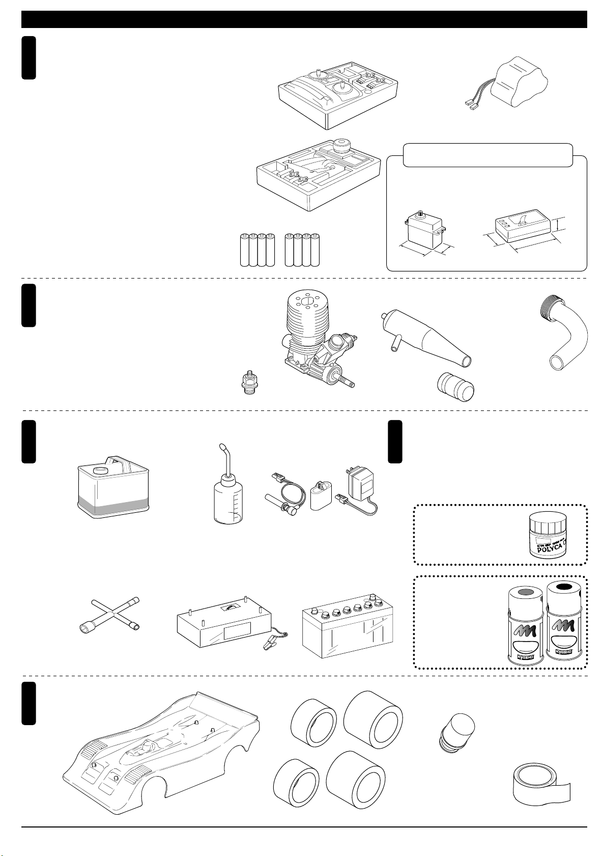
キットの他にそろえる物(1)REQUIRED FOR OPERATION (1)
2チャンネル2サーボ無線操縦機
1
(プロポ)
2ch radio control set with 2 servos.
●このキットには2チャンネル2サーボの
プロポが必要です。
●送信機にはスティックタイプとハンドル
タイプがありますが、お好みのタイプを
用意してください。
●スロットルサーボは、リバースで使用し
ます。
●プロポの取扱いは、プロポに付属の説明
書を参考にしてください。
●This kit requires a 2 channel radio con-
trol set with 2 servos.
●Because there are stick-type and wheeltype transmitters, use which ever fits
your convenience best.
●Switch the reverse (transmitter) for the
throttle control.
●For more information on the radio con-trol
set, refer to its instruction manual.
エンジンおよびマフラー
2
Engine & Muffler
●このキットには21クラスエンジンが必要
です。
●This kit requires a .21 class engine.
■スティックタイプ
2チャンネルプロポ
Stick-type
2ch radio set.
■ハンドルタイプ
2チャンネルプロポ
Wheel-type
2ch radio set.
■単3乾電池(送信機用)
AA-size Batteries (For Transmitter)
AAAA
AAAA
■21クラスカー用
エンジン
Engine for .21-
class cars
■プラグ
Plug
■サーボ
Servo
38〜41mm
■マフラー
Muffler
■受信機用ニカドバッテリー
Ni-Cd Battery
No.71321 6V600mAh
RXニカドバッテリー
使用できるサーボ・受信機サイズ
Suitable servos & receiver
■受信機
Receiver
25〜29mm
19〜20mm
■マニホールド
Manifold
36〜42.5mm
15〜17mm
燃料と始動用具
3
Required for engine starting:
■燃料
Glow Fuel
Glow En
No.607002
RCモデルフュール
トルネード
■プラグレンチ
Plug Wrench
No.80312
ロッキングジグ/レンチ
Locking Jig & Wrench
Fue
gine
l
■燃料ポンプ
Fuel Pump
No.96422
クイックフュールポンプ
Quick Fill Fuel Bottle
■スターター
Starter
■プラグヒーター
Plug Heater
No.96411
ワンタッチプラグヒートセット
One-touch Plug Heater Set
■スターター用バッテリー
Battery
+
■ジョイントパイプ
Joining Pipe
塗料
4
Paint
●ボディの塗装には塗料が必要です。京商では、
モデル用塗料、スプレーを販売していますので
ご利用ください。
●For painting the body, use Kyosho paints
for models!
No.2230
ポリカカラー
−
POLYCA COLOR
No.76501〜76711
京商スプレーカラー
KYOSHO SPRAY COLOR
No.92515
マフラージョイントパイプ
Muffler Joining Pipe
U
U
F
E
L
P
R
O
K
Y
O
S
P
R
A
Y
F
T
N
I
F
A
F
P
S
P
O
H
S
R
O
L
O
C
R
E
T
L
P
R
N
I
O
F
A
F
P
K
O
Y
H
S
O
R
O
R
L
A
O
Y
C
R
その他
5
Other equipment required.
■ボディ
Body
2
■タイヤ
Tire
■エアフィルター
Air Filter
■グラステープ
Tape
No.PC-7007
Page 3
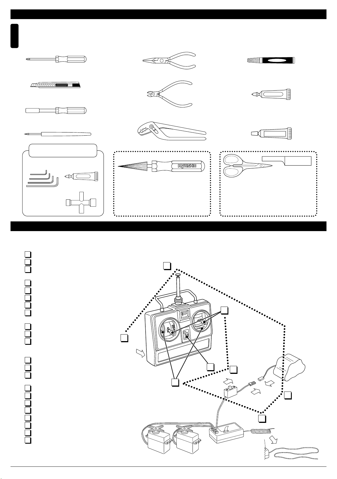
組立てに必要な工具
Tools required
6
キットの他にそろえる物(2)REQUIRED FOR OPERATION (2)
■+ドライバー(大、中、小)
Phillips Screw Driver (L.M.S)
■カッターナイフ
Sharp Hobby Knife
■10mmボックスドライバー
Box Wrench
■キリ
Awl
キットに入っている工具
TOOLS INCLUDED
■六角レンチ
Hex Wrench
■十字レンチ(小)
Cross Wrench (S)
■グリス
Grease
Grease
■ラジオペンチ
Needle Nose Pliers
■ニッパー
Wire Cutters
■プライヤー
Pliers
No.80311
スペシャルテーパーリーマー
SPECIAL TAPER REAMER
下穴加工が不要で、直接
1mm〜15mmの正確な穴
あけができる工具です。
No need to pre-drill!
Drills neat 1mm to 15mm
holes directly!
■瞬間接着剤
Instant Glue
■ネジロック剤
Screw Cement
■ゴム系接着剤
Rubber Cement
ゴム系接着剤
No.1829
ラウンドカッター&サンダー
ROUND CUTTER & SANDER
ボディのカット、仕上
げ用。曲線部分も楽に
作業ができます。
ネジロック剤
For trimming bodies!
Cutting along curved lines
never was so easy!
プロポの準備 RADIO PREPARATION
●プロポを下の順番にしたがってセットします。
Set up the radio control system as indicated below.
1
単3乾電池をセットする(送信機)
アンテナをのばす(送信機)
2
充電した受信機用ニカドバッテリーをつ
3
なぐ。
アンテナをのばす(受信機)
4
トリムレバーを中央にセットする。
5
スイッチを入れる(送信機)
6
スイッチを入れる(受信機)
7
スティックを動かしてサーボが動くか確
8
認する。
スイッチを切る(受信機)
9
スイッチを切る(送信機)
10
アンテナを縮める。
11
Install batteries. (Transmitter)
1
Extend the antenna. (Transmitter)
2
Connect the charged Ni-Cd battery to
3
the receiver.
Extend the antenna. (Receiver)
4
Center the trims.
5
Switch on. (Transmitter)
6
Switch on. (Receiver)
7
Make sure the servos are in command.
8
Switch off. (Receiver)
9
Switch off. (Transmitter)
10
Retract the antenna. (Transmitter)
11
1
START
2
FINISH
8
6
7
5
3
4
3
Page 4
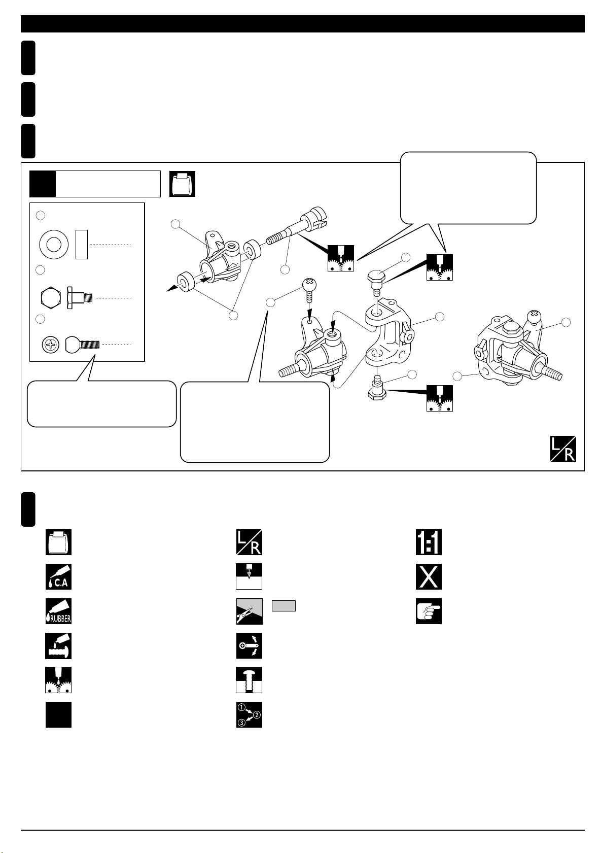
組立て前の注意(1) BEFORE YOU BEGIN (1)
組立てる前に説明書を良く読んで、おおよその構造を理解してから組立てに入ってください。
1
Read through the manual before you begin, so you will have an overall idea of what to do.
キットの内容をお確かめください。万一不良、不足がありましたら、お買い求めの販売店にご相談いただくか、
2
当社「ユーザー相談室」までご連絡ください。
Check all parts. If you find any defective or missing parts, contact your local dealer or our Kyosho Distributor.
説明書の見かた
3
How to read the instruction manual:
〔説明例 Example〕
説明書内では多くのマークが使用
フロントサスペンション
Front Suspension
1
4
5 x 10mm メタル
Metal Bushing
キングピン
5
King Pin
No.4, No.5, No.6
1
4
3
されています。マークに注意して
組立てを進めてください。
This instruction manual uses several symbols. Please note them
during the entire assembly.
5
4
5.8mm ピロボール(黒)
6
Pillow Ball (Black)
2
小物部品の名前、原寸図、使用数。
Key Number, Part Name, True-to-scale
Diagram, Quantity Used
キット内の部品は、ビス類を除いてキー
No.が付けられています。スペアパーツを
購入する時はキーNo.を参照して下さい。
All parts except screws are identified by
key numbers. For purchasing spare parts,
find the key no. of the part needed in the
spare part list and refer to the left column
to look up the corresponding order no.
説明書に使われているマーク
4
Symbols used throughout the instruction manual, comprise:
使用する袋詰。
Part bags used.
瞬間接着剤で接着する。
Apply instant glue (CA glue, super glue).
4
2mm
6
左右同じように組立てる。
Assemble left and right sides
the same way.
2mmの穴をあける(例)。
Drill holes with the specified
diameter (here: 2mm).
7
R
L
5
8
原寸図
True-to-scale diagram.
別購入品
Must be purchased separately!
2
x2
ゴム系接着剤で接着する。
Apply rubber cement.
ネジロック剤を塗る。
Apply threadlocker (screw cement).
グリスを塗る。
Apply grease.
2セット組立てる(例)。
Assemble as many times as
specified (here: twice).
をカットする。
Cut off shaded portion.
可動するように組立てる。
Ensure smooth non-binding
movement while assembling.
仮止め。
Tentatively tighten.
番号の順に組立てる。
Assemble in the specified
order.
注意して組立てる所。
Pay close attention here!
4
Page 5
組立て前の注意(2) BEFORE YOU BEGIN (2)
キットには、形や長さが違うビスや小物部品が多く入っています。説明書には原寸図がありますので確認してから組立て
5
てください。また、ビス類は多めに入っているものもありますので、予備としてお使いください。
This kit contains screws and hardware in different metric sizes and shapes. Before using them, check the screws on the true-to-scale diagrams on the
left side in each assembly step. Some screws are extras.
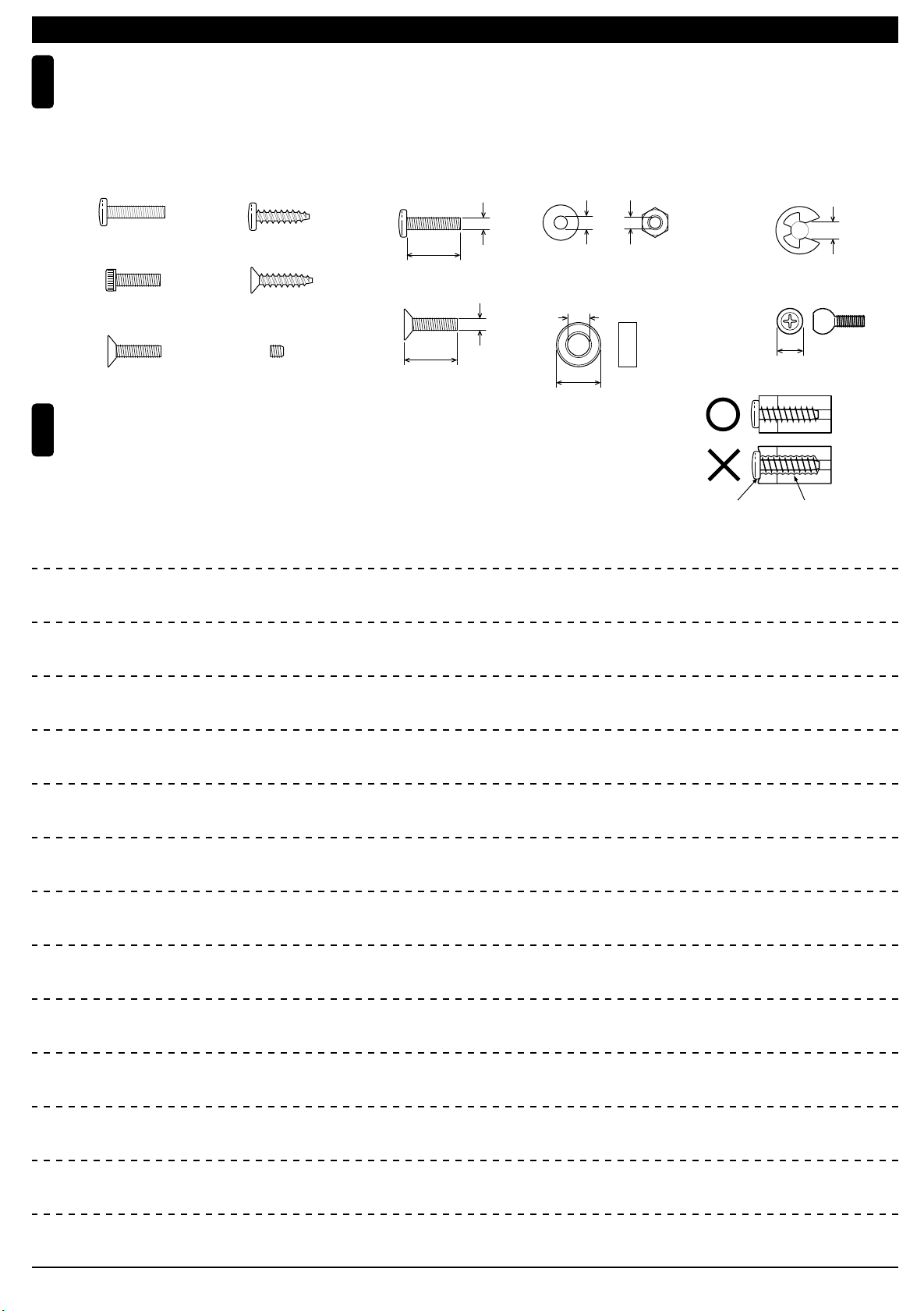
●ビスの種類 SCREWS
ビス Screw
キャップビス
Cap Screw
サラビス
Flat Head (F/H) Screw
TPビス
Self-tapping (TP) Screw
TPサラビス
TP F/H Screw
セットビス
Set Screw
●小物部品のサイズ例 OTHER HARDWARE
3x12mmビス
Screw
12mm
3x12mmサラビス
F/H Screw
3mm
12mm
3mmワッシャー・ナット
Washer・Nut
3mm
5x10mmメタル・ベアリング
Metal Bushing・Bearing
5mm
10mm
TPビスは、部品にネジを切りながらしめつけるビスです。しめこみが固い場合が
6
ありますが、部品が確実に固定されるまでしめこんでください。ただし、しめす
ぎるとネジがきかなくなりますので、部品が変形するまでしめないでください。
Self-tapping (TP) screws cut threads into the parts when being tightened. Excessive force may
permanently damage parts when tightening TP screws. It is recommended to stop tightening when
the part is attached or when some resistance is felt after the threaded portion enters the plastic.
3mm
Correct
Wrong
しめすぎ
Overtightened.
E4Eリング
E-ring
4mm
5.8mmピロボール
Pillow Ball
5.8mm
ビスがきかない
The threads are stripped.
5
Page 6
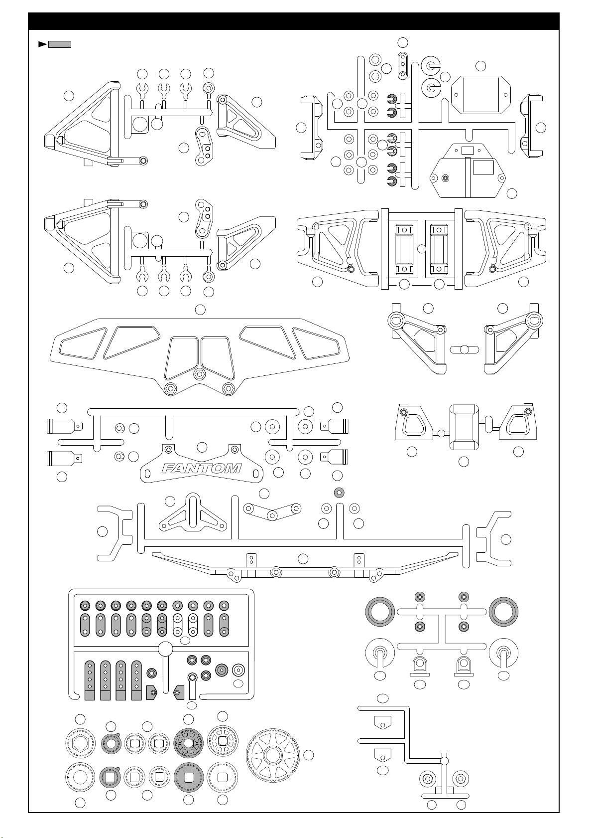
ランナー付プラパーツ配置図 ARRANGEMENT OF PLASTIC PARTS ON RUNNERS
部分の部品は、使用しません。
Shaded Parts are not used.
13 13 14
8
R
L
7
13 13 14
10
9
50
12
11
39
48
41
44
6
42
49
49
43
46
49
49
40
5
18
19
19
16
17
15
52
54
54
52
34
56 60
64 58
32
164A
164B
51
62
164C
55
33
55
35
55
55
36
53
53
36
141B
197
37 37
38
34
141B
141A 141A
66
26
63
197
F
K
70 69
57
65 59
25
61
6
Page 7

フロントサスペンション
Front Suspension
1
No.1, No.3, No.11
< Right >
右側用
3 x 18mm
F/H Screw
165
3mm
F/H Washer
99
4.8mm
Ball Stud
3 x 3mm
Set Screw
4 x 8mm
Set Screw
サラビス
サラワッシャー
ボールスタッド
セットビス
セットビス
平らな面に3x3mmセットビス
を固定する。
Firmly tighten the 3x3mm set
screws onto the flat spots.
113
8
2
12
2
< Left >
左側用
2
2
4
4x8mm
22
10
23
4x8mm
3x3mm
7
フロントサスペンション
Front Suspension
2
3 x 3mm
Set Screw
37
< Left >
セットビス
E3
Eリング
E-ring
左側用
37
99
3x18mm
No.1, No.3, No.11
11
9
165
< Right >
右側用
6
2
2
37
13
このすき間に入れる。
Put into this space.
14
112
使用する袋詰。
Part bags used.
3x3mm
5
左右同じように組立てる。
Assemble left and right sides the same way.
仮止め。
Tentatively tighten.
7
Page 8
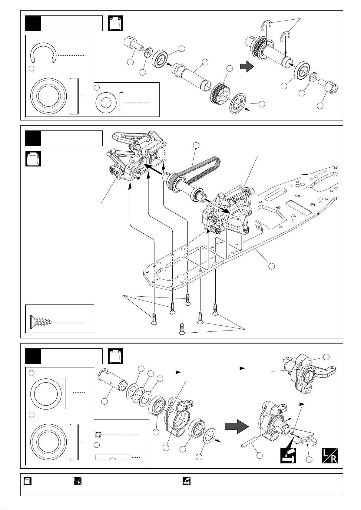
フロントシャフト
Front Shaft
3
No.1, No.4, No.11
Cリング
C-ring
Cリング
168
12x21x5mm
Ball Bearing
4
C-ring
ベアリング
フロントサスペンション
Front Suspension
No.4, No.11
< Right >
右側用
2
48
6 x 12 x 2mm
Collar
2
86
カラー
48
168
87
56
168
48
2
57
86
187
< Left >
左側用
4 x 12mm
TP F/H Screw
5
12 x 18 x 0.5mm
186
Washer
168
12x21x5mm
Ball Bearing
TPサラビス
フロントサスペンション
Front Suspension
ワッシャー
ベアリング
4x12mm
6
8
81
3 x 3mm
Set Screw
4
8523 x 20mm
Pin
No.3, No.11
セットビス
ピン
186
117
4x12mm
< Right >
右側用
< Left >
左側用
Rのマーク。
"R" marked.
85
平らな面にセット
ビスを固定する。
Firmly tighten the
set screws onto
the flat spots.
75
1
Lのマーク。
"L" marked.
168
186
186
168
2
186
2
使用する袋詰。
Part bags used.
8
左右同じように組立てる。
Assemble left and right sides the same way.
ネジロック剤を塗る。
Apply threadlocker (screw cement).
Page 9
フロントサスペンション
Front Suspension
6
103
99
4.8mm
ボールスタッド
Ball Stud
9mm
103
7
ボールスクリュー
Ball Screw
フロントサスペンション
Front Suspension
< Left >
左側用
103
2
49
104
104
10mm
スクリューキャップ
Screw Cap
4
No.1, No.3, No.11
49
104
六角レンチ(5mm)
Hex Wrench (5mm)
4
111
99
< Right >
右側用
No.4, No.11
< Right >
右側用
83
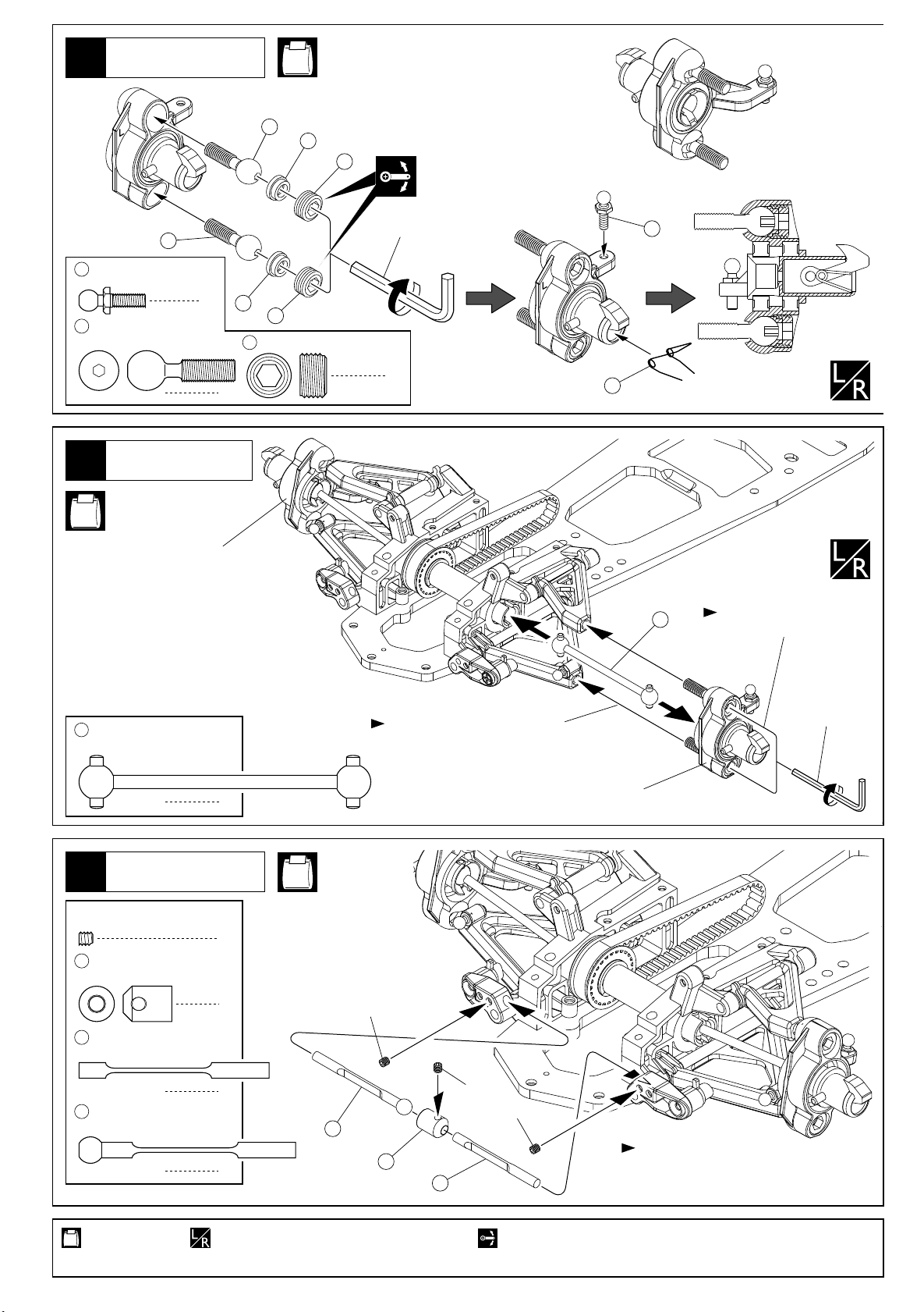
フロントスイングシャフト
Front Swing Shaft
フロントスタビライザー
Front Stabilizer
8
3 x 3mm
Set Screw
107
セットビス
フロントスタビカップ
Front Stabilizer Cup
83
しめ込み量は別紙セッティング
データシートを参照。
Please refer to the Setting Data Sheet
about the setting for screws.
< Left >
2
左側用
交互に少しずつしめ込む。
Tighten screws one after
the other.
六角レンチ(2.5mm)
Hex Wrench (2.5mm)
No.4, No.11
3
106
フロントスタビシャフト(B)
Front Stabilizer Shaft
105
フロントスタビシャフト(A)
Front Stabilizer Shaft
使用する袋詰。
Part bags used.
1
1
3x3mm
105
1
107
106
左右同じように組立てる。
Assemble left and right sides the same way.
3x3mm
3x3mm
スタビライザーの調整は別紙セッティング
データシートを参照。
Please refer to the Setting Data Sheet
about the setting for Stabilizer.
可動するように組立てる。
Ensure smooth non-binding movement while assembling.
9
Page 10
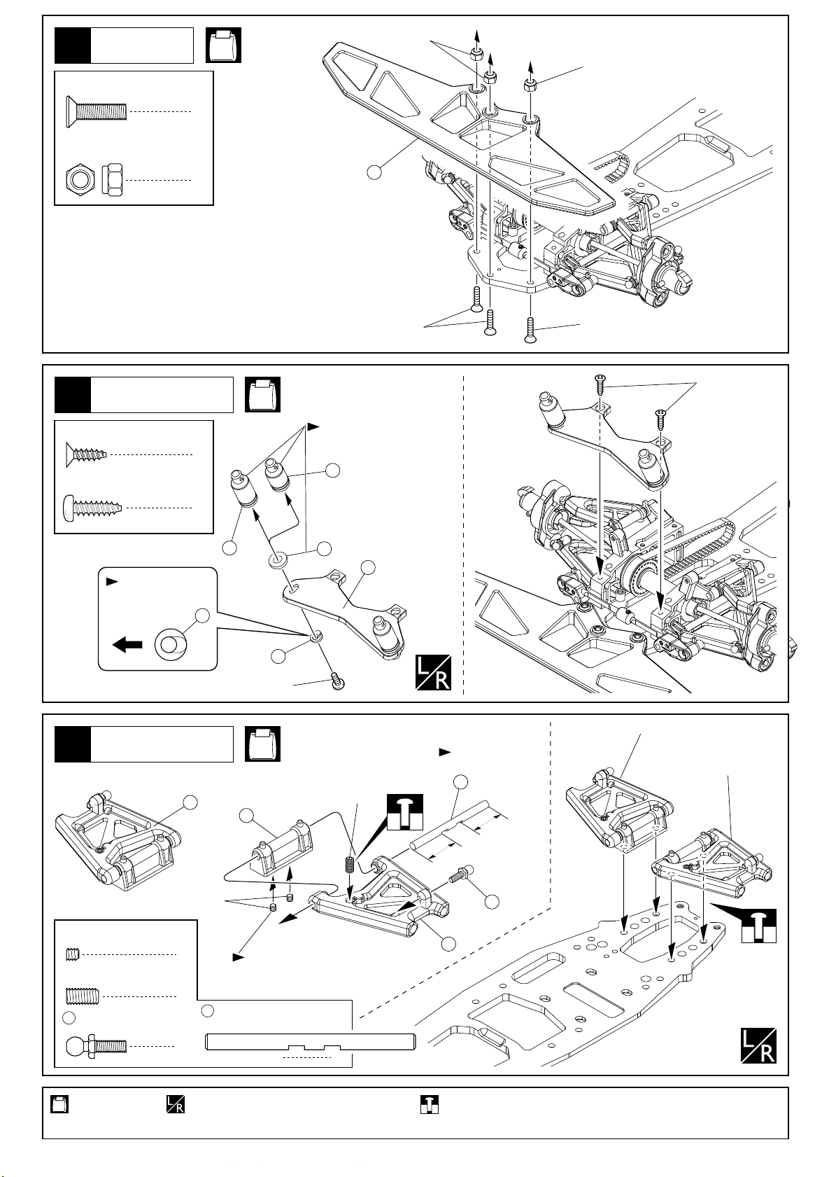
バンパー
Bumper
9
4 x 15mm
F/H Screw
4mm
Nylon Nut
サラビス
ナイロンナット
No.1, No.11
3
3
4mm
4mm
50
ボディマウント
Body Mounts
10
3 x 10mm
TP F/H Screw
4 x 12mm
TP Screw
11
< Right >
右側用
TPサラビス
TPビス
向きに注意。
Note the direction.
前
Front
リヤサスペンション
Rear Suspension
18
4x15mm
4x15mm
3x10mm
No.1, No.11
ボディに合わせる。
Adjust to body shell.
2
53
2
52
55
51
54
54
4x12mm
< Right >
右側用
No.1, No.6
< Left >
左側用
4x8mm
向きに注意。
Note the direction.
115
< Left >
左側用
19
短い Short
3 x 3mm
Set Screw
4 x 8mm
Set Screw
99
セットビス
セットビス
4.8mm
ボールスタッド
Ball Stud
使用する袋詰。
Part bags used.
10
3x3mm
4
2
115
2
左右同じように組立てる。
Assemble left and right sides the same way.
平らな面にセットビスを固定する。
Firmly tighten the set screws
onto the flat spots.
リヤロアーサスシャフト
Rear Lower Suspension Shaft
2
長い Long
99
17
仮止め。
Tentatively tighten.
Page 11

リジッドアクスル
Rigid Axle
12
Cリング
168
12x21x5mm
Ball Bearing
C-ring
ベアリング
2
2
9113 x 25mm
Pin
No.6, No.11
ピン
66
90
91
168
Cリング
C-ring
ゆるい場合は
かしめる。
Tighten C-Ring
with wrench if
it is loose.
168
2スピードミッション
2 Speed Changer
13
4 x 4mm
Set Screw
2.6 x 12mm
Cap Screw
135
140
136
139
セットビス
キャップビス
2.6 x 3 x 5.5mm
Collar
5mm
ローラー
Roller
6 x 12 x 4mm
Ball Bearing
2速スプリング
2 Speed Spring
ベアリング
カラー
No.7, No.11
1
2
2
2.6x12mm
2
1
135
2.6mmキャップビスを カラーにあたる
までしめた所から2.5回転ゆるめる。
2
Tighten 2.6mm Cap Screw to Collar till the
screw stops, and unscrew 2.5 rounds, then
please set up according to the track condition.
135
135
136
140
137
139
135
2.6x12mm
135
139
137
138
140
2.6x12mm
4x4mm
89
平らな面にセット
ビスを固定する。
Firmly tighten the
set screws onto
the flat spots.
2スピードミッション
2 Speed Changer
14
3 x 6mm
F/H Screw
3 x 10mm
Cap Screw
3 x 12mm
Washer
136
197
使用する袋詰。 ゴム系接着剤で接着する。
Part bags used.
サラビス
キャップビス
ワッシャー
6 x 12 x 4mm
3 x 8 x 12mm
Collar
ベアリング
Ball Bearing
カラー
3
1
1
197
3x12mm
1
1
3x10mm
Apply rubber type glue.
No.7, No.11
3x6mm
136
134
80
3x6mm
79
向きに注意。
Note the direction.
ネジロック剤を塗る。 グリスを塗る。
Apply threadlocker (screw cement). Apply grease.
11
Page 12

リヤASSY
Rear Assembly
15
No.1, No.6, No.11
4x12mm
97
4x12mm
4x8mm
25
11mm
20mm
平らな面にセット4x4mm
ビスを固定する。
Firmly tighten the 4x4mm
set screws onto the flat spots.
19823 x 20mm
Pin
4 x 12mm
TP F/H Screw
4 x 4mm
Set Screw
4 x 8mm
Set Screw
167
6 x 13 x 5mm
Ball Bearing
ピン
TPサラビス
セットビス
セットビス
ベアリング
198
26
奥までしっかり
圧入する。
Push to the end.
95
167
96
96
95
189
4x8mm
94
向きに注意。
2
Note the direction.
185
94
1
92
2
4x4mm
24
リヤASSY
Rear Assembly
16
4 x 8mm
F/H Screw
4 x 12mm
TP F/H Screw
サラビス
TPサラビス
2
167
No.11
4
4
4x12mm
4x8mm
4x8mm
使用する袋詰。
Part bags used.
12
左右同じように組立てる。
Assemble left and right
sides the same way.
仮止め。
Tentatively tighten.
4x12mm
ネジロック剤を塗る。 原寸図。
Apply threadlocker
(screw cement).
True-to-scale diagram.
Page 13

リヤサスペンション
Rear Suspension
17
3 x 3mm
Set Screw
8523 x 20mm
168
セットビス
Pin
12x21x5mm
Ball Bearing
ピン
ベアリング
2
82
12 x 18 x 0.5mm
186
Washer
4
No.5, No.11
186
186
ワッシャー
8
< Left >
左側用
186
168
左側用(Lのマーク)
For Left ("L" marked)
4
168
186
< Right >
右側用
3
85
平らな面にセットビスを固定する。
Firmly tighten the set screws onto
the flat spots.
76
リヤサスペンション
Rear Suspension
18
< Left >
左側用
Lのマーク。
"L marked".
103
49
104
10mm
スクリューキャップ
Screw Cap
< Right >
右側用
Rのマーク。
"R marked".
103
49
104
104
9mm
103
Ball Screw
6
No.1, No.5, No.11
六角レンチ(5mm)
Hex Wrench (5mm)
ボールスクリュー
< Right >
右側用
16
< Left >
左側用
104
49
15
6
103
六角レンチ(2.5mm)
Hex Wrench (2.5mm)
曲がって入り
やすいので注意。
Be careful not to
screw bent.
しめ込み量は別紙
セッテイングシートを参照
Please refer to the
Setting Data Sheet
about the setting.
111
リヤサスペンション
Rear Suspension
19
3 x 3mm
Set Screw
84
セットビス
リヤスイングシャフト
Rear Swing Shaft
使用する袋詰。
Part bags used.
No.5, No.6, No.11
2
2
左右同じように組立てる。
Assemble left and right sides the same way.
84
< Left >
左側用
ネジロック剤を塗る。
Apply threadlocker (screw cement).
3x3mm
114
交互に少しずつしめ込む。
Tighten screws one after
the other.
しめ込み量は別紙
セッテイングシートを参照
Please refer to the
Setting Data Sheet
about the setting.
六角レンチ(2.5mm)
Hex Wrench (2.5mm)
可動するように組立てる。
Ensure smooth non-binding movement while assembling.
13
Page 14

リヤスタビライザー
Rear Stabilizer
20
スタビバーにベアリングを通しておく。
Put bearings on the Stabilizer Bar.
46
169
5 x 8 x 2.5mm
Ball Bearing
ベアリング
リヤスタビライザー
Rear Stabilizer
21
109
5.8mm
Ball
120
5.8mm
Ball Stopper
191
3 x 15mm
Adjustable Rod
190
5.8mm
Ball End
両ツバ付ボール
ボールストッパー
アジャスタブルロッド
ボールエンド
No.1, No.6
スタビバーブッシュをパチンとはめてから、
ベアリングをセットする。
Snap on the Stabilizer Bush and then set up the bearings.
169
46
2
No.1, No.6, No.11
108
40.5mm
31mm
120
2
段のある方が逆ネジ。
The side with the step
2
2
4
190
is a reverse screw.
191
190
109
x2
2mm
4x12mm
3 x 3mm
Set Screw
4 x 12mm
TP F/H Screw
セットビス
TPサラビス
2
4
3x3mm
リヤスタビライザー
Rear Stabilizer
27
3x3mm
六角レンチ
(1.5mm)
Hex Wrench
4x12mm
(1.5mm)
使用する袋詰。
Part bags used.
14
左右同じように組立てる。
Assemble left and right
sides the same way.
原寸図。
True-to-scale
diagram.
2セット組立てる(例)。
x2
Assemble as many
times as specified.
仮止め。
Tentatively tighten.
をカットする。
Cut off shaded
portion.
Page 15

ボディマウント
32
35
3x18mm
3x18mm
Note the direction.
向きに注意。
192
192
34
34
36
36
E2.5
E2.5
To the inner hole.
内側の穴。
Body Mounts
22
No.1, No.6, No.11
3x10mm
3 x 15mm
Screw
3 x 10mm
TP F/H Screw
23
ビス
TPサラビス
ボディマウント
Body Mounts
1
33
2
110
3x15mm
No.1, No.6, No.11
E2.5
Eリング
E-ring
3 x 18mm
F/H Screw
24
100
ボディマウントスクリュー(L)
Body Mount Screw (L)
101
ボディマウントスクリュー(S)
Body Mount Screw (S)
サラビス
ボディマウント
Body Mounts
34
100
2
2
2
2
No.6
リヤボディマウントの
外側の穴を使用する
場合は 部を削る。
If you use the outer holes
for rear body mount,
Please shave the shaded
portion off.
101
100
101
100
使用する袋詰。
Part bags used.
可動するように組立てる。
Ensure smooth non-binding movement while assembling.
ネジロック剤を塗る。
Apply threadlocker (screw cement).
左右同じように組立てる。
15
Page 16

プーリー
Pulley
25
< >プーリー 17T
< >Pulley 17T
92
で使用。
26 30
Use in .
26 30
No.8, No.11
59
小穴の向きを合わせる。
Small holes should be on
same side.
E7
< >プーリー 26T
< >Pulley 26T
92
63
小穴の向きを合わせる。
Small holes should be on
same side.
E7
E7
E-ring
26
4 x 4mm
Set Screw
167
6 x 13 x 5mm
Ball Bearing
Eリング
ミドルブロック
Middle Block
セットビス
ベアリング
3
2
2
プーリー 17T
Pulley 17T
No.1, No.8
58
167
x2
4x4mm
38
167
プーリー 26T
Pulley 26T
62
4x4mm
92
平らな面に4x4mm
セットビスを固定する。
Firmly tighten the
4x4mm set screws
onto the flat spots.
88
ミドルブロック
Middle Block
27
4 x 12mm
TP F/H Screw
使用する袋詰。
Part bags used.
TPサラビス
No.11
4
2セット組立てる(例)。
x2
Assemble as many times as specified.
ミドルブロック
Middle Block
4x12mm
4x12mm
ネジロック剤を塗る。
Apply threadlocker (screw cement).
16
Page 17

センターバルク
Center Bulk
28
No.1, No.8, No.11
116
4 x 12mm
TP
4 x 4mm
Set Screw
29
TPサラビス
セットビス
4x12mm
ステアリング
Steering
73
F/H Screw
4
2
37
37
4x12mm
No.1, No.8, No.11
4x4mm
FUTABA
KO
JR
SANWA
116
37
向きに注意。
Note the direction.
4x4mm
69
セレーションキャップ(F)
Serrated Cap (F)
70
セレーションキャップ(KJS)
Serrated Cap (KJS)
x2
156
ステアリングロッド
Steering Rod
99
4.8mm
Ball Stud
3mm
Nylon Nut
73
4.8mm
Ball End (Medium)
ボールスタッド
ナイロンナット
ボールエンド(中)
約52.5mm
approx. 52.5mm
156
ミゾのある方が逆ネジ。
The Side with groove is reverse
screw.
3mm
99
99
73
2
2
2
4
使用する袋詰。
Part bags used.
原寸図。
True-to-scale diagram.
2セット組立てる(例)。
x2
Assemble as many times as specified.
17
Page 18

ベルト
Belt
30
4 x 4mm
Set Screw
セットビス
No.8, No.11
平らな面に4x4mm
セットビスを固定する。
1
Firmly tighten the
4x4mm set screws
onto the flat spots.
プーリー 17T
Pulley 17T
燃料タンク
Fuel Tank
31
3 x 6mm
F/H Screw
165
182
サラビス
3mm
サラワッシャー
F/H Washer
Oリング P4
O-ring P4
4x4mm
No.8, No.11
188
六角レンチ(2mm)
Hex Wrench (2mm)
3x6mm
165
3x6mm
4
165
182
182
2
182
182
4
180
184
180
バッテリー
Battery
32
No.1
41
バッテリー
Battery
使用する袋詰。 別購入品。
Part bags used.
18
Must be purchased separately!
KYOSHO製 71312 6V-600mAhニカドバッテリー使用できるバッテリー
KYOSHO 71312 6V-600mAh Ni-Cd BatterySuitable Battery
グラステープ等で巻く。
Fix with Glass Tape, etc.
28.5mm以上は使用不可。
Battery of over 28.5mm width
cannot be used.
ネジロック剤を塗る。
Apply threadlocker (screw cement).
3x6mm
平らな面にバッテリーと をピッタリ
押しあてながらグラステープを巻く。
Attach Glass Tape around while
holding the battery and on flat
place.
41
41
Page 19

ステアリングサーボ
Steering Servo
33
2.6x18mm
43
No.1, No.8, No.11
4x8mm
耳を切り取る。
Cut the ends off.
ステアリングサーボ
Steering Servo
4x8mm
JRのサーボは と を
入れ変える。
In the case of JR's servo,
Please attach and on
contrary sides.
4 x 8mm
Set Screw
2.6 x 18mm
Cap Screw
42 43
42 43
セットビス
キャップビス
ベルトテンショナー
Belt Tensioner
34
No.1, No.8, No.11
3 x 3mm
Set Screw
4 x 4mm
Set Screw
E4
E-ring
セットビス
セットビス
Eリング
4
2
1
1
1
181
181
Oリング P3
O-ring P3
170
4x8mm
4
170
E4
161
42
181
2.6x18mm
3x3mm
39
4x8mm
Oのマーク
“O” marked
4x4mm
4x8mmセットビスは強く締めすぎ
ないように注意する。
Do not tighten 4x8mm Set Screw too much.
ここの距離は別紙
セッティングデー
タシートを参照。
Please refer to
the Setting Data
Sheet about this
setting.
160
メカプレート
Radio Plate
35
前
Front
3 x 10mm
TP F/H Screw
使用する袋詰。
Part bags used.
TPサラビス
No.11
ステアリングサーボ
Steering Servo
使用する穴。
Holes used.
3x10mm
8
をカットする。 別購入品。
Cut off shaded portion. Must be purchased separately!
3x10mm
3x10mm
ベルトテンショナー
Belt Tensionner
3x10mm
受信機用バッテリー
Battery
19
Page 20

受信機
Receiver
36
ナイロンストラップ(中)
Nylon Strap (Middle)
No.1, No.8
プロポに付属
Come with radio.
40
受信機
Receiver
受信機
Receiver
スイッチ
Switch
40
コーナーに寄せて固定する。
Attach on the corner.
スロットルサーボ / 受信機
Throttle Servo / Radio
37
3 x 15mm
TP Screw
181
Oリング P3
O-ring P3
TPビス
メカプレート
Radio Plate
38
3 x 10mm
TP F/H Screw
4 x 12mm
TP F/H Screw
TPサラビス
TPサラビス
3x15mm
No.8, No.11
3x15mm
6
181
4
181
3x15mm
181
181
164A
No.8, No.11
3x10mm
166
4x12mm
166
4
2
3x10mm
166
4mm
サラワッシャー
F/H Washe
使用するサーボに合わせる。
Set up according the servo
you use.
2.6 x 10mm
Cap Screw
3 x 10mm
Cap Screw
使用する袋詰。
Part bags used.
キャップビス
キャップビス
20
2
1
1
別購入品。
Must be purchased separately!
2.6x10mm
3x10mm
使用するサーボに合わせる。
Set up according the servo you use.
Page 21

エンジン
Engine
39
3 x 10mm
Cap Screw
193
122
キャップビス
テーパーコレット
Tapered Coret
パイロットシャフト
Pilot Shaft
195
クラッチスプリング受け
Clutch Spring Guide
4
1
126
クラッチスプリング
Clutch Spring
No.9, No.11
1
1
3x10mm
1.0mm
127
123
スプリングナット
127
の締め込み量は約
(別紙セッティングシ
ート参照)
Spring Nut to be
screwed 1.0mm
(Refer to the Setting
Sheet).
1.0mm。
127
123
ウエイトコーン
Weight Cone
エンジン
Engine
40
132
スラストベアリング
Thrust Ball Bearing
131
ベルガイドワッシャー
Bell Guide Washer
133
5 x 10 x 4mm
Ball Bearing
ベアリング
127
スプリングナット
1
Spring Nut
3
No.9,
No.11
2
1
3 x 15mm
1
Cap Screw
3 x 12mm
Cap Screw
2
1
キャップビス
キャップビス
123
118
0.4mm
194 199
193
119
121
ここのすきまが0.4mm(別
紙セッティングシート参照)
になるように、 5x0.1mm
シムと 5x0.5mmシムで
199
調節する。
Adjust and so that
194
this space to be 0.4mm
(Refer to the Setting
Sheet).
122
194
199
123
124
125
195
126
127
133 128
130
129
133
132
1
194
199
3x12mm
3x15mm
1
131
使用するエンジン
に合わせる。
Select according to
the engine you use.
エンジン
Engine
41
4 x 12mm
F/H Screw
166
4mm
F/H Washer
使用する袋詰。
Part bags used.
サラビス
サラワッシャー
No.9, No.11
4
4
4x12mm
グリスを塗る。
Apply grease.
166
4x12mm
166
166
166
ネジロック剤を塗る。
Apply threadlocker (screw cement).
紙1枚分のすき間をつくって固定する。
Tighten the screws with one sheet of
paper inserted between both gears.
21
Page 22
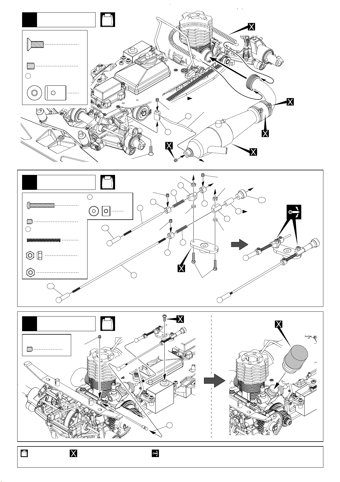
マフラー
Muffler
42
4 x 10mm
F/H Screw
サラビス
No.9, No.11
スプリング
Spring
1
4 x 4mm
Set Screw
171
セットビス
マフラーホルダー
Muffler Holder
リンケージ
Linkage
43
2.6 x 15mm
Screw
3 x 3mm
Set Screw
163
スロットルブレーキスプリング
Throttle Brake Spring
2.6mm
Nylon Nut
2.6mm
Nut
ビス
セットビス
ナイロンナット
ナット
164B
1
1
162
2
3
2
2
2
4x10mm
No.8, No.11
2mm
ストッパー
Stopper
164B
マフラーに合わせて曲げる。
Bend and adjust
4x4mm
171
2.6mm(Nylon)
3x3mm
163
162
159
3
3x3mm
172
197
2.6mm
to the muffler.
162
3x3mm
2.6mm(Nylon)
177
197
2.6mm
マフラージョイントパイプ
Muffler Joint Pipe
マフラー
Muffler
164C
燃料チューブを
カットして使用。
Cut off the fuel tube.
ストラップ
Strap
163
162
サーボホーン
157
Servo Horn
2.6x15mm
リンケージ
Linkage
44
3 x 3mm
Set Screw
セットビス
使用する袋詰。
Part bags used.
22
3x3mm
1
別購入品。
Must be purchased separately!
No.8, No.11
プロポに付属
Come with radio.
158
可動するように組立てる。
Ensure smooth non-binding movement while assembling.
エアークリーナー
Air Cleaner
Page 23

45
燃料チューブ
Fuel Tube
No.8
177
燃料チューブ
Fuel Tube
フロントダンパー
Front Shock
46
150
ダンパーカラー(A)
Shock Collar (A)
2.6mm
Nylon Nut
73
146
2.6mm
Washer
47
ナイロンナット
4.8mm
ボールエンド(中)
Ball End (Medium)
フロントピストン
Front Piston
2
ワッシャー
2
フロントダンパー
Front Shock
2
2
2
151
Cリング
C-ring
149
Oリング(青)
O-ring (Blue)
144
149
2
4
No.1, No.10
150
151
141B
2.6mm
2.6mm
145
146
142
73
143
148
141A
154
155
オイル
Oil
x2
No.1, No.10
使用する袋詰。
Part bags used.
フロント用(短)
For Front (Short)
2セット組立てる(例)。
x2
Assemble as many times as specified.
152
x2
23
Page 24

リヤダンパー
Rear Shock
48
150
ダンパーカラー(A)
Shock Collar (A)
2.6mm
Nylon Nut
72
147
2.6mm
Washer
49
ナイロンナット
4.8mm
ボールエンド(短)
Ball End (Short)
リヤピストン
Rear Piston
ワッシャー
リヤダンパー
Rear Shock
151
2
149
2
2
144
2
2
Cリング
C-ring
Oリング(青)
O-ring (Blue)
No.1, No.10
149
2
4
150
151
44
2.6mm
2.6mm
145
147
142
72
143
148
141A
154
155
オイル
Oil
x2
No.1, No.10
フロントダンパー
Front Shock
50
102
5.8mm
ボールスクリュー
Ball Screw
153
リヤ用(長)
For Rear (Long)
x2
No.10
2
使用する袋詰。
Part bags used.
24
102
フロントダンパー
Front Shock
2セット組立てる(例)。
x2
Assemble as many times as specified.
左右同じように組立てる。
Assemble left and right sides the same way.
Page 25

リヤダンパー
Rear Shock
51
102
5.8mm
ボールスクリュー
Ball Screw
No.10
2
102
リヤダンパー
Rear Shock
52
タイヤ
Wheels
No.2
20
< >フロント
< >Front
< >リヤ
< >Rear
21
x2
x2
ピッタリはめてからタイヤとホイールの
間に瞬間接着剤を流し接着する。
After fitting them together, pour instant
glue along the seam.
使用する袋詰。
Part bags used.
左右同じように組立てる。
Assemble left and right
sides the same way.
瞬間接着剤で接着する。
Apply instant glue
(CA glue, super glue).
2セット組立てる(例)。
x2
Assemble as many times
as specified.
別購入品。
Must be purchased
separately!
25
Page 26

53
タイヤ
Wheels
< >
フロント
< >
Front
< >リヤ
< >Rear
54
183
ボディピン
Body Pin
ボディ
Body
183
フロントタイヤ
Front Wheel
No.11
4
リヤスポイラー
Rear Wing
リヤタイヤ
Rear Wheel
183
使用する袋詰。 別購入品。
Part bags used.
26
ボディ
Body
183
Must be purchased separately!
Page 27

取扱いの注意 OPERATING YOUR MODEL SAFELY
事故やケガ等の危険防止のため、次のことを必ずお守りください。
In order to avoid accidents and personal injury, be sure to observe the following:
●燃料の蒸気、排気ガスは有害ですので、必ず屋外で取
扱ってください。
Since exhausts and fuel vapors are noxious to health,
use fuel only outdoors!
●ケガの恐れがあるので、回転部分に手や物を入れない
ようにしてください。
Keep hands and objects away from rotating engine
parts to avoid personal injury.
●エンジンは、停止後でも本体やマフラー周辺は高温に
なっているので、ヤケドに注意してください。
Because after running the engine, the engine and the
muffler are extremely hot, beware of getting burned!
●燃料は模型用グロー燃料を必ず使用してください。ガ
ソリンや灯油の使用は、火災等の事故の恐れがありま
す。絶対に使用しないでください。
Only use glow fuel for radio control models! Never use
gasoline or kerosene which might cause accidents
such as fires!
●燃料は引火性がありますので、火気のあるところや室
内では絶対に使用しないでください。また、空缶は火
中には投げ入れないでください。爆発の恐れがあります。
Because fuel is highly inflammable, never use fuel
indoors, near any source of heat, open flames or even
sparks! Do not dispose of an empty fuel can into a fire.
It might explode causing serious injury!
●燃料は間違って 飲んだり目に入ると有害です。万一
事故が起きた場合は、吐かせる、洗眼するなどをした
後すぐに医師の診察をうけてください。
Be particularly careful not to swallow fuel or to get fuel
into eyes! Nevertheless, should fuel be swallowed,
immediately induce vomiting and call a physician.
Should fuel get into eyes, thoroughly rinse the eyes
and seek medical advice.
●次のような時、場所では走行させないでください。思
わぬ事故の原因となります。
For accident prevention, do not run your model under
the following circumstsnces:
人が多い場所。
In place where many people gather.
家、学校、病院などの近く。
Near residential districts, schools and hospitals.
道路、線路、電線の近く。
Near roads, railroads, air corridors and electric lines.
同じバンドの無線操縦模型が近くにいる時。
Also make sure that nobody is using the same
frequency as you do at the same time!
プロポの電池が少ない時。
When the radio batteries are empty.
車の動きがおかしい時。
When the model's control or running behavior is
strange.
●燃料はキャップをしっかりしめ、幼児の手の届かない
冷暗所に保管してください。
Always store fuel in a safe place out of children's reach
with the cap shut tight! The place for storage should be
dark, cool and dry!
27
Page 28

EXPLODED VIEW
< >
一部パーツ販売していないパーツがあります。
Parts indentified only by key numbers are not sold individually!
リンケージ
Linkage
FM-314
43
OT-29
181
42
受信機ホルダー
Receiver Holder
FM-314
受信機ホルダー
Receiver Holder
OT-29
181
181
OT-29
181
OT-29
696770
FM-317B
UM-128
99
184
FM-375
116
FM-314
40
1701KP/KY
FM-313
37
88
プーリー
Pulley
(17T)
プーリー
Pulley (17T)
FM-330
38
167
FM-313
96888
167
C
FM-316
96888
FM-316
63
FM-330
92
FM-316
62
92
59 58
FM-315
52 53
A
FM-345
117
54
FM-315
51
FM-315
K
54
FM-315
FM-374
FM-344
J
D
FM-327
B
182
37
I
181
41
FM-313
FM-314
48
168
FM-339
W-0146G
165
OT-29
FM-314
C
96892
87
182
180
171 172
I
FM-325
86
FM-326
FM-377
187
FM-316
105
107
106
FM-374
164A
FM-373
96892
168
48
165
182
FD-65
D
FM-326
56
57
FM-314
W-0146G
FM-374
28
177
FM-311
FM-372
170
161
W-0147G
166
J
クラッチ
Clutch
177
F
E
ダンパー(フロント)
Shock (Front)
K
(L)
22
(R)
23
FM-308
FM-372
G
W-0147G
166
102
FM-336
FM-312
FM-372
160
86
35
36
34
FM-312
192
FM-314
39
E
H
G
83
FM-302(L)
FM-303(R)
FM-343-FU
112
FM-325
B
FM-335
100
FM-305
19
FM-322
14
13
73
101
FM-341
109
92653
120
UM-112
FM-320
81
FM-302(L)5
FM-303(R)6
FM-302(L)7
FM-303(R)8
FM-335
190
SPW-5
191
190
156
186
1295
1295
FM-370
FM-376
168
103
32
115
96892
FM-312
104
FM-343-RL
17
18
84
FM-337
FM-334
ギヤ
Gear
FM-338
FM-314
49
FM-337
103
15
16
UM-128
99
(L) FM-305
(R)
FM-323
FM-321
82
UM-112
73
UM-128
99
FM-337
103
(L)
1
(R)2
96892
168
85
FM-314
49
46
158
97
FM-310
26
96888
167
(L) FM-304
(R)
ギヤ
Gear
FM-328
89
FM-361
138
FM-360
FM-376
186
FM-314
49
FM-338
104
FM-300-2
FM-376
186
FM-318
75
FM-324
FM-338
104
FM-314
FM-333
140
137
139
135
96892
168
103
111
108
1902
169
49
FM-337
FM-342
FM-340-2.9
FM-314
46
95
96
135
139
137
140
96474
136
(L)
3
(R)4
FM-314
85
FM-338
104
FM-309
25
198
FM-360
96474
136
103
96892
168
186
FM-324
FM-342
111
FM-309
80
FM-301
FM-337
FM-314
49
104
FM-376
FM-310
27
H
FM-312
110
96892
168
FM-333
FM-363-44H
FM-359
134
FM-338
76
FM-312
33
96
95
FM-319
FM-316
66
94
185
94
FM-362-48L
79
FM-332
FM-328
201196
FM-329
91 90
FM-331
93
24
21
96892
168
FM-309
FM-307
リンケージ
Linkage
119
118
189
188
FM-346
FM-346
102
FM-336
FM-379
F
FM-378
FM-347
193 121
159
※FM-380のクラッチASSYもあります
FM-355
128
FM-357-20H
130
FM-356-16L
129
133
FM-348
122
FM-349
123
124
FM-349
123
FM-354
195
FM-352
126
133
1808
ダンパー
Shock
フロント
Front
FM-371
163
FM-371
163
167
FM-371
FD-65
164B
ダンパー
(リヤ)
Shock
(Rear)
FM-343
114
-RU
96888
プーリー
Pulley
(17T)
162
162
1808
クラッチ
Clutch
1901
FM-358
199194 131
96995
132
FM-350
FM-351
125
FM-353
127
1901
W-5105G
155
141A
148
143
142
146
145
144
149
150
151
W-5106
141A
W-5017
148
FM-364
143
142
FM-367
147
FM-366
FM-365
W-5107
149
150
151
FM-369-1.8
155
145
144
152 153
FM-368-1.8
FM-314
141B
W-5106
44
73 72
UM-112
162
164D
1808
197
リヤ
Rear
FD-65
177
FM-317
28
FM-315
50
FM-343-FL
113
W-0146G
A
165
11
12
FM-302(L)9
FM-303(R)
10
FM-302(L)
FM-303(R)
99
UM-128
20
FM-306
164B
FD-65
157
FM-371
FANTOM 2001© 1999 KYOSHO / 禁無断転載複製
29
Page 29

品番
No.
FM-300
-0
FM-300
-2
FM-301
FM-302
FM-303
FM-304
FM-305
FM-306
FM-307
FM-308
FM-309
FM-310
FM-311
FM-312
FM-313
FM-314
FM-315
FM-316
FM-317B
FM-318
FM-319
FM-320
FM-321
FM-322
FM-323
FM-324
FM-325
FM-326
FM-327
FM-328
FM-329
FM-330
FM-331
FM-332
FM-333
FM-334
FM-335
FM-336
パーツ名
Part Names
ナックルアーム0°
Knuckle Arm0°
ナックルアーム2°
Knuckle Arm2°
リヤハブ
Rear Hub
フロントサスアーム(左)
Front Suspension Arm (Left)
フロントサスアーム(右)
Front Suspension Arm (Right)
リヤアッパーアーム
Rear Upper Arm
リヤロアアーム
Rear Lower Arm
フロントホイール
Front Wheel
リヤホイール
Rear Wheel
フロントバルクヘッド
Front Bulkhead
リヤバルクヘッド
Rear Bulkhead
リヤバルクサポート
Rear Bulk Support
燃料タンク
Fuel Tank
リヤボディマウント
Rear Body Mount
センターバルク
Center Bulk
小物パーツセット
Small Parts Set
フロントバンパー
Front Bumper
プーリーセット
Pulley Set
サーボセイバー(10)
Servo Saver (10)
フロントワンタッチストッパー
Front One-touch Stopper
リヤワンタッチストッパー
Rear One-touch Stopper
フロントホイールシャフト
Front Wheel Shaft
リヤホイールシャフト
Rear Wheel Shaft
フロントスイングシャフト
Front Swingshaft
リヤスイングシャフト
Rear Swingshaft
3x20mm平行ピン
3x20mm Parallel Pin
フロントカップジョイント
Front Cup Joint
フロントシャフト
Front Shaft
ミドルシャフト
Middle Shaft
メインシャフト
Main Saft
リジッドアクスル
Rigid Axle
プーリーアダプター
Pulley Adapter
プーリー・ブレーキアダプター
Pulley / Brake Adapter
ブレーキディスク
Brake Disk
ブレーキパッド
Brake Pad
ブレーキカム
Brake Cam
ボディマウントスクリュー
Body Mount Screw
5.8mmボールスクリュー
5.8mm Ball Screw
スペアパーツ(1) SPARE PARTS (1)
内容(キーNo.と入数)
Quantity
オプションパーツ
Optional Parts
1 2 x 1
3 4 x 1
13
5 7 9
11 14
6 8
10 12 14
15 16
x 1
17 18
x 1
20
x 2
21
x 2
22 23
x 1
x 1
x 1
110
x 2
38
198
x 1
Eリング(E2.5)
E-ring (E2.5)
x 1
24 25
26 27
28
x 1
32 33 35
34
192
36
x 2
37
x 2
39 40 41 42 43
44 45 46 47 48
196
55
x 1
x 2
61 62 63 64
x 1
58 59
x 1 x 2
Cリング
C-ring
x 1
Eリング(E5)
E-ring (E5)
Cリング
x 1
C-ring
Eリング
E-ring
50 51
52 53 54
56 57 60
65 66
67 69 70
75
x 2
76
x 2
81
x 2
82
x 2
83
x 2
84
x 2
85
x 10
86
x 2
87
x 1 x 2
88
x 1
89
201
x 1
90 91
92
x 1
4x4mmセットビス
4x4mm Set Screw
4x4mmセットビス
93
x 1
4x4mm Set Screw
185
158
x 1
x 2
x 1
x 2
94
x 2
95 96
97
100 101
102
x 4
x 1
x 1
19
x 1
x 2
197
(E-7)
(E-7)
x 2
x 2
x 4
49
13
x 2
x 2
x 2
x 2
x10
x 1
x 2
x 1
x 1
x 1
★定価
500
500
500
500
500
450
550
500
600
600
500
350
1500
500
350
400
600
500
500
600
600
1400
1400
800
800
600
600
2200
300
1000
1000
450
1000
600
400
400
900
900
発送
手数料
200
(一律)
品番
No.
FM-337
FM-338
FM-339
FM-340
-2.6
FM-340
-2.9
FM-340
-3.2
FM-341
FM-342
FM-343
-FU
FM-343
-FL
FM-343
-RU
FM-343
-RL
FM-344
FM-345
FM-346
FM-347
FM-348
FM-349
FM-350
FM-351
FM-352
FM-353
FM-354
FM-355
FM-356
-16L
FM-356
-17L
FM-356
-18L
FM-357
-20H
FM-357
-21H
FM-357
-22H
FM-358
FM-359
FM-360
FM-361
FM-362
-48L
FM-362
-49L
FM-363
-44H
FM-363
-45H
Part Names
9mmボールスクリュー
9mm Ball Screw
10mmスクリューキャップ
10mm Screw Cap
フロントスタビライザーセット
Front Stabilizer Set
リヤスタビライザーバー(φ2.6)
Rear Stabilizer Bar (φ2.6)
リヤスタビライザーバー(φ2.9)
Rear Stabilizer Bar (φ2.9)
リヤスタビライザーバー(φ3.2)
Rear Stabilizer Bar (φ3.2)
5.8mm両ツバ付ボール
5.8mm Ball
ワンタッチスプリング
One-touch Spring
フロントアッパーサスシャフト
Front Upper Suspention Shaft
フロントロアーサスシャフト
Front Lower Suspention Shaft
リヤアッパーサスシャフト
Rear Upper Suspention Shaft
リヤロアーサスシャフト
Rear Lower Suspention Shaft
ロールバー
Roll Bar
メインシャシー
Main Chassis
エンジンマウント
Engine Mount
フライホイール
Flywheel Set
フライホイルナット
Flywheel Nut
ウエイトコーン
Weight Cone
クラッチディスク
Clutch Disk
クラッチシュー
Clutch Shoe
クラッチスプリング
Clutch Spring
スプリングナット
Spring Nut
スプリング受け
Spring Catch
クラッチベル
Clutch Bell
1速ギヤ(16T)
1st Gear (16T)
1速ギヤ(17T)
1st Gear (17T)
1速ギヤ(18T)
1st Gear (18T)
2速ギヤ(20T)
2nd Gear (20T)
2速ギヤ(21T)
2nd Gear (21T)
2速ギヤ(22T)
2nd Gear (22T)
ベルガイドワッシャー
Bell Guide Washer
1速ハウジング
1st Housing
2速シューセット
2nd Shoe Set
2速シューホルダー
2nd Shoe Holder
1速スパーギヤ(48T)
1st Spur Gear (48T)
1速スパーギヤ(49T)
1st Spur Gear (49T)
2速スパーギヤ(44T)
2nd Spur Gear (44T)
2速スパーギヤ(45T)
2nd Spur Gear (45T)
パーツ名
★FOR JAPANESE MARKET ONLY.
内容(キーNo.と入数)
Quantity
103
x 4
★定価
900
発送
手数料
200
(一律)
104
x 4
105 106 107
オプションパーツ
XX
Optional Parts
108
オプションパーツ
XX
Optional Parts
109
111
112
113
114
115
116
117
3x10mmキャップビス
3x10mm Cap Screw,,
121 193
122
123
124
125
126
127
195
128
129
XX
オプションパーツ
Optional Parts
オプションパーツ
XX
Optional Parts
XX
130
オプションパーツ
Optional Parts
オプションパーツ
XX
Optional Parts
131
x 1
x 1
x 1
x 5
x 10
x 2
x 2
x 2
x 2
x 1
x 1
118166 119
x4
x 1
x 1
x 3
x 1
x 1
x 1
x 1
x 1
x 1
x 1
x 1
x 1
x 1
x 1
x 1
5x0.1mmシム
x 1
5x0.1mm Shim
x 1
4x12mmサラビス
4x12mm F/H Screw
x1
5x0.5mmシム
5x0.5mm Shim
3x6mmサラビス
134
x 1
3x6mm F/H Screw
137135 139 140
x 2
2.6x12mmキャップビス
2.6x12mm Cap Screw
4x4mmセットビス
138
x 1
4x4mm Set Screw
XX
x 1
79
x 1
オプションパーツ
Optional Parts
XX
x 1
80
x 1
オプションパーツ
Optional Parts
x 4
x 2
x 3
x 2
x 1
400
1400
400
400
400
400
800
450
450
450
450
400
9800
,
,
1800
1800
450
400
450
1200
300
250
200
1200
700
700
700
700
700
700
250
1300
800
500
400
400
650
650
30
23
Page 30

品番
No.
FM-364
FM-365
FM-366
FM-367
FM-368
-1.7
FM-368
-1.8
FM-368
-1.9
FM-368
-2.0
FM-369
-1.7
FM-369
-1.8
FM-369
-1.9
FM-370
FM-371
FM-372
FM-373
FM-374
FM-375
FM-376
FM-377
FM-378
FM-379
FM-380
FM-381
F
FM-381
R
FM-382
FD-65
FM-29
OT-29
パーツ名
Part Names
ダンパーアジャストナット
Shock Adjustable Nut
ダンパーケース
Shock Case
ダンパーシャフト
Shock Shaft
ダンパーピストンセット
Shock Piston Set
フロントスプリング(φ1.7)
Front Spring (ø1.7)
フロントスプリング(φ1.8)
Front Spring (ø1.8)
フロントスプリング(φ1.9)
Front Spring (ø1.9)
フロントスプリング(φ2.0)
Front Spring (ø2.0)
リヤスプリング(φ1.7)
Rear Spring (ø1.7)
リヤスプリング(φ1.8)
Rear Spring (ø1.8)
リヤスプリング(φ1.9)
Rear Spring (ø1.9)
アジャスタブルロッド(L=68)
Adjustable Rod (L=68)
リンケージセット
Linkage Set
テンショナーセット
Tensionner Set
マフラーホルダーセット
Muffler Holder Set
燃料タンクポスト
Fuel Tank Post
メカプレート
Radio Plate
アクスルワッシャー(0.5)
Axle Washer (0.5)
フロントベルト 213
Front Belt 213
ミドルベルト420
Middle Belt 420
リヤベルト201
Rear Belt 201
クラッチASSY
Clutch Assembly
フロントダンパーASSY
Front Shock Assembly
リヤダンパーASSY
Rear Shock Assembly
デカール
Decal
リンケージセット
Linkage Set
ボディピン
Body Pin
Oリング(P3)
O-ring (P3)
スペアパーツ(2) SPARE PARTS (2)
内容(キーNo.と入数)
Quantity
142 143
x 2
144
x 2
2.6mmナイロンナット
2.6mm Nylon Nut
2.6mmワッシャー
2.6mm Washer
146 147
x 2
オプションパーツ
Optional Parts
XX
x 1
152
x 2
オプションパーツ
Optional Parts
オプションパーツ
XX
x 1
Optional Parts
オプションパーツ
XX
x 1
Optional Parts
153
x 2
オプションパーツ
XX
x 1
Optional Parts
156
x 2
157 159
x 1
160 161
x 1
3x3mmセットビス
3x3mm Set Screw
171 172
x 1
4x4mmセットビス
4x4mm Set Screw
165 180
x 2
3x6mmサラビス
3x6mm F/H Screw
184
x 1
186
x 10
187
x 1
188
x 1
189
x 1
121 122 124
129 130 131 132 193 195
3x12
キャップビス
3x12
Cap Screw
3x15
キャップビス
3x15
Cap Screw
5x0.1mmシム
5x0.1mm Shim
5x0.5mmシム
5x0.5mm Shim
141 142 143
149 150 151 155
2.6mm
ナイロンナット
2.6mm
Nylon Nut
2.6mm
ワッシャー
2.6mm
Washer
44
141 142
148 149 150 151 155
2.6mm
ナイロンナット
2.6mm
Nylon Nut
2.6mm
ワッシャー
2.6mm
Washer
デカール
Decal
164
x 1 set
183
x 10
181
x 10
145
x 2
163
x 2
170
x 2
Eリング(E4)
,
E-ring (E4)
,
4x10mmサラビス
,
4x10mm F/H Screw
,
182
x 4
x 4
125 126 127 128
x 1
x 1
133
x 1
123
x 4
x 2
144 145 146 148
x 2
x 2
x 2
143 144 145 147
x 2
x 2
x 2
x 1
x 2
x 1
x 2
x 3
x1
★定価
350
1800
500
500
500
500
500
500
500
500
500
650
300
1500
250
350
2800
350
800
700
900
8500
3200
3200
1000
1100
150
200
発送
手数料
200
(一律)
★FOR JAPANESE MARKET ONLY.
品番
No.
SPW-5
UM-112
UM-128
W-5017
W-5105G
W-5106
W-5107
1295
1700KP
1700KY
1701KP
1701KY
1705
1808
1901
92642
92653
96474
96995
1151
1168
1166
1394
96888
96892
W-0146
G
W-0147
G
キットの部品の一部にはスペアパーツとして販売していない物があります。
京商ではオプションパーツを販売していますのでお買い求めください。
Some of the parts included are not available as spare parts. Purchase
optional parts instead.
パーツ名
Part Names
アジャストロッドセット
Adjuster Rod Set
4.8mmボールエンド
4.8mm Ball End
4.8mmボールスタッド
4.8mm Ball Stud
プレッシャートップ
Shock Diaphragm
ダンパーキャップ
Shock End Cap
ダンパープラパーツ
Shock Plastic Parts
Oリングセット
O-ring Set
5.8mmボールエンド
5.8mm Ball End
蛍光ナイロンストラップ ピンク(S)
Fluorescent Nylon Strap Pink (S)
蛍光ナイロンストラップ イエロー(S)
Fluorescent Nylon Strap Yellow (S)
蛍光ナイロンストラップ ピンク(M)
Fluorescent Nylon Strap Pink (M)
蛍光ナイロンストラップ イエロー(M)
Fluorescent Nylon Strap Yellow (M)
アンテナパイプ
Antenna Pipe
ロッドストッパー
Rod Stopper
5x10x4mmベアリング
5x10x1mm Ball Bearing
5x8x2.5mmベアリング
5x8x2.5mm
Ball Bearing
サスシャフト
Suspension Shaft
5.8mmハードボールジョイント(3.0mm穴)
5.8mm Hard Ball Joint (w/3.0mm hole)
6x12x4mmベアリング
6x12x4mm Ball Bearing
5x10x4mm
5x10x4mm
スラストベアリング
Thrust Bearing
サラタッピングビス
TP Flat Head Screw
4x12mmサラビス
4x12mm Flat Head Screw
4x8mmセットビス(平先)
4x8mm Set Screw
2.6x18mmキャップビス
2.6x18mmCapScrew
Cリング(C11)
C-ring(C11)
6x13x5mmベアリング
5x13x5mm Ball Bearing
12x21x5mmベアリング
12x21x5mm
3mm
3mm
4mm
4mm
Ball Bearing
サラワッシャー金
Flat Head Washer(Gold)
サラワッシャー金
Flat Head Washer(Gold)
内容(キーNo.と入数)
Quantity
191
x 2
72 73
x 6
99
x 4
148
x 10
155
x 4
141
x 2
149
150 151
190
x 1
x 8
XX
x 1
XX
x 1
XX
x 1
XX
x 1
173
x 1
162
x 5
x 1
169
x 2
169
x 2
192
x 4 x 4
XX
120
x 2
136
x 2
132
x 1 set
x 4
x 2
Eリング(E2.5)
E-ring (E2.5)
4x8mm x 5
4x12mm x 5
x 10
XX
x 10
XX
x 4
XX
x 10
XX
167
x 2
XX
168
x 2
165
x 10
166
x 10
★定価
650
300
400
200
700
450
450
200
180
180
250
250
500
250
700
7001902
250
800
1000
800
200
200
200
2001196
200
700
1000
500
500
発送
手数料
200
(一律)
31
Page 31

★
★
★
★
★
品番
No.
W5109
1776
1829
1948
56410
57507
57507P
57507G
57507Y
57623
57430
57439
PC7007
80411
96411
96981
39308
58403R
58403B
58420-15
58420-20
58420-25
71312
72506
80311
87651
87822
92515
92654
94402
96405
96625
96642
96607
96611
96608
96612
96609
96613
32
パーツ名
Part Names
ショックオイルデカール
Damper Oil Decal
ピットボックス
Pit Box
ラウンドカッター&サンダー
Hobby Shears &Sander
エアクリーナーオイル
Air Cleaner Oil
プレシジョンキャンバーゲージ
Precision Camber Gauge
Team燃料シリコンチューブ(クリア)
Team Silicone Fuel Tube(Clear)
Team燃料シリコンチューブ(ピンク)
Team Silicone Fuel Tube(Pink)
Team燃料シリコンチューブ(グリーン)
Team Silicone Fuel Tube(Green)
Team燃料シリコンチューブ(イエロー)
Team Silicone Fuel Tube(Yellow)
アローズリアスポイラー1/8用
Arrows Rear Spoiler
PARISロニーグリス(1/2oz)
ダストクリーナー
Dust Creaner
エアフィルター
Air Filter
ボールポイント六角レンチ5mm
Ball-Point Hex Wrench 5mm
ワンタッチプラグヒートセット
One-Touch Plug Heater Set
モリブデングリススプレー
Molybdenum Coat
燃料フィルター(M)
Fuel Filter (M)
Teamマルチボックス(レッド)
Team Multi Box(Red)
Teamマルチボックス(ブラック)
Team Multi Box
六角ドライバー1.5mm
Hex Wrench 1.5mm
六角ドライバー2.0mm
Hex Wrench 2mm
六角ドライバー2.5mm
Hex Wrench 2.5mm
6V‑600mAhニカドバッテリー
6V-600mAh NiCd-Battery
マルチチャージャーIII
Multi Charger III
スペシャルテーパーリーマー
Taper Reamer
メンテナンススタンド
Maintenance Stand
TeamKYOSHOプロポバッグ
Team KYOSHO Transmitter Bag
耐熱
マフラージョイントパイプ
Muffler Joint Pipe
5.8mmハードボールジョイント(3.2)
5.8mm Hard Ball Joint(3.2)
ロックタイト(中強度)
Locktite (Medium Strength)
パワークリーナー
Power Cleaner
SPベアリングリキッド
SP Bearing Liquid
シムセット(4×6mm)
4×6mm Sim Set
シリコンオイル#400
Silicone Oil #400
シリコンオイル#450
Silicone Oil #450
シリコンオイル#500
Silicone Oil #500
シリコンオイル#550
Silicone Oil #550
シリコンオイル#600
Silicone Oil #600
シリコンオイル#700
Silicone Oil #700
オプションパーツ OPTION PARTS
内容(キーNo.と入数)
Quantity
5色のオイルNo.デカールで
誤使用防止
サイズ/420×240×330mm
曲線部分のボディカットも容易
視認性にも優れたシリコン製
燃料チューブ
視認性にも優れたシリコン製
燃料チューブ
視認性にも優れたシリコン製
燃料チューブ
視認性にも優れたシリコン製
燃料チューブ
リアスポイラー一式
ニカドバッテリー、ACチャージャー
入り
収納性にも優れたボックス
収納性にも優れたボックス
受信機用ニカドバッテリー
ボディのマウント用穴開けに
便利
作業性アップの専用スタンド
耐熱性に優れる
ネジのゆるみ防止剤
ベアリング本来の性能を発揮
0.1、0.2、0.3 各10枚入り
ダンパーセッティング用
ダンパーセッティング用
ダンパーセッティング用
ダンパーセッティング用
キット標準
ダンパーセッティング用
★定価
500
6800
1000
1000
1400
400
400
400
400
1000
600
1000
1200
850
4800
1600
1000
9800
9800
700
700
700
3800
4800
1800
1800
2800
1000
800
900
800
1000
450
600
600
600
600
600
600
発送
手数料
200
(一律)
★
★
品番
No.
96610
96422
607002
607011
622001
622002
622003
622004
622011
622012
622013
622014
622021
622022
622023
622024
622031
622032
622033
622034
622041
622042
622043
622044
622051
622052
622053
622054
622061
622062
622063
622064
622071
622072
622073
622074
FMW-1
38403
39471
603001
603002L
Part Names
シリコンオイル#800
Silicone Oil #800
クイックフュールポンプ500cc
Quick Fuel Pump 500cc
トルネードフュエルSP
Tornade Fuel 2.5L
トルネードアフターランオイル
Tornade After Run Oil
フロントタイヤ スタンダード
TYRE (F) Standard 30°
フロントタイヤ スタンダード35°
TYRE (F) Standard 35°
フロントタイヤ スタンダード37°
TYRE (F) Standard 37°
フロントタイヤ スタンダード40°
TYRE (F) Standard 40°
フロントタイヤ マルチ30°
TYRE (F) Multi 30°
フロントタイヤ マルチ35°
TYRE (F) Multi 35°
フロントタイヤ マルチ37°
TYRE (F) Multi 37°
フロントタイヤ マルチ40°
TYRE (F) Multi 40°
リヤタイヤ スタンダード30°
TYRE (R) Standard 30°
リヤタイヤ スタンダード35°
TYRE (R) Standard 35°
リヤタイヤ スタンダード37°
TYRE (R) Standard 37°
リヤタイヤ スタンダード40°
TYRE (R) Standard 40°
リヤタイヤ マルチ30°
TYRE (R) Multi 30°
リヤタイヤ マルチ35°
TYRE (R) Multi 35°
リヤタイヤ マルチ37°
TYRE (R) Multi 37°
リヤタイヤ マルチ40°
TYRE (R) Multi 40°
フロントタイヤ スタンダード30°
TYRE (F) Standard 30°
フロントタイヤ スタンダード35°
TYRE (F) Standard 35°
フロントタイヤ スタンダード37°
TYRE (F) Standard 37°
フロントタイヤ スタンダード40°
TYRE (F) Standard 40°
フロントタイヤ マルチ30°
TYRE (F) Multi 30°
フロントタイヤ マルチ35°
TYRE (F) Multi 35°
フロントタイヤ マルチ37°
TYRE (F) Multi 37°
フロントタイヤ マルチ40°
TYRE (F) Multi 40°
リヤタイヤ スタンダード30°
TYRE (R) Standard 30°
リヤタイヤ スタンダード35°
TYRE (R) Standard 35°
リヤタイヤ スタンダード37°
TYRE (R) Standard 37°
リヤタイヤ スタンダード40°
TYRE (R) Standard 40°
リヤタイヤ マルチ30°
TYRE (R) Multi 30°
リヤタイヤ マルチ35°
TYRE (R) Multi 35°
リヤタイヤ マルチ37°
TYRE (R) Multi 37°
リヤタイヤ マルチ40°
TYRE (R) Multi 40°
SP リヤサスホルダー(7mm)
SP Rear Sus Holder(7mm)
ポルシェ962エアロ(1/8用)
Porche 962 Aero (1/8)
VDS ローラ(1/8用)
VDS Lola (1/8)
スーパーポルシェ962(1/8用)
Super Porche 962 (1/8)
VDS ローラSP(1/8用ライト)
VDS Lola SP (1/8 Light)
パーツ名
★FOR JAPANESE MARKET ONLY.
内容(キーNo.と入数)
Quantity
ダンパーセッティング用
スピーディーな給油が可能
★定価
600
1200
3600
600
30°
2本入り
2本入り
2本入り
2本入り
2本入り
2本入り
2本入り
2本入り
2本入り
2本入り
2本入り
2本入り
2本入り
2本入り
2本入り
2本入り
ホイル接着、成型済み
ホイル接着、成型済み
ホイル接着、成型済み
ホイル接着、成型済み
ホイル接着、成型済み
ホイル接着、成型済み
ホイル接着、成型済み
ホイル接着、成型済み
ホイル接着、成型済み
ホイル接着、成型済み
ホイル接着、成型済み
ホイル接着、成型済み
ホイル接着、成型済み
ホイル接着、成型済み
ホイル接着、成型済み
ホイル接着、成型済み
アルミ製、高剛性
1コ入、2コ必要
2200
2200
2200
2200
2600
2600
2600
2600
3000
3000
3000
3000
3400
3400
3400
3400
3000
3000
3000
3000
3400
3400
3400
3400
3800
3800
3800
3800
4200
4200
4200
4200
2500
3000
3000
3000
3000
発送
手数料
200
(一律)
Page 32

SCREW ・ NUT etc.ビス・ナット類
品番
No.
1101
1102
1103
1104
1105
1106
1110
1111
1112
1113
1114
1115
1118
1119
1120
1121
1122
1123
1124
1125
1126
1127
1128
1129
1130
1131
サイズ(mm)
Size (mm)
ナベビス
Round Head Screw
2x6・2x8・2x10・2x15 5 each 10 each
2.6x8・2.6x10・2.6x12・2.6x14
3x4・3x6・3x8・3x10・3 x12
3x14・3x16・3x18・3x20
4x6・4x8・4x10・4x12
3x22・3x24・3x26・3x28
バインドビス
Bind Screw
2.6x4・2.6x6・2.6x8・2.6x12
3x4・3x6・3x8・3x10・3x12
3x14・3x16・3x18・3x20
4x6・4x8・4x10・4x12
3x22・3x25・3x28・3x30
4x15・4x18・4x20・4x22
サラビス
Flat Head Screw
2.6x8・2.6x10・2.6x12・2.6x14
3x6・3x8・3x10・3x12
3x14・3x16・3x18・3x20
4x8・4x10・4x15・4x20
3x22・3x24・3x26・3x28
3x30・3x32・3x34・3x35
キャップビス
Cap Screw
2x8・2x10・2x12・2x14
2.6x8・2.6x10・2.6x12・2.6x14
3x8・3x10・3x12・3x14
3x15・3x16・3x18・3x20
3x25・3x30・3x35・3x40
4x10・4x15・4x20
4x25・4x28・4x30
4x35・4x40・4x45
入数(各)
QUANTITY
●200 ●200
5 each
5 each
5 each
5 each
5 each
●200
5 each
5 each
5 each
5 each
5 each
5 each
●200
5 each
5 each
5 each
5 each
5 each
5 each
●200
2 each
2 each
2 each
2 each
2 each
2 each
2 each
2 each
品番
No.
1132
1133
1134
1135
1136
1137
1140
1141
1142
1143
1147
1148
1149
1150
1153
1154
1157
1160
1161
1162
1163
1164
1165 3x20・3x25 3 each
サイズ(mm)
Size (mm)
ナベタッピングビス
Round Head Self-Tapping Screw
2x4・2x6・2x8・2x10 5 each
2.6x6・2.6x8・2.6x10・2.6x12
3x6・3x8・3x10・3x12・3x14
3x15・3x16・3x18・3x20
3x25・3x30・3x35
2.6x14・2.6x15・2.6x16・2.6x18
バインドタッピングビス
Bind Self-Tapping Screw
2.6x6・2.6x8・2.6x10・2.6x12
3x6・3x8・3x10・3x12・3x14
3x15・3x16・3x18・3x20
4x10・4x15・4x18
サラタッピングビス
Flat Head Self-Tapping Screw
2.6x6・2.6x8・2.6x10・2.6x12
3x6・3x8・3x10・3x12・3x14
3x15・3x16・3x18・3x20
4x15・4x20・4x25
フランジ付キャップビス
Flanged Cap Screw
3x6・3x8・3x10
4x8・4x10・4x12
サラ小丸ビス
Oval Head Screw
2x8・2x10
セットビス
Set Screw
3x6・3x12・3x14・3x16
3x3・3x4・3x5・3x10
4x4・4x5・4x8・4x12
5x4・5x5・5x6
5x30・5x40
入数(各)
QUANTITY
●200
5 each
5 each
5 each
5 each
5 each
●200
5 each
5 each
5 each
5 each
●200
5 each
5 each
5 each
5 each
●200
2 each
2 each
●200
10 each
●200
3 each
3 each
3 each
3 each
3 each
● FOR JAPANESE MARKET ONLY.
品番
No.
1171
2mm・2.6mm
1172
3mm・4mm
1174
3mm
1175
4mm
1177
2.6mm
1178
3mm
1179
4mm
1180
4mm
1185
2mm・2.6mm・3mm
1186
4mm・5mm
1380
E1.5
1381
E2.0
1382
E2.5
1383
E3.0
1384
E4.0
1385
E5.0
1386
E6.0
1387
E7.0
1390
E10.0
ここに明記された以外のビス、ナット等は
『ユーザー相談室』にお問い合わせください。
径
¯
ナット
Nut
フランジ付ナット
Flanged Nut
ナイロンナット
Nylon Nut
フランジ付ナイロンナット
Flanged Nylon Nut
ワッシャー
Washer
Eリング
E-Clips
入数(各)
QUANTITY
10 each
●200
10 pcs
10 pcs
●200
5 pcs
5 pcs
5 pcs
●200
5 pcs
●200
10 each
10 each
●150
10 pcs
10 pcs
10 pcs
10 pcs
10 pcs
10 pcs
10 pcs
6 pcs
6 pcs
33
Page 33

THE FINEST RADIO CONTROL MODELS
R
メーカー指定の純正部品を使用して
安全にR/Cを楽しみましょう。
京商株式会社
〒243-0034 神奈川県厚木市船子153
●ユ−ザ−相談室直通 TEL.046-229-4115
お問い合わせは:月曜〜金曜(祝祭日を除く) 10:00〜18:00
PRINTED IN JAPAN63010006-2
 Loading...