

Page 1
Instruction Manual
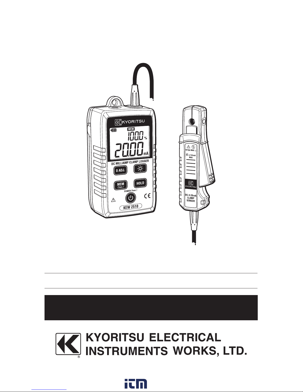
KEW 2510
DC Milliamp Clamp Logger
www. .com
information@itm.com1.800.561.8187
Page 2

Contents
1.Safety warnings
……………………………………………………
1
2
.
Features
……………………………………………………………
4
3
.
Specifications
……………………………………………………
4
4
.
Instrument layout
…………………………………………………
6
5
.
Preparation
…………………………………………………………
6
6
.
Getting started
……………………………………………………
7
6-1
Zero-adjustment
…………………………………………
7
6-2
Measurement
……………………………………………
7
7
.
Other functions
……………………………………………………
8
7-1
Data Hold function
………………………………………
8
7-2
Auto-power-off function
…………………………………
8
7-3
Backlight & LED light
……………………………………
9
7-4
Analog output function
…………………………………
9
7-5
Memory function
…………………………………………
9
8
.
Communication function/ Application software
……………
10
9
.
AC adapter power supply
……………………………………
11
9-1
How to use AC adapter
………………………………
11
9-2
Specifications of AC adapter
………………………
11
10
.
Battery replacement
…………………………………………
12
www. .com
information@itm.com1.800.561.8187
Page 3

1
1.Safety warnings
○
This instrument has been designed, manufactured and tested
according to IEC
61010
: Safety requirements for Electronic
measuring apparatus, and delivered in the best condition after
passing quality control tests. This instruction manual contains
warnings and safety rules which have to be observed by the user to
ensure safe operation of the instrument and to maintain it in safe
c o n d i t i o n . T h e r e fo r e , re a d t h r o u g h t h e s e o p e r a t i n g i n s t r u c t i o n s b e f o r e
starting to use the instrument.
#WARNING
●
Read through and understand the instructions contained in this
manual before starting to use the instrument.
●
Keep the manual at hand to enable quick reference whenever
necessary.
●
The instrument is to be used only in its intended applications.
●
Understand and follow all the safety instructions contained in the
manual.
It is essential that the above instructions are adhered to. Failure to
follow the above instructions may cause injury, instrument damage
and/or damage to equipment under test. Kyoritsu is by no means
liable fo r any damage resulting fro m th e instrument in contradiction to
these cautionary notes.
○
The symbol # indicated on the instrument means that the user must
refer to the related parts in the manual for safe operation of the
instrument. It is essential to read the instructions wherever the
symbol appears in the manual.
#DANGER :
is reserved for conditions and actions that are likely
to cause serious or fatal injury.
#WARNING:
is reserved for conditions and actions that can
cause serious or fatal injury.
#CAUTION:
is reserved for conditions and actions that can
cause injury or instrument damage.
www. .com
information@itm.com1.800.561.8187
Page 4

2
Please refer to the following explanation of the symbols used on the
instrument and in this manual.
#
User must refe r to th e e xplanations in the inst ruct ion manual .
Application around hazardous live conductors is NOT
permitted.
Crossed-out wheel bin symbol (according to WEEE
Directive:
2002/96
/EC) indicating that this electrical
product may not be treated as household waste, but that it
must be collected and treated separately.
#DANGER
●
Never make measurements on a circuit in which earth potentials of
45
Vpk or higher exist.
●
Do not attempt to make measurements in the presence of
flammable gasses. Otherwise, th e use of the instrume nt may cause
sparking, which can lead to an explosion.
● N ev er attempt to use th e in str ume nt if its sur fa c e or yo ur ha n d is wet.
●
Do not exc eed th e maximum a llowa ble in p ut of any me asu ring range.
●
Neve r open th e bat tery co mp artment c over du rin g a meas urement.
●
Neve r attempt to make any measurements if t he clamp sensor an d /
or the instrument has any structural abnormality, such as a crack,
or if the cover is not securely attached.
●
Do not measure AC currents.
●
The instrument should be used only in its intended applications or
conditions. Otherwise, safety functions equipped with the
in st ru ment do not wo rk, and ins tr ument da ma ge or se riou s p ers ona l
injury may be caused.
●
Keep your hands and fingers behind the safety barrier on clamp
sensor during a measurement.
#WARNING
●
Never attempt to make any measurements if any abnormal
conditions, such as a broken cover or exposed metal parts are
present on the instrument and clamp sensor.
● Do not install substitute parts or make any modifications to the
instru me n t . R e t u r n t h e i n s t r u m e n t to you r l o c a l K YO R I T S U distr i bu to r
for repair or re-calibration in case of suspected faulty operation.
●
Do not try to replace batteries if the surface of the instrument is wet.
●
Ensure that the Clamp sensor is disconnected from the object
u n d e r test, a nd t h at th e in stru m e nt is p owere d of f w h e n openin g t h e
battery compartment cover for battery replacement.
● Ra dio w aves at Blu etooth com mu nication may affect t he op eratio ns of
medical electronic devices. Special care should be taken when using
B l u e t o o t h c o m m u n i c a t i o n i n t h e a r e a s w h e r e s u c h d e v i c e s a r e p r e s e n t .
www. .com
information@itm.com1.800.561.8187
Page 5

3
#CAUTION
●
Do not expose the instrument to direct sunlight, high temperature,
humidity or dew.
●
This instrument is not water/ dust-proof. Do not use it in a dusty
environment or where it will get wet.
●
Always power off the instrument after use. Remove batteries if the
instrumentis to be stored and will not be in use for a long period.
●
Use a damp cloth with neutral detergent or water for cleaning the
instrument. Do not use abrasives or solvents.
○
Measurement Category
To ensure safe operation of measuring instruments, IEC
61010
establishes safety standards for various electrical environments,
categorized as O to CAT IV, and called measurement categories.
Higher-numbered categories correspond to electrical environments
with greater momentary energy, so a measuring instrument designed
for CAT III environments can endure greater momentary energy than
one designed for CAT II.
KEW
2510
i s C AT O ra ted. D o n o t u s e in CAT I I , I I I o r IV e nvi ronment s .
O:
Circuits which are not directly connected to the mains power
supply.
CAT
Ⅱ:
Electrical circuits of equipment connected to an AC
electrical outlet by a power cord.
CAT
Ⅲ:
Primary electrical circuits of the equipment connected
directly to the distribution panel, and feeders from the
distribution panel to outlets.
CAT
Ⅳ:
The circuit from the service drop to the service entrance,
a n d to th e p o w e r m e ter a n d pri mary o ver- c u r r e n t p r ote c t ion
device (distribution panel).
O: Device which is
not directly
connected to the
mains power supply
www. .com
information@itm.com1.800.561.8187
Page 6

4
2.Features
●
Measure 4 to
20
mA instrumentation signal
●
Measure 0 to
100
mA DC current without breaking the loop
●
LED light for illuminating the measurement spot
●
Auto-power-off function
●
Percentage (%) span
●
Analog output function to output the measured results to a recorder
or digital multi-meter
●
Data hold function
●
Memory function stores up to
192000
records
●
Transfer data to PC via BluetoothⓇ
●
AC adapter supplied as a standard accessory
3.Specifications
●
Measuring range and accuracy (
23ºC±5ºC, RH
75
% or less)
(1)DC current (auto-range)
Range Display range
Guaranteed accuracy
Accuracy Condition
20
mA0.
00
~±21.
49
mA0.
00
~±
21.49
mA±0.2
%rdg±5
dgt
After Zeroadjustment
d e s c r i b e d a t
clause 6-1.
100
mA±21.0
~±
126.0
mA±21.0
~±
120.0
mA±1.0
%rdg±5
dgt
※
Cautions for a long period of measurement or recording:
・
A b o u t
10
min of warm up is required right after powering on the
instrument.
・
Temperature coefficient defined later in this manual and also zero
point fl u ctu a tio n – abo u t
20
co u n ts wit h a 10º
C ris e in t emper atu r e
- should be taken into consideration if ambient temperature varies
during a recording.
(2)Analog output function
Output DC voltage (10mV/mA) corresponding to a reading.
Range Display range Output voltage Accuracy
20
mA
0.00
~±
21.49
mA0.0~±
214.9
mV
A c c u r a c y s p e c i f i e d a t c l a u s e
3 (1
) plus (±0.5
mV)
100
mA
±
21.0
~±
126.0
mA±210
~±
1260
mV
A c c u r a c y s p e c i f i e d a t c l a u s e
3 (1
) plus (±3
mV)
※
130 0
m V i s o u t p u t w h e n t h e d i s p l a y s h o w s ”OL”. ( -
130 0
m V f o r“-OL”.)
See clause 6 for explanations on OL display.
※
Output impedance : approx. 5k
Ω
www. .com
information@itm.com1.800.561.8187
Page 7

5
●
Applicable standards
IEC
61010-1
Measurement CAT O (Other), Pollution degree
2
IEC
61010-2-032
IEC
61326-1
(EMC)
IEC
60529
IP
40
EN
50581
RoHS Directive
●
Display Liquid crystal display
(See also
“4. Instrument layout”.)
●
Refresh rate Approx. once/ 0.6 second
●
Sampling rate
Approx. 4ms
(Averaging data in about
0.6
sec.)
●
Location for use In-door use, altitude
2000
m or less
●
Operating temperature -10
to +
50ºC RH
85
% or less (no condensation)
& humidity
When using AC adapter:
0
to +
40ºC RH
85
% or less (no condensation)
●
Storage temperature -20
to +
60ºC RH
85
% or less (no condensation)
& humidity
●
Power source Size AA battery x 4 pcs
(Alkaline LR
6
is recommended.)
External supply (AC adapter MODEL
8320
)
●
Battery life
Approx.
50
h o u r s c o n t i n u o u s w i t h a l k a l i n e b a t t e r i e s
(w i t h B a c klight, LE D l ight a n d Bl u e t o o t h Ⓡfe a t u re O FF )
●
Auto-power-off
Powe r off fu n ctio n op e rates in 10 min af te r th e last
switch operation. This function is disabled when a
cord is being connected to the OUTPUT terminal
and me mo ry fu nction to reco rd resu lts is activate d .
●
Temperature
0.1
x specified accuracy/ ºC
coefficient (above
28ºC or below 18º
C)
●
Withstand voltage
2210
V AC for 5 sec
(between electrical circuit and enclosure)
●
Insulation resistance 100MΩ
or more/
1000
V
(between electrical circuit and enclosure)
●
Rated voltage
42
Vpk (circuit – ground)
●
Conductor size Max. Ф6
mm
●
Dimension
111
(L) x
61
(W) x
46
(D)mm
●
Weight Approx.
310
g (including batteries)
●
Accessory Soft case MODEL
9096
・・・・・・・・・・・・・・・・・1 pce
Size AA Alkaline battery LR
6
・・・・・・・・・・・4 pcs
Instruction manual
・・・・・・・・・・・・・・・・・・・・・・・1 pce
AC adapter MODEL
8320
・・・・・・・・・・・・・・・1 pce
CD-ROM (KEW Windows for
2510)・・・・1 pce
Software installation manual
・・・・・・・・・・・・1 pce
●
Optional accessory
Analog output cord MODEL
7256
www. .com
information@itm.com1.800.561.8187
Page 8

6
4.Instrument layout
5.Preparation
(1)
Power on the instrument, and then check smooth opening and
closing of clamp sensor.
(2)
When operating the instrument with battery, always check the
battery voltage, without connecting the AC adapter, before
starting to use the instrument. Battery mark doesn’t appear
rega rdless of battery status while the AC adapter is connected to
the instrument.
Press Powe r button and get the instrume nt star te d . If emp ty ba ttery
indicator
“ ”
appears in the LCD, replace the batteries with new
ones according to“9
. Battery replacement”in this manual.
(3)
Ensure that the Data hold function is not in active status.
Zero adjustment
(0 ADJ.) button
Memory
(MEM) button
Light button
Data hold button
Power button
Trigger
LCD
Analog output
terminal
Transformer
jaws
Polarity mark
Main unit
Clamp sensor
Battery mark
Hold mark
Zero adj. mark
Sub display
Main display
LCD
LED light
Barrier
Bluetooth®mark
Memory mark
External supply
connection terminal
www. .com
information@itm.com1.800.561.8187
Page 9

7
6.Getting started
#WARNING
●
Do not clamp onto an un-insulated conductor.
●
A lwa y s u s e a n a log o u t p u t c o rd M O D E L
7256
, s p e c ially d e s igned to
this instrument, when using analog output function.
#DANGER
●
Keep your fingers and hands behind the barrier during a
measurement.
#CAUTION
●
Dirty clamp sensor may cause false reading. Confirm that clamp
sensors are clean before making a measurement.
●
Wh e n p e rforming ze ro ad ju stment in orde r to minimize the influ e nce
of electromagnetic waves, bring a clamp sensor close to the
conductor under test.
●
Take sufficient care not to apply sh ock, vibration or excessive fo rce
whenopening and closing the clamp sensor. Otherwise, accurate
results may not be obtained. Please open and close the sensor
lightly.
6−1Zero-adjustment
Perform zero adjustment prior to starting a measurement.
With the transformer jaws closed and without clamping them onto a
conductor, press the Zero ADJ. button.
Then the Zero adjustment mark“ ”is shown on the LCD for
about
1
sec.
Zero ADJ. button is disabled while;
・
the LCD showing“OL”, or
・
recording results with memory function.
6−2Measurement
Press the trigger to open the transformer jaws and clamp them onto a
conductor under test and take the
reading shown in main display area.
(See the figure below.)
• When a current flows in the same
directio n as indicat ed by the a rrow
mark on the jaws, the polarity of
the reading is positive and vice
versa.
correct
wrong
www. .com
information@itm.com1.800.561.8187
Page 10

8
※
% (Span) display
T h e s u b di s pla y s h o w s p e r ce nta g e v alu e as t h e b a sis of 4mA is 0% a n d
20
mA is
100
%. (at
20
mA range only)
The table at the right shows the
relationship between %(Span)
v a l u e s a n d m e a s u r e d v a l u e s (m A ) .
The percentage value is
calculated based on the
following formula, assuming the
measured value as X.
Percenta ge = (
│X│
- 4.
00)×6.
25
Measured
values (mA
)
Percentage
display (%)
-
20.00 100.0
0
.
00
-
25.0
2
.
00
-
12.5
4
.
00 0.0
12
.
00 50.0
20
.
00 100.0
100
.
0
---
※
Over-limit indication
When a measured value exceeds the max display range (
126.0
mA),
"OL" or “-OL” (for negative values) is indicated on the display.
When t h e r a n ge reaches to
100
mA , b a rs (-- -) a re dis p lay e d i n ste a d of
percentage values.
7.Other functions
7−1DataHoldfunction
This is a function to freeze the measured value on the display. Press
the Data hold button once to freeze the reading. The reading will be
held regardless of subsequent va riation in input. The Data hold mark“
"is indicated on the display while the instrument is in the Data
Hold mode. To exit Data Hold mode, press the Data hold button again.
7−2Auto-power-offfunction
The instrument automatically powers off about 10 min after the last
operation. This function is disabled if the cord is being connected to
the analog output terminal or while recording measured data with
memory function.
Todisablethisfunction:
Hold down the Data hold button while powering on the instrument.
The LCD shows “P.oFF” for about 1 sec immediately after
powering on the instrument. To restore this function, power off once
and power on again.
www. .com
information@itm.com1.800.561.8187
Page 11

9
7−3Backlight&LEDlight
Press the Light button to turn on/ off the LED light and LCD
backlight. These lights automatically turn off after two minutes. To
disable the automatic light timeout, hold down the Light button while
powering on the instrument. The LCD shows “L.oFF” for about 1
sec immediately after powering on the instrument. To restore
automatic light timeout, power off once and power on again.
7−4Analogoutputfunction
DC voltage signal corresponding to the measured result is output
from the analog output terminal. (10mV/mA) It can be checked on a
re corder or a digital mu lti-meter conn e cted to th e ins trume nt by u sing
MODEL
7256
ou tpu t cord.
※
When connecting the
analog output cord to
the instrument, the subdisplay shows “OUT”
for 1 sec.
7−5Memoryfunction
Store measured values in the internal memory of KEW
2510
. Hold
down the Memory button 1 sec or longer to start recording. Another
long press will stop the recording. The mark keeps blinking on
the LC D during a r ecord ing. Powe r bu t ton d o esn’t w ork in th is p eriod .
※
Max number of records :
192000
※
R e c o r d i n g i n t e r v a l : 1/5/10/
30/60
s e c .
Use the special application software to
change the setting of recording
interval. Default setting is
60
sec.
Checking recording interval and
number of stored results :
Press the Memory button to show the
c u r re n tly sele cted re c o r d i n g i nterval o n
the main display and number of stored record is on the sub display
for 1 sec.
e.g.
100
results stored with
recording interval of 1 sec.:
Digital multi-meter
or recorder
Analog output cord
MODEL7256
Number of records
Recording interval
Recording
interval
Max recording
period
1
sec
53
hours
5
sec
11
days
10
sec
22
days
30
sec
66
days
60
sec
133
days
www. .com
information@itm.com1.800.561.8187
Page 12

10
※
Wh en number of reco rd s exce eds
10000
, th e sub display doesn’t
give numerical indication but just shows“>
9999”.
※
A short press, 1 sec or less, displays the pre -set recording interval
and number of records. Do not press the button 1 sec or longer for
confirmation, otherwise recording will start/ end.
※
Record ing sto p s when n u mber of re c o rds reaches to t h e u p per li mit
of
192000
. Recorded data is secured even when a recording is
interrupted by the exhausted batteries or when the instrument is
powered off for battery replacement.
※
When starting a new recording, the previous recorded data will be
deleted. Use the special application software and download the
recorded data to your PC.
※
When making measurements for a long period of time :
・
leave the instrument for the warm-up period of several tens of
minutes after powering it on, and then start a recording.
・
readin g s w ill v a r y w h e n t h e ambi e nt tempera t u r e c h an ges. I n t h is
case, the temperature coefficients specified at clause 3 and
flu c t u a ti o n s a t z e r o ( a b o u t
20
c o u n t s fl u c t u a te w h e n t e m p e r a t u r e
changes by 10º
C) should be taken into consideration.
8.
Communication function/ Application software
●
Interface
Communication method: Bluetooth® Ver2.1+EDR Class
2
Compliant profile : SPP
●
System requirements
OS (Operation System)
: F o r t h e s u p p o r t e d O S , p l e a s e c h e c k t h e v e r s i o n
label on the CD case or visit our homepage.
Memory
: 1Gbyte or more
Display
:
1024
x
768
dots,
65536
colors or more
HDD
: 1Gbyte or more (including Framework)
.NET Framework
: 3.5 or later
●
Trademark
・
Win d owsⓇis a r e gis tered t ra d e m a r k o f M icrosoft in th e Unit e d States.
・
BluetoothⓇis a registered trademark of Bluetooth SIG.
www. .com
information@itm.com1.800.561.8187
Page 13

11
●
Application software (KEW Windows for
2510
)
This special application enables data download, analysis and
instrument configuration via PC. Refer to the supplied software
installation manual and install the application in your PC. For the
details, see the manual for
“
KEW Windows for
2510
”
by clicking
the icon to be created in the desktop after installation.
BluetoothⓇmark“ ”displayed on the instrument indicates the
instrument and the installed application software have been
connected.
9.AC adapter power supply
#WARNING
●
Use only MODEL
8320
AC adapter with this instrument.
●
Confirm the rated power supply of the outlet is not exceeding the
rating of the AC adapter.
●
Unplug the adapter if it will not be used for a long period.
●
Do not put an object on the adapter or cord. Keep them away from
a heating object.
●
When disconnecting the adapter from an outlet, do so by removing
the plug not by pulling the cord.
9−1HowtouseACadapter
1
. Remove the cover for external supply, located on the side face of
the instrument, and connect the AC adapter.
2
. Connect the plug of the AC adapter to an outlet.
9−2SpecificationsofACadapter
●
Rated power supply, frequency :
100-240
V AC,
47-63
Hz
●
Rated output voltage : 9 V DC
●
Rated output current : 1.
66
A (max)
Use of AC adapter is recommended for long time recording. It is also
recommended to operate the instrument on AC adapter power with
batteries installed for backup purpose. The instrument switches
power source to batteries in an event of power outage.
※
Confirm battery level without connecting the AC adapter
beforehand. Battery indicator doesn’t appear while AC adapter is
being connected to the instrument.
www. .com
information@itm.com1.800.561.8187
Page 14

12
10.Battery replacement
#WARNING
●
E n s u re th a t t h e cla mp s e n s o r is d isco n n e cte d f ro m t h e obj e c t u n d e r
test, and that the instrument is powered off when opening the
battery compartment cover for battery replacement.
●
Disconnect the AC adapter and analog output cord from the
instrument.
#CAUTION
●
Do not mix new an d old batteries or mix different types of batteries .
●
Install batteries in correct polarity as marked inside.
Replace batteries with new ones when the empty battery mark“ ”is
displayed on the LCD. The LCD does not show anything, even the
empty battery mark, when batteries are completely exhausted.
[Howtoreplacebatteries]
(1)Power off the instrument.
(2) Loose n two scr ews at th e ba c ks ide of th e in stru ment and re m ove t h e
battery compartment cover.
(3) Remove all the old batteries and install new ones, four size AA
batteries, in correct polarity. The use of alkaline batteries (LR6) is
recommended.
(4)Reattach the cover and tighten the screws.
Screw
Battery compartment
cover
Screw
www. .com
information@itm.com1.800.561.8187
 Loading...