

Page 1
INSTRUCTION MANUAL
WARNING
CAUTION
NOTE
Range
Display Range
Accuracy
(
sine wave
)6V0.000,
0.006-6.299V
60V
5.70-62.99V
600V
57.0-629.9V
Accuracy
99.99Hz
10.00-99.99Hz
999.9Hz
95.0-999.9Hz
9.999kHz
0.950-9.999kHz
99.99kHz
95.0-99.99kHz
Accuracy
±
1.0
%rdg±3dgt
Range
Display Range
Accuracy
6.000V0.000-±
6.299V
60.00V±5.70-±62.99V
600.0V±57.0-±629.9V
Range
Display Range
Accuracy (sine wave)
±
2.0
%rdg±3dgt
Range
Displ
ay Range
Accuracy (sine wave)
60.00A
0.00,
0.09-
62.99A
200.0A
57.0-209.
9A
Range
Display Range
Accuracy
600.0mV
0.0-±
629.9mV
±1.5 %rdg±
3
dgt
Range
Display Range
Accuracy
60.00A
0.00-±
62.99A
Range
Display Range
Accuracy
600.0Ω0.0-629.9Ω±
0.5
%rdg±4dgt
60.00kΩ5.70-62.99kΩ600.0kΩ57.0-629.9kΩ6.000MΩ0.570-6.299MΩ40.00MΩ5.70-41.99MΩ±
1.5
%rdg±3dgt
Range
Display Range
Accuracy
Buzzer threshold value :
Range
Display Range
Accuracy
2.000V
0.000-2.099V±5%rdg±5dgt
Range
Display Range
Accuracy
60.00nF0.00-62.99
nF
600.0nF
57.0-629.9nF6.000µF
0.570-6.299µF
60.00µF
5.70-62.99µF
600.0µF
57.0-629.9µF
1000µF570-1049µF
Range
Display Range
Accuracy (sine wave)
6.000A
0.000, 0.006
-
6.299A
10.00A5.70-
10.49A
Range
Display
Range
Accuracy
99.99Hz
1
0.00-99.99Hz
999.9Hz
95.0-
999.9Hz
9.999kHz
0.950-9.999kHz
Range
Display Range
Accuracy
99.9 %
0.0–99.9%±
1.0
%rdg±3dgt
(50/60Hz)
Range
Display Range
Accuracy (sine wave)
6.000A
0.000-±
6.299A
10.00A±5.70-±
10.49A
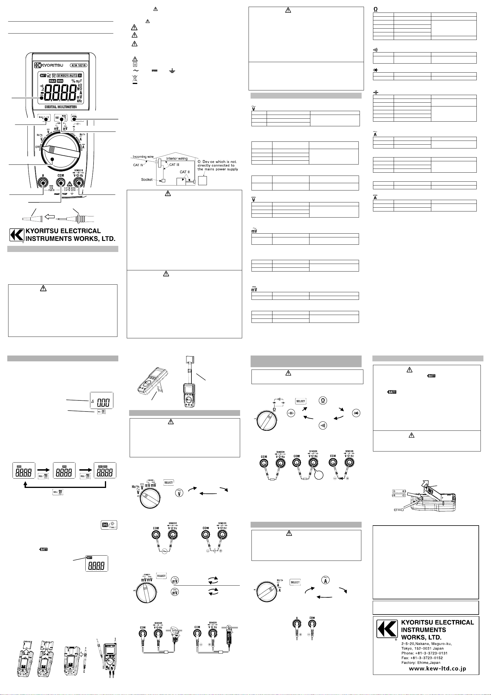
Function Switch
Voltage Terminal
DANGER
measurement.
WARNING
capacitor before
starting a capacitance
measurement
.
WARNING
period of 10 min is required.
Resistance
Diode
AC clamp sensor
DC clamp sensor
Press the SELECT key to toggle functions
BlackRed
♪
Default:Resistance
Continuity
Diode
Capacitance
Max value
Min value
Present value
L
ess than 1 sec
L
ess than 1 sec
L
ess than 1 sec
1.
2.
Wing-type
3.
Replace the batteries with
Flat-type
ACV / ACmV
DCV / DCmV
DIGITAL MULTIMETER
KEW1021R
LCD
HOLD / Back light Key
SELECT Key
REL / MAX・MIN Key
The symbol indicated on the instrument means that the user
must refer to the related parts in the manual for safe operation of the
instrument. It is essential to read the instructions wherever the
symbol appears in the manual.
DANGER is reserved for conditions and actions that
WARNING is reserved for conditions and actions that
CAUTION is reserved for conditions and actions that
● Symbols listed below are used on this instrument.
Measurement Category
O Circuits which are not directly connected to the mains power supply.
CAT II Pri mary el ectrical circuits of equipment connected to an AC
CAT III Primary electrical circuits of the equipment connected directly
CAT IV The circuit from the service drop to the service entrance, and
This instrument is designed for CAT IV 300V/ CAT III 600V. Test
leads M-7066A with the supplied caps are designed for CAT
IV600V/ CAT III 1000V and without the caps are for CAT II 1000V.
are likely to cause serious or fatal injury.
can cause serious or fatal injury.
can cause injury or instrument damage.
User must refer to the manual.
Instrument with double or reinforced insulation.
AC DC Ground (Earth)
This instrument complies to WEEE Directive (2002/96/EC).
Please contact your local distributor at disposal.
electrical outlet by a power cord.
to the distribution panel, and feeders from the distribution
panel to outlets.
to the power meter and primary over current protection
device(distribution panel).
● Use of this instrument is limited to domestic, commercial and light
industry applications. Strong electromagnetic interference or strong
magnetic fields, generated by large currents, may cause malfunction
of the instrument.
● Firmly insert the test leads.
● Do not pull or twist the test leads to prevent the risk of damage.
● Power off the instrument after use. Remove the battery if the
instrument is to be stored and will not be in use for a long period.
● Do not expose the instrument to direct sunlight, high temperature
and humidity or dewfall.
● Use a cloth dipped in water or neutral detergent for cleaning the
instrument. Do not use abrasives or solvents.
● The LCD shows some digits at the Voltage or the Current range even
while the test leads are open. And, it may show some digits instead
of 0 even if the test leads are shorted. However, these phenomena
don’t affect measurement results.
● A resistance measurement takes time to settle the reading if there is
a high resistance or capacitance components.
2. Specification
● Accuracy (Temperature: 23 ± 5°C, Humidity: 45 - 75%)
ACV / RMS (Auto Range)
±1.0 %rdg±3dgt
(40-500Hz)
Guaranteed accuracy : 0.01V-600V, less than 900V peak
Input impedance : approx. 10MΩ
Hz Frequency - ACV measurement (Auto Range)
Range Display Range
(sine wave)
±0.1%rdg±3dgt
Resistance (Auto Range)
6.000kΩ 0.570 - 6.299kΩ
Guaranteed accuracy : 0Ω-40MΩ, Open-loop Voltage : less than 3V
Measurement current : less than 1mA
±0.5 %rdg±2dgt
Continuity
600.0Ω 0.0 - 629.9Ω
Open-loop Voltage : less than 3V, Measurement current : less than 1mA
less than 90Ω
Diode
Guaranteed accuracy : 0V-2V, Open-loop Voltage : less than 3V
Measurement current : approx.0.5mA (Vf=0.6V)
Capacitance (Auto Range)
±2.0 %rdg±5dgt*
±5.0 %rdg±5dgt
* Accuracy after canceling floating capacitance using REL function.
Guaranteed accuracy : 0nF-1000µF
ACA / RMS (Auto Range)
±1.5 %rdg±3dgt
Guaranteed accuracy : 0.01A - 10A, less than 15Apeak
(40-500Hz)
Hz Frequency - ACA measurement (Auto Range)
Current Terminal
COM Terminal
Cap Barrier
1. Safety Warnings
This instrument has been designed, manufactured and tested
according to IEC 61010: Safety requirements for electrical equipment,
and delivered in the best condition after passing quality control tests.
This instruction manual contains warnings and safety rules which have
to be observed by the user to ensure safe operation of the instrument
and to maintain it in safe condition. Therefore, read through these
operating instructions before using the instrument.
● Read through and understand the instructions contained in this
manual before using the instrument.
● Keep the manual at hand to enable quick reference whenever
necessary.
● The instrument is to be used only in its intended applications.
● Understand and follow all the safety instructions contained in the
manual.
● It is essential that the above instructions are adhered to. Failure
to follow the above instructions may impair the protection
provided by the instrument and test leads, and may cause injury,
instrument damage and/or damage to equipment under test.
● Never make measurements under the circumstances exceeding the
designed measurement category and the rated voltage of the
instrument.
● Do not attempt to make measurement in the presence of flammable
gasses. Otherwise, the use of the i nstrument may cause sparking,
which can lead to an explosion.
● Never attempt to use the instrument if its surface or your hand is wet.
● Do not exceed the maximum allowable input of any measuring
range.
● Never open the Battery compartment cover during a measurement.
● To avoid electrical shock by touching the equipment under test or its
surroundings, be sure to wear insulated protective gear.
● Test leads to be used for voltage measurements shall be rated as
appropriate for Measurement Category III or IV according to IEC
61010-031 and shall have a voltage rating of 600V or higher.
● Barriers on the test leads provide protection to keep your fingers and
hands from touching an object under test. Keep your fingers and
hands behind the barriers during measurement.
● Never attempt to make measurement if any abnormal conditions,
such as broken case and exposed metal parts are found on the
instrument or test leads.
● Verify proper operation on a known source before use or take action
as a result of the indication of the instrument.
● Firmly attach the caps to the test leads when performing
measurements in CAT III or higher test environments. When
KEW1021R and the test leads are combined and used together,
whichever is lower category & voltage to earth either of them
belong to is applied.
● Do not rotate the Function Switch if the instrument and the
equipment under test are connected.
● Do not install substitute parts or make any modification to the
instrument. For repair or re-calibration, return the instrument to your
local KYORITSU distributor.
DANGER
WARNING
Guaranteed accuracy : 10Hz-99kHz
% DUTY - ACV measurement
Range Display Range
99.9 % 0.0 – 99.9 %
Guaranteed accuracy : 10%-90%
(Square wave)
(50/60Hz)
DCV (Auto Range)
±0.5 %rdg±3dgt
Guaranteed accuracy : 0V-±600V
Input impedance : approx. 11MΩ(6V range) / 10MΩ(60/600V range)
ACmV / RMS
600.0mV 0.0, 0.9 - 629.9mV
Guaranteed accuracy : 1.2mV-600mV, less than 900mV peak
Input impedance : approx. 900kΩ
(40-500Hz)
AC Clamp Sensor / RMS (Auto Range)
±2.0 %rdg±3dgt
Direct reading from 10mV / A output Clamp sensor
Guaranteed accuracy : 0.12A-200A, less than 300A peak
Input impedance : approx. 900kΩ
+ Sensor accuracy (40-500Hz)
DCmV
Guaranteed accuracy : 0mV-±600mV, Input impedance : approx. 900kΩ
DC Clamp Sensor (Auto Range)
±1.5 %rdg±3dgt
200.0A ±57.0 - ±209.9A
Direct reading from 10mV / A output Clamp sensor
Guaranteed accuracy : 0A-±200A, Input impedance : approx. 900kΩ
+ Sensor accuracy
±0.1 %rdg±3dgt
Guaranteed accuracy : 10Hz-9.9kHz
% DUTY - ACA measurement
Guaranteed accuracy : 10%-90% (Square wave)
DCA (Auto Range)
±1.5 %rdg±3dgt
Guaranteed accuracy : 0A-±10A
●Measuring method : ⊿Σ modulation
●Over-range indication : OL
●Measurement cycle : 2.5 times per second
(1000µF range of Capacitance function 0.05 times per second)
●Crest factor : less than 3 (45-65Hz)
●Applicable standards :
●Withstand voltage : AC5160Vrms 5sec between circuit and enclosure
●IP rating : IP40 (IEC60529)
●Insulation resistance : 100MΩ or more /1000V between enclosure
●Operating temperature and humidity range :
●Storage Temperature and humidity range :
●Power source : DC3V R03/LR03 (AAA) × 2
●Current consumption : 3mA or less
●Battery life : Approx. 200 hours (ACV, continuous, no load, with R03)
●Dimension, Weight : 155(L)×75(W)×40(D)mm,
●Accessories : Test leads (M-7066A), soft case(M-9097)
●Option : Magnet hanger strap (M-9189)
For non-sinusoidal waveforms, add ±0.5 %rdg±5dgt
(Applicable functions : ACV, ACmV, AC clamp sensor, ACA)
IEC 61010-1 /61010-2-033 : CAT IV 300V / CAT III 600V
Pollution degree 2, Indoor use, Altitude up to 2000m
IEC61010-31 (Test leads Model 7066A)
IEC 61326 (EMC) , EN 50581 (RoHS)
and electrical circuit
0 to 40°C, 80%RH or less (no condensation)
-20 to 60°C, 80%RH or less (no condensation)
approx. 250g (including batteries and Wing-type holder)
Instruction manual, 10A/600V Fuse (M-8919, included)
Battery R03 (AAA) 2pcs Flat-type holder, Wing-type holder
Test leads with alligator clips (M-7234)
AC Clamp Sensor (KEW8161), AC/DC Clamp Sensor (KEW8115)
3. Other Functions
● REL Function
Press the REL key to enable this function and store the measured
value to display the differences between the stored value and the
values measured in further tests. The measurement range will be
fixed when the REL function is enabled, and the measuring range will
be between the initial value and the full scale value.
Press the REL Key again to release the stored value.
“Δ” appears and “AUTO” disappears
when REL Key is pressed.
One press: REL ON
Another press: REL OFF
*To activate REL function, MAX/MIN function should be disabled.
● Max / Min value display function
This function is to display the measured max and min values on the
LCD during a measurement. Press the MAX/MIN key 1 sec or longer
to start recoding of max and min values. Then the LCD shows the
latest max val ue. After that, the min and present values can be
toggled and checked by pressing the MAX/MIN key (less than 1
sec).
To disable this function, press the MAX/MIN key 1 sec or longer.
* To activate MAX/MIN function, REL function should be disabled.
● Data hold function
Press the HOLD key (less than 1 sec). The LCD shows “H” mark and
the reading will be held (Data hold mode). The max/ min values are
not updated in MAX/MIN mode. Press the HOLD key
again (less than 1 sec) to release the display.
● Backlight function
Press the Backlight key 1 sec or longer to turn
on the backlight. Press the Backlight key another 1 sec or longer to
turn it off. The light automatically turns off in 1 min.
● Low battery indication
The LCD shows “ ” mark when the batteries fall below the
normal operating voltage.
new ones when this mark
appears.
● Sleep Function
Automatically powers off the instrument in about 15 min after the last
switch operation.
To exit from the Sleep mode, rotate the Function switch or press any
key. To disable the Sleep function, press the HOLD/Backlight key
and power on the instrument.
Confirm that the LCD shows “P.OFF” about 1 sec.
●How to store test leads
Attach the Wing-type holder to the back of the instrument to store the
test leads.
1. Attach the Wing-type holder to the back of the instrument.
2. Fit the barrier on the test lead into the groove between the
instrument and the Wing-type holder.
● Other convenient functions
Magnet hanger strap
(option)
Tilt stand
4. ACV / DCV / ACmV / DCmV Measurement
● Before starting a measurement, always check and confirm
the Function switch is in the appropriate measurement
position and the test leads are connected to the proper input
terminals.
● Never make measurement on a circuit in which voltage over
600V exists.
● Keep your fingers and hands behind the barrier during
4.1 ACV / DCV/ ACmV / DCmV measurement
(1) Set the Function switch to ACV, DCV, ACmV or DCmV position.
For frequency or DUTY measurement, set the switch to ACV
and press the SELECT key.
Default : ACV
Press the SELECT key to toggle functions
(2) Connect the test leads to the Voltage and COM terminals.
Black
4.2 Clamp sensor (option) measurement
(1) Set the Function switch to ACmV or DCmV position and press the
SELECT key. LCD shows “SENSOR”.
Default :ACmV
Default :DCmV
Press the SELECT key to toggle functions
(2) Connect the clamp sensor to the Voltage and COM terminals.
FrequencyDUTY
Red
Sensor mode
(ACA)
Sensor mode
(DCA)
5. Resistance / Diode / Continuity / Capacitance
Measurement
Never use the instrument on an energized circuit. Discharge the
(1) Set the Function switch to the resistance position. For continuity
check or diode/ capacitance measurement, press the SELECT key.
(2) Connect the test leads to the Voltage and COM terminals.
or Capacitance
NOTE
● LCD shows ”OL” when the test leads are open.
(except for capacitance measurement)
● The LCD shows “OL” if the test lead connection is reversed for diode
measurement.
● Measurement time on 600μF/1000μF range is a bit long.
(20sec max.)
Continuity
6. ACA / DCA Measurement
● T he value for the maximum input current on ACA and DCA
ranges is 10A (protected by fuse). Do not apply current that
exceeds 10A.
● If measuring a current of 6A or higher, the duration of
measurement should be within 2 min. After that, a rest
(1) Set the Function switch to ACA or DCA position. For frequency/
DUTY measurement, press the SELECT key while the Function
switch is in ACA position.
Default : ACA
DUTY
Press the SELECT key to toggle functions
(2) Connect the test leads to the Current and COM terminals.
Frequency
7. Battery / Fuse Replacement
WARNING
● Replace the battery when the " " mark- low battery voltage
warning- appears on the LCD.
Otherwise, precise measurement cannot be made. If the battery
is completely exhausted, the LCD goes blank without showing
the " " mark.
● Disconnect the test leads from the object under test and power
off the instrument before opening the Battery compartment
cover for battery or fuse replacement.
● The fuse gets hot after current measurement and may cause
burn i njury. If replacing the batteries or fuse after current
measurement, a rest period of 10 min before you do.
● Use the designated fuse only.
● Do not try to replace the battery or fuse if the surface of the
instrument is wet.
CAUTION
● Do not mix old and new batteries.
● Install a batteries in correct polarity as indicated in the
Battery Compartment.
(1) Set the Function Switch to "OFF" position.
(2) Untighten the screw on the back of the instrument.
(3) Remove the Battery compartment cover and replace the
batteries or fuse.
(4) Attach the cover to the instrument and then secure the cover
by tightening the screw.
Screw
Battery
Fuse
(10A/600V, size : 6.3 × 32mm, Fast Acting type)
Kyoritsu reserves the rights to change specifications or designs
described in this manual without notice and without obligations.
holder
3. Then it will be easier to see the displayed readings during a
measurement.
holder
Black
NOTE
● If the connection is reversed, the “ - “ mark will be displayed on the
LCD. (DCV measurement).
● Press the REL key to adjust the reading on the DC clamp sensor to
“0”.
● The sensor mode corresponds to direct reading with 10mV/A
output clamp sensor.
Red
BlackRed
NOTE
● If the connection is reversed, the “ - “ mark will be displayed on the
LCD. (DCA measurement).
● If the fuse is blown, please refer to 7. Fuse Replacement and replace
it with a new one.
9-15 92-2238B
 Loading...