

Page 1
1. SAFETY WARNINGS
Th is in st ru me nt has been de si gn ed an d tes te d acc or di ng
to IEC61010: Safet y requi remen ts for Elec tro nic Measu ring
App aratus, and de livered in the best condi tion after pas sing
quality control tests. This instruction manual contains warnings
and safet y rules whi ch have to be obs erved by the us er to
ensure safe operation of the instrument and to maintain it in safe
condition. Therefore, read through these operating instructions
before using the instrument.
WARNING
● Read through and understand instructions contained in this
manual before using the instrument.
● Ke ep the man ua l at ha nd t o ena b le qu i ck re f er en ce
whenever necessary.
● The instrument is to be used only in its intended applications.
● Understand and follow all the safety instructions contained in
the manual.
It is essential that the above instructions are adhered to. Failure
to follow the above instructions may cause injury, instrument
damage and/or damage to equipment under test.
The symbol
indicated on the instrument, means that the user
must refer to the related parts in the manual for safe operation of
the instrument. It is essential to read the instructions wherever the
symbol appears in the manual.
DANGER is reserve d for conditions and acti ons that are
likely to cause serious or fatal injury.
WARNING is reserved for conditions and actions that can
cause serious or fatal injury.
CAUTION is reserved for conditions and actions that can
cause injury or instrument damage.
Instruction Manual
Voltage Sensor Series
KEW 8325F
Flicker Sensor
DANGER
● Never make measurement on a circuit in which the electrical
potential exceeds AC600V.
● Do not make measurements when a thunder is rumbling.
St op measu re me nts imme di at ely an d dis co nn ect th e
instrument from the devices under test.
● Do not attempt to make measurements in the presence of
flammable gasses.
Otherwise, the use of the instrument may cause sparking,
which can lead to an explosion.
● Be especially careful about the possible shorting where the
measured conductor is not insulated.
● Never attempt to use the instrument if its surface or your
hand is wet.
● Remove the Measuring terminals from the circuit under test
before connecting / inserting the Output connector.
● Do n ot exc ee d th e ma xi mum all ow abl e in pu t of an y
measuring range.
● Confirm a proper operation of this sensor on a well-known
power source before taking countermeasures against the
measured results.
WARNING
● Never attempt to make any measurement if any abnormal
conditions, such as a broken cover or exposed metal parts
are present on the instrument.
● Do not install substitute parts or make any modification to the
instrument. Return the instrument to your local KYORITSU
distributor for repair or re-calibration in case of suspected
faulty operation.
● Keep your fingers and hands behind the safety barrier during
measurements.
CAUTION
● Do not step on or pinch the cord, or it may damage the jacket
of cord.
● Grasp the connector to remove the output terminal from the
instrument.
● Put the instrumen t on a st abl e place where is f ree from
vibrations or shocks.
● Firmly fix the Sensor unit and Measuring terminal so that
they don't fall off due to the weight of sensor or test leads.
●
Keep away Floppy Disks, Magnetic Cards, PCs and Displays
from the magnet, which is attached to the backside of the sensor.
● Do no t expose th e ins tr um en t to direct su nl ig ht , hig h
temperatures, humidity or dew.
● Not to give shocks, such as vibration or drop, which may
damage the instrument.
● Use a damp cloth with neutral deterg ent for cleaning the
instrument. Do not use abrasives or solvents.
Safety symbols
Must refer to the instructions in the manual for safety
Indicates a Instrument with double or reinforced insulation
Indicates AC
◊ Measurement categories(Over-voltage categories)
To ensure safe operation of measuring instruments, IEC 61010
establishes safety standards for various electrical environments,
ca tegor iz ed as CAT.I to CAT.IV, and ca lled measurem en t
categories. Higher-numbered categories correspond to electrical
environments with greater momentary energy, so a measuring
instr um ent desig ne d fo r CAT.I II enviro nm ents can endu re
greater momentary energy than one designed for CAT.II.
CAT.I : Se co nd ar y electrical ci rc ui ts connected to an A C
electrical outlet through a transformer or similar device.
CAT.II : Primary electrical circuits of equipment connected to an
AC electrical outlet by a power cord.
CAT.III : Primary electrical circuits of the equipment connected
directly to the distribution panel, and feeders from the
distribution panel to outlets.
CAT.IV : Th e ci rc uit fr om the s er vic e drop to t he ser vi ce
ent r an c e, an d to t he po wer m et er an d p ri m ary
overcurrent protection device (distribution panel).
2. FEATURES
• This is a Voltage Sensor designed for KEW6310 to measure AC
voltage up to 600V.
• Use with Power Quality Analyzer (KEW6310) enables flicker
measu remen t accor ding to IEC61000-4-15 (Fl ick ermet er –
Functional and design specifications).
• Designed to following international safety standards:
IEC61010-1 Measurement Category (CAT.) III 600V
IEC61010-031 Requirements for hand-held probes
• Int ern al di fferential amplifi er is equi ppe d, en abl ing floa ting
voltage measurement.
3. SPECIFICATIONS
• Max. input voltage AC600Vrms, 848.4V Peak
• Input system Diff eren tial input (can measur e floa ting
voltages)
• Output voltage
AC600mV/ AC600V (Output/Input: 1mV/ V)
• Measuring ranges and accuracy
Measuring Range Frequency range Accuracy
6 ~ 600V
50/ 60Hz ±0.5%rdg±0.1mV
40Hz ~ 1kHz ±1.5%rdg±0.2mV
• Temperature and Humidity Ranges(guaranteed accuracy):
23ºC±5ºC, relative humidity 85%or less (without condensation)
• Operating Temperature and Humidity Ranges:
0~40ºC, relative humidity 85%or less (without condensation)
• Storage Temperature and Humidity Ranges
-20~60ºC, relative humidity 85%or less (without condensation)
• Power supply (supplied via output terminal)
DC : ±(5V±10%)
• Current consumption 1mA (Typ.)
• Input impedance Approx.3.2MΩ
• Output impedance Approx.1kΩ
• Location for use Altitude up to 2000m, Indoors
• Safety Standard
IEC/EN61010-1:2001 Measurement Category (CAT.) III 600V
Pollution Degree 2
IEC/EN61010-031:2002
EN61326:2001 (EMC Standard)
• Withstand Voltage AC5350Vrms (50/60Hz)for 5sec.
( betw ee n Me a s u r ing term in a l an d
enclosure)
•
Insulation Resistance
50MΩor greater at 1000V
( betw ee n Me a s u r ing term in a l an d
enclosure)
• Dimension & weight 8 7(L ) x 26(W ) x 17( D) mm (ex cl ud ing
protrusions)
Approx. 135g
• V,COM Cable length Approx. 0.9m
• Output Cable length Approx. 1m
• Output Connector MINI DIN 6PIN
• Accessories Instruction manual
• Option 7197(small Alligator clip)
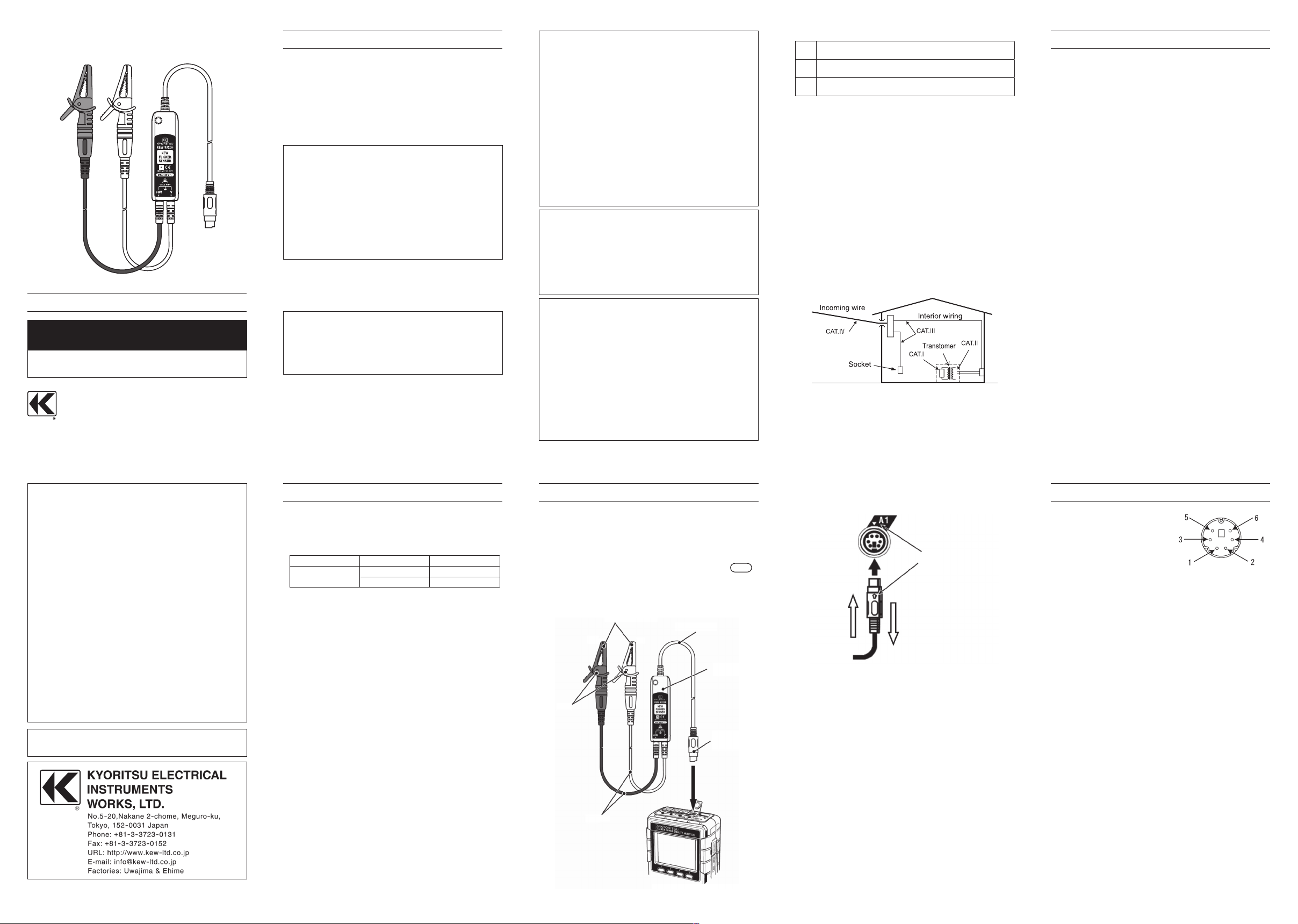
4. HOW TO USE/ SENSOR LAYOUT
Connect the Output connector to the Input terminal (A1) of the
Power Quality Analyzer (KEW6310).
This sensor operates only at A1 terminal. Do not use 2pcs or
more of KEW8325F at the same time.
Clip the V and COM measuring terminals onto the conductor
under test.
Start KEW6310 and select Flicker measurement at
QUALITY
menu.
Detailed operating instru ctions are given in t he Ins truction
manual for KEW6310.
5. DIN Plug pin assignment
1: +DC power supply Pin (+5V)
2: -DC power supply Pin (-5V)
3: GND Pin
4: No use
5: Output signal Pin
6: Sensor recognition pin
(Resistance between Pin 3 and Pin 6: 20kΩ)
* Above figure shows the pin assignment seeing the Clamp sensor
from output connector part. The figure of the pin assignment of
connection terminal is symmetrical to above figure.
07-08 92-1935
DISTRIBUTOR
Kyoritsu reserves the rights to change specifications or designs
described in this manual without notice and without obligations.
KYORITSU ELECTRICAL INSTRUMENTS WORKS, LTD.,
TOKYO, JAPAN
Measuring terminal
(COM)
(V)
Barrier
Test lead
Power Quality Analyzer (KEW6310)
Output cable
Sensor
Output connector
Output signal
Power supply
Match the arrow marks
 Loading...