

Page 1
Instruction Manual
sensor
FLEXIBLE CLAMP SENSOR
POWER CLAMP SENSOR Series
KEW 8130
Cauti ons for u sing this clamp sensor with KEW5010/5020:
Some KEW5010/5020 that were manufactured before the specific
timing of p roduction may not be used with this clamp sens or. Please
refer to 6-3 C onnec ting w ith Logger (K EW5010/5020) a nd
check the serial no..
1. SAFETY WARNINGS
This clamp sensor has been designed and tested according to
IEC61010-1: Safety Requirements for Electronic Mea suring A pparatus,
and delivered in the best condition after passing quality c ontrol tests.
This instruction manual contains warnings and safety rules which have
to be observed by the user to ensure safe operation of the clamp
sensor and to maintain it in safe condition. Therefore, read throu gh
these operating instructions before using the clamp sensor.
# DANGER
● Read through and understand instructions contained in this
manual before starting to use the clamp sensor.
● Keep the manual at hand to enable quick reference whenever
necessary.
● The clamp sensor is to be used only in its intended applications.
● Understand and follow all the safety instructions contained in
the manual.
It is esse ntial that the above instruc tions are adhered to. Failure to
follow the above instructions may cause injury, clamp sensor
damage and/or damage to equipment und er test. K YORITS U is not
liable for any damage resulting from the users mishandling of the
clamp sensor.
The symbo l # indicated on the c lamp sensor means that the user
must refer to the related par ts in the manual for safe operation of the
clamp sensor. It is essential to read the instructions wherever the #
symbol appears in the manual.
# DANGER: is reserved fo r conditions and actions that are likely
to cause serious or fatal injury.
# WARNING: is reserved for conditions and actions that can
cause se rious or fatal injury.
# CAUTION: is reser ved for conditions and actions that can
cause injury or instrument damage.
# DANGER
● With attention to the measurement c ategory to whi ch the object
under test belong s, and do not make measurements on a circuit
in which t he electrical potential exceeds the following values:
300V fo r CAT. IV and 600V for CAT. III or lower categories.
● Never attempt to make any measurement if any abnormal
conditions, such as a broken cover or exposed metal par ts are
present on the clamp sensor.
● Do not disass emble, install substitute parts o r make any
modif ication to the clamp sensor. Return the c lamp sensor to
your local KYORITSU distributor for repai r or re- calibration in
case of suspected faulty operation.
● Do not use the clamp sensor if the clamp senso r or your hands
are wet. Otherwise, electrical shock acci dent may oc cur.
● Use insulated protective gears for your safety w hen using this
clamp sensor.
Do not step o n or pinch the cord; it may damag e the jacket of cord.
●
●
Do not expo se the clamp sensor to direc t sunlight, high temperatures,
humidit y or dew. Otherwise, it may cause deformation or insulation
degradation and cannot meet the original specification.
● Not to give shocks, such as vibration o r drop, whi ch may
damage the clamp sensor, during transit or use.
● Use a damp cloth with water or neutral deter gent for c leaning the
clamp sensor. Do not use abrasives or solvents.
● This clamp sensor is not designed to be dust or waterproof. Do
not use it dusty places or where the clamp sensor is likely to be
wet. It may cause troubles on the clamp sensor.
● Never pinch foreign mat ters or give vibrations at the jointed
parts of this clamp senso r. Otherwise, matching are a of Jaws
may be damaged and cause influences on the measurements.
● Do n ot bend or pull the ro ot of the cable in order to preve nt
breaks in t he cable.
● Never apply the current exceeding the measuring r ange for a
long time. It may damage the clamp sensor.
● Never co nnect /remove the connector s while connected devices
are on or clamping o nto the co nducto r under test. Otherwise, the
connected devices or clamp sensors may be damaged.
● Ac curate measurement may not b e obtain ed in the vicinit y of
strong magnetic f ields such as transformers, hi gh-current
circuits or wireless machines.
Meaning of symbols on the clamp sensor:
User must refer to the explanations in the instruction manual
#
for safety reasons.
Clamp sensor with double or reinforced insulation
Do not apply around or remove from un- insulated hazardous
live conductors, which m ay render e lectr ic shock, electric
burn, or arc flash.
AC
Crosse d-out wheel bin symbol (accordi ng to WEEE Directive:
2002 / 96/ EC) indicating that this electrical p roduct may not
be treate d as household waste, but that it must be co llecte d
and treated separately.
# WARNING
# CAUTION
Measurement Category:
To ensure safe operation of measuring instruments, IEC 61010
establishes safety standards for various electrical environments,
catego rized as O to CAT.IV, and called measurement c ategories.
Higher-numbered categories correspond to electrical environments
with greater momentary energy, so a measuring instrument designed
for CAT.III environments can endure greater momentary energy than
one designed for CAT.II.
O : Circ uits whi ch are not directly connected to the mains
power supply.
CAT.II : Electric al circ uits of equipment c onnec ted to an AC
electrical outlet by a power cord.
CAT.III : Pr imary electrical c ircuits of the equipment c onnec ted
direct ly to the distribu tion panel, and feeders from the
distribution panel to outlets.
CAT.IV : The circuit f rom the service drop to the service ent rance,
and to the power meter a nd primary over- current
protection device (distribution panel).
2. FE AT UR E S
● T his is a Cla mp Senso r capable of measu ring AC current up to
1000A.
● Flexibl e and light weight because of an air core c oil used at the
Clamp Sensor part
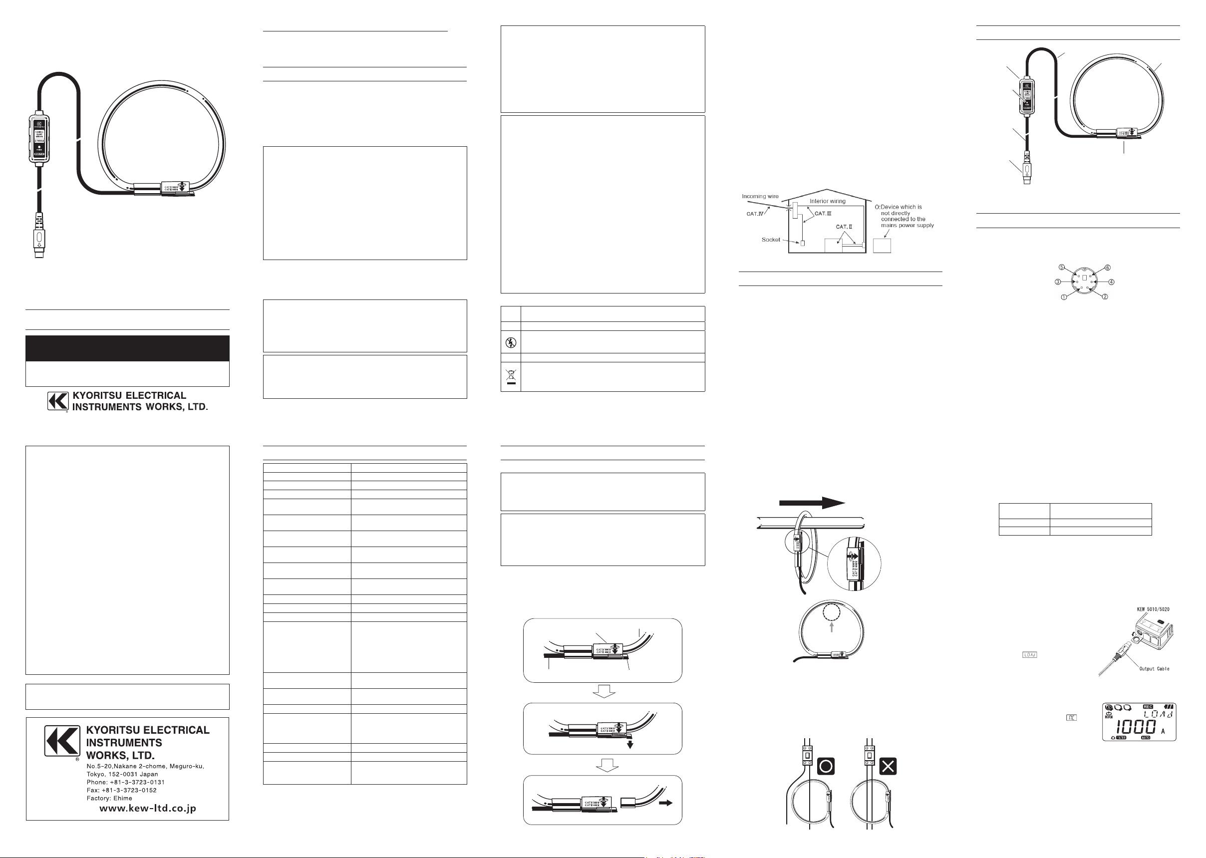
3. CLAMP SENSOR LAYOUT
Cable
Circuit box
Power indicator
Output cable
Output terminal
Joint part of the sensor
Clamp
4. PIN ASSIGNMENT FOR OUTPUT TERMINAL
The pin assignment for the output ter minal of this clam p sensor i s as
follows.
Output(Hi)
COM(Output Lo)
3.0 to 5.5V -3.0 to -5.5V
* Pin assignment at the connecting terminal of measuring instrument
is symmetrical to above figure.
● Output signal passes bet ween 3 and 5 of Output terminal.
● This clamp senso r is supplied power v ia an Output cable. Power
supply of +3.0 to +5.5V is requir ed between 1 and 3 of Output
terminal and -3.0 to -5. 5V is required bet ween 2 and 3 of Output
terminal.
N.C.
N.C.
DISTRIBUTOR
Kyoritsu reserves the rights to change specifications or designs
described in this manual without notice and without obligations.
5. SPECIFICATION
Model name KEW8130
Rated current AC1000A
Output voltage AC500mV/AC1000A(0.5mV/A)
Measuring range AC0 - 1000Arms(1850Apeak)
Accuracy
(sine wave input)
Phase characteristics 45 to 65Hz: within ± 2°
Current consumption
(at power supp ly ±5V)
Temperature & humidit y
range (guaranteed accuracy)
Operating temperature &
humidity range
Storage temperature &
humidity range
Max allowable input AC1300A (continuous)
Output impedance 100Ω or less
Environmental condition Altitude up to 2000m, in-do or use
Applicable standards IEC 61010 -1
Withstand voltage AC5160V (r.m.s. 50/6 0Hz) / 5 sec.
Insulation resistance 50MΩ or more/ 1000V
Measureable conductor size Max ø 110mm
Cable length Between clamp sensor – circuit box:
Output terminal MINI DIN 6PIN
Weight Approx. 180g
Accessories Instruction manual
±0.8%rdg±0. 2mV(45 - 65Hz)
±1.5%rdg±0.4mV(40 - 1kHz)
40 to 1kHz: wit hin ±3°
max. 2mA
23±5º C, Relati ve humidity: 85% or
less (no condensation)
-10 to 50ºC, Relative humidity: 85% or
less (no condensation)
-20 to 60 ºC, Relative humi dity: 8 5% or
less (no condensation)
IEC 61010 -2- 030
IEC 61010 -2- 032
Measurement CAT III(600Vrms), CAT
IV ( 30 0Vrms)
Pollution degree 2
IEC 6132 6-1
Between circuit – clamp sensor
Between circuit – clamp sensor
approx. 2.7m
Between circuit box – output terminal:
approx. 0.2m
Cable marker: No.1 to 3 (2pcs each)
Carrying case (MODEL9 095)
6. OPERATING INSTRUCTIONS
● With attention to the m easurement cate gory to which the objec t
under test belongs, and do not make measurements on a circuit
in which t he electrical potential exceeds the foll owing values:
300V fo r CAT. IV and 600V for CAT. III or lower categories.
● The m easurable conductor size is max. 110mm in diameter.
Accurate results cannot be obtai ned if the clamp sensor is not
closed firmly.
● When disconnecting the output terminal from the measuring
instrument, do so by removin g the plug f irst and not by pulling
the cord.
6-1 Mea suring meth od
(1) Connect the output terminal to the input terminal on the
measuring instrument.
(2) Power on the measuring instrument.
(3) Press the Joint accordin g to the following illustrations and
unlock it.
Cable
# DANGER
# CAUTION
Joint
Sensor
Lock
1. Press
2. Unlock
Clamp onto one conductor under the te st. Locate the conductor
(4)
to the position as shown in the below figure. When connecting
the Clamp sensor w ith our Power meter (M ODEL6 315 etc.),
check the direction of the Guide ar row mark indicating the
current flowing direc tion marked on the Joint of the Clamp
sensor to make the phase of the current under test and output
voltage synchronized.
Source
Reference position
of the conductor
Reference test position of the conductor
for KEW8130 clamp sensor
(5) Confi rm that the Joint on the Clamp sensor is firmly locked.
● Jointed part of the Clamp sensor may be disconnected if
excessive force is applied to.
● Clamp onto one c onduc tor only; measure ments cannot be ma de
when clamping single-phase (2-wire) or three-phase (3-wire) at
the same t ime.
Load
Guide arrow mark
Connecting with Power meter (KEW6315/KEW6310/KEW6305/
6-2
MODEL6300)
Whe n this clamp sensor is detected by the auto-d etecti on function
of our KEW6310/ 6315 Power meter after the connection, the type
of the clamp sensor will be displayed as follows. O n KEW6 310, the
displayed model name will not be KEW8130, however, this is
not a malfunctio n. Enter the model name according to the follow ing
table if setting the typ e of the clamp senso r directly.
Power meter Model name displayed through
KEW 6310 MODEL 8124
KEW 6315 MOD EL8124 /8130
● MODEL6300 / KEW6 305 does not detect the connected clamp
sensor s automat ically. Enter the model name dir ectly:
MODEL8124 (1000A).
● For the detailed setting of the clamp sens or, please refer to the
instru ction manual for each Power m eter.
6-3 Connec ting with Logger (K EW5010/5020)
When using this c lamp sensor together with our KEW5010 / 5020
Logger;
(1) Connect the clamp sensor to
CH1 of KEW5 010/ 5020 while
KEW5010 / 5020 is in powered
off status.
(2) Then power on KEW5010 /
5020. Time will be displayed,
and then
will be displayed. (K EW5010/
5020 checks the connected
clamp sensors when it is
powered o n, and detects and
displays t he clamp sensor t ype and a proper range
automatically.)
(3) Now the instrument is ready for
measurements. When
connection) is displayed on the
LCD; it means no clamp sensor is
connected to the selected channel
or the connection is loo se.
In this case, check the connecti on and rec onnec t the clamp
sensor,and power of f KEW5010 / 5020. Then power it on again.
* Only KEW5010 / 5020 which have the following or later ser ial
number may be used with this cl amp sensor.
KEW5010: No.803156 0 or later
KEW5020: No.8 029792 or later
the auto-detection function
and 1000A
(no
03-14 92-2177
 Loading...