

Page 1
1. SAFETY WARNINGS
This instrument has been designed and tested according to IEC61010:
Safety Requirements for Electronic Measuring Apparatus, and delivered in
the best condition after passing quality control tests. This instruction manual
contains warnings and safety rules which have to be observed by the user to
ensure safe operation of the instrument and to maintain it in safe condition.
The ref ore, read through these oper ating in struction s before using the
instrument.
WARNING
● Read through and understand instructions contained in this manual
before using the instrument.
● Keep the manual at hand to enable quick reference whenever necessary.
●The instrument is to be used only in its intended applications.
● Understand and follow all the safety instructions contained in the manual.
It is essential that the above instructions are adhered to. Failure to follow
the above instru ctions may caus e injury, in strument damag e and/or
damage to equipment under test.
The symbol
indicated on the instrument, means that the user must refer
to the related parts in the manual for safe operation of the instrument. It is
essential to read the instructions wherever the
symbol appears in the
manual.
DANGER is reserved for conditions and actions that are likely to
cause serious or fatal injury.
WARNING is reserved for conditions and actions that can cause
serious or fatal injury.
CAUTION is reserved for conditions and actions that can cause
injury or instrument damage.
DANGER
● Never make measurement on a circuit in which the electrical potential
exceeds AC600V.
● Connect this instrument to the secondary side of a circuit breaker
because the secondary side is protected by a breaker at accidental
short-circuit. Do not make measurements at the primary side because
Current capacitance at the primary side is quite big and serious damage
may occur at accidental short-circuit.
WARNING
● Never attempt to make any measurement if any abnormal conditions,
such as a broken cover or exposed metal parts are present on the
instrument.
● Do not disassemble, install substitute parts or make any modification to
the instrument. Return the instrument to your local KYORITSU distributor
for repair or re-calibration in case of suspected faulty operation.
● Do not use the instrument if the instrument or your hands are wet.
Otherwise, electrical shock accident may occur.
● Us e ins ula t ed prot e cti ve gea rs for you r safe ty whe n usi ng thi s
instrument.
CAUTION
●Do not step on or pinch the cord; it may damage the jacket of cord.
● Do not expose the instrument to direct sunlight, high temperatures,
humidity or dew. Otherwise, it may cause deformation or insulation
degradation and cannot meet the original specification.
● Not to give shocks, such as vibration or drop, which may damage the
instrument, during transit or use.
● Use a damp cloth with neutral detergent for cleaning the instrument. Do
not use abrasives or solvents.
● This instrument isn't waterproofed. Do not use i t dusty places or
where the instrument is likely to be wet. It may cause troubles on the
instrument.
● Never pinch foreign matters or give vibrations at the jointed parts of this
instrument. Otherwise, matching area of Jaws may be damaged and
cause influences on the measurements.
● Do not bend or pull the root of the cable in order to prevent breaks in the
cable.
● Never apply the current exceeding measuring range for a long time. It
may damage this instrument.
● Never connect/remove the connectors while connected devices are
on or clamping onto the conductor under test. Otherwise, connected
devices or sensors may be damaged.
● Accurate measurement may not be obtained in the vicinity of strong
magnetic field such as transformers, high-current circuits or wireless
machines.
Safety symbols
Refer to the instructions in the manual.
Indicates a Instrument with double or reinforced insulation
○
Must wear a insulated gears such as a pair of rubber gloves when
connecting / disconnecting the sensor to / from live conductors.
AC
◊ Measurement categories(Over-voltage categories)
To ensure safe operation of measuring instruments, IEC 61010 establishes
safety standards for various electrical environments, categorized as CAT.I
to CAT.IV, and called measurement categories. Higher-numbered categories
correspond to electrical environments with greater momentary energy, so a
measuring instrument designed for CAT.III environments can endure greater
momentary energy than one designed for CAT.II.
CAT.I: Secondary electrical circuits connected to an AC electrical outlet
through a transformer or similar device.
CAT.II: Pri mary electrica l c ircui ts of eq uipment conn ected to an AC
electrical outlet by a power cord.
CAT.III: Primary electrical circuits of the equipment connected directly to
the distribution panel, and feeders from the distribution panel to
outlets.
CAT.IV: The circu it f ro m the ser vice drop to the servi ce e ntr anc e,
and to the power m et er and primary overcu rrent protection
device(distribution panel).
2. FEATURES
●This is a Clamp Sensor capable of measuring AC current up to 3000A.
● Flexible and light weight because of an air core coil used at the Sensor
part
●One BOX contains measuring circuit for 3-channel. (8129-03)
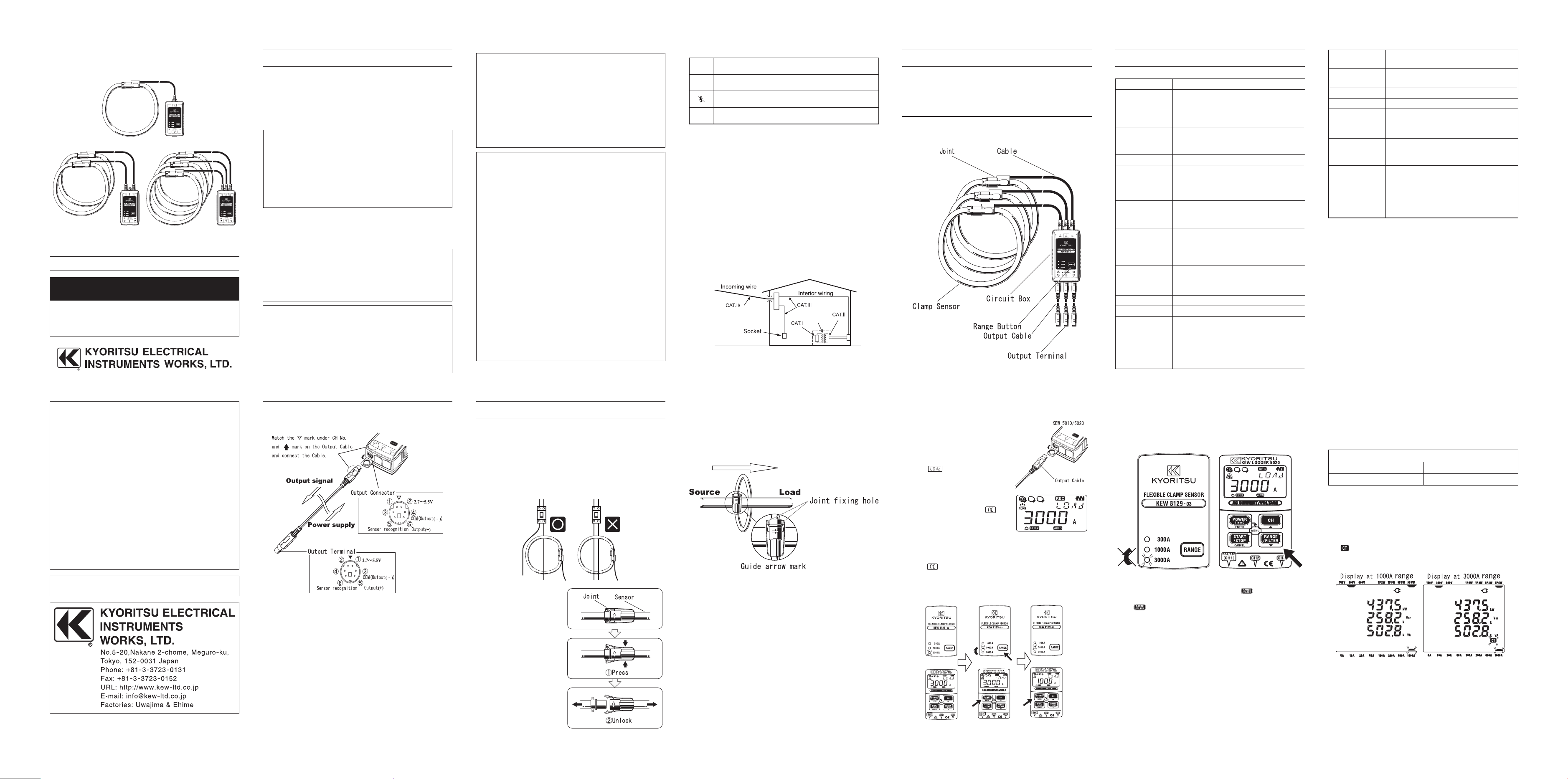
3. INSTRUMENT LAYOUT
5. PIN ASSIGNMENT FOR OUTPUT TERMINAL
& OUTPUT CONNECTOR
* Pin assignment at the connectin g term inal of measuring instrumen t
(MODEL6300, KEW5010 / 5020) is symmetrical to above figure.
* Output signal passes between 3 and 5 of Output terminal and between 4
and 6 of Output connector.
* This instrument is supplied power via an Output cable. Power supply of
2.7 ~ 5.5V (200mVA) is required between 1 and 3 of Output terminal and
between 2 and 4 of Output connector.
* Resistance between 3 and 6 of Output terminal and between 4 and 5 of
Output connector is as follows.
300A Range: 910kΩ, 1000A Range: 360kΩ, 3000A Range: 510kΩ
( Resistance cannot be measured while the instrument is powered off
status.)
4. SPECIFICATION
KEW8129-01 is for 1 CH, KEW8129-02 is for 2 CH and KEW8129-03 is for 3 CH
Model Name 8129-01, -02, -03
Rated current 300A/ 1000A/ 3000A
Output voltage 300A Range: AC500mV/AC300A(1.67mV/A)
1000A Range: AC500mV/AC1000A(0.5mV/A)
3000A Range: AC500mV/AC3000A(0.167mV/A)
Measuring range 300A Range: 30 ~ 300Arms(424Apeak)
1000A Range: 100 ~ 1000Arms(1414Apeak)
3000A Range: 300 ~ 3000Arms(4243Apeak)
Accuracy (sine wave input)
±1.0%rdg (45 ~ 65Hz)
Phase characteristics within ±1°
300A Range: 30 ~ 300A(45 ~ 65Hz)
1000A Range: 100~1000A(45 ~ 65Hz)
3000A Range: 300 ~ 3000A(45 ~ 65Hz)
Current consumption
(at power supply 3V)
8129-01: 13mAtyp.
8129-02: 14mAtyp.
8129-03: 15mAtyp.
Te m p er at u re & Hu m i di t y
ranges (guaranteed accuracy)
23ºC±5ºC,relative humidity 85%or less
(no condensation)
Operating Temperature
& Humidity ranges
0 ~ 50ºC, relative humidity 85%or less
(no condensation)
Storage Temperature
& Humidity ranges
-20 ~ 60ºC, relative humidity 85%or less
(no condensation)
Max allowable input AC3600A continuous (45 ~ 65 Hz)
Output impedance 100Ω or less
Environmental condition
Altitude up to 2000m, in-door use
Applicable standards IEC 61010-1, IEC 61010-2-032
Measurement CAT.III 600V Pollution degree 2
EMC:EN 61326
・EN 55022
・EN 61000-4-2 (perfomance criterion B)
・EN 61000-4-3 (perfomance criterion B)
Withstand voltage AC5350V (RMS value 50/60Hz) / for 5 sec
between circuit and sensor
Insulation resistance 50MΩ or more/ 1000V
between circuit and sensor
Measurable conductor size
max diameter 150mm
Dimension 111(L) × 61(W) × 43 (D)mm (except for protrusions)
Cable length Sensor part: approx 2m
Output cable: approx 1m
Output terminal MINI DIN 6PIN
Weight 8129-01: approx 410g
8129-02: approx 680g
8129-03: approx 950g
Accessory Instruction manual
Output cable (M-7199)
・
8129-01: 1pce
・
8129-02: 2pcs
・
8129-03: 3pcs
Carrying Case (M-9137)
6. OPERATING INSTRUCTIONS
Note
● Jointed part of the Clamp sensor may be disconnected if excessive force
is applied to. Insert pins in the Joint-fixing-hole to ensure a firm connection.
(see the illustration below)
Use non-conductive pin for fixing the Joint in order to avoid getting an
electrical shock.
● Clamp onto one conductor only; measurements cannot be made when
clamping single-phase (2-wire) or three-phase (3-wire) at the same time.
6-1 Measuring method
(1)
Connect the Output terminal
t o t he I np u t t er m i n a l
o n th e me as u ri n g un it
(K EW5010/5020 Log ger,
6300 Power meter etc.・・・)
(2) Power on t he measuring
unit.
(3) Press the Joint according
to the following illustrations
and unlock it.
6-2 Connecting with KEW5010 / 5020 Logger
When using this sensor together with our KEW5010 / 5020 Logger;
(1)
Connect the sensor to CH1 of KEW5010
/ 5020 (if CH1 is used, connect to CH2)
while KEW5010 / 5020 is in powered off
status.
(2)
Th e n po w e r on KE W5010 / 5 020.
Ti me is d isp lay ed, a nd a me ssa ge
of
and select ed range are
displayed. Sensor type and a proper
range are automatically recognizedand
selected when powering on the Logger.
(3) No w the instru m e n t is rea d y f o r
me a s u r e m e nts. Wh e n
(n o
connection) is displayed on the LCD;
it means no Sensor is connected to
the selected channel or connection
is loose. In this case, check the connection and reconnect the sensor,
and power off KEW5010 / 5020. Then power it on again.
* Some KEW5010 / 5020 may not be used with thes e s ensors.
is displayed on the LCD of KEW5010 / 5020 after powering
it on with sensors connected.
* To change ranges, press the RANGE Button on the sensor and select a
proper range, and then power off KEW5010 / 5020, and power on again.
Following illustrates how to change 3000A range to 1000A range.
① Press the RANGE Button on the sensor to select any desirable range.
② LED for 1000A range will light up.
③ Power off KEW5010 / 5020.
④ Power it on again, and confirm the lighting LED on the sensor and the
indication on the LCD of KEW5010 / 5020 are corresponding each
other.
* Range of the sensor cannot be changed via the
Button on KEW5010
/ 5020.
* The
Button on KEW5010 / 5020 switches Filter function on / off.
6-3 Setting on MODEL6300 Power Meter
When using this instrument together with our Power meter, MODEL6300,
setting for the type of Clamp and available Current ranges on MODEL6300
are as follows.
(For the details of setting procedure, please refer to the instruction manual
for MOEL6300.)
Setting on MODEL6300
Type of Clamp sensor (SETUP : 04) Current range (SET UP : 03)
3000A 1000A
/
3000A
* Range of 300A at KEW8129 isn't available when using the sensor with
MODEL6300.
* MODEL6300 differs from KEW5010/5020 and doesn't recognize the type
of Sensor or ranges when it is powered on;
above setting is required for precise measurements.
< Result view on MODEL6300 >
The Mark is displayed on the LCD of MODEL6300 when using 3000A
range.
INSTRUCTION MANUAL
POWER CLAMP SENSOR
Series
KEW 8129
FLEXIBLE CLAMP SENSOR
Transformer
8129-01
8129-03
8129-02
②
③
④
①
KEW5010/5020
KEW8129
※Rangewillbe1000A
whenpoweringonagain.
(4) Clamp onto one conductor under the test. Locate the conductor at
the center of the Clamp sensor. When connecting the Sensor with
our Power meter (MODEL6300 etc.), check the direction of the Guide
arrow mark indicating the current flowing direction marked on the Joint
of the Clamp sensor to make the phase of the current under test and
output voltage synchronized.
(5) Confirm that the Joint on the Clamp sensor is firmly locked.
(6) Select any desirable range (300A/ 1000A/ 3000A) with the RANGE
Button. When powering off the instrument once and powering on again,
the range will be the one selected before powering off the instrument.
06-07 92-1826A
Kyoritsu reserves the rights to change specifications or designs
described in this manual without notice and without obligations.
DISTRIBUTOR
 Loading...