

Page 1
INSTRUCTION MANUAL
PORTABLE APPLIANCE TESTER
KEW6201A
Page 2

CONTENTS
1. Safe testing ………………………………………………………………………………………1
2. Procedure of removing cover ……………………………………………………………. 3
2.1 Method of removing the cover ……………………………………………………. 3
2.2 Method of storing the cover ………………………………………………………. 3
3. Product summary and explanation ……………………………………………………. 4
3.1 Product summary …………………………………………………………………….. 4
3.2 Test range ………………………………………………………………………
3.3 Features …………………………………………………………………………………... 5
3.4 Instrument layout …………………………………………………………………….. 5
3.5 Explanation for indications …………………………………………………………. 8
3.6 Applicable standards …………………………………………………………..…….. 8
4. Specification ………………………………………………………………………………….. 9
4.1 General specification, measuring range and accuracy ……………………. 9
4.2 Threshold and display ………
4.3 Reference test condition ………………………………………………………….. 10
5. Preparation before a measurement …………………………………………………. 11
5.1 Visual inspection ……………………………………………………………………… 11
5.2 Connection to main power supply ……………………………………………. 11
5.2.1 Connection of mains cord ……………………………………………… 11
5.2.2 Check the power supply voltage ……………………………………… 11
5.2.3 Null setting (Protective conductor resistance function) ……… 12
5.2.4 Voltage setting for insulation resistance measurement ……… 13
6. Measuring method ………………………………………………………………………… 14
6.1 Class I Test ………………………………………………………………………….. 14
6.2 Class I Test (Select the Leakage current test) ……………………………. 16
6.3 Class II Test ………………………………………………………………………….. 17
4 Class II Test (Select the Leakage current test) …………………………… 18
6.
6.5 Extension Leads Test ……………………………………………………………… 20
6.6 Leakage Current Test ……………………………………………………………… 23
7. Fuse replacement ………………………………………………………………………… 24
……………………………………………………….. 9
………… 4
8. Services ………………………………………………………………………………………. 25
9. Case and strap assembly ………………………………………………………………… 25
Page 3

1. Safe testing
Electricity is dangerous and can cause injury and death. Always treat it with
the greatest of respect and care. If you are not quite sure how to proceed,
stop a measurement and take advice from a qualified person.
This instruction manual contains warning and safety rules which must be
observed by the user to ensure safe operation of the instrument and retain it
in safe condition.
using the instrument.
IMPORTANT:
This instrument must only be used by a competent and trained person and
operated in strict accordance with the instructions.
KYORITSU will not accept liability for any damage or injury caused by misuse
or non-compliance with the instructions or with the safety procedures.
It is essential to read and to underst
instructions or with the safety procedures.
The symbol # indicated on the instrument means that the user must refer to
the related sections in the manual for safe operation of the instrument.
Be sure to carefully read instructions following each symbol # in this manual.
DANGER is reserved for conditions and actions that are likely to
#
cause serious or fatal in
WARNING is reserved for conditi ons and actions that can cause
#
serious or fatal injury.
CAUTION is reserved for conditions and actions that cancause minor
#
injury or instrument damage.
Therefore, read through these operating instructions before
and the safety rules contained in the
jury.
—
1
—
Page 4

DANGER
• This instrument can be connected only to the commercial power of
240V+10%-10%, 50Hz.
• For safety reasons, only use the Test Leads designed to be used with
this instrument and recommended by KYORITSU.
• Use only grounded mains outlets to supply the instrument.
Do not touch the device under test while testing is in progress.
Since a high voltage of 500V is outputting continuously, especially while
•
measuring insulation resistance, user may get electrical shock. Also not to
touch the capacitor of the device under test as hazardous voltage may exist.
• When testing, always be sure to keep your fingers behind the safety
barriers on the test leads.
• Disconnect the instrument from the power supply when measurement
is finished.
• Do not leave the instrument with connected to th
• Never open the instrument case – because dangerous voltages are
present. Only fully trained and competent electrical engineers should
open the case.
If abnormal conditions of any sort are noted (such as a faulty display,
•
unexpected readings, broken case, cracked test leads, etc) do not use
the instrument and return it to your distributor for inspection and repair.
•
Never attempt to use the instrument if the instrument or your hand is wet.
When using Test Leads with alligator clip, be sure to check the alligator
•
clip is firmly connected to the metal part of the device under test.
Otherwise, inaccurate measurement or arc at the contacts may occurs.
• The rated measuring voltage for insulation test is 500V.DC.
For electrical devices to be tested, if
proper to apply, contact your distributor and ask for advices.
• When testing faulty device, it may trip the circuit breaker of main
power supply during test and may cause interruption of service. Be
careful when the same main power supply is used for PCs.
• We are not liabl e f or loss of data on P C d ur ing testing wit h t hi s
instrument. The device under test (DUT) is pow
tests, but please turn it to OFF position after use.
• Use a cloth dipped in water or neutral detergent for cleaning the
instrument. Do not use abrasives or solvents.
#
WARNING
#
CAUTION
#
e power supply.
this test voltage seems not
ered on during most
—
2
—
Page 5
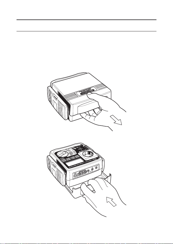
2. Procedure of removing cover
KEW 6201A have a dedicated cover to protect against an impact from the
outside and prevent the operation part, the LCD, and the connector socket
from becoming dirty. The cover can be detached and put on the back side of
the main body during measurement.
2.1 Method of removing the cover
Fig. 1
2.2 Method of storing the cover
Fig. 2
—
3
—
Page 6

3. Product summary and explanation
3.1 Product summary
The KEW 6201A is a hand-held portable appliance tester, performing four
functions to ensure the Safety of Class I and Class II appliances. And also can
measure the mains voltage. Readings are displayed on a large liquid crystal
display (LCD) below which are three LEDs, light up in 2 color, 2 color LEDs
which unambiguously display a pass or fa
international standards.
This instrument is suitable for performing tests as required by the following
standards.
AS/NZS 3760: 2010 In-s ervice safety inspection and testin g of elect rical
equipment.
This instrument is designed to check the electrical safety of appliances of
Class I and Class II categories.
As a guide IEC standard define these two categories as foll
Class I : Applianc es which have a function al insulatio n t hr oughout and
an earth connected case. These are often described as earthed
appliances.
Class II: Appli ances which have both functional and additional insulation
where any metal parts cannot become Live under fault conditions.
3.2 Test Function
KEW6201A have following features.
Class I Test •Protective conductor resistance
SELECT Switch + Class I Test
Class
SELECT Switch + Class II Test
Extension Leads test •Protective conductor resistance
SELECT Switch +
Leakage Current Test •Leakage current measurement
Function Tests of contents
•Insulation (250V or 500V)
•Protective conductor resistance
II
Test •Insulation (250V or 500V)
Extension Leads test
•Leakage Current test
•Leakage Current test
•Insulation P/N-PE
•Polarity
•Protective conducto
•Leakage Current test
il indication for results dictated by
ows:
r resistance
—
4
—
Page 7
3.3 Features
• Warning for the appliance to be ON.
• Selection for 250V or 500V on the insulation resistance test.
• Null function for the protective conductor resistance test.
• Warning for the over range value in the LCD.
• Capable of judging pass/fail of tests by LED on the panel and by buzzer.
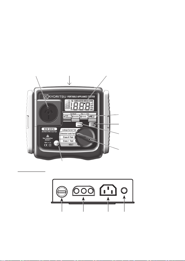
3.4 INSTRUMENTS LAYOUT
⑴ Test socket ⑵ Terminal block ⑹ LCD
Fig. 3
⑺ LED for test result
⑻ Start/Stop switch
⑼ Null/250V-500V
switch
⑽ Function switch
Terminal Block
⑿ ⑶ ⑷ ⑸
⑴ Test socket
Insert the mains plug of
conductor resistance, insulation resistance and Leakage current test.
⑾ SELECT switch
DUT to this socket for the polarity test of protective
—
5
—
Page 8

⑵ Terminal block
Connect the attached mains cord and Test Leads to this terminal block.
⑶ Terminal for mains cord
This terminal is connected to a mains supply via M7123.
⑷ Terminal for Extension leads adaptor
It corresponds to L, N, E of test socket, and the extension leads adaptor
(M-7140) connected with the cord reel to be plugged to it.
⑸ PE-probe terminal
Connect the Test Lead with all
the measurement of protective conductor resistance, and clip the metal
parts of DUT with the alligator clip.
⑹ LCD
Measured value is displayed
⑺ LED for test result
When the value of prot ect ive con du cto r resis tan ce a nd in su lat ion
resistance exceeds the limit dictated by applicable standards, LED lights up
in red. When it is within the limit, LED lig
⑻ Start/Stop switch
A measurement starts by pressing this switch.
Pressing the Start/Stop Switch again during Leakage Current Test stops
measurements.
⑼ Null/250V-500V switch
• Class I test measurement
It is used in o rder to push the Nul l button before protection earth
resistance measurement and to cancel the resistance of a test leads.
• Class II test measurement
The test voltage of insulation resistance is changed to 500V and 250V.
⑽ Function switch
Select a function with this switch.
⑾ SELECT switch
When the function is set under
will b e ac tu all y op er at ed t o measu re a le aka ge c urren t inst ead of
measuring insulation.
igator clip (M-7129A)(13) to this terminal for
hts up in green.
SELECT
switch is pressed, the appliance
—
6
—
Page 9
⑿ Fuse
Protected by a fuse of 600V/10A ceramic fuse (F type Φ6.3x32mm).
User can replace this fuse.
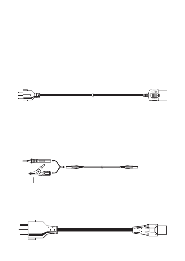
⒀ Mains cord (AU) M-7123
Thi s m ains cord c an be connect ed to the mains s up pl y so that the
instrument can derive power from it. To measure contact current, the
socket of the main power supply is to be equipped with an earth terminal.
Fig. 4
⒁ Test Lead with safety alligator clip(M-7129A) and Probe
Prod(M-7161A).The adapter of a tip part is exchangeable for an alligator
clip and a test stick type.
Please use it according to a measurement use.
Fig. 5
Probe with Blade Type Prod
Safety Alligator Clip
⒂ Extension leads adaptor(M-7140)
This is for connecting the instrument and a cord reel.
Fig. 6
—
7
—
with Blade type
Page 10

3.5 Explanation for indications
LCD Display
Over temperature warning
Power supply voltage
(Line-Neutral) indication
Fig. 7
Insulation measurement voltage
Note) Over range display: OL is displayed on the LCD.
Display symbols
DUT is OFF. Represents LN-E.
Null indication
Unit indication
Wh en l eak ag e cur ren t
test is interrupted.
Re pre sen t s Pro tec t iv e
conductor resistance
Repr es ent s the tes t is
fail.
The temperature sensor monitors overheating of the transformer.
When the overheat symbol appears on the LCD screen the unit
wil l ceas e to op era te until it coo ls down to normal operat ing
temperature and the overheat symbol disappears from the screen.
Normal operation then resumes.
R e p r es en t s le a k ag e
current.
D u r i ng t he DU T is
operated at the leakage
current test.
Display prompt the user
to set the D UT s wit ch
on.
3.6 Applicable standards
Instrument operation
AS/ NZS 3760: 2010 I n- ser vi ce s afety inspe ct ion and test ing of
trical equipment.
elec
Safety: IEC/EN61010-1 CAT.III 300V-instrument
IEC/EN61010-031 CAT.III 300V(600V)-test lead
—
8
—
Page 11

4. Specification
4.1 General specification, measuring range and accuracy
Voltage(VOLT) measurement of main power supply
Measuring range 207 ~ 264V AC
Resolution 1V
Accuracy ± (2%rdg+3dgt)
Measurement of Protective conductor resistance(RPE)
Measuring range 0 ~ 15.00Ω
Resolution 10mΩ
Open-circuit voltage <AC12V
Measuring current 10A AC nominal value
Accuracy ± (3%rdg+5dgt)
Measurement of Insulation resistance (RINS)
Rating 250V/20MΩ and 500V / 20MΩ
Measuring range 0.1~19.99MΩ
Resolution 10kΩ
Rated voltage 250V/500V DC(+20%/-10%) @1MΩ
Short-circuit current 2.5mA DC or less
Accuracy ± (2% rdg+3dgt)
Leakage current test
Measuring range AC0.1~ 19.99mArms
Resolution 0.01mA
Accuracy ±(3%rdg ± 5dgt)
Examination time Max 15 seconds
Note: For MOV appliances use Leakage Current test.
4.2 Threshold and display
Equipment
Class I RPE
Class II RINS
Extension Leads RPE
Protective conductor
resistance
<
1Ω RINS
=
<
1Ω RINS
=
Insulation
resistance
>
1MΩ IEL
=
>
1MΩ IEL
=
>
1MΩ IEL
=
Leakage
current
<
5mA
=
<
1mA
=
<
1mA
=
—
9
—
Page 12

4.3 Reference test condition
Unless otherwise specified, this specification is dependent on following
condition.
⑴ Ambient temperature: 23±5˚C
⑵ Relative humidity: 45 ~ 75%
⑶ Attitude: Horizontal
⑷ AC power supply: 240V, 50Hz
⑸ Altitude: 2000m or less
Operating temperature and humidity range
0℃ ~ +40℃ Relative humidity: 85% or less (no condensation)
Storage temperature and humidi
-20℃ ~ +60℃ Relative humidity: 85% or less (no condensation)
Rate voltage and frequency
Rated voltage: 240V ±10%
Rated frequency: 50 Hz ±1%
Maximum rated power
Approx. 9VA
Outer dimension and weight
Outer dimension: 185(L) × 167(W) × 89(D)mm
Weight: Approx. 1.2kg (only the instrument body)
Symbols used on the instrument:
Equipmen t pro tected t hroughout by DOUBLE I NSUL
REINFORCED INSULATION
Caution (Refer to the accompanying instruction manual)
#
ty range
—
10
ATION or
—
Page 13

5. Preparation before a measurement
5.1 Visual inspection
Before starting a measurement, user should undertake visual checks on
the mains cord, case and that the correct type and rated fuse is fitted to
the DUT. And also there should be no evidence of damage of a nature
that may impair the electrical safety of the item.
5.2 Connection to main power supply
5.2.1 Connection of mains cord
Set the Function switch to VOLT Function, and connect the mains supply
and the instrument with M7123 mains cord.
Fig. 8
M7123
CAUTION
• Always be sure to check there is no abnormal conditions or damages
on the instrument and cords. If any evidence of abnormality found,
measurement shall be stopped immediately.
• The outlet of main power supply must have earth terminal.
• This instrument can be only connected
240V+10%-10%, 50Hz.
5.2.2 Check the power supply voltage
There is no power switch and the instrument is immediately ready for
use. Power supply voltage is displayed on the LCD. Please check the
value, and when it is from 216V to 264V, the instrument can perform
correct measurements. If the displayed value is out of above range, do
not make a measurement.
#
to the commercial power of
—
11
—
Page 14

WARNING
M-7129A
• When the voltage of main power supply is 265V or more, HI-V is
displayed on the LCD.
• In that case, disconnect the mains cord of the instrument from main
power supply.
5.2.3 Null setting
A criteria of judgment for Earth Continuity is 1Ω, and it is low value.
So even the resistance of Test Leads will affect the measurement result.
This instrument, M-6201A, can cancel the resistance of Test lead by
pressing Null|250V/500V
shown below.
The Null fu nct ion is not re leased even if power off the instrument,
therefore, there's no need to do Null setting at every measurement.
However, when replacing fuses or test leads, it is recommended to do
Null setting again.
Procedure:
⑴ Set the function switch to Class I Test function.
⑵
Connect the mains supply and the instrument with M7123 mains cord.
#
sw itch. The procedure of Null setting is
Fig. 9
⑶ Insert Test Lead with safety alligator clip (M-7129A) in to the E terminal
of the instrument, and contact the tip of the Test Lead with the metal
parts of the socket on the instrument.
—
12
—
Page 15

Press Null|250V/500V switch with contacting the Test Lead and the
metal parts, the resistance of Test Lead will be displayed on the LCD as
shown above fig.10 for 2sec.
Then, the instrument cancels the resistance value of Test Lead and
adjust the displayed value to 0.00 as shown below fig.10.
At this bout,
Null setting cannot be done when a resistance is 3Ω or more.
A message no appears to indicate a resistance is exceeding the Null
setting range.
Display at Null setting
Fig. 10
NULL mark is displayed in the LCD.
⑷ Null setting can be released by pressing Null|250V/500V
2sec. The
released.
Null setting and release can be done on Class I Test function only.
5.2.4 Voltage setting for insulation resistance measurement
(How to change 250V and 500V)
⑴ Set t he func tio n sw itc h to Cla ss I I Test func tio n, a nd p res s the
Null|250V/500V
voltage is shown on the LCD. By pressing Null|250V/500V
250V and 500V can be changed over.
NULL mark on the LCD will disappear when Null setting is
swi tc h. Then the mark to indicate t he sel ec te d
Fig. 11
—
13
—
switch for
switch,
Page 16

6. Measuring method
6.1 Class I Test
The purpose of the test carried out for Class I appliances is to check the
insulation resistance between accessible conductive parts and connection
of protective earth and between live wire parts and accessible conductive
parts is within the range defined in the standards. To conduct the tests of
protective conductor resistance and insulation resistance for
the m ai ns plu g o f DUT t o the t es t socket (1) descri be d in clau se 3.4.
INSTRUMENTS LAYOUT and PE probe terminal (5).
Use the following setups, depending upon the type of DUT.
Clip except for the part which
Fig. 12
rotates or be heated.
DUT, connect
Switch ON the power.
—
14
—
Page 17

Class I Test Flowchart
⑴. Protective conductor resistance.
RPE
<
=
1Ω?
⑵.Appliance switch test
(3). Insulation resistance between L/N and PE.
LnE
>
=
1MΩ?
Light up in red
no →Con→value will
be repeated on the LCD.
Light up in red
no →LnE→value will
be repeated on the LCD.
Value (1). and (3). will be
alternately displayed on LCD
When the resistance between
LN is about 100kΩ or more
no →OFF is displayed
alternately on the LCD.
No
No
No
Yes
Yes
Yes
PASS
Light up in green
Light up in green
Is the Switch
turning on?
Start
• Shor t-circuit between L /N and PE is doubt w hen "no" and "OFF"
appears on the LCD in turns at the insulation resistance measurement
of the Extension leads test for Class I & II while DUT is on. Testing
should be immediately suspended.
• Follow the procedure described in 5.2-3 and do NULL setting before a
measurement.
• Alligator clip must make good contact w
• When the terminal is open or the resistance value exceeds measuring
range, OL mark (over range display) appears on the LCD.
• Do not touch the device under test while testing is in progress. Since
a high voltage of 500V, user may get electrical shock.
CAUTION
#
—
15
ith the enclosure of the DUT.
—
Page 18

6.2 Class I Test (Select the Leakage current test)
(1). Protective conductor resistance.
RPE
<
=
1Ω?
(2). Power on Leakage current test.
LEA
<
=
5mA?
Light up in red
no →Con→value will
be repeated on the LCD.
Light up in red
Stop the test and
no →LEA→value will
be repeated on the LCD.
Value of (1). and (2). will be
alternately displayed on the LCD.
No
No
Yes
Yes
PASS
Light up in green
Light up in green
Brief indicationsS-andonwill be displayed
in turns on the LCD for 5 sec and prompt the
user to set the DUT switch on.
Then a mark indicating working DUT function
will be displayed for 10 sec.
5sec
10sec
Selecting Class I test while Select Switch is being pressed down initiates
Leakage current test instead of Insulation resistance test.
In case of selecting Leakage current test, metal parts other than the heating
or movable parts must be clipped with Test Lead M-7129A since the DUT
activates. Pressing the START/STOP
stops the test immediately. To restart the test, press the START/STOP
switch again 2 sec or later than the stop of the test. Then (1) Protective
conductor resistance will be restarted.
Fig 12 indicates how to connect the devices.
Class I Test (Select the Leakage current test) Flowchart
Start
switch during Leakage current test
—
16
—
Page 19

CAUTION
• When the terminal is open or the resistance value exceeds measuring
range, OL mark (over range display) appears on the LCD.
• The test will stop. A message Stp appears on the LCD but values of
Leakage current aren't displayed.
• Operate a device and measure the leakage current flowing on it at
Leakage current test function. Care should be taken not to touch with
ting or movable parts during tests. Extra care should also be
the hea
taken to light and heat generated by the device.
• Firmly insert the plugs of DUT to the AU socket of this instrument.
Plugs may be he at ed if Leakage curre nt test is performed with
improper connection.
• Do not connect/remove the plugs during Leakage current test. It may
cause reading error. Do not use the instrument on the device which
has a power of 2kVA or more.
6.3 Class Ⅱ Test
The Class Ⅱ appliances have the indication of DOUBLE INSULATION
or the symbol of . Double insulation test is to check the insulation
resistance of the appliances is within the range defined in the standards.
Fig. 13
#
WARNING
#
Switch ON the power.
—
17
—
Page 20

Class II Test Flowchart
(1). Appliance switch test
Is the Switch
turning on?
(2). Insulation resistance between L/N and PE.
LnE
>
=
1MΩ?
When the resistance between
LN is about 100kΩ or more
no →OFF is displayed
alternately on the LCD.
Light up in red
no →LnE→value will
be repeated on the LCD.
Value of (2). will be
displayed on the LCD.
No
No
Yes
Yes
PASS
Light up in green
Light up in green
Start
CAUTION
• Shor t-circuit between L /N and PE is doubt w hen "no" and "OFF"
appears on the LCD in turns at the insulation resistance measurement
of the Extension leads test for Class I & II while DUT is on. Testing
should be immediately suspended.
• When the terminal is open or the resistance value exceeds measuring
• Do not touch the device under test while testing is in progress. Since
6.4 ClassⅡTest (Select the Leakage current test)
When the function is set to Class II test while pressing Select switch, Power
on leakage current test will be carried out instead of Insulation resistance
test. When Leakage current test is chosen, DUT will operate actua
metal part of the machine tool except for the rotating part with Test Lead
M-7129A. In order to stop testing the leakage current while measuring, press
START/STOP
2 seconds or more from the stop. The test will be restart.
range, OL mark (over range display) appears on the LC
a high voltage of 500V, user may get electrical shock.
. To start a test again, press
#
—
18
START/STOP
—
again after about
D.
lly. Clip a
Page 21

Class II Test (Select the Leakage current test) Flowchart
Power on Leakage current test.
LEA
<
=
1mA ?
Light up in red
Stop the test and
no →LEA→value will
be repeated on the LCD.
Value will be displayed on the LCD.
No
Yes
PASS
Light up in green
Brief indicationsS-and onwill be displayed
in turns on the LCD for 5 sec and prompt the
user to set the DUT switch on.
Then a mark indicating working DUT function
will be displayed for 10 sec.
5sec
10sec
Start
CAUTION
• When the terminal is open or the resistance value exceeds measuring
range, OL mark (over range display) appears on the LCD.
• The test will stop. A message Stp appears on the LCD but values of
Leakage current aren't displayed.
#
• Operate a device and measure the leakage current flowing on it at
Leakage current
the heating or movable parts during tests. Extra care should also be
taken to light and heat generated by the device.
• Firmly insert the plugs of DUT to the AU socket of this instrument.
Plugs may be he at ed if Leakage curre nt test is performed with
improper connection.
• Do not connect/remove the plugs during Leakage current test. It may
e reading error. Do not use the instrument on the device which
caus
has a power of 2kVA or more.
test function. Care should be taken not to touch with
WARNING
#
—
19
—
Page 22

6.5 Extension Leads Test
• This test is for extension leads, and check:
• Protective conductor resistance between accessible conductive parts and
connection of protective earth.
• Insulation resistance between L/N and PE.
• Polarity check of the Line and Neutral terminal of plug and socket.
Test procedure and the connection are as follows.
Fig. 14
—
20
—
Page 23

Extension Leads Test Flowchart
(1). Protective conductor resistance test.
RPE
<
=
1Ω?
(2). Insulation resistance test between L/N and PE.
(3). Polarity test between L-L and N-N.
L-L & N-N
<
=
10Ω?
Light up in red
no →Con→value will
be repeated on the LCD.
Light up in red
no →LnE→value will
be repeated on the LCD.
Light up in red
no →L-L →value or
no →n-n →value will
be repeated on the LCD.
Value of (1) and (2) will be
alternately displayed on LCD.
No
No
No
Yes
Yes
Yes
PASS
Light up in green
Light up in green
LnE
>
=
1MΩ?
Start
• Shor t-circuit between L /N and PE is doubt w hen "no" and "OFF"
appears on the LCD in turns at the insulation resistance measurement
of the Extension leads test for Class I & II while DUT is on. Testing
should be immediately suspended.
• Follow the procedure described in 5.2-3 and do Null setting before a
measurement.
• When the terminal is open or
range, OL mark (over range display) appears on the LCD.
• Do not touch the device under test while testing is in progress. Since
a high voltage of 500V, user may get electrical shock.
CAUTION
#
the resistance value exceeds measuring
—
21
—
Page 24

• When the fun ction is set to extension leads test while pressing Select
(1). Protective conductor resistance test.
RPE
<
=
1Ω?
(2). Power on Leakage current test
LEA
<
=
1mA?
Light up in red
no →Con→value will
be repeated on the LCD.
Light up in red
Stop the test and
no →LEA→value will
be repeated on the LCD.
Value of (1). and (2). will be
alternately displayed on the LCD.
No
No
Yes
Yes
PASS
Light up in green
Light up in green
Brief indicationsS-andonwill be displayed
in turns on the LCD for 5 sec and prompt the
user to set the DUT switch on.
Then a mark indicating working DUT function
will be displayed for 10 sec.
5sec
10sec
switch, Power on le akage current t es t will be ca rr ie d out ins te ad of
Insulation resistance test.
・ Protective conductor resistance between accessible conductive parts and
connection of protective earth.
Leakage Current test: Measure a leakage current by actually operating
・
the appliance.
Extension Leads Test (Select the
Start
Leakage current test) Flowchart
• When the terminal is open or the resistance value exceeds measuring
range, OL mark (over range display) appears on the LCD.
• The test will stop. A message Stp appears on the LCD but values of
Leakage current aren't displayed.
CAUTION
#
—
22
—
Page 25

WARNING
LEA
<
=
20mA?
Stop the test and OL will
be displayed on the LCD.
Value of leakage current will
be displayed on the LCD.
Yes
No
Brief indications "S-" and "on" will be
displayed in turns on the LCD for 5 sec and
prompt the user to set the DUT switch on.
Then a mark indicating working DUT function
will be displayed for 10 sec.
5sec
10sec
• Operate a device and measure the leakage current flowing on it at
Leakage current test function. Care should be taken not to touch with
the heating or movable parts during tests. Extra care should also be
taken to light and heat generated by the device.
• Firmly insert the plugs of DUT to the AU socket of this instrument.
Plugs may be he at ed if Leakage curre nt test is performed with
improper connection.
• Do not connect/remove the plugs during Leakage current test. It may
cause reading error. Do not use the instrument on the device which
has a power of 2kVA or more.
6.6 Leakage Current Test
This function is to conduct the leakage current test separately with DUT
operating actually. A leakage current only will be displayed on the LCD after
DUT is electrified for 15 seconds.
D will not light on even the Class I, Class II thresholds are exceeded.
LE
• Set the function switch to Leakage Current Test position.
• Refer to the Fig12 or Fig13 for connection of an appliance.
• After set up is done, press
• Check the switch of DUT is ON.
• DUT will operate for 15 seconds, and the maximum value of the leakage
current will be displayed on the LCD. If the leakage from the DUT is
greater than 20mA then the 6201A should immediately stop the test.
• In order to stop the Leakage Current Test, press
again. The test will stop. A message Stp appears on the LCD but values
of Leakage current aren't displayed.
Leakage Current Measment Flowchart
START
#
START/STOP
—
23
switch.
—
START/STOP
switch
Page 26

WARNING
• Operate a device and measure the leakage current flowing on it at
Leakage current test function. Care should be taken not to touch with
the heating or movable parts during tests. Extra care should also be
taken to light and heat generated by the device.
• Firmly insert the plugs of DUT to the AU socket of this instrument.
Plugs may be he at ed if Leakage curre nt test is performed with
improper connection.
• Do not connect/remove the plugs during Leakage current test. It may
cause reading error. Do not use the instrument on the device which
has a power of 2kVA or more.
#
7. Fuse replacement
When the fuse blows during use, please replace with new one according to
below procedure.
Fig. 15
⑴ Use a flat head screwdriver and turn it about 45º to left and remove the
fuse cap and fuse.
⑵ Remove
⑶ Install the fuse cap and fuse again. At that point, the screwdriver groove
(The screwdriver groove will stop at the horizontal position.)
the fuse from the fuse cap and replace it with new one.
shall be at about 45º turned to left from the initial position. Use the flat
head screwdriver and turn it to right.
—
24
—
Page 27

WARNING
Be sure to remove mains cord from the instrument before replacing fuse.
•
• The fuse that user can replace is this fuse only. Never attempt to
perform the other repairing.
• Plea se use th e speci fie d fuse (F ast act ing typ e cer am ic fuse:
600V/10A - Φ6.3x32mm).
For the specified fuse, purchase it by yourself or order it from our agency.
•
8. Services
If this instrument should fail
Please remember to give all the information possible concerning the nature of
the fault, as this will mean that the instrument will be serviced and returned
to you more quickly.
#
CAUTION
#
to operate correctly, return it to your distributor.
9. Case and strap assembly
Strap belt and probe case can be attached to the instrument as below.
Pass the strap belt down through the side panel of the main body from t
top, and up through the slots of the probe form the bottom. (Fig. 16).
Pass the strap through the buckle, adjust the strap for length and secure.
Fig. 16
he
—
25
—
Page 28

DISTRIBUTOR
Kyoritsu reserves the rights to change specifications or designs
described in this manual without notice and without obligations.
92-1843C 7-11
 Loading...