

Page 1
INSTRUCTIONMANUAL
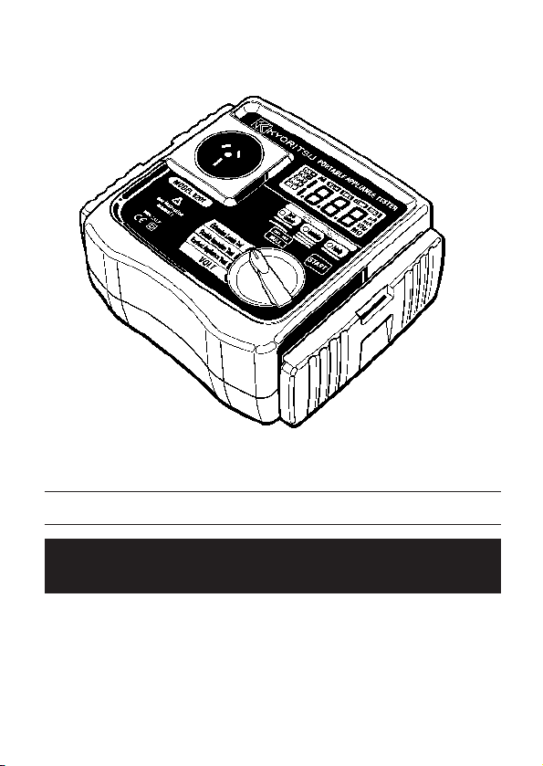
PORTABLEAPPLIANCETESTER
MODEL 6201
KYORITSUELECTRICALINSTRUMENTS
WORKS,LTD.
Page 2

CONTENTS
1.Safe testing .....................................................................................1
2. Procedure of removing cover .........................................................3
2.1 Method of removing the cover ..................................................3
2.2 Method of storing the cover ......................................................3
3. Product summary and explanation .................................................4
3.1 Product summary ..................................................................... 4
3.2 Test range .................................................................................4
3.3 Features ................................................................................... 5
3.4 Instrument layout ......................................................................5
3.5 Explanation for indications ........................................................8
3.5.1 LCD Display ..........................................................................8
3.5.2 LED for threshold value indication and buzzer .....................8
3.6 Applicable standards ..................................................................8
4. Specification ................................................................................. 9
5. Preparation before a measurement ............................................... 11
5.1 Visual inspection ........................................................................ 11
5.2 Connection to main power supply ..............................................11
5.2.1 Connection of mains cord .....................................................11
5.2.2 Check the power supply voltage .......................................... 11
5.2.3 NULL setting (Protective conductor resistance range) .........12
5.2.4 Voltage setting for insulation resistance measurement ........13
6. Measuring method .........................................................................14
6.1 Earthed appliance Test ..............................................................14
6.2 Double Insulation Test ................................................................16
6.3 Extension Leads Test .................................................................17
7. Fuse replacement ..........................................................................19
8. Services .........................................................................................20
9. Case and strap assembly ..............................................................21
Page 3
1.Safetesting
!
!
!!!
!
Electricity is dangerous and can cause injury and death. Always treat it with the
greatest of respectand care. If you are not quite sure how to proceed, stop a
measurement and take advice from a qualified person.
This instruction manual ontains warning and safety rules which must be
observed by the user to ensure safe operation of the instrument and retain it in
safe condition. Therefore, read through these operating instructions before
using the instrument.
IMPORTANT:
This instrument must only be used by a competent and trained person and
operated in strict accordance with the instructions.
KYORITSU will not accept liability for any damage or injury caused by misuse
or non-compliance with the instructions or with the safety procedures.
It is essential to read and to understand the safety rules contained in the
instructions or with the safety procedures.
The symbol indicated on the instrument means that the user must refer
to the related sections in the manual for safe operation of the instrument.
DANGER is reserved for conditions and actions that are likely to
cause serious or fatal injury.
WARNING is reserved for conditions and actions that can cause
serious or fatal injury.
CAUTION is reserved for conditions and actions that can cause
minor injury or instrument damage.
Be sure to carefully read instructions following each symbol in
this manual.
―1―
Page 4
DANGER
!
!
!
!
● This instrument can be connected only to the commercial power of
240V+10%-10%, 50Hz.
● For safety reasons, only use the Test Leads designed to be used with
this instrument and recommended by KYORITSU.
● Use only grounded mains outlets to supply the instrument.
Do not touch the device under test while testing is in progress.
● Since a high voltage of 500V is outputting continuously, especially while
measuring insulation resistance, user may get electrical shock.
Also not to touch the capacitor of the device under test as hazardous
voltage may exist.
● When testing, always be sure to keep your fingers behind the safety
barriers on the test leads.
● Disconnect the instrument from the power supply when measurement is
finished.
Do not leave the instrument with connected to the power supply.
WARNING
● Never open the instrument case - because dangerous voltages are
present. Only fully trained and competent electrical engineers should open
the case.
● If abnormal conditions of any sort are noted (such as a faulty display,
unexpected readings, broken case, cracked test leads, etc.)do not use
the instrument and return it to your distributor for inspection and repair.
Never attempt to use the instrument if the instrument or your hand is wet.
CAUTION
● When using Test Leads with alligator clip, be sure to check the alligator
clip is firmly connected to the metal part of the device under test.
Otherwise, inaccurate measurement or arc at the contacts may occurs.
● The rated measuring voltage for insulation test is 500V.DC.
For electrical devices to be tested, if this test voltage seems not proper to
apply, contact your distributor and ask for advices.
● When testing faulty device, it may trip the circuit breaker of main power
supply during test and may cause interruption of service.
Be careful when the same main power supply is used for PCs.
● We are not liable for loss of data on PC during testing with this
instrument. The device under test is powered on during most tests,
but please turn it to OFF position after use. Use a cloth dipped in water or
neutral detergent for cleaning the instrument.
Do not use abrasives or solvents.
―2―
Page 5
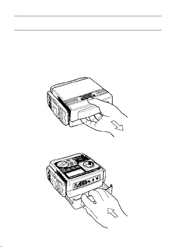
2. Procedureofremovingcover
Model 6201 have a dedicated cover to protect against an impact from the
outside and prevent the operation part, the LCD, and the connector socket from
becoming dirty. The cover can be detached and put on the back side of the
main body during measurement.
2.1 Methodofremovingthecover
Fig.1
2.2 Methodofstoringthecover
Fig.2
―3―
Page 6

3. Productsummaryandexplanation
3.1 Productsummary
The Model 6201 is a hand-held portable appliance tester, performing four
functions to ensure the Safety of Class I and Class II appliances. And also can
measure the mains voltage. Readings are displayed on a large liquid crystal
display(LCD) below which are three LEDs, light up in 2color, 2 color LEDs which
unambiguously display a pass or fail indication for results dictated by
international standards.
This instrument is suitable for performing tests as required by the following
standards.
AS/NZS 3760: 2001 In-service safety inspection and testing of electrical
equipment.
This instrument is designed to check the electrical safety of appliances of Class
I and Class II categories.
As a guide IEC standard define these two categories as follows:
Class 1:Appliances which have a functional insulation throughout and an
earth connected case. These are often described as earthed
appliances.
Class 2:Appliances which have both functional and additional insulation
where any metal parts cannot become "Live" under fault conditions.
3.2 Testrange
MODEL 6201 have following features.
Range
Earthed Appliance test
(Class 1 appliance)
Double Insulation test
(Class 2 appliance)
Extension Leads test
(1) Protective conductor resistance
(2) Insulation
(1) Insulation
(1) Protective conductor resistance
(2) Insulation L-N and L/N-PE
(3) Polarity
Tests
―4―
Page 7
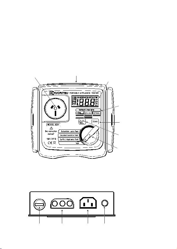
(1)Testsocket
(2)Terminalblock
(6)LCD
(7)LEDfortestresult
(8)Startswitch
(9)Null/250V-500V
switch
(10)Rangeswitch
(11) (3) (4) (5)
3.3 Features
* Compact, light weight and truly portable
* Robust Panel and Case
* Capable of measuring the voltage of main power supply
* Large custom digital display
* Capable of judging pass/fail of tests by LED on the panel and by buzzer.
3.4 Instrumentlayout(Illust:M-6201)
Terminal Block
Fig. 3
―5―
Page 8

(1)Testsocket
Insert the mains plug of DUT to this socket for the polarity test of protective
conductor resistance, insulation resistance and Extension leads.
(2)Terminal block
Connect the attached mains cord and Test Leads to this terminal block.
(3)Terminal for mains cord
This terminal is connected to a mains supply via M7123.
(4)Terminal for Extension leads adaptor
It corresponds to L, N, E of test socket, and the extension leads adaptor(M-
7140) connected with the cord reel to be plugged to it.
(5)Rpe terminal
Connect the Test Lead with alligator clip(M7129)(13) to this terminal for the
measurement of protective conductor resistance, and clip the metal parts of
DUT with the alligator clip.
(6)LCD
Measured value is displayed.
(7) LED for test result
When the value of protective conductor resistance and insulation resistance
exceeds the limit dictated by applicable standards, LED lights up in red.
When it is within the limit, LED lights up in green.
(8)Start switch
A measurement starts by pressing this switch.
(9)NULL/250V-500V switch
● Earthed appliance test measurementIt is used in order to push the
NULL button before protection earth resistance measurement and to
cancel the resistance of a test leads.
● Double insulation test measurement
The test voltage of insulation resistance is changed to 500V and 250V.
(10)Range switch
Select a range with this switch.
―6―
Page 9

(11)Fuse
Protected by a fuse of 600V/500mA ceramic fuse (F type Φ6.3x32mm).
User can replace this fuse.
(12)Mains cord(AU) M-7123
This mains cord can be connected to the mains supply so that the
instrument can derive power from it. To measure contact current, the socket
of the main power supply is to be equipped with an earth terminal.
Fig.4
(13)Test Lead with safety alligator clip(M-7129) and Probe with Blade type
Prod(M-7101).The adapter of a tip part is exchangeable for analligator clip
and a test stick type.
Please use it according to a measurement use.
Probe wIth Blade Type Prod
Safety Alligator Clip
(14)Extension leads adaptor(M-7140)
This is for connecting the instrument and a cord reel.
Fig.5
Fig.6
―7―
Page 10

3.5 Explanationforindications
3.5.1LCDDisplay
Insulationmeasurementvoltage
Powersupplyvoltage
(Line-Neutral)indication
Fig.7
Note) Over range display: "OL" is displayed on the LCD.
3.5.2LEDforthresholdvalueindicationandbuzzer
Range Status LED Color
Earth
Continuity
Insulation
Polarity(L/N/PE)
RPE < 1
Ω
RPE ≧ 1
Ω
RINS ≧ 1M
RINS < 1M
Correct wiring
Faulty wiring
Green
Red
Green
Ω
Ω
Red
Green
Red
3.6Applicablestandards
Instrument operation
AS/NZS 3760: 2001 In-service safety inspection and testing of
electrical equipment.
NULLindication
Unitindication
Warning buzzer
(Continuous sounds)
---
ON
---
ON
---
ON
Safety: IEC/EN61010-1 CAT.III 300V-instrument
IEC/EN61010-2-031 CAT.III 300V(600V)-test lead
―8―
Page 11

4. Specification
● General specification, measuring range and accuracy
Voltage(VOLT) measurement of main power supply
Measuring range
Resolution
Accuracy
207 ~ 264V AC
1V
± (2%rdg+3dgt)
Measurement of Protective conductor resistance(RPE)
Measuring range
Resolution
Open-circuit voltage
Measuring current
Accuracy
0 ~ 19.99
Ω
10m
Ω
5.0±0.4V DC
±
Within 200 ~ 250mA DC
(when measuring 0 ~ 2
(2%rdg+3dgt)
±
Measurement of Insulation resistance (RINS)
Rating
Measuring range
Resolution
Rated voltage
Short-circuit current
Accuracy
250V/200MΩ and 500V / 200MΩ
0~19.99MΩ/ 199.9MΩ (2 auto ranges)
10kΩ/100kΩ
250V/500V DC(+20%/-10%) @1MΩ
14mA DC or less
± (2% rdg+3dgt)
Threshold and display
Range Status LED Color
Earth
Continuity
Insulation
Polarity(L/N/PE)
RPE < 1
Ω
RPE ≧ 1
Ω
RINS ≧ 1M
RINS < 1M
Correct wiring
Faulty wiring
Green
Red
Green
Ω
Ω
Red
Green
Red
―9―
Ω
Warning buzzer
(Continuous sounds)
---
ON
---
ON
---
ON
Page 12

Reference test condition
!
Unless otherwise specified, this specification is dependent on following
condition.
(1) Ambient temperature: 23±5℃
(2) Relative humidity: 45 ~ 75%
(3) Attitude: Horizontal
(4) AC power supply: 240V, 50Hz
(5) Altitude: 2000m or less
Operating temperature and humidity range
0℃ ~ +40℃ Relative humidity: 85% or less(no condensation)
Storage temperature and humidity range
-20℃ ~ +60℃ Relative humidity: 85% or less(no condensation)
Rate voltage and frequency
Rated voltage: 240V ±10%
Rated frequency: 50Hz ±1%
Maximum rated power
Approx. 7VA
Outer dimension and weight
Outer dimension: 185(L) × 167(W) × 89(D)mm
Weight: Approx. 1kg (only the instrument body)
Symbols used on the instrument:
F Equipment protected throughout by DOUBLE INSULATION or
REINFORCED INSULATION
Caution (Refer to the accompanying instruction manual)
―10―
Page 13

!
5. Preparationbeforeameasurement
5.1 Visualinspection
Before starting a measurement, user should undertake visual checks on
the mains cord, case and that the correct type and rated fuse is fitted to
the DUT. And also there should be no evidence of damage of a nature
that may impair the electrical safety of the item.
5.2 Connectiontomainpowersupply
5.2.1 Connectionofmainscord
Set the range switch to VOLT range, and connect the mains supply and the
instrument with M7123 mains cord.
M7123
Fig.8
● Always be sure to check there is no abnormal conditions or damages on
CAUTION
the instrument and cords. If any evidence of abnormality found,
measurement shall be stopped immediately.
● The outlet of mains power supply must have earth terminal.
● This instrument can be only connected to the commercial power of
240V+10%-10%, 50Hz.
5.2.2Checkthepowersupplyvoltage
There is no power switch and the instrument is immediately ready for use.
Power supply voltage is displayed on the LCD. Please check the value, and
when it is from 216V to 264V, the instrument can perform correct
measurements. If the displayed value is out of above range, do not make a
measurement.
―11―
Page 14

● When the voltage of mains power supply is 265V or more, "HI-V" is
!
WARNING
displayed on the LCD and buzzer sounds (discontinuous sounds). In that
case, disconnect the mains cord of the instrument from main power supply.
5.2.3 NULLsetting
Criteria of judgment for Earth Continuity is 1Ω, and it is low value.
So even the resistance of Test Leads will affect the measurement result.
This instrument, M-6201, can cancel the resistance of Test lead by pressing
250V/ 500V
switch. The procedure of NULL setting is shown below.
NULL
The NULL function is not released even if power off the instrument, therefore,
there's no need to do NULL setting at every measurement.
However, when replacing fuses or test leads, it is recommended to do NULL
setting again
Procedure:
(1) Set the range switch to Earth Appliance Test range.
(2) Connect the mains supply and the instrument with M7123 mains cord.
Fig.9
―12―
Page 15

(3) Insert Test Lead with safety alligator clip(M-7129) in to the E terminal of the
instrument, and contact the tip of the Test Lead with the metal parts of the
socket on the instrument.
Press start switch with contacting the Test Lead and the metal parts,the
resistance of Test Lead will be displayed on the LCD as shown above fig.10
for 2sec.
Then, the instrument cancels the resistance value of Test Lead and adjust
the displayed value to "0.00" as shown below fig.10.
At this bout, NULL mark is displayed in the LCD.
Display at NULL setting
Fig.10
(4) NULL setting can be released by pressing switch for 2sec.
The "NULL" mark on the LCD will disappear when NULL setting is released.
NULL setting and release can be done on Earthed Appliance Test range only.
5.2.4Voltagesettingforinsulationresistancemeasurement
(Howtochange250Vand500V)
(1) Set the range switch to Double Insulation range, and press the
switch.
Then the mark to indicate the selected voltage is shown on the LCD. By
pressing switch, 250V and 500V can be changed over.
250V/ 500V
NULL
250V/ 500V
NULL
250V/ 500V
NULL
h
250V/ 500V
NULL
Fig.11
―13―
Page 16

6. Measuringmethod
6.1EarthedapplianceTest
The purpose of the test carried out for Class 1 appliances is to check the
insulation resistance between accessible conductive parts and connection of
protective earth and between live wire parts and accessible conductive parts
is within the range defined in the standards.
To conduct the tests of protective conductor resistance and insulation
resistance for DUT, connect the mains plug of DUT to the test socket (1)
described in clause 3.4INSTRUMENTSLAYOUT and PE probe
terminal (5).
Use the following setups, depending upon the type of DUT.
Fig.12
(1) Power on the DUT
(2) Connect the mains plug of Safety class 1 DUT to test socket on the
instrument.
―14―
Page 17

(3) Connect Test Lead M-7129 to Rpe terminal and clip the metal part of DUT
!
with alligator clip.
(4) Press the START switch when above preparation is completed.
(5) First, measure the protective conductor resistance.
When it passes(1Ω or less), lights up in green and display the
○
Earth
Continuity
measured result on the LCD.
(6) Then the instrument automatically performs insulation resistance
measurement. When it passes(1MΩ or more), lights up in red
Insulation
○
and the measurement is completed. The measured values of protective
conductor resistance and insulation resistance, which are passed the test,
will be alternately displayed on the LCD.
Earth
(7) When it fails, or will light up in red, and "no" is
○
Continuity
Insulation
○
displayed on the LCD.
The measured value, which is failed the test, and the message "no" will be
alternately displayed on the LCD.
CAUTION
● Follow the procedure described in 5.2-3 and do NULL setting before a
measurement.
● Alligator clip must make good contact with the enclosure of the DUT.
● When the terminal is open or the resistance value exceeds measuring
range, "OL" mark (over range display) appears on the LCD.
● Do not touch the device under test while testing is in progress.
Since a high voltage of 500V, user may get electrical shock.
―15―
Page 18

6.2DoubleInsulationTest
The Class 2 appliances have the indication of "DOUBLE INSULATION"
or the symbol of F. Double insulation test is to check the insulation
resistance of the appliances is within the range defined in the standards.
Fig.13
(1) Power on the DUT
(2) Connect Test Lead M-7129 to Rpe terminal and clip the metal part
of DUT with alligator clip.
(3) Connect the mains plug of Safety class 2 DUT to test socket on the
instrument.
(4) Press the START switch when above preparation is completed.
(5) Measure the insulation resistance.
When it passes(1MΩ or more), lights up in green and
Insulation
○
the test is completed. The measured value, which is passed the test, will be
displayed on the LCD .
―16―
Page 19

● When the terminal is open or the resistance value exceeds measuring
!
CAUTION
range, "OL" mark (over range display) appears on the LCD.
● Do not touch the device under test while testing is in progress.
Since a high voltage of 500V, user may get electrical shock.
6.3ExtensionLeadsTest
This test is for extension leads, and check:
* Protective conductor
* Insulation resistance between L and N, and insulation resistance
between L/N and PE.
* Polarity check of the Line and Neutral terminal of plug and socket.
Test procedure and the connection are as follows.
Fig.14
―17―
Page 20

(1) Plug the extension leads adaptor M-7140 to the IEC socket of
!
M-6201 connector block.
(2) Connect the plug of the adaptor M-7140 for extension lead with the
connector of the extension lead.
(3) Insert the plug of extension lead into the socket on the front side of M-6201.
(4) Set the range switch on M-6201 to Extension Leads Test range, and
press the START switch.
(5) Then protective conductor resistance is measured.
When it passes(1Ω or less),lights up in green and display the measured
result on the LCD.
(6) Then the instrument automatically performs insulation resistance
measurement. When it passes(1MΩ or more), lights up in green
Insulation
○
and the measured result is displayed on the LCD.
(7) Polarity test will be performed the next, and when it passes,
○
Polarity
lights up in green and the measured values of protective
conductor resistance and insulation resistance will be alternately displayed
on the LCD .
Earth
(8) When it fails at any of three: , the
○
Continuity
Insulation
○
corresponding LED lights up in red and further measurement will be stopped.
The measured value, which is failed the test, and the message "no" will be
displayed on the LCD in turn.
CAUTION
● Follow the procedure described in 5.2-3 and do NULL setting before a
measurement.
● Alligator clip must make good contact with the enclosure of the DUT.
● When the terminal is open or the resistance value exceeds measuring
range, "OL" mark (over range display) appears on the LCD.
● Do not touch the device under test while testing is in progress.
Since a high voltage of 500V, user may get electrical shock.
―18―
○
Polarity
Page 21

!
!
7.Fusereplacement
When the fuse blows during use, please replace with new one according to
below procedure.
Fig.15
(1) Use a flat head screwdriver and turn it about 45°to left and remove the
fuse cap and fuse.
(2) Remove the fuse from the fuse cap and replace it with new one.
(3) Install the fuse cap and fuse again. At that point, the screwdriver groove
shall be at about 45°turned to left from the initial position. Use the flat
head screwdriver and turn it to right.
(The screwdriver groove will stop at the horizontal position.)
● Be sure to remove mains cord from the instrument before replacing fuse.
● The fuse that user can replace is this fuse only. Never attempt to perform
the other repairing.
CAUTION
● Please use the specified fuse
(Fast acting type ceramic fuse: 600V/500mA - Φ6.3×32mm).
For the specified fuse, purchase it by yourself or order it from our agency.
WARNING
―19―
Page 22

8. Services
If this instrument should fail to operate correctly, return it to your distributor.
Please remember to give all the information possible concerning the nature of
the fault, as this will mean that the instrument will be serviced and returned to
you more quickly.
―20―
Page 23

9. Caseandstrapassembly
Strap belt and probe case can be attached to the instrument as below.
Pass the strap belt down through the side panel of the main body from the top,
and up through the slots of the probe form the bottom. (Fig. 16).
Pass the strap through the buckle, adjust the strap for length and secure.
Fig.16
―21―
Page 24

DISTRIBUTOR
Kyoritsu reserves the rights to change specifications or designs
described in this manual without notice and without obligations.
92-1559 03-07
 Loading...