

Page 1
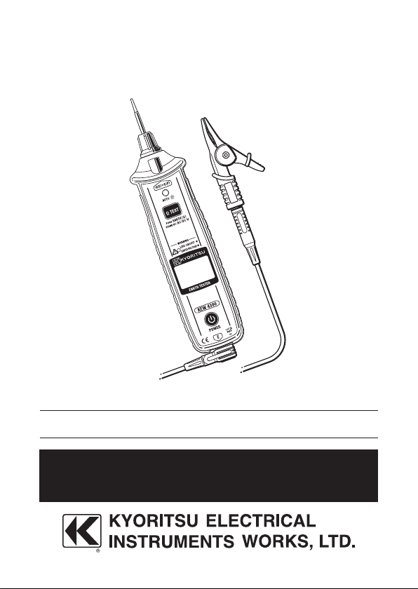
Instruction Manual
Simplified Earth Tester
KEW 4300
Page 2

Contents
1. Safety warnings
2. Features
3. Specification
4. Instrument layout
5. Accessories
6. Getting started
6-1 Battery voltage check
6-2 Attaching Metal tip/ adapter
7. Voltage measurement
7-1 Measurement procedure
7-2 Live circuit warning
8. Earth resistance measurement
8-1 Principle of measurement
8-2 Measurement procedure
9. LCD backlight and LED light
10. Replacing batteries
・・・・・・・・・・・・・・・・・・・・・・・・・・・・・・・・・・・・・・・・・
・・・・・・・・・・・・・・・・・・・・・・・・・・・・・・・・・・・・・・・・・・・・・・・
・・・・・・・・・・・・・・・・・・・・・・・・・・・・・・・・・・・・・・・・・・・・
・・・・・・・・・・・・・・・・・・・・・・・・・・・・・・・・・・・・・・・・
・・・・・・・・・・・・・・・・・・・・・・・・・・・・・・・・・・・・・・・・・・・・
・・・・・・・・・・・・・・・・・・・・・・・・・・・・・・・・・・・・・・・・・
・・・・・・・・・・・・・・・・・・・・・・・・・・・・・・・
・・・・・・・・・・・・・・・・・・・・・・・・・・・・・・・・・・・
・・・・・・・・・・・・・・・・・・・・・・
・・・・・・・・・・・・・・・・・・・・・・・・・・・・・・・・・
・・・・・・・・・・・・・・・・・・・・・・・・・・・・
・・・・・・・・・・・・・・・・・・・・・・・・・・・・・
・・・・・・・・・・・・・・・・・・・・・・・・・・・・・
・・・・・・・・・・・・・・・・・・・・・・・・・・・・・・・・・・・・
10
11
11
・・・・・・・・・・・・・・・・・・・・・・・・・・
・・・・・・・
・・・・・・・・・・・・・・・・・・・・・・・・・・・ 15
11
13
13
14
15
16
18
19
1
4
5
8
Page 3

1. Safety warnings
This instrument ha s been designe d, manufactured and t ested
according to IEC 61010-1: Safety requireme nts fo r Elec tronic
measuring apparatus, and delivered in the best condition after
passing quality control tests.
This instruction manual contains warnings and safety rules which
have to be observed by the user to ensure safe operation of the
instrument and to maintain it in safe condition. Therefore, read
through these operating instructions before using the instrument.
DANGER
● Read through and understand the instructions contained in this
manual before using the instrument.
● Keep the manual at hand to enable quick reference whenever
necessary.
● The instrument is to be used only in its intended applications.
● Understand and follow all the safety instructions contained in
the manual.
It is essential that the above instructions are adhered to. Failure
to follow the above instructions may cause injury, instrument
damage and/or damage to equipment under test.
The symbol # indicated on the instrument, means that the user
must refer to the related parts in the manual for safe operation of
the instrument. It is essential to read the instructions wherever the
symbol appears in the manual.
#
DANGER : is reserved for conditions and actions that are
#
likely to cause serious or fatal injury.
WARNING : is reserved for conditions and actions that can
#
cause serious or fatal injury.
CAUTION : is reserved for conditions and actions that can
#
cause injury or instrument damage.
#
1
Page 4

DANGER
#
● Never make measurement on a circuit in which the electrical
potential exceeds 300V.
● Do not attempt to make measurement in the presence of
flammable gasses. Otherwise, the use of the instrument may
cause sparking, which can lead to an explosion.
● Never attempt to use the instrument if its surface or your hand
is wet.
● Be careful not to short-circuit the power line with the metal
part of the test leads when measuring voltage. It may cause
personal injury.
● Do n ot exce e d th e ma x imum allowa b l e in p u t of any
measurement range.
Never open the Battery compartment cover during a measurement.
●
WARNING
#
● Never attempt to make any measurement if any abnormal
conditions, such as a broken cover or exposed metal parts are
present on the instrument and test leads.
● Do not press the Test button when connecting the test leads to
the instrument.
● Do not install substitute parts or make any modification to
the instrument. Return the instrument to your local Kyoritsu
distributor for repair or re-calibration in case of suspected faulty
operation.
● Do not replace batteries if the instrument is wet.
● Ensure that the L-shaped Banana plug of MODEL7248 is firmly
inserted into the E terminal.
● Powe r of f th e instrum e n t wh en openi n g th e Battery
compartment cover for battery replacement.
CAUTION
#
● Ensure that the instrument is powered off after use and test
leads are disconnected. Remove the batteries if the instrument
is to be stored and will not be in use for a long period.
● Do no t e x pose th e i n strumen t to direct su nlight , high
temperature, humidity or dew.
● Use a damp cloth with neutral detergent or water for cleaning
the instrument. Do not use abrasives or solvents.
● Do not store the instrument if it is wet.
2
Page 5
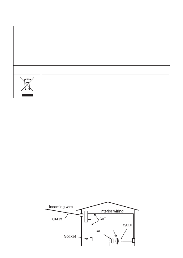
Symbols
Transformer
CAT.III
#
○ Measurement (over-voltage) category
To ensure safe operation of measuring instruments, IEC 61010
establishes safety standards for various electrical environments,
categorized as CAT.I to CAT.IV, and called measurement categories.
Higher-numbered categories correspond to electrical environments
wi th gre ater m oment ary ene rgy, so a mea surin g in strum en t
designed for CAT.III environments can endure greater momentary
energy than one designed for CAT.II.
CAT.I : Sec ond ary e lec tri cal c irc uit s conn ecte d to an A C
CAT.II : Primary electrical circuits of equipment connected to an
CAT.III : Primary electrical circuits of the equipment connected
CAT.IV : The circuit from the service drop to the service entrance,
Primary electrical circuits of the equipment connected
directly to the distribution panel, and feeders from the
distribution panel to outlets.
Instrument with double or reinforced insulation
User must refer to the explanations in the instruction
manual.
(Functional) Earth terminal
Crossed-out wheel bin symbol (according to WEEE
Directive: 2002/96/EC) indicating that this electrical
product may not be treated as household waste, but
that it must be collected and treated separately.
electrical outlet through a transformer or similar device.
AC electrical outlet by a power cord.
directly to the distribution panel, and feeders from the
distribution panel to outlets.
and t o th e po wer m e ter a n d pr ima r y ov erc u rre n t
protection device (distribution panel).
3
Page 6

2. Features
KEW4300 is a simplified earth resistance tester (based on 2-pole
method) that can be used for various distribution lines and electrical
appliances and it also can measure AC/DC voltages. (As for AC
voltages, true rms values can be obtained.)
● Designed to meet the following safety standards
IEC 61010-1 CAT.III 300V, Pollution degree 2
IEC 61010-031
IEC 61557-1, 5
● 200/ 2000Ω (2 ranges) : auto-ranging
● Warning buzzer triggered at 100Ω or less
● LED lights up when a large earth voltage is detected.
● Small test current (max 2mA) not triggering ELB
● Live circuit warning when 30V or higher voltage is detected.
(KEW4300 detects voltage even when measuring resistances.)
● LED light for illuminating measurement points
(It turns on/off automatically in relation to the ambient brightness.)
● Backlight working in conjunction with the LED light
● Glow in the dark button
● User-friendly and compact design
● Auto-p ower-off function is als o availa ble to power off the
instrument when 10 mi n p as s a fter the last operation. This
function does not work while a co ntinuous measur em en t is
performed.
● Strap for prevent drop
● User replaceable metal tips are supplied as standard accessories
4
Page 7
3. Specification
● Measurement range and accuracy (23ºC±5Cº, relative humidity
75% or less)
Voltage/ Earth voltage measurement
Measurement range Display range Accuracy
AC5.0 to 300.0V
(45 to 65Hz)
(425V peak or less)
DC±5.0 to ±300.0V 0.0 to ±314.9V ±1%rdg±8dgt
*AC measurement method : rms detection
* AC/DC auto-detection at 5V or higher
* DC sign appears at 5V or higher.
(H+S(C+P) terminal: positive side, E terminal : negative side)
* The LCD reads 0.0V for 0.9V or lower voltages.
Earth resistance measurement
Range
Measurement
(auto-ranging)
200Ω Range
2000Ω Range 160 to 2099Ω
5.0 to 2000Ω
Measurement method: Constant current inverter
approx. 1.4mA (200Ω Range)/825Hz
approx. 0.7mA (2000Ω Range)/825Hz
0.0 to 314.9V ±1%rdg±4dgt
For the waveforms other than sinewave
of CF<2.5, the specified accuracy
±1%f.s. should be applied.
range
Display range Accuracy
0.0 to 209.9Ω
±3%rdg±5dgt
Open voltage: Approx. 13V
5
Page 8

● Applicable
standards
● IEC 61010-1
● IEC 60529(IP40)
● IEC 61557-1, -5
● IEC 61326-1, 2-2
● IEC 61010-031
MODEL7248 / CAT.III600V
(Alligator clip should be attached and used
in the CAT. III or higher environment.)
MODEL8253 / CAT.III300V
(while it is connected to the instrument)
* When the test leads are connected to the
instrum ent, the l ower cate gory eith er of
them belongs to is applied.
● Location for use Altitude 2000m or less, indoor use
● LCD Segment display with backlight
● Operating
temperature and
-10ºC to 50ºC,
80% or less (no condensation)
humidity range
● Storage
temperature and
-20ºC to 60ºC,
75% or less (no condensation)
humidity range
● Withstand
voltage
● Insulation
resistance
● Auto-power-off
function
AC3,540V(50/60Hz)/ for 5 sec between the
electrical circuit and the enclosure
50MΩ or m o re/ DC1 0 0 0V b e tween th e
electrical circuit and the enclosure
Auto-power-off function operates with audible
warning and powers off the instrument when
approx 10min pass after the last operation.
(This function is disabled during a resistance
measurement.)
● Backlight Turns off auto matic ally when approx 2min
pass after the last operation. (This function is
disabled during a measurement.)
● Dimensions 232(L) x 51(W) x 42(D)mm
(including the metal tip)
● Weight Approx. 220g (including batteries)
● Power source Size AA, alkaline battery x 2pcs
(The use of alkaline LR6 is recommended.)
6
Page 9

● Operating Error
Operating error (B) is an error obtained within the rated operating
conditions, and calculated with the intrinsic error (A), which is an
error of the instrument used, and the error (Ei) due to variations.
According to IEC61557, the maximum operating error should be
within ±30%.
● Operating error at earth resistance measurements (IEC61557-5)
2
2
Formula: B= ±(|A|+1.15 x √E
2
+E
2
+E
)
3
4
A Reference condition
E
E
E
Normal operating position ±90º
1
Variation due to changing the supply voltage (until the
2
Battery symbol
Variation due to changing the temperature
3
appears)
(-10ºC to 50ºC)
E
Variation due to series interference voltage
4
16•2/3Hz, 50Hz, 60Hz, DC: 10V
400Hz: 3V
E
Variation due to resistance of the probes and auxiliary
5
earth electrode resistance
: It is not applicable to digital testers.
E
1
E
: It is not applicable to simplified earth testers.
5
Measurement range within which the maximum operating error
±30% applies: 5.00Ω to 2000Ω.
● Number of measurement
(measuring for 5 sec and take a pause for 25 sec)
Function Resisto r
for test
Number of measurement
(within effective battery voltage
range)
Earth measurement 10Ω Approx. 3000 times
7
Page 10

4. Instrument layout
5 6
3
4
7
2
1
8
(1) Instrument Body
Name Details
H+S(C+P) terminal
1
2 LED light
3
Ambient light sensor
4 Test button
5 Warning LED
6 LCD
7 Power button
8 E terminal
To connect the replaceable metal tip MODEL8072
has been installed and delivered.
To illuminate the measurement spots
The light turns on/off automatically in relation to
ambient brightness.
To sense ambient brightness for turning on/ off
the light
To conduct resistance measurement
Measurement is conducted when the button is held
down.
To give warnings for live circuit (blinking red)
and for large earth voltage (blinking yellow)
LCD with backlight
The backlight turns on/off automatically in relation
to ambient brightness.
To power on/ off the instrument.
The button should be held down for 1 sec or longer.
To connect the test lead MODEL7248
Fig. 4-1
8
Page 11

(2) LCD
Fig. 4-2
● Symbols displayed on the LCD
Indicate the batteries need to replace.
Show the measured results.
Appear when the measured result exceeds the display
range.
Resistance : >2099Ω
Voltage :
> 314.9V (“-OL” for negative DC voltages)
In d ica te the e nd of a m eas ure ment w ith f roz en
measured result.
Blink to give a warning for live circuit
● Symbol displayed at earth measurements
A unit of earth resistance
● Symbols at voltage/ earth voltage measurements
“AC” for alternate voltages and “DC” for direct voltages
・
A unit of voltage
Polarity sign for negative voltages
9
Page 12

5. Accessories
● Test leads
(1) MODEL7248 – with Alligator clip and Flat test bar
(2) Banana plug, both ends, black
L-shaped
Bananaplug
(3) Alligator clip (4) Flat test bar
+
+
Fig.5-2
● Tip metal tips for H+S(C+P) terminal
(1) MODEL8072
Fig. 5-4
Standard metal tip
installed at a shipment.
(2) MODEL8253 (3) MODEL8017
Fig. 5-5 Fig. 5-6
Fig. 5-1
Fig. 5-3
Metal tip with plastic molded
● Others
(1) Carrying case
(2) Strap
(3) Size AA alkaline battery x 2 pcs
(4) Instruction manual
10
Long type and helpful to access
the distant measurement spot
Page 13

6. Getting started
6-1 Battery voltage check
(1) Please refer to “10. Replacing batteries” in this manual and
insert batteries in KEW4300.
(2) Hold down the Power button at least 1 sec and power on
KEW4300.
* A long press of 1 sec or longer is required to power on/ off the
instrument. It is to prevent a malfunction.
(3)
The battery voltage is extremely low when the “ “ symbol
appears at the upper left corner on the LCD. Replace the
batteries with reference to “10. Replacing batteries” to carry out
further measurements.
The use of size AA alkaline battery is recommended. The Battery
symbol may not appear correctly when the other types of batteries
are used.
6-2 Attaching metal tip/ adapter
The metal tip for the H+S(C+P) terminal and the adapters for
MODEL7248 to be connected to the E terminal are replaceable
depending on applications.
DANGER
Always attach and use the M-8253 and the Alligator clip to use
this instrument in the CAT.III or higher environments. The other
metal tips: M-8072, M-8017 and the Flat test bar have a large
exposed metal and may short the equipment under test. It may
cause a malfunction of the equipment under test, a fire or fatal/
serious injuries to the user or the people around.
(1) Replaceable metal tip
The metal tips are replaceable depending on applications.
[Available tip metal tips]
1. MODEL8072 : Standard metal tip installed at a shipment
2. MODEL8253 : Metal tip with plastic molded
3. MODEL8017 : Long type and helpful to access the distant
#
measurement spot
11
Page 14

[How to replace the parts]
メネジ
六角穴
先端金具
Internal
thread
Hexagon
hole
Metal tip
MODEL 8253
MODEL 8072
MODEL 8017
Alligator clip
Flat test bar
Banana plug, both ends
Detach the metal tip by turning the red plastic parts counter
clockwise.
Install the metal tip you want to use into the hexagon hole, and
turn the red plastic parts clockwise to tighten firmly.
Fig. 6-1
(2) Test leads
Either of the following adapters should be connected to the cord
with Banana plug, both ends.
[Adapters for MODEL7248]
1. Alligator clip
2. Flat test bar
[How to connect]
Firmly insert and connect the adapter to the end of the cord with
Banana plug, both ends.
Fig. 6-2
To avoid getting electrical shocks, ensure that test leads are
disconnected from the instrument when replacing the metal tip or
adapter for test leads.
DANGER
#
12
Page 15

7. Voltage measurement
Caution
Do not press
the Test button.
DANGER
#
● Never apply voltages exceeding 300V, max over-voltage
protection, to this instrument.
7-1 Measurement procedure
(1) Connect the test leads to the instrument.
Plug t he L-shaped Banan a plug of MODE L7248 into the E
terminal as illustrated below.
Fig. 7-1
(2) Connect the adapter for test leads to the earth side of the circuit
under test and the metal tip (H+S(C+P) terminal) to the line side
respectively. Connecting that in reverse is also fine if the circuit
under test is not earthed.
13
Fig. 7-2
Page 16

(3) The measured voltage is displayed on the LCD.
LED starts blinking. (Red)
Tak e the read ing wi t hou t pr ess ing th e Tes t bu tto n . The
instrument judges DC or AC and shows “DC” or “AC” sign on the
LCD.
* When negative DC voltages are detected at the H+S(C+P)
terminal, the negative polarity sign “-“ appears to the left of the
measured value.
* Th e LCD d oes not s how “DC ”, “A C” nor s ign when t he
measured values are less than 5V.
The LCD shows “>314.9V” when the measured value exceeds
the display range (over range) and it shows “-OL” for negative DC
voltages.
7-2 Live circuit warning
The warning LED starts blinking red with audible warning when the
measured value is 30V or higher.
Fig.7-3
* The instrument does not carry out resistance measurements
even the Test button is held down while the live circuit warning is
activating.
14
Page 17

8. Earth resistance measurement
H+S(C+P)
terminal
E
terminal
Voltmeter
Earthingsystem
undertest
Earthelectrode
Constantcurrent
generator
Secondary
Primary
I→
This instrument can measure the earth resistances of distribution
line, internal wiring and electrical appliance.
DANGER
● Never apply inputs exceeding 300V between the measuring
terminals at earth voltage measurements.
● No voltage should be applied between the measuring terminals
during earth resistance measurements.
8-1 Principle of measurement
This instrument carries out earth resistance measurements based
on the fall-of-potential method. This is a simplified earth resistance
tester and uses the existing earth systems (with a sufficiently
low earth resistance) such as buried metal pipes like main water
pipe, common earth for commercial power supply and a lightning
electrode on buildings and performs measurements based on the
2-pole measurement method.
The AC constant current
“I” is applied between the
measurement object “Rx”
(earth electrode) and the
existing electrode “re” to
obtain the earth resistance
value “Rx + re” and find out
the voltage “V” between the
E and H+S(C+P) terminals.
See Fig. 8-1.
Rx + re = V / I
The resistance “re” of the ex isting earth electr ode wi th which
H+S(C+P) terminal is connected is added to the true resistance
“Rx” of the measured object, and displayed as the measured result.
Re (measured value) = Rx + re
If the value of “re” is already known, deduct it from the measured
value “Re” to determine “Rx” value.
Rx (true resistance value) = Re – re
#
Fig.8-1
15
Page 18

8-2 Measurement procedure
H+S(C+P)
E
Rx
re
POWER
LOAD
L
N
E
(1) Connect the test leads to the instrument.
Plug the L-shaped Banana plug of MODEL7248 into the E
terminal as illustrated below.
Fig.8-2
(2) Connection
Connect the instrument as illustrated below.
Fig.8-3Measuring the earth resistance
ofload
DANGER
#
Fig.8-4Measu r i n g t h e e a r th
resistanceofwallsocket
● Always use a voltage detector for testing the earth side of the
commercial power supply.
● Do not use this instrument for testing the earth side of the
commercial power supply. It is dangerous because the LCD
may not show the measured voltage even the circuit under
test is in live if the earth of the electrode under test is loose/
disconnected or the connection of the test leads is not proper.
(3) Checking the earth voltage
Check the earth voltage displayed on the LCD without pressing
the Test button.
16
Page 19

● The displayed value should be less than 10V.
LED starts blinking.
10V or higher: yellow
30V or higher: red
The warning LED starts blinking yellow when the earth voltage
is 10V or higher. (The LED starts blinking at 3V or higher if the
frequency of the earth voltage is 400Hz.)
Fig.8-5
Ensue that the systems connected to the earth electrode under
test are turned off to get the earth voltages lower when the
warning LED for earth voltage starts blinking. Otherwise, accurate
measured results can not be obtained. The warning LED for earth
voltage may not light up if the frequency is over 400Hz.
● The warning LED starts blinking red with audible warning when
the voltage of 30V or higher is detected. Earth resis tance
measurements can not be carried out by pressing the Test
button while the live circuit warning is activating.
(4) Measurement
Press the Test button. The LCD shows the measured result.
The instrument carries out an earth resistance measurement
while the Test button is held down. The buzzer sounds when the
measured value is less than 100Ω.
The measurement is halted when the Test button is released,
and the measured data freezes on the LCD. (The “
” symbol
appears on the LCD.) A short press of the Test button while the
result is being displayed on the LCD gets the instrument entered
into the Voltage measurement mode.
● The LCD shows “>2099Ω” when the measured result exceeds
the display range. (Over range)
● The in s t r ument autom a t i c a l ly e n t e r s into th e vo ltage
measurement m ode when sensing the live ci rcuit du ring a
resistance measurement and activates the warning function.
● If an earth resistance measurement is continued at low battery
level with Battery symbol on the LCD, the instrument may be
powered off suddenly.
17
Page 20

9. LCD backlight and LED light
Ambient light sensor
Buzzer sounds
when powering on
the instrument.
Pi・・・
The LCD backlight and the LED light on this instrument turn on/off
automatically in relation to ambient brightness. These lights keep
on for about 15 sec once they turn on. The Ambient light sensor as
shown in the below figure senses the ambient brightness.
Fig.9-1
● Dirt on the surface of the sensor may interfere the proper
operation of the lights. Keep the sensor clean.
● The sensitivity of the sensor is not adjustable. Cover the sensor
with your hand or finger if you need to turn on the lights. The
lights keep on for about 15 sec once they turn on.
[Turning off the Auto-light mode]
The following procedure is for setting the lights always off.
1. Ensure that the instrument is powered off.
2. Hold down the Power button for 1 sec while the Test button is
held down and power on the instrument.
3. Now the Auto-light mode is disabled. Repeating above steps
1.& 2. restores the mode.
The number of beep when powering on the
instrument is different depending on the
selected light mode. The selected mode
will not be reset even after powering off the
instrument.
Number of beep Light mode
Once Auto
Twice Always off
18
Fig.9-2
Page 21

10. Replacing batteries
When the Battery symbol appears on the LCD, replace the batteries
with new ones.
DANGER
Never open the Battery compartment cover if the instrument is wet.
●
● Do not attempt to replace batteries during a measurement.
In order to avoid getting an electrical shock, ensure that the
instrument is powered off and the test leads are disconnected
from the instrument before replacing the batteries.
Always install the Battery compartment cover when starting a
●
measurement. Otherwise, it may cause an electrical shock hazard.
● Do not mix new and old batteries or mix different types of
batteries.
● Install batteries in correct polarity as marked inside.
(1) Power off the instrument and disconnect the test leads from the
instrument.
(2) Loosen the screw at the backside of the instrument and remove
the Battery compartment cover.
(3) Remove all the old batteries. Install two new batteries in correct
polarity.
The use of two, size AA alkaline batteries or alkaline batteries
(LR6) is recommended.
(4) Install the Battery compartment cover and tighten the screw.
#
CAUTION
#
Fig.10-1
19
Page 22

MEMO
20
Page 23

MEMO
21
Page 24

DISTRIBUTOR
Kyoritsu reserves the rights to change specifications or designs
described in this manual without notice and without obligations.
11-04 92-2081
 Loading...