

Page 1
INSTRUCTION MANUAL
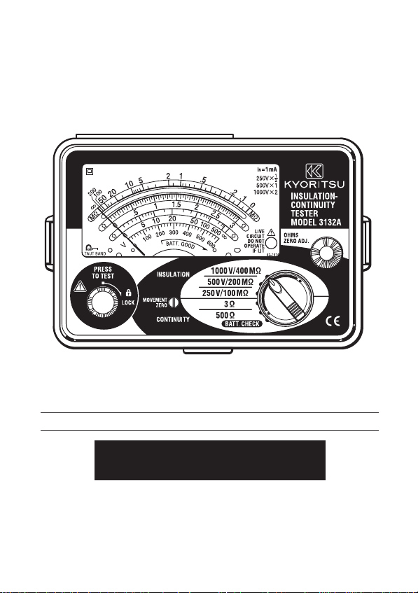
ANALOGUE INSULATION-CONTINUITY TESTER
MODEL 3132A
KYORITSU ELECTRICAL INSTRUMENTS
WORKS, LTD.
Page 2

CONTENTS
1.Safety Precautions ……………………………………………………………1
2.Features ……………………………………………………………………… 4
3.Specifications ………………………………………………………………… 5
4.Instrument Layout …………………………………………………………… 8
5.Preparation for Testing ……………………………………………………… 9
5-1 Mechanical Zero Adjustment …………………………………………… 9
5-2 Battery Voltage Check ………………………………………………… 9
5-3 Test Probe Connection ………………………………………………… 9
5-4Test Probe check ………………………………………………………… 9
6.Operation …………………………………………………………………… 10
6-1 AC Voltage Warning Function ………………………………………… 10
6-2 Insulation Resistance Measurement ………………………………… 11
6-3 Continuity Testing (Resistance Tests) ……………………………… 13
7.Battery & Fuse Replacement ……………………………………………… 15
7-1 Battery Replacement ………………………………………………… 15
7-2 Fuse Replacement …………………………………………………… 15
8.Notes on Accessories ……………………………………………………… 16
8-1 Case Lid ………………………………………………………………… 16
8-2 How to Fit Strap Belt & Test Probe Pouch ………………………… 16
9. Cleaning of the Instrument ………………………………………………… 17
10. Service ……………………………………………………………………… 17
Page 3

1. SAFTY PRECAUTIONS
○ The instrument is designed and tested in accordance with the following
standards and supplied in the best condition.
IEC 61010-1 Overvoltage CAT.III 600V Pollution Degree 2
IEC 61010-2-31 Safety requirements for hand-held probe assemblies
IEC 61557-1/2/4 Measuring equipment for low voltage distribution systems
IEC 61326-1 EMC
IEC 60529 (IP54) Dust & drip proof
This instruction manual contains warnings and safety rules which must be
observed by the user to ensure safety operation of the instrument and to retain
it in safe condition. Therefore, read through these instructions before using the
instrument.
WARNING
Read through and understand instructions contained in this manual
●
before using the instrument.
Save and keep the manual handy to enable quick reference whenever
●
necessary.
The instrument must only be used by a competent trained person and
●
operated in strict accordance with the instructions. KYORITSU will not
accept any liability for any damage or injury caused by misuse or noncompliance with the instructions or safety procedures.
It is essential to understand the safety rules contained in the manual.
●
They must be observed when using the instrument.
Be sure to observe the above rules strictly. Not following the
instructions may cause injury or instrument damage.
The symbol on the instrument means that the user must refer to the
○
relevant section of this manual for safe operation of the instrument.
There are three kinds of the symbol . Read the instructions following
each symbol carefully.
―1―
Page 4

DANGER is reserved for conditions and actions that are likely to cause
serious or fatal injury.
WARNING is reserved for conditions and actions that can cause
serious or fatal injury.
CAUTION is reserved for conditions and actions that can cause minor
injury or instrument damage.
DANGER
Do not use this instrument on energized (LIVE) circuits.
●
Do not make measurement in the presence of flammable gasses.
●
Otherwise, the use of the instrument may cause sparkling, which leads
to an explosion.
Always keep your fingers behind the barrier on test probe during
●
measurement.
Never use the instrument if its surface or your hand is wet.
●
Never open the battery compartment cover while making measurement.
●
WARNING
Do not attempt to take any measurements, if any abnormal conditions
●
are noted, such as broken test probe and cracked enclosure of the
instrument.
Never change ranges with test probe connected to the equipment under
●
test.
Do not install substitute parts or perform any unauthorized modification
●
of the instrument. Return the instrument to Kyoritsu or your distributor
for service and repair to ensure the safety features are maintained.
Do not replace batteries when the surface of the instrument is wet.
●
Make sure to disconnect the test probe from the instrument before
●
opening the battery compartment cover for battery replacement.
―2―
Page 5

CAUTION
Always make sure to set the range switch to the appropriate position
●
before making measurements.
Do not expose the instrument to the direct sun, dew fall or extreme
●
temperature and humidity.
When the instrument will not be in use for a long period of time, place it
●
in storage after removing batteries.
Use a damp cloth soaked in water or neutral detergent for cleaning the
●
instrument. Do not use abrasives or solvents.
―3―
Page 6

2.Features
MODEL-3132A is an analogue tester with five ranges for insulation resistance
measurement and continuity testing (resistance tests) of low voltage
installations.
● Designed to safety standards:
IEC 61557-1 (General requirements for measuring equipment for low
voltage distribution systems)
IEC 61557-2 (Equipment for insulation resistance measurement for low
voltage distribution systems)
IEC 61557-4 (Equipment for resistance tests for low voltage distribution
systems)
● Dust and drip proof construction to IP54.
● Three insulation test ranges : 250V/100MΩ,500V/200MΩ,1000V/400MΩ.
● Two continuity test ranges : 3Ω,500Ω
● AC voltage warning measurement can be made on all ranges without
depressing the test button.
● Easy for battery check.
● When the test button is released any charge stored in the circuit under test
is automatically discharged.
● Remaining electric charges can be observed on AC voltage warning range.
● LIVE circuit audible and visual indication.
● Fuse protected.
● Color coded scales and range switch position for easy reading.
● Uses only 6 x 1.5V battery type R6P,1.5V AA or equivalent.
―4―
Page 7

3.Specifications
● Measuring Range and Accuracy (at 23±5°C, relative humidity 45-75%)
○ Insulation Resistance Ranges:(IEC 61557-2)
Normal output
Voltage
Measuring Ranges 0 - 100MΩ 0 - 200MΩ 0 - 400MΩ
Open -Circuit
Voltage
Normal current 1mA DC +20%, -0%
Short -Circuit
Current
Accuracy guaranteed
range
Accuracy
○ Continuity Test (Resistance Test) Ranges:(IEC 61557-4)
Ranges 3 Ω 500Ω
Open -Circuit Voltage About 4.1V DC
Measuring Current Greater than 200mA
Accuracy ±1.5% of scale length at other measuring ranges
Operating Error
Insulation Resistance Ranges(IEC 61557-2)
Ranges
250V/100MΩ 0.1MΩ - 10MΩ
500V/200MΩ 0.2MΩ - 20MΩ ±30%
1000V/400MΩ 0.4MΩ - 40MΩ
Measuring range to keep Maximum percentage
250V 500V 1000V
Rated test voltage +20%, -0%
About 1.3mA DC
0.1-10MΩ 0.2-20MΩ 0.4-40MΩ
±5% rdg at Accuracy guaranteed ranges
±0.7% of scale length at ranges other than above ranges
operating error operating error
―5―
Page 8

Continuity Test (Resistance Test) Ranges(IEC 61557-4)
Ranges Measuring range to keep Maximum percentage
operating error operating error
3 Ω 0.2Ω - 3Ω ±30%
The influencing variations used for calculating the operating error are denoted
as follows:
Temperature : 0。C and 35。C
Supply voltage : 6.4V to 10.4V
Position : Reference position ±90
※Priortomeasurement,apply0-Adjustmentateachposition.
○ AC Voltage Warning:
Warning range 0-600V
Accuracy ±5% of scale length
Input impedance 1.2MΩ
● Typical Number of measurements (central tendency for supply voltage up to
6.0V)
Insulation Resistance Ranges:
1MΩ at 1000V Range Approx. 1,400 times min.
0.5MΩ at 500V Range Approx. 3,500 times min.
0.25MΩ at 250V Range Approx. 5,500 times min.
Continuity Test (Resistance Test) Ranges:
1Ω at 3Ω Range Approx. 1,500 times min.
● Applicable Standards
IEC 61010-1 Overvoltage CAT.III 600V Pollution Degree 2
IEC 61010-2-31 Safety requirements for hand-held probe assemblies
IEC 61557-1/2/4 Measuring equipment for low voltage distribution systems
IEC 61326-1 EMC
IEC 60529 (IP54) Dust & drip proof
。
● Operating Temperature & Humidity:
0 - 40°C, relative humidity up to 85%
―6―
Page 9

● Storage Temperature & Humidity:
-10 - 50°C, relative humidity up to 75%
● Insulation Resistance :
More than 50MΩ at 1000V DC between electrical circuit
and housing case
● Withstand Voltage: 5550V AC for one minute between electrical circuit and
housing case
● Overload Protection Insulation resistance ranges:
1000V Range 1200V (DC+AC p-p) for 10 seconds
500V Range 600V (DC+AC p-p) for 10 seconds
250V Range 300V (DC+AC p-p) for 10 seconds
Continuity ranges:
3Ω/500Ω Range280V (DC+AC p-p) for 10 seconds
AC Voltage Warning:
1200V (DC+AC p-p) for 10 seconds
● Dimensions: 106(L) x 160(W) x 72(D) mm approx.
● Weight: 560g approx. (including batteries)
● Power Source: 6 x 1.5V battery type R6P ,1.5V AA or equivalent
● Accessories Test Probe MODEL7122 x 1 set
Pouch for test Probe x 1
Shoulder strap x 1
R6P batteries x 6
Spare fuse F500mA/600V x 1
Instruction manual x 1
―7―
Page 10

4.Instrument Layout
① ⑦②
③ ④
⑥
⑨⑧
⑩
⑪
⑫
⑤
①METER MOVEMENT ZERO ADJUST ②TEST BUTTON
③SCALE PLATE ④INPUT CONNECTOR
⑤LIVE CIRCUIT LAMP ⑥OHMS ZERO ADJUST
⑦RANGE SELECTOR SWITCH ⑧
⑨
TEST PROBE (BLACK) EARTH PROBE
⑪TEST PROBE CAP(BLACK) ⑫ALLIGATOR CLIP(BLACK)
TEST PROBE (RED) LINE PROBE
⑩TEST PROBE CAP(RED)
―8―
Page 11

5.Preparation for Testing
5-1 Mechanical Zero Adjustment
Check that the pointer lines up with the middle of the mark on the scale correctly.
If not, adjust it by rotating the meter movement zero adjust with a screwdriver, etc.
5-2 Battery Voltage Check
Set the range selector switch to BATT. CHECK position.
①
② Press the test button.
③ Then the pointer deflects. Judge the battery status with BATT.GOOD
mark on the scale plate.
If the pointer does not move to BATT.GOOD mark, the batteries are
exhausted. Replace them with new batteries according to section 8 for
battery & fuse replacement.
5-3 Test Probe Connection
Insert the test probe fully into the terminal of the instrument.
Connect the earth clip of the test probe (black) to EARTH terminal and the
line probe (red) to LINE terminal of the connector terminal.
5-4 Test Probe Check
Set the range selector switch to 3Ω position and press and turn the Test
button to lock it down.
When the test probe are connected together, the pointer should move from
the ∞ position towards the 0 position on the blue ohms scale. If not, the
probe or fuse may be faulty.
Release the Test button after completion.
WARNING
When the test button is pressed with the range selector switch in the
megaohm range position,take care not to touch the tip of the test probe
where a high voltage is present in order to avoid possible shock hazard.
CAUTION
Do not keep the test button pressed or locked by turning it clockwise
during battery check.
―9―
Page 12

6. Operation
6-1 AC Voltage Warning Function
DANGER
Never make measurements with the battery compartment cover
●
removed.
CAUTION
Never press the test button if the live circuit warning lamp is lit or the
●
warning buzzer sounds. This may damage the circuit.
Voltage check can be made with the range selector switch at any position.
① The presence of AC voltage can be detected. This function operates
automatically when the test button is not depressed, i.e., in the up position.
NOTE:This tester has not been designed to indicate the presence of an
external DC voltage.
② Connect the earth clip of the test probe (black) to the EARTH and the line
probe (red) to the LINE side of the circuit under test.
③ Take the reading on the AC voltage scale.
―10―
Page 13

6-2 Insulation Resistance Measurement
DANGER
Always test the circuit or equipment to ensure it is surely de-energized
●
before measurement according to the instruction of 6-1.
To avoid electrical shock, measurements must be performed on de-
●
energized circuits only.
When the test button is pressed with the range selector switch in the
●
insulation position, take care not to touch the tip of the test probe and the
circuit under test where a high voltage is present in order to avoid possible
shock hazard.
Never make measurement with the battery compartment cover
●
removed.
CAUTION
Never press the test button if the live circuit warning LAMP is lit or the
●
warning buzzer sounds. This may damage the circuit.
Conduct the voltage warning check before measurement to ensure that the
circuit under test is de-energized.
①
Check the voltage which can be applied to the circuit under test and set the
range selector switch to the desired nominal output voltage range.
② Connect the earth clip of the test probe (black) to the earth terminal of the
circuit under test.
③ Put the tip of the line probe (red) to the circuit under test.
―11―
Page 14

④ Check the circuit under test is not energized as follows.
Connect the test probe to the circuit under test and read a voltage value.
If the circuit is live, the meter indicates the voltage, the live circuit lamp is
lit, and warning buzzer sounds.
If the meter indicates 0V, the circuit is dead.
⑤ Press test button. Read the scale directly for the 500V range, multiply by 0.5
for 250V and by 2 for 1000V.
●Continuous Measurement
A lock down feature is incorporated on the test button. Pressing and
turning it clockwise, lock the test button in the continuous operating
position.
To release the lock turn the test button counterclockwise.
Never leave the test button locked down when not is use.
DANGER
Be extremely careful not to get electric shock during insulation resistance
measurement as high voltage is present on the tip of the test probe
continuously.
⑥
With the test probe still connected to the circuit under test after testing,
release the test button to discharge capacitance in the circuit.
●Automatic Circuit Capacitance Discharge Function
This function allows the capacitance stored in the circuit under test to be
automatically discharged after testing.
Discharge can be monitored by the voltage warning range.
DANGER
Do not touch the circuit under test immediately after testing. Capacitance
stored in the circuit may cause electric shock.
Leave the test probe connected to the circuit and never touch the circuit
until the discharge is completed.
●
Output voltage characteristics
The insulation resistance tester must be capable of maintaining the
―12―
Page 15

required test voltage when providing a steady state current of 1mA.
The minimum allowable resistance level is 0.25MΩ for the 250V test,
0.5MΩ for the 500V test and 1MΩ for the 1000V test.
● Principle of Insulation Resistance Measurement
Resistance value can be obtained by applying a
certain high voltage to the resistance
(insulation resistance) and measuring the
flowing current.
Resistance Value = Voltage / Current
RX = V / I
6-3 Continuity Testing (Resistance Tests)
DANGER
Always test the circuit or equipment to ensure it is surely de-energized
●
before measurement according to the instruction of 6-1.
To avoid electrical shock, measurements must be performed on de-
●
energized circuits only.
Never make measurement with the battery compartment cover
●
removed.
―13―
Page 16

CAUTION
Never press the test button if the live circuit warning lamp is lit or the
●
warning buzzer sounds. This may damage the circuit.
In case that an additional operating circuit is connected in parallel to the
●
circuit under measurement, the measurement error might be caused
due to the effects of impedance of the circuit connected in parallel or
transient current.
①
Set the range selector switch to the desired position 3( or 500(.
② Short the line probe (red) and the earth clip of the test probe (black) and
press the test button. Adjust the ohm zero adjust to zero the pointer on
the scale.
③ Connect the test probes to the circuit under test.
④ Check the circuit under test is not energized as follows.
Connect the test probe to the circuit under test and read a voltage value.
If the circuit is live, the meter indicates the voltage, the live circuit lamp is
lit, and warning buzzer sounds. If the meter indicates 0V, the circuit is
dead
⑤Press test button. Read the blue ohm scale directly.
●Continuous Measurement
A lock down feature is incorporated on the test button. Pressing and
turning it clockwise, lock the test button in the continuous operating
position.
To release the lock turn the test button counterclockwise.
Never leave the test button locked down when not is use.
● Principle of Continuity Testing (Resistance Test)
Resistance value can be obtained by applying a
certain current to the resistance under test and
measuring the voltage generated on the both
sides of the resistance under test.
Resistance value = Voltage / Current
RX = V / I
―14―
Page 17

7. Battery & Fuse Replacement
DANGER
Never open the battery compartment cover while making measurement.
●
To avoid possible electrical shock, disconnect the test probe before
opening the cover for battery and fuse replacement.
Replacement fuse must be have the following rating.
●
7-1 Battery Replacement
7-2 Fuse Replacement
Fast acting type, F 500mA/600V, φ6.35×32mm
Disconnect the test probe from the instrument.
①
② Open the battery compartment cover by unscrewing the metal captive
screw to reveal battery compartment. Always replace all six batteries
with new ones at the same time.
Battery type: 6 x 1.5V battery type R6P, 1.5V AA or equivalent
③ Screw the battery compartment lid back on before using the instrument.
①
Disconnect the test probe from the instrument.
② Open the battery compartment cover by unscrewing the metal captive
screw to reveal battery compartment and replace the fuse.
Fuse type: 500mA/600V (F) quick acting ceramic fuse 6.35 x 32mm
③ Screw the battery compartment lid back on before using the instrument.
―15―
CAUTION
Install batteries in correct
polarity as marked inside.
Page 18

8.Notes on Accessories
8-1 Case Lid
The case can be fitted under the housing case as illustrated bellow.
① Open the case lid as shown. ② Turn it 180 degrees.
③ Put the case lid under ④Hook it on the housing case.
the housing case.
8-2 How to fit Neck Strap & Test Probe Pouch
Page 19

9.Cleaning of the Instrument
Cleaning the meter cover
◎
This tester is managed by our company's quality standard and is delivered
in the best condition after passed the inspection. But in the dry time of
winter static electricity sometimes builds up on the meter cover due to the
characteristic of plastic.
When the pointer deflects by touching the surface of this tester or zero
adjustment can not be made, do not try to make measurement.
When static electricity builds up on the meter cover and affects the meter
reading, use a cloth dampened with off-the-shelf anti-statics agent or
detergent to wipe the meter cover surface.
10.Service
If this tester should fail to operate correctly, return it to your nearest
distributors stating the exact nature of the fault.
Before returning the unit, make sure that:
a) Operating instructions have been followed
b) Leads have been inspected
c) Fuse has been checked
d) Battery has been checked
e) The unit is returned with all accessory leads
Remember, the more information written about the fault, the quicker it will be
serviced.
―17――16―
Page 20

DISTRIBUTOR
Kyoritsureserves therightsto changespecificationsor designs
describedinthismanualwithoutnoticeandwithoutobligations.
KYORITSU ELECTRICAL
INSTRUMENTS
WORKS, LTD.
No.5-20,Nakane 2-chome, Meguro-ku, Tokyo
152-0031 Japan
Phone :(03) 3723-0131 Fax : (03) 3723-0152
URL : http://www.kew-ltd.co.jp
E-mail : info@kew-ltd.co.jp
Factories : Uwajima & Ehime
92-1493A 03-08
 Loading...