

Page 1
INSTRUCTION MANUAL
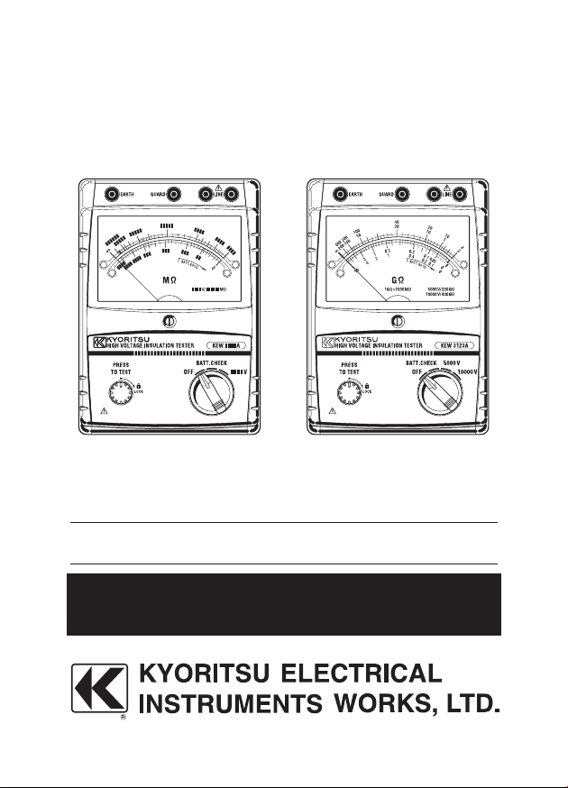
KEW3121A, 3122A KEW3123A
HIGH VOLTAGE INSULATION TESTER
KEW 3121A, 3122A, 3123A
Page 2

CONTENTS
Page
1.Features …………………………………………………………1
2.Specifications ……………………………………………2 〜 3
3.Instrument Layout ………………………………………………4
4.Operating Instructions …………………………………………5
4-1.Mechanical Zero Adjustment ……………………………5
4-2.Battery Check ……………………………………………5
4-3.Insulation Resistance Measurement ……………………6
4-4.Continuous Measurement ………………………………6
4-5.Use of Guard Terminal …………………………………7
5.Battery Replacement ………………………………………8
6.Accessories and options ………………………………………8
6-1. Metal part for Line Probe, and replacement ……………8
6-2. How to use the adaptor for recorder …………………8
7.Cleaning Meter Cover …………………………………………9
Page 3

− 1 −
1. Features
● Battery powered, t he instruments test insulation up to
100000MΩ at 2500V for KEW 3121A, 200000MΩ at 5000V
for KEW 3122A and 200GΩ at 5000V and 400GΩ at 10000V
for KEW 3123A.
● Suited for heavy duty electrical maintenance and servicing of
industrial installations, cables, transformers, generators and
switchgear where high voltage insulation tests are required.
● Dual scale s for l o w an
automatically. Colour coded scales for easy reading plus
LED's that illuminate in matching colour.
● Drip proof construction. The case is sealed with rubber
gaskets to protect internal circuit against rain.
● Hard carrying case furnished as standard accessory. Houses
both instrument and test leads in compact form. Made of
plastic, it is highly water resistant.
● Designe
current consumption is 90mA eight pieces of 1.5V SUM-3(or
equivalent ) permit about 6 hours of continuous operation
even when the instrument is used on maximum load or twice
longer on minimum load.
● Rated output voltage is maintained down to 100MΩ for KEW
3121A, 200MΩ for KEW 3122A and 0.2GΩ/0.4GΩ for KEW
3123A. This permits accurate measurements of
resistance.
d for low power consumption. Since the maximum
d high r a n g e s wh i c h ch a n g e
low insulation
Page 4
− 2 −
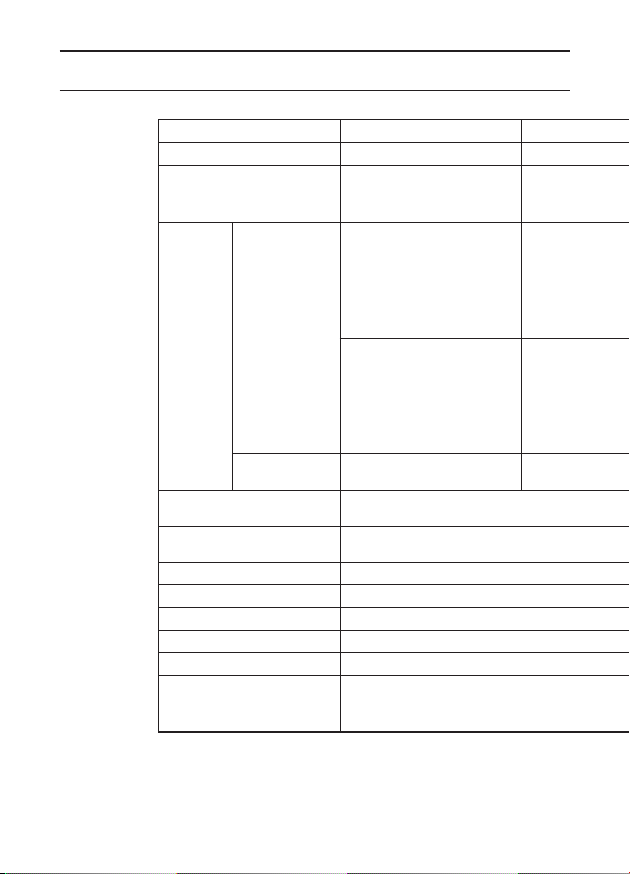
2. Specifications
DC Test Voltage 2500V 5000 V 5000V 10000V
Measuring Ranges
Accuracy
Operating
Temperature & Humidity
Storage
Temperature & Humidity
Insulation Resistance 1000MΩ max./ 1000V between electrical circuit
Withstand Voltage 5000V AC for one minute between electrical circuit & housing case
Dimensions 200(L)×140(W)×80(D)mm
Weight Approx. 1kg(including batteries)
Power Source 8 pcs of R6P (AA) battery or equivalent
Accessories
Insulation
Resistance
Output
Voltage
KEW 3121A KEW 3122A KEW 3123A
0〜2000MΩ/
1000〜100000MΩ
(automatic change)
±5% of reading
(100〜50000MΩ)
±10% of reading
or 0.5% of scale length
( ranges other than
listed above)
23℃ ±5℃
at
±10% of reading
(100〜50000
±20% of reading
or 1.0% of scale length
( ranges other than
listed above)
at −10℃〜+40℃
2500V ±5%
(100〜50000MΩ)
Hard Carrying Case:M-9158 Test Leads
(Line Probe:M-7165A,
Cord:M-7224A, Guard Cord:M-7225A)
MΩ)
0〜5000 MΩ/
2000〜 200000MΩ
(automatic change)
±5% of reading
(200〜 100000MΩ)
±10% of reading
or 0.5% of scale length
( ranges other than
listed above)
at 23℃ ±5℃
±10% of reading
(200〜 100000MΩ)
±20% of reading
or 1.0% of scale length
( ranges other than
listed above)
at −10℃ 〜+40℃
5000V ±5%
(200〜 100000MΩ)
−10℃ 〜+40℃ at 85% max. relative humidity
−20℃ 〜+60℃ at 90% max. relative humidity
Earth
Page 5

− 3 −
0〜5GΩ/2〜200GΩ
(automatic change)
±5% of reading
(0.2〜100GΩ)
±10% of reading
or 0.5% of scale length
( ranges other than
listed above)
at 23℃ ±5℃
±10% of reading
(0.2〜100GΩ)
±20% of reading
or 1.0% of scale length
( ranges other than
listed above)
at −10℃〜+40℃
5000V ±5%
(0.2~100GΩ)
& housing case
Hard Carrying Case:M-9158 Batteries, Test Leads (Line
Probe:M-7165 A, Earth Cord:M-7224A, Guard Cord:M7225A) Pickel type prod:M-8019
(Optional adaptor model 8324 is available for connection to recorder)
0〜10GΩ/4〜400GΩ
(automatic change)
±5% of reading
(0.4〜200GΩ)
±10% of reading
or 0.5% of scale length
( ranges other than
listed above)
at 23℃ ±5℃
±10% of reading
(0.4〜200GΩ)
±20% of reading
or 1.0% of
scale length
( ranges other than
listed above)
at −10℃〜+40℃
10000V ±5%
(0.4~200GΩ)
Page 6

− 4 −
④
⑤
③
②
①
④
⑦
⑥
⑧
⑪ ⑩ ⑨
3. Instrument Layout
① Line Terminal
② Guard Terminal
③ Earth Terminal
④ LE D's fo r H igh & Lo w
Range Indication
⑤ Press to Test Button
⑥ Function Switch
⑦ Me ter Move men t Zero
Adjust
⑧ Bat tery Compa r t ment
Cover
⑨ Line Probe (Red)
⑩ Earth Cord (Black)
⑪ Guard Cord (Green)
Fig.1
Page 7

− 5 −
4. Operating Instructions
CAUTION:
BE CAREFUL ABOUT HIGH VOLTAGE PRESENT ACROSS LINE
AND EARTH TERMINALS OF INSTRUMENT WHEN PRESS TO
TEST BUTTON IS OPERATED. MAKE SURE TO EARTH CIRCUIT
UNDER TEST. ALWAYS CONNECT EARTH TERMINAL OF
INSTRUMENT TO EARTH. THE BUZZER WILL KEEP SOUNDING
DURING INSULATION RESISTANCE MEASUREMENT.
4-1. Mechanical Zero Adjustment
With the function switch set at OFF position, adjust the meter
pointer to
zero adjust screw located at the center of the front panel.
4-2. Battery Check
With the function switch set at BATT. CHECK position, operate the
press to test button. The batteries are good when the pointer stays
in BATT. GOOD area or to the right of this area. If not, replace them.
Note: Refrain from holding down or locking the press to
∞ mark on the scale. Use a screwdriver to turn the
test butt
co nsum ption l arg er than in sul atio n resi stance
measurement while the batteries are still new.
on during this test as it will result in current
Page 8

− 6 −
4-3. Insulation Resistance Measurement
With the function switch set at OFF position, always connect the
circuit under test to earth. Attach the test lead to the earth terminal
of the instrument and connect to the earthed side of the circuit
under test. With the function switch set at 2500V and 5000V for
KEW 3121A and 3122A or 5000V or 10000V for KEW 3123A,
place the line probe in contact with the c
ircuit under test and
operate the press to test button. When the green LED illuminates,
read insulation resistance on the outer scale (for high range). Use
the inner scale where the red LED illuminates. For insulation testing
at 5000V and 10000V, read the black and red scales respectively
(for KEW 3123A). After a test, release the press to test button and
wait for several seconds without disconnec
ting the line probe from
the circuit tested. This is intended to discharge the charge stored in
the circuit tested.
4-4. Continuous Measurement
Make sure that the circuit under test is earthed and that the test
lead attached to the earth terminal of the instrument is connected
to the earthed side of the circuit under test. Push the press to test
button and turn clockwise to lock for continuous measu
rement.
When making this measurement, good care must be taken against
the high voltage continuously present across the line and earth
terminals of the instrument.
Note: Make certain that the circuit under test does not
include components which will be damaged by the
high voltage applied.
Page 9

− 7 −
4-5. Use of Guard Terminal
When measuring the insulation resistance of a cable, Ieakage
current flowing on the surface of cable jacket and the current
flowing inside the insulator are mixed and may cause error in
insulation resistance value. In order to prevent such error, wind a
conductive wire around the point where leakage current flows. Then
connect it to the Guard terminal as shown in below Fig
.2. This is
to move out the surface leakage resistance of the cable insulation
to measure only the volume resistance of insulator. Make sure to
use the Guard cord supplied with this instrument to connect the
instrument to Guard terminal.
Fig.2
Page 10

− 8 −
5. Batttery Replacement
Remove the battery compartment cover by loosening the screw located
on the back of the housing case. Replace the whole battery pack. Alkaline
batteries are recommended where the instrument is used at a temperature
below the freezing point. The ordinary manganese batteries will deteriorate
below the freezing point.
6. Accessories and options
6-1. Metal part for Line Probe, and replacement
(1)Tip metal parts
MODEL8252: Standard Prod (straight type, with molded parts)
MODEL8254: Straight Type Prod
MODEL8019: Pickel Type Prod (accessory)
To be used to hook the instrument.
Note:Option KEW3121A, KEW3122A
(2)How to replace it
Turn the Line probe counterclockwise to remove the attached tip
tip metal you want to use to the hexagon socket and turn it to clockwise together
with the tip of probe, and tight up screws.
metal. Put the
6-2. How to use the adaptor for recorder
MODEL8324 is the adaptor for recorder for output current measurement. Connect
it as shown in the below Fig.3.
Output is DC10mV when current of 1μA is flowing.
Page 11

− 9 −
To recorder
To shield or Earth
Fig.3
7. Cleaning Meter Cover
This earth tester is managed by our company's quality standard and is
delivered in the best condition after passed the inspection. But in the dry
time of winter static electricity sometimes builds up on the meter cover due
to the characteristic of plastic.
When the pointer deflects by touching the surface of this tester or zero
adjustment can not be made, do not try to make m
When static electricity builds up on the meter cover and affects the meter
reading, use a cloth dampened with off-the-shelf anti-statics agent or
detergent to wipe the meter cover surface.
easurement.
Page 12

DISTRIBUTOR
Kyoritsu reserves the rights to change specific ations o r design s
described in this manual without notice and without obligations.
2-11 92-1919B
 Loading...