

Page 1
INSTRUCTION MANUAL
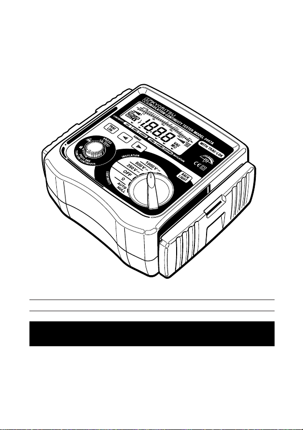
DIGITAL INSULATION-CONTINUITY TESTER
MODEL 3005A /3007A
KYORITSU ELECTRICAL INSTRUMENTS
WORKS, LTD.
Page 2

CONTENTS
1. SAFETY PRECAUTIONS ······································································· 1
2. FEATURES ···························································································· 4
3. SPECIFICATIONS ················································································· 5
4. INSTRUMENT LAYOUT ········································································· 9
4-1 Instrument layout ············································································· 9
4-2 LCD ································································································ 10
4-3 Connector ······················································································· 11
5. PREPARATION FOR MEASUREMENT ··············································· 12
5-1 Removing the Cover ······································································· 12
5-2 Battery Voltage Check ····································································· 12
5-3 Test Probe Connection ··································································· 12
6. OPERATION ·························································································· 13
6-1 Disconnection and Check of Power Source of
the Circuit under Test ····································································· 13
6-2 Insulation Resistance Measurement ··············································· 14
6-3 Continuity Measurement (Resistance Tests) ·································· 16
6-4 Continuous Measurement ······························································· 17
7. FUNCTIONS ·························································································· 18
7-1 TRAC-LOK Mode (Model 3007A only) ············································ 18
7-2 AUTO NULL ···················································································· 18
7-3 Back Light (Model 3007A only)························································ 18
7-4 Auto Power Off ················································································ 18
8. BATTERY & FUSE REPLACEMENT ···················································· 19
8-1 Battery Replacement ······································································ 19
8-2 Fuse Replacement ·········································································· 19
9. CASE AND STRAP BELT ASSEMBLY·················································· 20
10. CLEANING OF THE INSTRUMENT ····················································· 21
11. SERVICING···························································································· 21
Page 3

1. SAFTY PRECAUTIONS
○ The instrument is designed to produce in accordance with the following
standards and supplied in the best conditions after successfully clearing
the inspection.
・IEC 61010-1 Overvoltage CAT III 300V Pollution Degree 2
・IEC 61010-2-31 (Safety requirements for hand-held probe assemblies)
This instruction manual describes warnings and safety rules which must be
observed by the user to ensure safety operation of the instrument and to
retain it in safe condition. Therefore, read through these instructions before
using the instrument.
WARNING
Read through and understand instructions contained in this manual
●
before using the instrument.
Save and keep the manual handy to enable quick reference whenever
●
necessary.
The instrument must only be used by a competent trained person and
●
operated in strict accordance with the instructions. KYORITSU will not
accept any liability for any damage or injury caused by misuse or noncompliance with the instructions or safety procedures.
It is essential to understand the safety rules contained in the manual.
●
They must be observed on using the instrument.
Be sure to observe the above rules strictly. Not following the
instructions may cause injury or instrument damage.
○ The symbol on the instrument means that the user must refer to the
relevant section of this manual for safe operation of the instrument. There
are three kinds of the symbol . Read the following instructions of each
symbol carefully.
― 1 ―
Page 4
DANGER is reserved for conditions and actions that are likely to cause
serious or fatal injury.
WARNING is reserved for conditions and actions that can cause
serious or fatal injury.
CAUTION is reserved for conditions and actions that can cause minor
injury or instrument damage.
DANGER
Do not use this instrument on energized (LIVE) circuits.
●
Do not take measurement in the presence of flammable gasses.
●
Otherwise, the use of the instrument may cause sparkling, which leads
to an explosion.
Always keep your fingers behind the barrier on test probe during
●
measurement.
Never use the instrument if its surface or your hand is wet.
●
Never open the battery compartment cover while taking measurement.
●
WARNING
Do not attempt to take any measurements, if any abnormal conditions
●
occur, such as broken test probe and cracked enclosure of the
instrument.
Never change function switches with test probe connected to the
●
equipment under test.
Do not install substitute parts, perform any unauthorized modification, or
●
disassemble the instrument. Return the instrument to Kyoritsu or your
distributor for service and repair so as to ensure the safety features are
maintained.
Do not replace batteries when the surface of the instrument is wet.
●
Make sure to disconnect the test probe from the instrument before
●
opening the battery compartment cover for battery replacement.
― 2 ―
Page 5

CAUTION
Always make sure to set the function switch or range selector switch to
●
the appropriate position before taking measurements.
Do not expose the instrument to the direct sun, dew fall or extreme
●
temperature and/or humidity.
When the instrument will not be in use for a long period of time, place it
●
in storage after removing batteries.
Use a damp cloth soaked in water or neutral detergent for cleaning the
●
instrument. Do not use abrasives or solvents.
― 3 ―
Page 6

2. FEATURES
MODEL-3005A/3007A are microprocessor controlled insulation-continuity
testers.
● Designed to safety standards:
IEC 61010-1 Overvoltage CAT III 300V Pollution Degree 2
IEC 61010-2-31 (Safety requirements for hand-held probe assemblies)
● Display with back light function to facilitate work at night or dimly lit
locations (Model 3007A only)
● Bar graph to indicate measured results
● Strap belt to make both hands' operation easier
● Live circuit warning indication and buzzer
● Auto discharge function
When insulation resistance is measured, electric charges stored in
capacitive circuits are automatically discharged after testing. Discharge
can be checked with live circuit warning.
● Auto power off function
To prevent the instrument from being left powered on and conserve
battery power, the instrument automatically turns off approx. 10 minutes
after the last switch operation.
● LOK mode (Model 3007A only)
The test current is removed once a stable reading is reached to prevent
unnecessary battery consumption.
― 4 ―
Page 7
3. SPECIFICATIONS
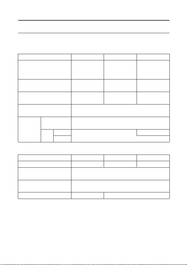
● Measuring Range and Accuracy (at 23±5°C, relative humidity 45 -75%)
○ Insulation Resistance Ranges:
Nominal Output Voltage 250V 500V 1000V
Measuring
Ranges
Open-Circuit 250V DC 500V DC 1000V DC
Voltage +20%,-0% +20%,-0% +20%,-0%
Nominal Current
Short-Circuit
Current
20MΩ
Accuracy
○ Continuity Ranges:
Ranges 20Ω 200Ω 2000Ω
Measuring Ranges 0 ~ 19.99Ω 0 ~ 199.9Ω 0 ~ 1999Ω
Open-Circuit
Voltage
Measuring Current
at 0.2Ω ~ 2Ω
Accuracy
○ AC Voltage Indication
200MΩ
0~1GΩ
2000
MΩ
1G~2GΩ
0 ~ 600V ±5%rdg ±3dgt
0 ~19.99MΩ 0 ~19.99MΩ 0 ~19.99MΩ
0 ~ 199.9MΩ 0 ~ 199.9MΩ 0 ~ 199.9MΩ
0 ~ 1999MΩ 0 ~ 1999MΩ 0 ~ 1999MΩ
1mA DC min. 1mA DC min. 1mA DC min.
at 0.25MΩ at 0.5MΩ at 1MΩ
1.5mA approx
±1.5%rdg ±5dgt
±10%rdg ±3dgt
7 ~ 12V approx
200mA min
±1.5%rdg ±5dgt
±3%rdg ±3dgt
±1.5%rdg ±3dgt
― 5 ―
Page 8
● Typical Number of Measurements.
(central tendency for supply voltage up to 8V)
Insulation Resistance Ranges:
Approx. 1000 times min. at load 0.5MΩ
Continuity Ranges:
Approx. 700 times min. at load 1Ω
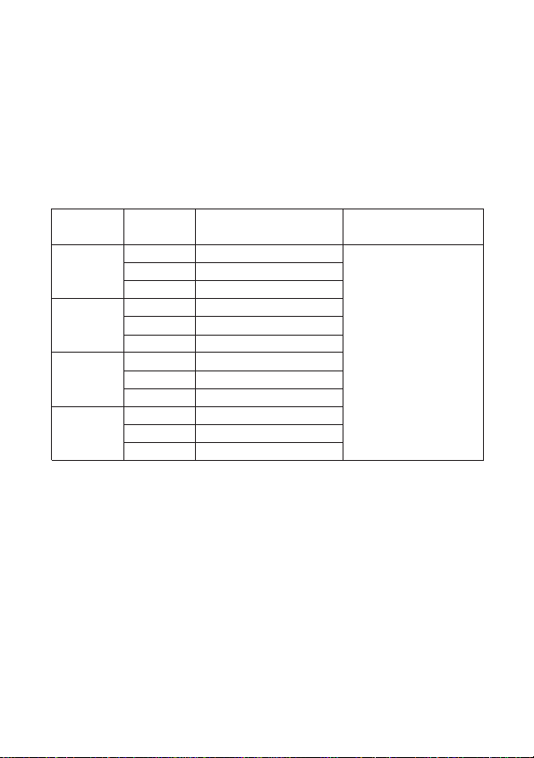
● Operating Errors (IEC 61557-2,-4)
Functions Range
20MΩ 0.50 ~ 19.99MΩ
1000V 200MΩ 1.0 ~ 199.9MΩ
2000MΩ 10 ~ 1000MΩ
20MΩ 0.50 ~ 19.99MΩ
500V 200MΩ 1.0 ~ 199.9MΩ
2000MΩ 10 ~ 100MΩ
20MΩ 0.25 ~ 19.99MΩ ±30%
250V 200MΩ 1.0 ~ 199.9MΩ
2000MΩ 10 ~ 100MΩ
20Ω 0.20 ~ 19.99Ω
Ω 200Ω 1.0 ~ 199.9Ω
2000Ω 10 ~ 1999Ω
The influencing variations used for calculating the operating error are
denoted as follows;
Temperature: 0℃ and 35℃
Supply voltage : 8V to 13.8V
● Applicable Standards
IEC 61010-1 Over voltage CAT III 300V Pollution Degree 2
IEC 61010-2-31 Safety requirements for hand-held probe
IEC 61557-1/2/4 Measuring equipment for low voltage
IEC 61326-1 EMC
Measuring range to keep Maximum percentage
operating error operating error
assemblies
distribution systems
― 6 ―
Page 9

IEC 60529 (IP54) Dust & drip proof
● Operating System: Dual integration
● Display: Liquid crystal display (maximum count: 1999),
Unit, Mark
Bar graph 30 points max. (20 points on Ω
range)
● Over range Indication: "OL" is shown on the display.
● Sample Rate: Approx. 0.5 ~ 2.5 times per second
● Operating Temperature 0 ~ +40
& Humidity:
● Storage Temperature -20 ~ +60
& Humidity:
● Insulation Resistance:
● Withstand Voltage: 3700V AC for one minute between electrical
● Overload Protection
Insulation resistance ranges:
1000V Range 1200V (DC+AC p-p) for 10 seconds
500V Range 600V (DC+AC p-p) for 10 seconds
250V Range 300V (DC+AC p-p) for 10 seconds
Continuity ranges:
20/200/2000Ω 280V (DC+AC p-p) for 10 seconds
Range (Protection by fusing)
°C, relative humidity up to 85%
°C, relative humidity up to 75%
More than 50MΩ at 1000V DC between electrical
circuit and housing case
circuit and housing case
― 7 ―
Page 10

● Dimensions: 185(L) x 167(W) x 89(D) mm approx.
①
②
③
④
⑤
⑥
⑦
⑧ ⑨
⑩
⑪
● Weight: 990g approx. (including batteries)
● Power Source: 8 x R6P, 1.5V AA or equivalent
Auto-power-off Function:
●
● Accessories
Test Probe MODEL7122 x 1 set
Strap belt x 1
Test probe pouch x 1
Batteries (R6P) x 8
Instruction manual x 1
Spare fuse F600V/500mA x 1
Automatically turns off approx. 10 minutes after
the last switch operation.
Consumption current: approx. 75µA
― 8 ―
Page 11

4. INSTRUMENT LAYOUT
①
②
③
④
⑤
⑥
⑦
⑧ ⑨
⑩
⑪
4-1 INSTRUMENT LAYOUT
LCD DISPLAY
①…
②… TRAC-LOKSWITCH (Model 3007A only)
③… RANGE SELECTOR SWITCH
④… TEST BUTTON
⑤… CONNECTOR
⑥… BACK LIGHT SWITCH (Model 3007A only)
⑦… FUNCTION SWITCH
⑧… TEST PROBE (RED)
⑨… TEST PROBE (BLACK)
⑩… ALLIGATOR CLIP (BLACK)
⑪… PLOBE CAP (BLACK & RED)
― 9 ―
Page 12

4-2 LCD DISPLAY
1
812
9
10
11
3
2
4
5
6
7
1… INSULATION RESISTANCE SCALE
2… BAR GRAPH
3… CONTINUITY SCALE
4… LIVE CIRCUIT WARNING
AC LIVE CIRCUIT
WARNING
0〜2V 0〜2V
3〜30V 3〜60V
31〜60V 61〜120V
61〜120V 121〜240V
120V over 240V over
5… TRACK/LOK MODE
6… AUTONULL OPERATION
7… BATTERY VOLTAGE WARNING
8… CONTINUITY/INSULAATION RESISTANCE RANGE SETTING
9… UNIT
DISCHARGE VOLTAGE
― 10 ―
Page 13

10…OUTPUT VOLTAGE GRAPH (INSULATION RESISTANCE)
FUNCTION SETTING
PER RATED OUTPUT VOLTAGE
1 ~ 24%
25 ~ 49%
50 ~ 74%
75 ~ 99%
100% or over
11… OUTPUT VOLTAGE RANGE
12… MEASUREMENT VALUES
4-3 Connector
― 11 ―
Page 14

5. PREPARATION FOR MEASUREMENT
5-1 Removing the Cover
Model 3005A/3007A have a dedicated cover to protect against an impact
from the outside and prevent the operation part, LCD, and connector
socket from becoming dirty. The cover can be detached and put on the
back side of the main body during measurement.
Method of removing the cover Method of storing the cover
5-2 Battery Voltage Check
Set the function switch to any position except "OFF".
①
② When the battery voltage warning symbol ( ) is lit, the batteries are
exhausted. Replace all of them with new ones according to
for battery & fuse replacement.
5-3 Test Probe Connection
Insert test probes fully into connector terminals of the instrument.
Connect test probe (black) to EARTH terminal and test probe (red) to
LINE terminal of connector terminal.
section 8
― 12 ―
Page 15

6. OPERATION
6-1 Disconnection and check of power source of the circuit under test
DANGER
To avoid possible electrical shock, do not perform measurements on
●
energized (LIVE) circuits.
Never make measurements with the battery compartment cover
●
removed.
CAUTION
Never press the test button if the live circuit warning is indicated or the
●
warning buzzer sounds. This may damage the circuit.
Voltage check can be made with the function switch at any position except "OFF".
Be sure to turn off the breaker for the circuit under test.
① Connect the test probe (black) to the earth side and the test probe (red) to
the line side of the circuit under test.
② Ensure that the live circuit warning is not lit and the audible warning is not
present. When the live circuit warning is lit and the buzzer sounds, never
press the test button. Voltage is generated in the circuit under test.
Recheck that the breaker for the circuit under test is "OFF".
― 13 ―
Page 16

6-2 Insulation Resistance Measurement
DANGER
Always test the circuit or equipment to ensure it is surely de-energized
●
before measurement according to the instruction of 6-1.
To avoid electrical shock, measurements must be performed on de-
●
energized circuits only.
When the test button is pressed with the function switch in the MΩ
●
position, take care not to touch the tip of the test probe and the circuit
under test where a high voltage is present in order to avoid possible
shock hazard.
Never make measurement with the battery compartment cover removed.
●
CAUTION
Never press the test button if the live circuit warning is indicated or the
●
warning buzzer sounds. This may damage the circuit.
Conduct the voltage warning check before measurement to ensure that
●
the circuit under test is de-energized.
① Check the voltage which can be applied to the circuit under test and set
the function switch and the range selector switch to the desired range.
② Connect the test probe (black) to the earth terminal of the circuit under
test.
③ Put the tip of the test probe (red) to the circuit under test and press the
test button.
The buzzer sounds intermittently during measurement.
Current outputs from the earth terminal, and returns to the line terminal.
― 14 ―
Page 17

④ Read the resistance value from the LCD.
⑤ With the test probe still connected to the circuit under test, release the test
button to discharge capacitance in the circuit after measurement.
DANGER
Do not touch the circuit under test immediately after testing. Capacitance
stored in the circuit may cause electric shock.
Leave test probes connected to the circuit and never touch the circuit until
the discharge is completed.
●Principle of Insulation Resistance Measurement
Resistance value can be obtained by applying a certain high voltage to the
resistance (insulation resistance) and measuring the flowing current.
Resistance Value = Voltage / Current
RX = V / I
― 15 ―
Page 18

●Terminal connection of insulation resistance test
In case of testing insulation of insulated wire and cable against the earth
at direct current, connecting - pole of power to cable conductor, + to the
earth obtains smaller measuring value, compared with connecting the
other way round. This connecting method is generally acknowledged
relevant to detect defective insulation.
6-3 Continuity Measurement (Resistance Tests)
DANGER
Always test the circuit or equipment to ensure it is surely de-energized
●
before measurement according to the instruction of 6-1.
To avoid electrical shock, measurements must be performed on de-
●
energized circuits only.
Never make measurement with the battery compartment cover
●
removed.
CAUTION
Never press the test button if the live circuit warning is indicated or the
●
warning buzzer sounds. This may damage the circuit.
When an additional circuit is connected in parallel with the circuit under
●
test , inaccurate reading may be taken.
① Set the function switch to the "AUTO NULL" position.
② Short the test probes (red) and (black) and press the test button. Then the
resistance of the test probes is displayed and memorized with
microprocessor.
③ Set the function switch to "Ω" position.
④ Connect the test probes to the circuit under test and press the test button.
⑤ Read the resistance value from the LCD.
NULL symbol ( ) is displayed while AUTO NULL function is working.
●
AUTO NULL will be cancelled when the instrument is powered off.
●
Page 19

● Principle of Continuity Measurement (Resistance Test)
Resistance value can be obtained by applying a certain current to the
resistance under test and measuring the voltage generated on the both
sides of the resistor under test.
Resistance value = Voltage / Current
RX = V / I
6-4 Continuous Measurement
A lock down feature is incorporated on the test button. Pressing and
turning it clockwise, lock the test button in the continuous operating
position.
To release the lock, turn the test button counterclockwise.
NOTE:
Model 3007A has TRAC/LOK function. When "LOK" mode is selected,
sampling is conducted only once, even though the test button is locked
down for continuous measurement.
To make continuous measurement, select "TRAC" mode.
DANGER
Be extremely careful not to get electric shock during insulation resistance
measurement as high voltage is present on the tip of test probes
continuously.
― 17 ―― 16 ―
Page 20

7. FUNCTIONS
7-1 TRAC-LOK MODE (Model 3007A)
TRAC mode
LOK mode :
7-2 AUTO NULL
When conducting continuity tests, the contact resistance of test probes etc.
is automatically subtracted before the real resistance is displayed to obtain
more accurate reading.
This function is invalid when the contact resistance, etc. is 10Ω or more.
・ NULL symbol ( ) is displayed while AUTO NULL function is working.
・ AUTO NULL will be cancelled when the instrument is powered off.
7-3 BACK LIGHT (Model 3007A)
Use BACK LIGHT to facilitate working at night or dimly lit situations.
When the back light switch is pressed with the function switch in any
position except "OFF", the back light continues illuminating for approx. 40
seconds and then turns off automatically.
When the back light switch is pressed again, the BACK LIGHT will turn off
even within the lighting time.
Press the back light switch while it is on, the light gets brighter. Press it
again to turn it OFF.
7-4 AUTO-POWER-OFF
The instrument automatically turns off approx. 10 minutes after the last
switch operation. To return to the normal mode, turn the function switch
off, then to the desired position.
Slight current is still consumed even after the instrument was powered off
by auto-power-off function. Turn the function switch to the "OFF" position
when not using the instrument.
: Measurement can be conducted while the test button is
being pressed.
When making continuous measurement, select this mode.
When the test button is pressed, measurement can be conducted
only once, and output is stopped, then automatically discharged.
This allows to economize on the battery life.
CAUTION
― 18 ―
Page 21

8. BATTERY & FUSE REPLACEMENT
DANGER
Never open the battery compartment cover while making measurement.
●
To avoid possible electrical shock, disconnect the test probe before
opening the cover for battery and fuse replacement.
Replacement fuse must be have the following rating.
●
8-1 Battery Replacement
8-2 Fuse Replacement
Fast acting type, F 500mA/600V, φ6.35×32mm
Disconnect test probes from the instrument.
①
② Open the battery compartment cover by unscrewing the metal captive
screw to reveal battery compartment. Always replace all eight
batteries with new ones at the same time.
Battery type: 8 x R6P, 1.5V AA or equivalent
Disconnect the test probe from the instrument.
①
② Open the battery compartment cover by unscrewing the metal captive
screw to reveal battery compartment and replace the fuse.
Fuse type: 600V/500mA (F) quick acting ceramic fuse 6.35 x 32mm
CAUTION
Install batteries in correct
polarity as marked inside.
― 19 ―
Page 22

9. CASE AND STRAP BELT ASSEMBLY
By hanging the instrument around the neck, both hands can be used freely
for easy and safety working.
Pass the strap belt down through
the side panel of the main body
from the top, and up through the
slots of the probe case from the
bottom.
Pass the strap through the buckle,
adjust the strap for length and
secure.
― 20 ―
Page 23

10. CLEANING OF THE INSTRUMENT
● When cleaning the instrument, wipe it with a silicon cloth or soft cloth to
remove dust or dirt.
● When it is hard to remove the dirt, wipe it with a cloth wet with water and
dry the instrument completely after cleaning.
CAUTION
Never use any solvent which may transmute plastics, for example, organic
solvent such as benzene, acetone, etc.
11. SERVICING
If this tester should fail to operate correctly, return it to your nearest
distributors stating the exact nature of the fault.
Before returning the instrument, make sure that:
a) Operating instructions have been followed.
b) Leads have been inspected.
c) Fuse has been checked.
d) Battery has been checked.
e) The unit is returned with all accessory leads.
Remember, the more information written about the fault, the quicker it will be
serviced.
― 21 ―
Page 24

DISTRIBUTOR
Kyoritsureserves therightsto changespecificationsor designs
describedinthismanualwithoutnoticeandwithoutobligations.
KYORITSU ELECTRICAL
INSTRUMENTS
WORKS, LTD.
No.5-20,Nakane 2-chome, Meguro-ku, Tokyo
152-0031 Japan
Phone :(03) 3723-0131 Fax : (03) 3723-0152
URL : http://www.kew-ltd.co.jp
E-mail : info@kew-ltd.co.jp
Factories : Uwajima & Ehime
01-09 92-1492A
 Loading...