

Page 1
1.Safety warnings
○ This instrument has been designed, manufactured and tested
according to IEC 61010: Safety requirements for Electronic
measuring apparatus, and delivered in the best condition after
passing quality control tests. This instruction manual contains
warnings and safety rules which have to be observed by the
user to ensure safe operation of the instrument and to maintain
it in safe
condition. Therefore, read through these operating
instructions before using the instrument.
# WARNING
● Read through and understand the instructions contained in
this manual before using the instrument.
● Kee p t h e ma n ual at hand to enabl e q u ick refe r e nce
whenever necessary.
● The instrument is to be used only in its intended applications.
● Understand and follow all the safety instructions conta
ined in
the manual.
It is essential that the above instructions are adhered to. Failure
to follow the above instructions may cause injury, instrument
damage and/or damage to equipment under test. Kyoritsu is by
no means liable for any damage resulting from the instrument in
contradiction to these cautionary notes.
○ Th e symbo l # in dic at e d on t he i ns tru men t, m ea ns that
the user must re fer to th e rel
ate d p arts in the ma nual for
safe operati on of the instrument. It is essential to read the
instructions wherever the symbol appears in the manual.
# DANGER : is reserved for conditions and actions that are
likely to cause serious or fatal injury.
# WARNING : is reserved for conditions and actions that can
cause serious or fatal injury.
# CAUTION : is reserved for conditions and actions that can
c
ause injury or instrument damage.
Please refer to following explanation of the symbols used on the
instrument and in this manual.
#
User must refer to th e expl an at io ns in the inst ru ct io n
manual.
Instrument with double or reinforced insulation
Appli ca ti on around haza rd ou s live cond uc to rs is NO T
permitted.
Cr oss e d-o ut whe el bin s ymb o l (ac c ord ing t o WEEE
Directive: 2002/96/EC) indicating that this electrical product
may not be treated as household waste, but that it must be
collected and treated separately.
Instruction Manual
# DANGER
● Ne ve r make mea su re ments on a cir cu it in w hi ch ear th
potentials of 300V or higher exist.
● Do not attempt to make measurements in the presence of
flammable gasses. Otherwise, the use of the instrument may
cause sparking, which can lead to an explosion.
● Never attempt to use the instrument if its surface or your
hand is wet.
● Do no t ex ceed the maxim u m al l o wabl e inp u t of any
measuring ra
nge.
● Ne v e r open the Ba tte r y co mpa r tme n t cove r du rin g a
measurement.
● Never atte mp t t o make an y measure me nt s if the clamp
sensor and/or the instrument has any structural abnormality,
such as a crack, or if the cover is not securely attached.
● Do not measure AC currents.
● Th e inst rum e n t sh o u l d be used on ly in its in ten ded
appli ca ti on s or co nd itions. Othe rw is e, safe ty function s
equipped with the
instrument do not work, and instrument
damage or serious personal injury may be caused.
# WARNING
● Never attempt to make any measurements if any abnormal
conditions, such as a broken cover or exposed metal parts
are present on the instrument and clamp sensor.
● Do not install substitute pa rts or make any modifi cations
to the i ns tru men t. R et urn the i nst ru men t to y our loc al
KYORITSU distributor fo
r repair or re-calibration in case of
suspected faulty operation.
● Do not try to re pl ac e the b at te ri es if t he surface of the
instrument is wet.
● Ensur e t hat th e Clamp senso r is di sc onnecte d from th e
obje ct under test, and that the instrument is powered off
when openin g the Batter y compartment cover for batter y
replacement.
# CAUTION
● Do n ot exp ose the ins tru men t to dir ect su nl i gh t , hig h
temperat
ure, humidity or dew.
● This instrument is not water/ dustproof. Do not use it in a
dusty environment or where it will get wet.
● Always po wer off t he inst rument after us e. Remo ve the
batteries if the instrument is to be stored and will not be in
use for a long period.
● Use a damp cloth with neutral detergent or water for cleaning
the instrument. Do not use abrasives or solvents.
○ Measurement C
ategory
To ensure safe operation of measuring instruments, IEC 61010
establ ishes safety stan dards for various electri cal environ ments, categorized as O to CAT.IV, and called measurement
ca t ego r ies . Hi ghe r -nu m ber e d cate g ori e s corr e spo n d to
electrical environments with greater momentary energy, so a
measuring instrument designed for CAT.III environments can
endure greater momentary energy than
one designed for CAT.II.
O : Circuits which are not directly connected to the mains
power supply.
CAT.II : Electric al circu its of equip ment conn ected to an AC
electrical outlet by a power cord.
CAT.III : Primary electrical circuits of the equipment connected
directly to the distribution panel, and feeders from the
distribution panel to outlets.
CAT.IV : T he ci rcu i t fr o m th e s e r vic e dro p to the s
er v i ce
ent rance, an d to the po w e r me t e r an d p r i m a r y
overcurrent protection device (distribution panel).
2. Feature
● Instrumentation signal (DC4–20mA) measurement
● DC current (0-100mA) measu re ment without brea ki ng the
electrical circuit.
● LED light for illuminating the measurement spot
● Auto-power-off function
● Percentage span
● Analog output function to output the measured results to the
recorde
r or digital multi-meter.
● Data hold function
3.Specification
● Measuring range and accuracy (23ºC±5ºC, RH 75% or less)
(1) DC current (auto-range)
Range Display range
Guaranteed
accuracy
Accuracy Condition
20mA 0.00 to ±21.49mA 0.00 to ±21.49mA ±0.2%rdg±5dgt After Zero-
Adjustment
described at
clause 6 (1)
100mA ±21.0 to ±126.0mA ±21.0 to ±120.0mA ±1.0%rdg±5dgt
(2) Analog output function
To o ut put DC volt ag e (10m V/ mA ) correspo nd in g to the
reading.
Range Display range Output voltage Accuracy
20mA 0.00 to ±21.49mA 0.0 to ±214.9mV Accuracy specified at clause 3
(1) plus (±0.5mV)
100mA ±21.0 to ±126.0mA ±210 to ±1260mV Accuracy specified at clause 3
(1) plus (±3mV)
* 1300mV is output when the display shows OL. (-1300mV for
-OL.)
See clause 6 for explanations on OL display.
* Output impedance : approx. 5kΩ
● Applicable
standards
IEC61010-1, IEC61010-2-
030
Measurement CAT.II 300V Pollution degree 2
IEC61010-2-032
IEC61326 (EMC)
IEC60529 IP40
● Display Liquid crystal display
(see also 4. Instrument layout)
● Refresh rate approx. once/ 0.6 second
● Location for use In-door use, altitude 2000m or less
●
Operating tempera-
ture & humidity
-10 to +50℃ RH85% or less (no condensation)
●
Storage tempera-
ture & humidity
-20 to +60℃ RH85% or less (no condensation)
● Power source size AA battery x 4 pcs
(The use of alkaline LR6 is recommended.)
● Battery life approx. 60 hours continuous (with Backlight
and LED light OFF)
● Auto-power-off Power off function operates in 10 min. after
the last swit ch operat ion. Th is function is
disabled when a cord is being connected to
the OUTPUT terminal.
Incoming wire
O:
Device which is
not directly
connected to the
mains power supply
Socket
Interior wiring
● Temperature
coefficients
Add 0.1 x specified accuracy/ ºC
(above 28ºC or below 18ºC)
●
Withstand voltage
AC2210V for 5 sec
(between electrical circuit and enclosure)
●
Insulation resistance
100MΩ or more/ 1000V
(between electrical circuit and enclosure)
● Conductor size max. Ф6mm
● Dimension 111(L) x 61(W) x 40(D)mm
● Weight approx. 290g (including batteries)
● Accessory Soft case MODEL9096 x 1 pce
Size AA Alk
aline battery LR6 x 4 pcs
Instruction manual (Japanese/ English) x 1 pce
●
Optional accessory
Analog output cord MODEL7256
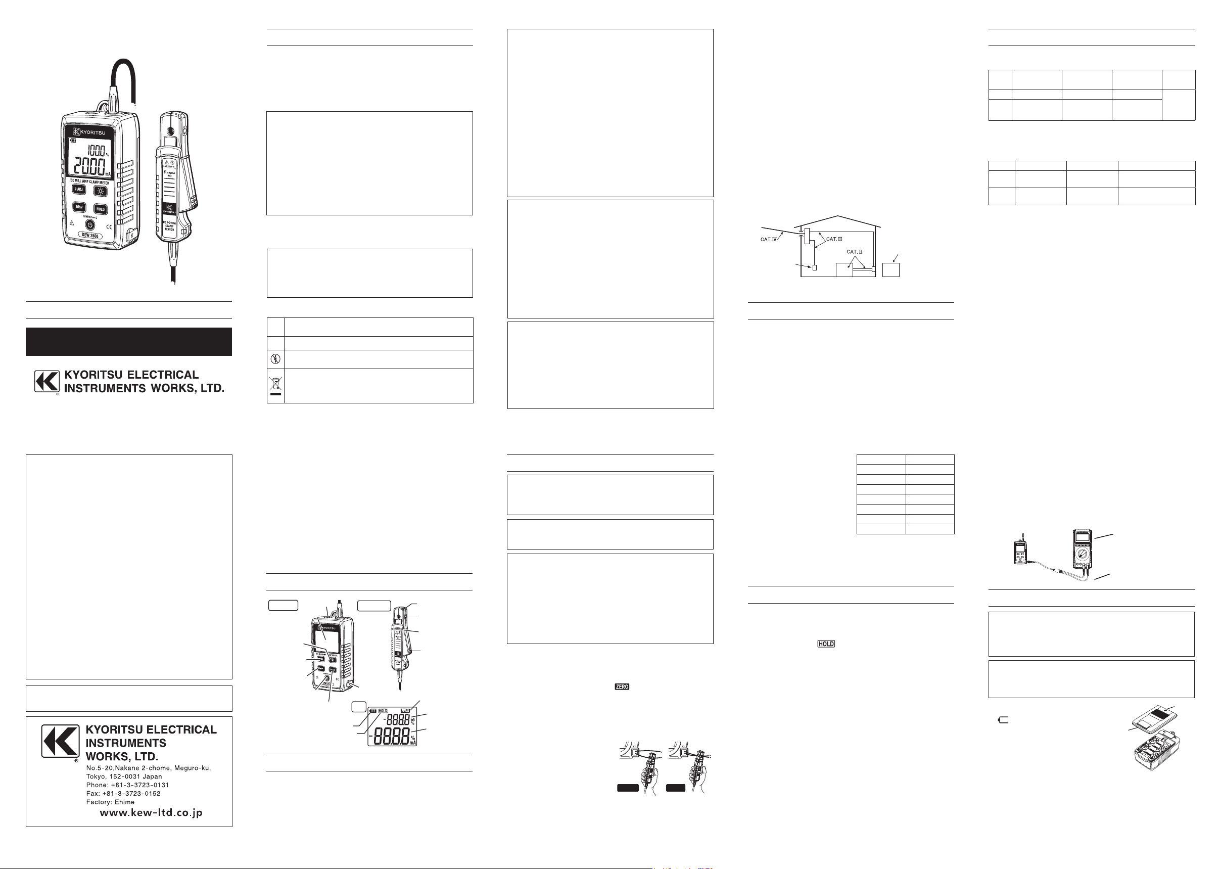
4.Instrument layout
5.Getting started
(1) Power on the instrument, and then check smooth opening and
closing of clamp sensor.
(2) Check the remaining battery level before making a measure-
ment. Press the Power button and get the instrument started.
When the battery empty in
dicator appears in the LCD, please
replace the batteries with new ones according to 8. Battery
replacement in this manual.
(3) Ensure that the Data hold function is not in active status.
6.Operating instructions
# WARNING
● Do not clamp onto the un-insulated conductor.
● Always use the dedicated analog output cord MODEL 7256
when utilizing the analog output function.
# DANGER
● Keep your fingers an
d han ds behind the barrier during a
measurement.
# CAUTION
● To avoid false reading, check that the Clamp sensor is clean
before starting to use the instrument.
● Bring the Clamp sensor close to the conductor under test
and zero adjust the display in order to minimize the influence
of electromagnetic waves.
● Take sufficien t care to n ot to appl y shoc k, v ib ra ti on o r
excessive force when opening and
closing the clamp sensor.
Otherwise, accurate measured results may not be obtained.
Please open and close the sensor lightly.
(1) Zero Adjustment
Perform zero adjustment prior to starting a measurement. With
the transformer jaws closed and without clamping them onto the
conductor, press the Zero ADJ. button.
Then the Zero adjustment mark
is shown on the LCD for
about one second.
(2) Measurement
Press the Jaw trigger to open the transformer jaws and clamp
them onto the conductor under test and take the reading on the
display. (See the figure below.)
Whe n the current flow s in th e
same direction as indicated by
the arrow mark on the jaws, the
polarity of the reading is positive
and vice versa.
* %(Span) display
The sub-display shows
percentage value as the basis of 4mA is
0% and 20mA is 100%. (at 20mA Range only) The percentage is
displayed on the main display by pressing the DISP button. In this
case, the current value is displayed on the sub-display.
* When connecting the Analog output cord to the instrument, the
sub-display shows OUT for 1 sec.
When making measurements for long periods of time:
- leave the instrument for the warm-up period of several tens of
minutes after powering it on, and then start a recording.
- readings will vary when the ambient temperature changes. In
this case, the temperature coefficients specified at clause 3 an
d
fluctuations at zero (about 20 counts fluctuate when temperature
changes by 10ºC) should be taken into consideration.
8.Battery replacement
# WARNING
● Ensur e t hat th e Clamp senso r is di sc onnecte d from th e
obje ct under test, and that the instrument is powered off
when openin g the Batter y compartment cover for batter y
replacement.
# CAUTION
● Do not mix new and old batteries or mix different types
of
batteries.
● Install batteries in correct polarity as marked inside.
Re pla ce b att er i es w ith the new
ones when the empty battery mark
is displ ayed on the LCD.
The LCD does not show anything,
ev en th e em pty ba t t e r y ma rk,
when the batteries are completely
exhausted.
[ How to replace batteries ]
(1) Power off the instrument.
(2) Lo osen the scre w a t t he back si de of th e inst rument and
remove the Battery compartment cover.
(3) Remove all the old batteries and install new ones, four size
AA batteries, in correct polarity. The use o
f alkaline batteries
(LR6) is recommended.
(4) Reattac h t he Batt ery comp ar tment co ve r a nd tighten th e
screw.
DC Milliamp Clamp Meter
KEW 2500
The table at the right shows the
rel ation ship betwe en %(Spa n)
values and the measured values
(mA).
T he p e r c en ta ge v a l u e i s
calculated based on the following
formula, assuming the measured
value as X.
Percentage = (|X| - 4.00)×6.25
Measured values (mA) Percentage display (%)
−20.00 100.0
0.00 −25.0
2.00 −12.5
4.00 0.0
12.00 50.0
20.00 100.0
100.0 −−−
* Over-limit indication
When the input exceeds the max measuring ra
nge (126.0mA),
"OL" or -OL (for negative values) is indicated on the display.
When the Range reaches to the 100mA, bars (---) are displayed
instead of the percentage value.
7.Other functions
7.1 Data Hold Function
This is a function to freeze the measured value on the display.
Press the Data hold button once to freeze the reading. The
reading will be held regardless of subsequent variation in inp
ut.
The Data hold mark "
" is indicated on the display while the
instrument is in the Data Hold mode. To exit Data Hold mode,
press the Data hold button again.
7.2 Auto-power-off function
The instrument automatically powers off about 10 min after the
last operation. This function is disabled while the cord is being
connected to the analog output terminal. To disable this function
at all times, hold down the Data hold butto
n while powering on the
instrument. The LCD shows P.oFF for about 1 sec immediately
after powering on the instrument. To restore this function, power
off once and power on again.
7.3 Backlight & LED light
Press the Light button to turn on or off the LED light and LCD
backlight. These lights automatically turn off after two minutes.
To disable the automatic light timeout, hold down the Light button
while powering on the instrument. The LCD shows L.oFF for
about 1 sec immediately after powering on the instrument. To
restore this function, power off once and power on again.
7.4 Analog output function
DC voltage signal corresponding to the measured result is output
from the Analog output terminal. (10mV/mA) It can be checked on
a recorder or a digital multi-meter connected to the instrument by
using MODEL7256 output cord.
correct wrong
Screw
Battery
compartment
cover
Zero ADJ.
button
DISP button
(to switch displays)
Light button
LED light
Data hold button
Power button
Trigger
LCD
Analog output
terminal
Transformer Jaws
Polarity mark
Barrier
Main unit
Clamp sensor
Battery level indicator
Hold mark
Zero ADJ. mark
Sub display
Main display
LCD
2-12 92-2078
DISTRIBUTOR
Kyoritsu reserves the rights to change specifications or designs
described in this manual without notice and without obligations.
To digital multimeter or recorder
Analog output
cord M-7256
 Loading...