

Page 1
9
KEW LEAKAGE CLAMP METERS
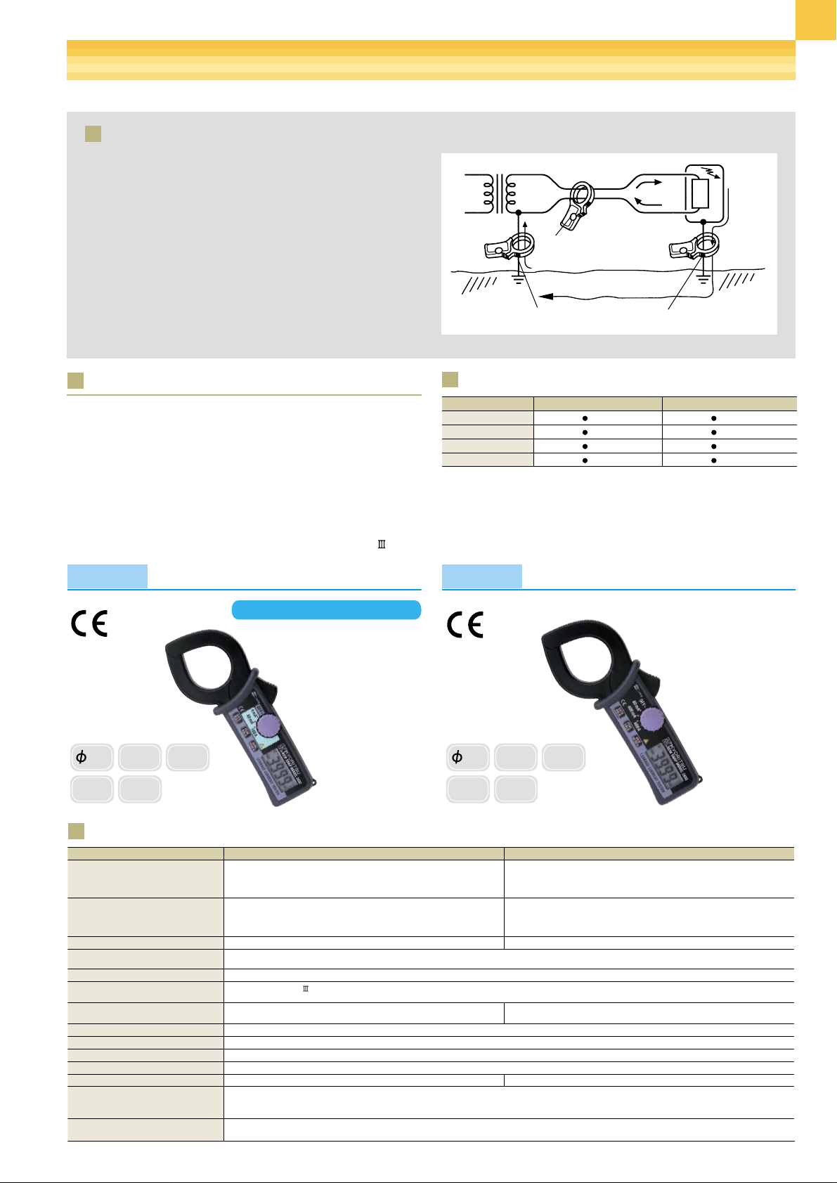
Broadly speaking, there are two methods of leakage current measurement. One is designed to measure leakage current by directly
clamping on an earthing conductor and the other is intended to
measure leakage current by clamping on two-way wires together.
Please refer to Fig.1 for respective measurement methods. The
principle of measurement involving the clamping of two-way wires
together is meant to find out the difference of current flowing
between the incoming wire and outgoing wire and display the
result. If there is no leakage on the load side, the instrument display reads zero. If the leakage occurs on the load side, the leakage
current will flow back into the power supply through earth, resulting
in the difference of current flowing between the two-way wires
which will then be displayed on the instrument as a value of leakage current.
Method of leakage current measurement
2432
MODEL
2433
MODEL Model 2432 Model 2433
AC A
(50/60Hz)
4/40mA/100A
±1%rdg±5dgt(4/40mA)
±1%rdg±5dgt(0
~
80A)
±5%rdg(80.1
~
100A)
40/400mA/400A
±1%rdg±5dgt(40/400mA)
±1%rdg±5dgt(0
~
350A)
±2%rdg(350.1
~
399.9A)
4/40mA/100A
±2.5%rdg±10dgt[20
~
1kHz] , ±1%rdg±5dgt[50/60Hz](4/40mA)
±2.5%rdg±10dgt[40
~
1kHz] , ±1%rdg±5dgt[50/60Hz](0~80A)
±10%rdg[40
~
1kHz] , ±5%rdg[50/60Hz](80.1~100A)
600V AC/DC (between line/neutral)
300V AC/DC (against earth)
40/400mA/400A
±2.5%rdg±10dgt[20
~
1kHz] , ±1%rdg±5dgt[50/60Hz](40/400mA)
±2.5%rdg±10dgt[40
~
1kHz] , ±1%rdg±5dgt[50/60Hz](0~350A)
±5%rdg[40
~
1kHz] , ±2%rdg[50/60Hz](350.1~399.9A)
AC A
(WIDE)
Frequency Response
Maximum
Circuit Voltage
Conductor Size
Safety Standard
Effect of External
Stray Magnetic Field
2mA AC approx. in proximity to a 15mm-dia
conductor carrying 100A AC
10mA AC approx. in proximity to a 15mm-dia
conductor carrying 100A AC
φ 40mm max.
Withstand Voltage 3700V AC for 1 minute
IEC61010-1 CAT. 300V Pollution Degree 2
IEC61010-2-032
Response Time Approx. 2 seconds
20Hz
~
1kHz(40Hz~1kHz:100A) 20Hz~1kHz(40Hz~1kHz:400A)
Power Source Two R03 or equivalent (DC1.5V) batteries
Dimensions 185(L)
×
81(W) × 32(D)mm
Weight 290g approx. 270g approx.
Accessories 9052 (Carrying Case)
R03(1.5V)
×
2
Instruction Manual
Optional 8004/8008 (Multi-Tran)
These Multi-Trans can not be used for leakage current measurement
Specifications
Fig.1 Method of leakage current measurement.
40
MAX
AC 100A
Resolution
0.001mA
Filter
PEAK
10ms
40
MAX
AC 400A
Resolution
0.01mA
Filter
PEAK
10ms
Selection Guide
•
Least affected by external stray magnetic field.
2mA AC approx. in proximity to a 15mm-dia conductor carrying
100A AC (2432) 10mA AC approx. in proximity to a 15mm-dia conductor carrying 100A AC (2433)
•
Frequency Selector Switch to eliminate the effect of harmonics.
•
Three AC current ranges:4mA/40mA/100A (2432)
40mA/400mA/400A (2433).
•
Data hold function.
•
Peak hold function.
•
Sleep function to save battery.
•
Designed to international safety standard IEC61010-1 CAT. 300V
Features
Power
Supply
Transformer
l1
l2
Measurement by clamping
two-way wires together
(leakage current lg(l
displayed)
Leakage Current lg
Measurement on earthing wire
(leakage current lg will be displayed)
1-l2)will be
Load
Leakage
Current
lg
MODEL
High Sensitive Model
MODEL 2432 2433
AC A 100A 400A
Data Hold
Peak Hold
Freg. Select
Page 2
10
KEW LEAKAGE CLAMP METERS
This is a full range of our leakage clamp meters.
Use of highly sensitive transformer jaws permits AC current
measurements in the order of milliamps. These instruments
can measure not only earth leakage current but also leakage
current flowing in live conductors of single and three phase
systems by directly clamping them together.
The most outstanding feature of the Kyoritsu leakage clamp
meters is that all models have a frequency selector switch to
check for the harmonic content of the current under test.
MODEL
2431
MODEL
2417
Selection Guide
•
Frequency Selector Switch to eliminate the effect of harmonics.
•
Three AC current ranges 20mA/200mA/200A.
•
20mA range with a minimum resolution of 0.01mA.
•
Auto power-off function (automatically turns off in about 10 minutes).
•
Rotary switch for easy one finger power-on and range selection.
•
Water and dust proof construction. The instrument is protected
against water and dust.
•
True RMS for accurate measurement of non-sinusoidal waveform current.
•
Selectable frequency response of 50/60Hz only or up to 1KHz.
•
Automatically turns power off in about 30 minutes to conserve battery life.
MODEL
2412
•
Digital clamp meter with tear drop shaped, medium size transformer
jaws specially designed for leakage current measurement.
•
Frequency filter switch to eliminate the effect of harmonics.
•
Output terminal for connection to recorders and facility to operate
from external power supply permit continuous leakage current monitoring.
MODEL
2414/2415
MODEL
2413F
•
Compact, truly portable, high performance digital leakage current clamp
meter.
•
200mA range with a minimum resolution of 0.01mA.
•
Frequency filter switch to eliminate
the effect of harmonics.
•
Extra wide transformer jaws are best
suited for clamping on all three or four
wires (3 phases) together for leakage
current measurement.
•
Frequency filter switch to eliminate
the effect of harmonics.
•
Peak hold function.
•
Analogue output terminal.
30
MAX
AC 100A
Resolution
0.01mA
Filter
AC
V
68
MAX
AC 1000A
Resolution
0.1mA
Filter
OUT
PUT
PEAK
10/100ms
24
MAX
AC 200A
Resolution
0.01mA
Filter
40
MAX
AC 500A
Resolution
0.01mA
Filter
OUT
PUT
External
Power Supply
AC
V
MODEL
2434
•
Least affected by external stray magnetic field.
20mA AC max. in proximity to a 15mm-dia conductor carrying 100A AC
•
Frequency Selector Switch to eliminate the effect of harmonics.
•
Data hold function
•
Sleep function to save battery
28
MAX
AC 100A
Resolution
0.1mA
Filter
40
MAX
AC 500A
Resolution
0.1mA
Filter WP
RMS
MODEL 2414/15 2413F 2431 2412 2417
AC A 100A 1000A 200A 500A 500A
AC V 500V 600V
Ω 200Ω
Data Hold
Peak Hold
Output AC/DC DC
Freq.Select
True RMS
2434
100A
Page 3

11
KEW LEAKAGE CLAMP METERS
MODEL Model 2414/2415 Model 2413F Model 2431 Model 2412 Model 2417 Model 2434
AC A
(50/60Hz)
20/200mA/100A(M-2414)
20mA/2/100A(M-2415)
±
1.5%rdg±2dgt(20/200mA/2A)
±
2%rdg±5dgt(100A)
200mA/2/20/200A/1000A
±
1.5%rdg±2dgt(200mA/2/20A)
±
2%rdg±2dgt(200A 0~500A)
±
5.5%rdg(501~1000A)
20/200mA/200A
±
3%rdg±5dgt(20/200mA/100A)
±
5%rdg±5dgt(200A)
20/200mA/2/20/200/500A
±
1.5%rdg±5dgt(20/200mA/2A)
±
2%rdg±5dgt(20/200A)
±
2.5%rdg±5dgt(500A)
200/2000mA/20/200/500A
(True RMS)
±
1.5%rdg±6dgt(20/2000mA)
±
2%rdg±6dgt(20/200A)
400mA/4/100A
±
2%rdg±4dgt
±
2.5%rdg±6dgt(500A)
AC A
(WIDE)
20/200mA/100A(M-2414)
20mA/2/100A(M-2415)
±
1.5%rdg±2dgt(20/200mA/2A)
±
2%rdg±5dgt(100A)
200mA/2/20/200A/1000A
±
1%rdg±2dgt
(200mA/2/20A)(50/60Hz)
±
2%rdg±2dgt(200A 0~500A)
±
5.5%rdg(501~1000A)
20/200mA/200A
±
2%rdg±4dgt(20/200mA/100A)
(50/60Hz)
±
5%rdg±6dgt(20/200mA/100A)
(40
~
400Hz)
±
5%rdg±4dgt(200A) (50/60Hz)
20/200mA/2/20/200/500A
±
1%rdg±3dgt(50/60Hz)
(20/200mA/2A)
±
1.5%rdg±3dgt
(50/60Hz)(20/200A)
±
2%rdg±3dgt(50/60Hz)(500A)
200/2000mA/20/200/500A
(True RMS)
±
3%rdg±4dgt(200mA/2/20A)
(50/60Hz)
400mA/4/100A
±
2%rdg±4dgt
(50/60Hz)
±
3%rdg±5dgt
(40-400Hz)
±
3.5%rdg±4dgt(200A 0~500A)
±
4%rdg±4dgt(500A)
AC V 500V
±
1.5%rdg±2dgt(50/60Hz)
±
2%rdg±5dgt(40Hz~1kHz)
600V
±
2%rdg±5dgt(50/60Hz)
±
3.5%rdg±5dgt(40Hz~1kHz)
Ω
200
Ω
±
1.5%rdg±5dgt
Conductor Size
φ
30mm max.
φ
68mm max.
φ
24mm max.
φ
40mm max.
φ
28mm max.
Safety Standard
Frequency Response 40Hz
~
1kHz 40Hz~1kHz 40~400Hz 40Hz~1kHz 40~400Hz
Output
AC/DC200mV against 2000 count
DC200mV against 2000 count
Withstand Voltage 2200V AC for 1 minute 3000V AC for 1 minute 1000V AC for 1 minute 3700V AC for 1 minute
Power Source R6P(AA)(1.5V
) × 2 6F22(9V) ×
1 LR-44(1.5V) × 2 6F22(9V) × 1 or AC Adaptor 6F22(9V)
R03(AAA) (1.5V) × 2
Effect of External
Stray Magnetic Field
φ
15mm 100A
7mA AC max. 10mA AC max. 10mA AC max. 10mA AC max. 10mA AC max. 20mA AC max.
×
1
Dimensions 173(L) × 80(W) × 32(D)mm 250(L) × 130(W) × 50(D)mm 149(L) × 60(W) × 26(D)mm 209(L) × 96(W) × 45(D)mm 169(L) × 75(W) × 40(D)mm
Weight 210g approx. 570g approx. 120g approx. 450g approx. 220g approx.
Accessories 7053(Test Leads)
9052(Carrying Case)
R6P(AA)
×
2
Instruction Manual
9064(Carrying Case)
6F22
×
1
Instruction Manual
9090(Carrying Case)
LR-44
×
2
Instruction Manual
7066(Test Leads)
9072(Carrying Case)
8025(Plug for Output Jack)
6F22
×
1
Instruction Manual
9079(Carrying Case) Carrying Case
6F22
×
1
Instruction Manual
R03
×
2
Instruction Manual
Optional 8004/8008(Multi-Tran)
8021(Energizer)
7073(2WAY Output Cord)
IEC61010-1 CAT. 300V
IEC61010-2-032
IEC61010-1 CAT. 300V
IEC61010-2-032
IEC61010-1 CAT. 300V
IEC61010-2-032
8004/8008(Multi-Tran)
8021(Energizer)
8004/8008(Multi-Tran)
8022(AC Adaptor)(110V)
8023(AC Adaptor)(220V)
7014(Output Probe)
8004/8008(Multi-Tran)
8004/8008(Multi-Tran)
These Multi-Trans can not be used for leakege current measurement.
IEC61010-1 CAT. 300V
IEC61010-2-032
Specifications
This switch is designed to select "WIDE" or "50/60Hz" range.
"WIDE" range covers a wide frequency band of 40Hz to 1kHz. AC
current having a fundamental waveform and harmonics can be
measured over this range. "50/60Hz" is restricted to a frequency
response of 40Hz to 100Hz and therefore permits measurement of
AC current of fundamental frequency only by filtering harmonic
content. When in doubt as to the presence of harmonics you can
identify it by using this frequency selector switch. To give an example, the following shows the results of AC current measurement on
an earthing wire within a switchbox where there is an inverter
based airconditioner is connected at summertime. Model 2414
reads 56mA AC with the frequency selector switch set at the
"WIDE" position as shown, while it displays 3mA at the "50/60Hz"
switch position. The difference between the two readings (56mA 3mA = 53mA) is considered leakage current caused by harmonics.
The test also found that this leakage current is flowing into single
phase, 3-wire circuits other than those connected with the inverters
in the building inspected.
High frequency selector switch
Most alternating currents and voltages are expressed in effective
values, which are also referred to as RMS(Root-Mean-Square)values. The effective value is the square root of the average of the
square of alternating current or voltage values.
Many clamp meters with rectifier type circuits have scales that are
calibrated in RMS values for AC measurements. But, they actually
measure the average value of input voltage or current, assuming
the voltage or current to be a sine wave.
The conversion factor for a sine wave, which is obtained by dividing the effective value by the average value, is 1.1. These instruments are in error if the input voltage or current has some other
shape than a sine wave.
True RMS value
CF: Crest Factor=Peak value/RMS value
DC=1
Sine wave=1.414
"WIDE"range - 56mA reading
"50/60Hz"range - 3mA reading
Fig. Results of AC current measurement on earthing wire within switch-
box by using Model 2414 on the 200mA range.
200
mA
100
0
0 10 20 30 40 50ms
20
mA
10
0
0 10 20 30 40 50ms
 Loading...