

Page 1
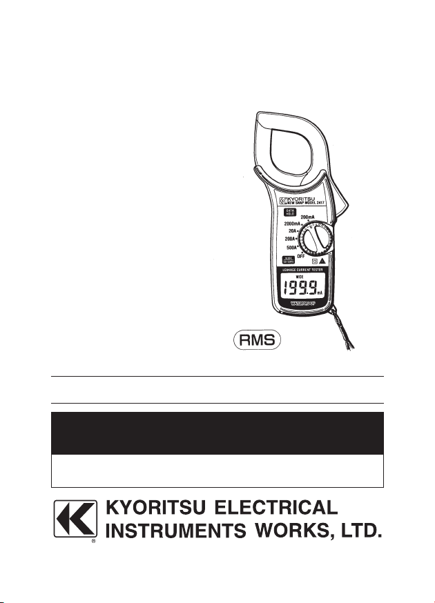
ALL WEATHER DIGITAL AC LEAKAGE CURRENT TESTER
KEW SNAP Series
MODEL 2417
INSTRUCTION MANUAL
Page 2

CONTENTS
1. SAFETY WARNINGS ・・・・・・・・・・・・・・・・・・・・・・・・・・・・・・・・・・・・1
2. FEATURES ・・・・・・・・・・・・・・・・・・・・・・・・・・・・・・・・・・・・・・・・・・・・・4
3. SPECIFICATIONS ・・・・・・・・・・・・・・・・・・・・・・・・・・・・・・・・・・・・・・5
4. INSTRUMENT LAYOUT ・・・・・・・・・・・・・・・・・・・・・・・・・・・・・・・・・ 7
5. PREPARATION FOR TESTS ・・・・・・・・・・・・・・・・・・・・・・・・・・・・・9
6. OPERATING INSTRUCTIONS ・・・・・・・・・・・・・・・・・・・・・・・・・・・10
6-1 CURRENT MEASUREMENTS ・・・・・・・・・・・・・・・・・・・・・・・10
6-2 FREQUENCY SELECTOR SWITCH ・・・・・・・・・・・・・・・・・12
6-3 DATA HOLD ・・・・・・・・・・・・・・・・・・・・・・・・・・・・・・・・・・・・・・・14
6-4 AUTOMATIC POWER OFF ・・・・・・・・・・・・・・・・・・・・・・・・・・14
7. BATTERY REPLACEMENT ・・・・・・・・・・・・・・・・・・・・・・・・・・・・・15
8. OPTIONAL ACCESSORIES ・・・・・・・・・・・・・・・・・・・・・・・・・・・・・16
Page 3

1
1. SAFETY WARNINGS
Make sure to read through this instruction manual before using this
instrument.
This instruction manual contains warnings and safety rules which
must be obser ved by the use to ensur e sa fe operation of the
instrument and to retain it in safe condition.
● The symbol
indicated on the instrument means that the user
must refer to related parts in the manual for safe operation of
the instrument. Be sure to carefully read the instruction following
each symbol in this manual.
DANGER is reserved for conditions and actions that are likely
to cause serious or fatal injury.
WARNING is reserved for conditions and actions that can cause
serious or fatal injury.
CAUTION is reserved for conditions and actions that can cause
bodily injury or instrument damage.
WARNING
● Read through and understand instructions contained in this
manual before starting using the instrument.
● Save and keep the manual handy to enable quick reference
whenever necessary.
● In order to avoid injury, or damage to the instrument or the
circuit under test, be sure to understand and follow all safety
instructions contained in the manual.
● Be sure to use the instrument only in its intended applications
an d t o f ol lo w mea su re me nt pr oc edures described in the
manual.
Page 4
2
Following symbols are used on the instrument and in the instruction
manual. Attention should be paid to each symbol to ensure your
safety.
Refer to the instructions in the manual.
This symbol is marked where the user must refer to the
instruction manual so as not to cause personal injury or
instrument damage.
Indicates an instrument with double or reinforced insulation.
DANGER
●Never make measurement on a circuit above 600V AC.
● Do not attempt to ma ke measuremen t in th e presence of
flammable gasses, fumes, vapor or dust. Otherwise, the use
of the instrument may cause sparking, which can lead to an
explosion.
● Transformer jaw tips are designed not to short the circuit under
test. If equipment under test has exposed conductive parts,
however, extra precau tion should be taken to minimize the
possibility of shorting.
● Never op en the bat tery compar tm ent co ve r when making
measurement.
● Never try to make measurement if any abnormal conditions,
such as broken Transformer jaws or case is noted.
● The instrument is be used only in its intended applications
or conditions. Otherwise,Safety functions equipped with the
instrument doesn't work, and instrument damage or serious
personal injury may be caused.
Page 5

3
WARNING
● Never attempt to make any measurement if any abnormal
conditions are noted, such as broken case, cracked test leads
and exposed metal parts.
● Do not install substitute parts or make any modification to the
instrument. Return the instrument to Kyoritsu or your distributor
for repair or re-calibration.
● Do not try to replace the battery if the surface of the instrument
is wet.
CAUTION
● Ma ke sure t ha t the funct io n sel ector swit ch is set to an
appropriate position before making measurement.
● Be sure to set the function selector switch to the OFFposition
after use. When the instrument will not be use for a long period
of time, place it in storage after removing the battery.
This is to avoid damage to the instrument by possible leakage
from the battery.
● Do not ex po se the instrument to th e direct sun, extr em e
temperatures or dew fall.
● Placing the instrument in temperatures of 60℃ or higher can
cause the instrument's case to deform and result in operation
failures.
Page 6

4
2. FEATURES
○ Model 2417 offers True RMS measurement capability.
○ Designed for measurements of AC Leakage and AC current with
five ranges from 200 mA to 500 A. AC 200 mA range provides a
high resolution of 0.1 mA.
○ Least affected by external magnetic field.
○ Provides dual frequency responses of fundamental 50/60Hz only
or up to 1kHz. The frequency response of up to 1kHz permits
measurements of current with harmonics superimposed on the
fundamental frequency. High frequency current from appliances
such as inverters, switching regulators etc. can therefore be
measured.
○ Data hold function to allow for easy readings in dimly lit or hard-
to-reach locations.
○ Large easy-to-read LCD display.
○ Automatic power off within 30 minutes to conserve battery life.
Page 7

5
3. SPECIFICATIONS
●AC current ranges
at 23±10℃ , 85% relative humidity
Ranges
Accuracy
Frequency Selector Switch
WIDE (40Hz-1kHz) position
50/60 Hz position
200mA 0-199.9mA
±1.0% rdg±4 dgt (50/60 Hz)
±1 .5% rdg±6 dgt
2000mA 0-1999mA
±3.0% rdg±4 dgt (40Hz-1kHz)
20A 0-19.99A
±1.5% rdg±4 dgt (50/60 Hz)
±2.0% rdg±6 dgt
200A 0-199.9A
±3.5% rdg±4 dgt (40 Hz-1kHz)
500A 0-500A
±2.0% rdg±4 dgt (50/60 Hz)
±2.5% rdg±6 dgt
±4.0% rdg±4 dgt (40Hz-1kHz)
Operating System: Dual Integration
Sensing: True RMS sensing
Digital Display: 3-1/2 di gi t l iq ui d crystal dis pl ay wi th
maximum reading of 1999
Overrange Indication: Numeral "1" on the highest digit flashes
Response Time: Approx. 2 second
Sample Rate: Approx. three times per second
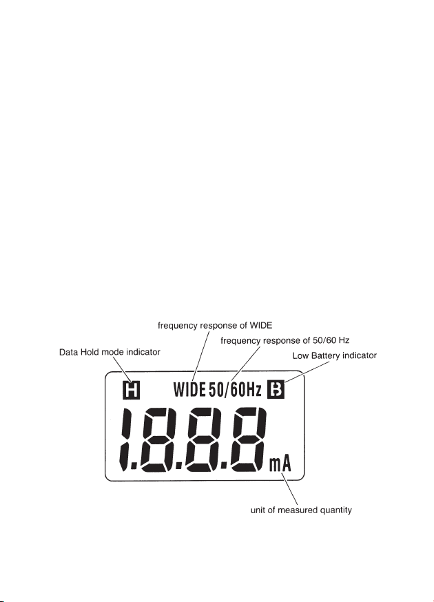
Data Hold: For all ranges. In Data Hold mode, "H"
symbol is displayed on the digital display
Low Battery Indicator: "B" symbol is displayed on the digital
display.
Storage Temperature
and Humidity:
-10 ℃~ 5 0℃ at 75% m a x , r e l a t iv e
humidity without condensing
Operating Temperature: 0~40℃
Power Source: one 6F22 (DC9 V) battery or equivalent
Current Consumption: Approx. 4 mA
Page 8

6
Auto Power Off: Automatically turns power off in approx.
30 m inu t es af ter t he in str u men t is
powered
Insulation Resistance: 10MΩ min. at 1000 V between electrical
circuit and housing case, and electrical
circuit and transformer jaws
Withstand Voltage:
3700 V AC for 1 minute between electrical
circuit and housing case as well as electrical
circuit and transformer jaws
Conductor Size: Approx. 40 mm diameter max.
Dimensions: 209 (L) x 96 (W) x 45 (D) mm
Weight: 450 g approx. (battery included)
Accessories: 6F22 battery
Carrying Case
Instruction manual
Optional Accessories: Multi-Tran Model 8004 and 8008
Page 9

7
4. INSTRUMENT LAYOUT
Fig. 1
Page 10
8
① Transformer Jaws
Pick up current flowing through the conductor.
② Jaw Trigger
Operates the transformer jaws. Press to open them.
③ Power/Range Switch
Selects ranges. Also, turns power on. Always turn the switch to
off after use.
④ Data Hold Push Button
Push to freeze a reading and push again to release it. In Data
Hold mode, "H" is displayed on the digital display.
⑤ Frequency Selector Switch
Selects frequency response of 50/60 Hz or up to 1 kHz WIDE.
⑥ Digital Display
Function symbols and decimal point are displayed according to
the Range Switch position.
Fig. 2
⑦ Safety Hand Strap
Page 11

9
5. PREPARATIONS FOR TESTS
WARNING
Always inspect your instrument and accessories for any
sign of damage or abnormality bef ore every use. If any
abnormal conditions exist (eg. cracked cases, display not
reading, etc.), do not attempt to conduct any tests.
5-1 Battery Check
To check the battery voltage set the Power/Range Selector Switch
to OFF position. If the display is clear without symbol "B" showing,
battery voltage is OK. If the display blanks or "B" is indicat ed,
replace the battery according to section 7 for Battery replacement.
NOTE
The instrument automatically turns power off approximately 30
minutes after it is turned on. Therefore the display may be
blank with the Power/Range Selector Switch set to On position.
To operate the instrument, set the switch back to OFF position
and then ON position.
5-2 Data Hold Switch
If the Data Hold Switch is pressed in (DATA HOLD mode), press to
release it.
Otherwise, the display remains frozen. When the instrument is in
DATA HOLD mode, "H" symbol is indicated on the display.
Page 12

10
6. OPERATING INSTRUCTIONS
6-1 Current Measurements
WARNING
● Do not make measurements where the potential is greater
than 600 V AC. This may cause shock hazard and damage
to the instrument or equipment under test.
● The Transformer Jaws are made of metal and their tips
are not insulated. Be especially careful about the hazard
of possible shorting where the equipment under test has
exposed metal parts.
● Do not open the battery compartment cover when making
measurements.
CAUTION
● Take sufficient care to avoid shock, vibration or excessive
force when handling the instrument. Otherwise, precisely
adjusted Transformer Jaws will be damaged.
● When Transformer Jaws do not fully close, never try to
close them by force, but make th em free to move and
try again. If a foreign substance is stuck in the jaw tips,
remove it. If the jaw tips have been deformed, correct so
that each tip is properly aligned. Otherwise, the jaws will
be damaged and warranty may not cover the repair cost.
Page 13

11
NOTE
● When making current measurements, keep the Transformer
Ja ws ful ly clo se d. Oth er wise, accura te measurements
cannot be taken.
Maximum conductor size is 40 mm in diameter.
● When measuring larger current, the Transformer Jaws may
buzz. This is not a fault and does not affect the accuracy
either.
(1) Set the Range Switch to the desired "A" or " mA" position.
(2) Select the desired frequency response. WIDE or 50/60 Hz,
with th e Frequency Selector Switch. (see sect ion 6-2 for
Frequency Selector Switch)
(3) Press the Trigger to open the Transformer Jaws and clamp
onto a co nductor or conductors as sho wn in Fig . 3. Take
th e readin g on t he dis pl ay. (Th is metho d als o permit s
measurements of leakage current flowing through earthing
conductors and very small current.)
Fig. 3
CAUTION
Do not exceed maximum allowable current on each current range.
(see section 3 for Specifications)
Page 14

12
NOTE
● For more accurate measurements, place the conductor at
the center of the closed jaws.
● When measuring current on a line or a grounded wire, clamp
onto one conductor only.
(4) When measuring out of balance leakage current, clamp onto
all conductors except a grounded wire as shown in Fig. 4.
Fig. 4
6-2. Frequency Selector Switch
Model 2417 measures AC currents of:
(1) 50/60 Hz fundamental frequency only with the Frequency
Selector Switch set to the 50/60 Hz position ("50/60 Hz" is
indicated on the display), or
(2) 40 Hz to 1 kHz with the Frequency Selector Switch set to the
WIDE position ("WIDE" is indicated on the display)
Page 15

13
Frequency respo nse of 40 Hz to 1 kHz permits measurements
of current with ha rmonics su perimpose d on th e fundamen ta l
fr eq ue ncy. Hig h f re qu ency current from app li ances suc h as
inverters, switching regulators etc. can therefore be measured.
NOTE
● Model 2417 hasa very good frequ ency response due to
the electrical property of the transformer jaws used for the
instruments.
Therefore, it measures AC current of not only 50 Hz or 60 Hz
fundamental wave form but also of higher frequencies and
harmonics superimpo sed on the fundamental frequency
when present in the circuit under test. To eliminate the effect
of noise from the high frequency and measure AC current
of 50 Hz or 60 Hz fundamental frequency, a filter circuit is
incorporated into the Model 2417 which works when the
frequency selector switch is set to the 50/60 Hz position.
It is designed to attenuate frequencies starting from around
100 Hz with an attenu ati on characteri sti c of approx. -24
dB/octave (signal strength declines to one sixteenth of that
at the initial frequen cy when it doubl ed). Recently there
has be en increa sed us age of power throu gh invert er s,
switching regulators, etc. When the high frequency noise
from such appliances leaks or flows into the ground through
capacitors not filtering completely, the earth leakage breaker
may not trip. In such a case the instruments may not give
current readings with the frequency selector switch at the
50/60 Hz position. Therefore, it is necessary to make current
measure ments with t he switch at the " WIDE" posit ion.
When in do ub t as to the pre sence of high freque ncies
an d har mo ni cs that a ff ec t AC c ur re nt measure me nt s,
take current readings with the switch at the 50/60 Hz and
"WIDE" positions respectively and then compare the results
obtained.
Page 16

14
6-3 Date Hold
Push the Data Hold Switch Button to freeze the reading. "H" symbol
is displayed on the digital display to indicate that the instrument is in
Data Hold mode.
Push the button again to exit from Data Hold mode.
6-4 Automatic Power Off
Model 2417 automatically turns power off In approx. 30 minutes
after it is turned on. To operate the instrument, set the Frequency
Selector Switch back to OFF position and then ON position.
Page 17

15
7. BATTERY REPLACEMENT
7-1 When to replace the battery
(1) When "B" symbol is displayed on the digital display.
(2) When the digital display does not read with the Power/Range
Selector Switch set to ON position.
7-2 Battery replacement
(1) Set the Power/Range Selector Switch to OFF position.
(2) Unscr ew and remove the batter y co mpartme nt cover as
shown in Fig. 5.
(3) Replace the ba ttery with a new 9 V b attery type 6F22 or
equivalent, observing correct polarity.
(4) Screw the battery compartment cover.
Fig.5
WARNING
Never replace the battery during measurement.
Page 18

16
8. OPTIONAL ACCESSORIES
8-1 Model 8004 and 8008
(Multi-Tran)
Model 8008 is a clamp-on current
transformer designed to measure
A C c u r r ent u p t o 3 000 A in
conjunction with a clamp meter. It
clamps on large bus-bars (up to
150 X 100 mm) and conductors
( u p t o 100 mm d ia me t e r ).
Model 8004 is also available for
AC cu rr ent mea su re ments up
to1000A on a conductor of max.
60 m m d i ame t e r. As sh o wn,
clamp on a conductor with Model
8008 or 8004, their p ickup coil
also clamped with Model 2417.
T h e n t a k e th e re a d i n g and
multiply it by 10.
NOTE
The s e M u lti- Tra n ' s can n o t
be used for lea ka ge cu rr ent
measurement.
Page 19

17
MEMO
Page 20

07-02 92-1313A
DISTRIBUTOR
 Loading...