

Page 1
取扱説明書
INSTRUCTION MANUAL
デジタルクランプメーター
DIGITAL CLAMP METER
KEW2200
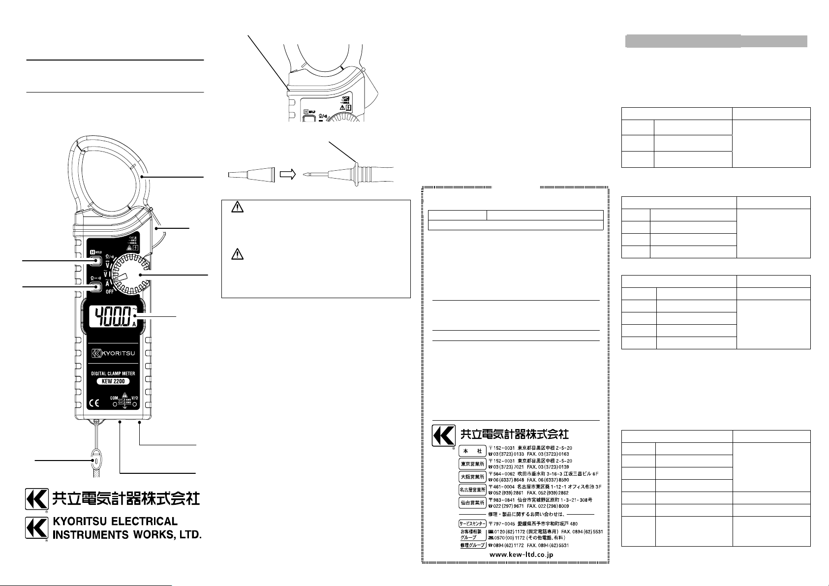
データホールドキー
Data Hold Key
モードキー
Mode Key
スナップバンド
Snap Band
04-11 92-2063B
電流センサ
Current Sensor
トリガー
Trigger
ファンクションスイッチ
Function Switch
LCD
V/Ω 端子
V/Ω Terminal
COM 端子
COM Terminal
本体のバリア / Barrier of Instrument body
測定コードのバリア / Barrier of Test Leads
キャップ / Cap
警告
本製品を使用する前に、必ずこの取扱説明
書をよく読んで理解してください。
WARNING
Read through and understand the
instructions contained in this manual
before using the instrument.
この説明書に記載されている事項を断り無く変更
する事がありますのでご了承ください。
本製品には保証書が添付されておりますので、保証
期間中の故障については保証規定をお読みになり
ご利用ください。
保証規定
保証期間中に生じました故障は、以下の場合を除き
無償で修理いたします。
1. 取扱説明書によらない不適切な取扱い、使用方
法、保管方法が原因で生じた故障。
2. お買い上げ後の持ち運びや輸送の間に、落下させ
るなど異常な衝撃が加わって生じた故障。
3. 弊社のサービス担当者以外の改造、修理、オーバ
ーホールが原因で生じた故障。
4. 火災、地震、水害、公害およびその他の天変地異
が原因で生じた故障。
5. 傷など外観上の変化。
6. その他弊社の責任とみなされない故障。
7. 電池など消耗品の交換、補充。
8. 保証書のご提出がない場合。
◎ご注意
弊社で故障状態の確認をさせていただき、上記に該
当する場合は有償とさせていただきます。電池の消
耗、測定コードの断線ではないことを確認してから、
輸送途中に損傷が生じないように充分に梱包を施
し、弊社サービスセンターまたは販売店宛にお送り
ください。
〒797-0045 愛媛県西予市宇和町坂戸 480
共立電気計器株式会社
サービスセンター 修理グループ
TEL. 0894-62-1172
FAX. 0894-62-5531
This warranty is valid only in Japan.
KEW 2200 製造番号
保証期間 ご購入日( 年 月 日)よ り 1 年間
共立製品を お買い上げいただき あり がと う ご ざい
ます。 保証期間内に通常のお取扱いで万一故障が
生じ た 場合は
いたし ます
本書を 添付の上ご依頼く ださ い。
お名前
ご住所 〒
お電話番号( ) -( ) -( )
◎保証規定を よ く お読みく ださ い。
◎本保証書は日本国内でのみ有効です。
◎本保証書の再発行はいた し かねま すの で 、 大切
に保管し て く だ さ い 。
販売店名
保証書
,
裏面の保証規定によ り 無償で 修理
。
JAPANESE / ENGLISH
1. 仕様 /Specification
確度保証 / Accuracy guaranteed
レンジの 100%以下 / 100% or less of range
温度 / Temperature 23 ± 5°C
湿度 / Humidity 45
ACA(オートレンジ / Auto Range)
レンジ / Range 確度 / Accuracy
40A 0.00, 0.03-41.99A
400A 32.0-419.9A
1000A 320-1049A
入力保護電流 / Input protective current :AC1200A
ACV(オートレンジ / Auto Range)
レンジ / Range 確度 / Accuracy
4V 0.000, 0.005-4.199V
40V 3.20-41.99V
400V 32.0-419.9V
600V 320-629V
DCV(オートレンジ / Auto Range)
レンジ / Range 確度 / Accuracy
400mV ±0.0-±419.9mV *1
4V ±0.320-±4.199V
40V ±3.20-±41.99V
400V ±32.0-±419.9V
600V ±320-±629V
*1 : 確度保証外 / Accuracy is not guaranteed
ACV/DCV 入力インピーダンス / input impedance
:>100MΩ (400mV Range)
:11MΩ (4V Range)
:10MΩ (40/400/600V Range)
抵抗 / Resistance(オートレンジ/ Auto Range)
導通 / Continuity
レンジ / Range 確度 / Accuracy
400Ω 0.0-419.9Ω
4kΩ 0.320-4.199 kΩ
40kΩ 3.20-41.99 kΩ
400kΩ 32.0-419.9 kΩ
4MΩ 0.320-4.199 MΩ ±4.0%rdg±4dgt
40MΩ 3.20-41.99 MΩ ±8.0%rdg±4dgt
導通
Cont.
開放電圧 / Open-loop voltage
:<3.4V (400Ω / Cont Range)
-419.9Ω
0.0
- 75%
±1.4 %rdg±6dgt
(50/60Hz)
±1.6 %rdg±6dgt
-65Hz)
(45
±1.8 %rdg±7dgt
-65Hz)
(45
±2.3 %rdg±8dgt
-500Hz)
(65
±1.0%rdg±3dgt
±2.0%rdg±4dgt
ブザーしきい値 /
Bz threshold value
50±30Ω
Page 2
:0.7V typ (4kΩ Range)
ACV
V
A
:0.47V typ (40k
入力保護電圧 / Input protective voltage
:AC/DC600V 10 秒間 / 10 sec
●動作方式 / Measuring method
2重積分方式 / Dual integration
●入力オーバー表示 / Over-range indication
OL
●測定周期 / Measurement cycle
毎秒 2.5 回 / 2.5 times per second
●適応規格 / Applicable Standards
IEC/EN 61010-1/ 61010-2-032/ 61010-031
汚染度 2 / Pollution degree 2
屋内使用 / Indoor use
高度 2000m 以下 / Altitude up to 2000m
電流測定部 / Current measurement section
CAT.III 600V
電圧測定部 / Voltage measurement section
CAT.II 600V / CAT.III 300V
EN61326 (EMC)
RF電磁界 3V/m において確度の 5 倍以内
In the radio-frequency electromagnetic field of
3V/m, accuracy is within five times the rated
accuracy.
●耐電圧 / Withstand voltage
AC5320Vrms 5 秒間 電流センサと外装間
AC3540Vrms 5 秒間 電気回路と外装間
AC5320Vrms 5sec between Current sensor
AC3540Vrms 5sec between circuit and enclosure
●絶縁抵抗 / Insulation resistance
>100MΩ /1000V 電気回路と外装間
between enclosure and electrical circuit
●動作温湿度範囲
0~40°C 相対湿度 85%以下(結露しないこと)
Operating Temperature and humidity range
0 to 40°C 85%RH or less (no condensation)
●保存温湿度範囲
-20~60°C 相対湿度 85%以下(結露しないこと)
Storage Temperature and humidity range
-20 to 60°C 85%RH or less (no condensation)
●電源 / Power source
DC3V:単 4 形乾電池×2 / R03/LR03 (AAA) ×2
●消費電流 / Current consumption
< 3mA
●連続使用時間 / Battery life
約 350 時間(ACA、連続、無負荷)
/ Approx. 350 hours (ACA, continuous, no load)
●外形寸法、質量 / Dimension, Weight
190(L)×68(W)×20(D)mm
approx. 120g(電池含 / including batteries)
●付属品 / Accessories
測定コード/ Test leads Model 7107A 1set
電池 / Battery R03(AAA) 2pcs
取扱説明書 / Instruction manual 1pce
- 40MΩ Range)
and enclosure
携帯ケース / Carrying case Model 9160 1pce
スナップバンド / Snap band 1pce
2. その他の機能 / Other Function
●データホールド / Data Hold
ホールドキーを押すと測定値が保持されます。
解除は再度ホールドキーを押します。
Press the Data Hold Key to freeze the reading.
Press the Data Hold Key again to release the
freezing display.
LCD 上に“ ” 表示
/ indicated “ ” on LCD
●電池電圧低下表示 / Low battery indication
2.3±0.15V 以下で LCD 上に“ ” 表示
indicated “ ” on LCD at 2.3±0.15V or less
●スリープ機能 / Sleep Function
スイッチ/キー操作後約 10 分でスリープ状態。
データホールドキーを押しながら電源 ONでスリ
ープ機能解除(LCD に" "が 2 秒間表示)。
Automatically powered off in about 10min after.
To disable the sleep function, power the
instrument on with the Data Hold Key pressed.
(indicated " " for about 2 seconds on LCD)
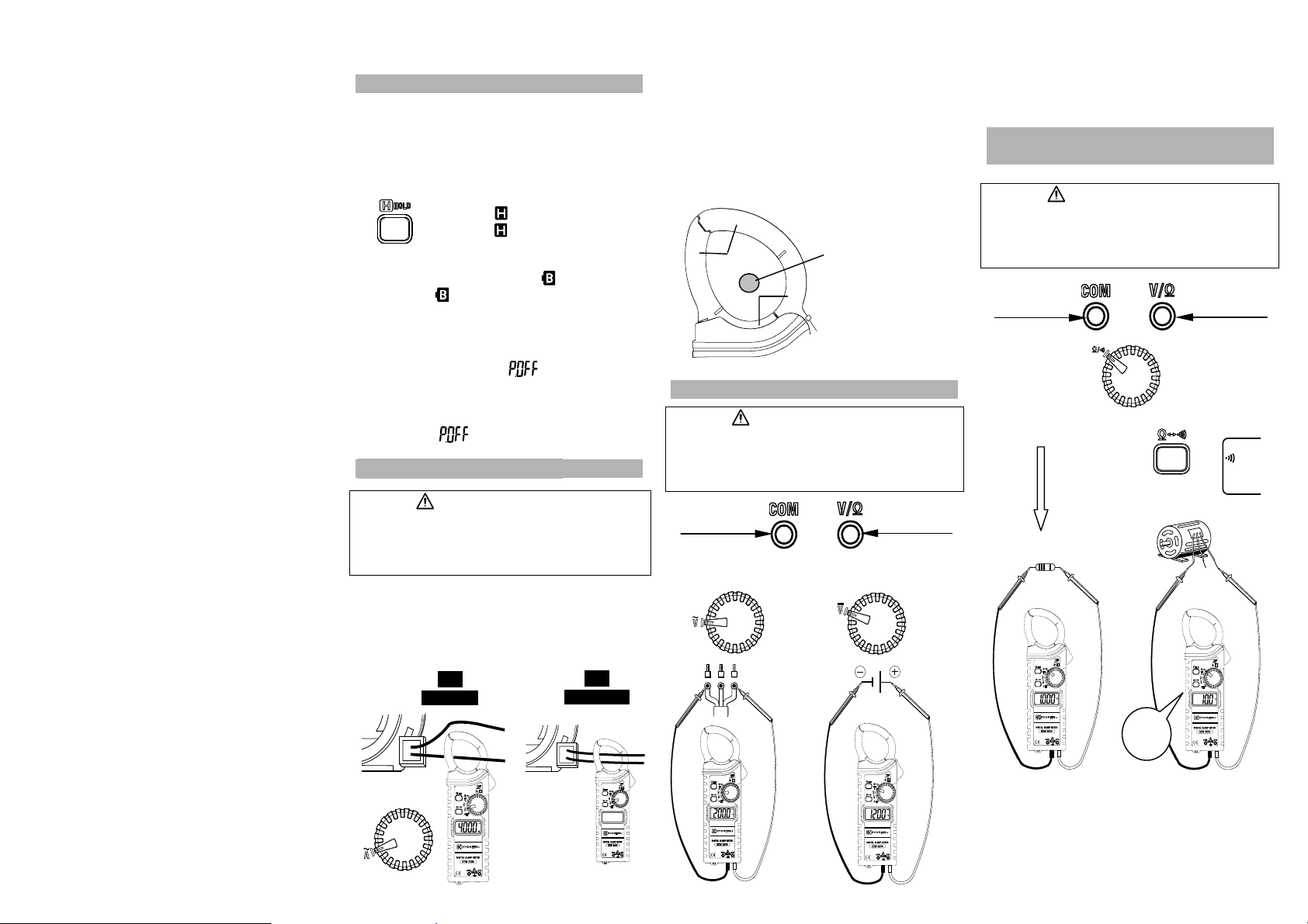
3. ACA 測定 / Measurement
危険 / DANGER
測定を行うときは、必ず測定コードを本体から外し
てください。
Never measure current while the test leads are
inserted into the V/Ω and/or COM Terminals.
トリガーを押して電流センサ先端を開き被測定導
体(最大φ33mm)が電流センサの中心になるように
クランプしてください。
Press the trigger to open the Current Sensor and
clamp the one conductor (Dia. 33mm max.) under
test.
正
Correct
誤
Incorrect
注記 / NOTE
確度保証は電流センサの中心(Aゾーン)で測定し
たときが対象です。B ゾーンでは確度に 4%を追加
します。C ゾーンの測定値は参考値(確度保証外)
です。
Measurement accuracy is guaranteed when the
measured object is placed at the center (zone A) of
the Current Sensor. In zone B, 4% of tolerance
should be added to the specified accuracy. In zone
C, measured values should be considered as
reference values (Accuracy is not guaranteed).
C
4. ACV/DCV 測定 / Measurement
B
B
C
中心(A ゾーン)
Center (zone A)
危険 / DANGER
600V 以上の電位回路では、絶対に測定しないでく
ださい。
Never make measurement on a circuit in w hich
voltage over 600V exists.
測定コード黒
Black test lead
測定コード赤
Red test lead
DC
黒(-)
Black(-)
赤(+)
Red(+)
注記 / NOTE
DCV 測定において、測定コードを逆接続すると、
LCD 上に” - “が表示されます。
If the connection is reversed, the LCD indicates the
“ - “ mark (DCV measurement).
5. 抵抗(導通)測定
Resistance(Continuity ) Measurement
警告 / WARNING
測定の前には、本体に電圧が印加されないよう被測
定物(回路)の電源を切ってください。
Never use the instrument on an energized
circuit.
測定コード
Test lead
抵抗
Resistance
押す / Press
♪
50±30Ω以下でブザーオン。
Beep less than 50±30Ω.
測定コード
Test lead
導通
Continuity
LCD
注記 / NOTE
測定コードがオープン状態では”OL”を表示します。
LCD indicates ”OL” when the test leads are open.
Page 3

ENGLISH
6. Safety Warnings
This instrument has been designed, manufactured
and tested according to IEC 61010: Safety
requirements for Electronic Measuring apparatus,
and delivered in the best condition after passed the
inspection. This instruction manual contains
warnings and safety rules which must be observed
by the user to ensure safe operation of the
instrument and retain it in safe condition. Therefore,
read through these operating instructions before
using the instrument.
WARNING
● Read through and understand the instructions
contained in this manual before using the
instrument.
● Keep the manual at hand to enable quick
reference whenever necessary.
● The instrument is to be used only in its intended
applications.
● Understand and follow all the safety instructions
contained in the manual.
● It is essential that the above instructions are
adhered to.
● Failure to follow the above instructions may
impair the protection provided by the instrument
and test leads, and may cause injury, instrument
damage and/or damage to equipment under test.
The symbol indicated on the instrument means
that the user must refer to the related parts in the
manual for safe operation of the instrument. It is
essential to read the instructions wherever the
symbol appears in the manual.
DANGER is reserved for conditions and
actions that are likely to cause serious or fatal
injury.
WARNING is reserved for conditions and
actions that can cause serious or fatal injury.
CAUTION is reserved for conditions and
actions that can cause injury or instrument
damage.
● Marks listed below are used on this instrument.
User must refer to the manual.
Instrument with double or reinforced insulation
Indicates that this instrument can clamp on
bare conductors when measuring a voltage
corresponding to the applicable measurement
category, which is marked next to this symbol.
AC
DC
Ground (Earth)
This instrument is subject to WEEE Directive
(2002/96/EC). Please contact our dealer near
you at disposal.
Measurement Category
CA T.II
Primary electrical circuits of equipment connected
to an AC electrical outlet by a power cord.
CA T.III
Primary electrical circuits of the equipment
connected directly to the distribution panel, and
feeders from the distribution panel to outlets.
CA T.IV
The circuit from the service drop to the service
entrance, and to the power meter and primary over
current protection device(distribution panel).
Current measurement section of this
instrument is designed for CAT.III 600V
and Voltage measurement section is for
CAT.III 300V / CAT.II 600V respectively.
Test leads 7107A with the Cap is designed
for CAT.IV 600V / CAT.III 1000V and without
the Cap is for CAT.II 1000V.
DANGER
● Never make measurement on a circuit in which
voltage over AC/DC600V exists.
● Do not attempt to make measurement in the
presence of flammable gasses. Otherwise, the
use of the instrument may cause sparking, which
can lead to an explosion.
● Never attempt to use the instrument if its surface
or your hand is wet.
● Do not exceed the maximum allowable input of
any measuring range.
● Never open the Battery cover during a
measurement.
● To avoid electrical shock by touching the
equipment under test or its surroundings,
be sure to wear insulated protective gear.
● Never measure current while the test leads are
inserted into the input terminals.
● Barriers on the instrument body and the test leads
provide protection to keep your fingers and
hands from touching an object under test.
Keep your fingers and hands behind the barriers
during measurement.
WARNING
● Never attempt to make measurement if any
abnormal conditions, such as broken case and
exposed metal parts are found on the instrument
or test leads.
● Verify proper operation on a known source before
use or taking action as a result of the indication
of the instrument.
●
Firmly attach the Caps to the test leads
when performing measurements at
CAT.III or higher test environment.
When KEW2200 and the test leads are
combined and used together, whichever
is lower category & voltage to earth
either of them belong to is applied.
● Do not rotate the Function Switch while the test
leads are being connected.
● Do not install substitute parts or make any
modification to the instrument. For repair or
re-calibration, return the instrument to your local
distributor from where it was purchased.
CAUTION
● Use of this instrument is limited to domestic,
commercial and light industry applications.
If equipments generating strong electromagnetic
Interference or strong magnetic fields due to
large currents exist nearly, malfunctions of the
instrument may be caused.
● Set the Function Switch to an appropriate
position before starting measurement.
● Firmly insert the test leads.
● The LCD shows some readings at the ACV and
the DCV ranges even while the test leads are
open. And, it may show some digits instead of 0
when short-circuiting the test leads. However,
these phenomena don’t affect measurement
results.
● This instrument isn’t dust & water proofed.
Keep away from dust and water.
● Be sure to power off the instrument after use.
When the instrument will not be in use for a long
period, place it in storage after removing the
batteries.
● Do not expose the instrument to the direct sun,
high temperature and humidity or dewfall.
● Use a cloth dipped in water or neutral detergent
for cleaning the instrument. Do not use abrasives
or solvents.
7. Battery Replacement
WARNING
● Replace the batteries when a Low Battery
Voltage warning " " mark(< 2.3±0.15V) is
indicated on the LCD. Otherwise, precise
measurement cannot be made. Note that when
the battery is completely exhausted, the LCD
goes blank without showing " " mark.
● Do not try to replace the batteries if the surface of
the instrument is wet.
● Disconnect the test leads from the object under
test and power off the instrument before opening
the Battery Compartment Cover for Battery
replacement.
CAUTION
● Do not mix old and new batteries.
● Install batteries in correct polarity as indicated in
the Battery Compartment.
(1) Set the Function Switch to "OFF" position.
(2) Unscrew and remove the Battery Compartment
Cover on the bottom of the instrument.
(3) Replace the batteries observing correct polarity.
Use new two R03/LR03 (AAA) 1.5V batteries.
(4) Install the Battery Compartment and tighten the
screws.
DISTRIBUTOR
Kyoritsu reserves the rights to change specifications
or designs described in this manual without notice and
without obligations.
 Loading...