

Page 1

DIGITAL MULTIMETER
WITH
AC/DC CLAMP SENSOR
KEW MATE 2012R
This instrument satisfies the marking requirement defined
in the WEE E Directive. This s ymbo l indi cate s sepa rate
collection for electrical and electronic equipment.
This marking means they shall be sorted out and collected
as ordained in DIRECTIVE 2006/66/EC.
This directive is vali d o nly in the EU. When you remove
batteries from this product and dispose them, discard them
in accordance with domestic law concerning disposal. Take
a right action on waste batteries, because the collection
system in the EU on waste batteries are regulated.
#
WARNING
●Measurement Category(CAT)
The restrict ions o n the maximum v oltage level for which
the this product can be used, depend on the measurement
categories specified by the safety standards.
Do not apply any input level higher than maximum allowable
input.
AC/DC 600V CAT II AC/DC300V CAT III
CAT II
Appliances, portable equipment, ect. For measurements
per formed on circuits direc tly connecte
d to the low
voltage installation.
CAT III
D is tr i bu ti o n boa rd, c ir c ui t br ea ker , e ct . Fo r
measurements performed in the building installation.
#
DANGER
● Never make measurement on circuits with a maximum voltage
difference of 600V or greater between conductors (300V or
greater between a conductor and ground).
● Do not attempt to make mea surement in the presen ce of
flammable gasses.
Otherwise, the use of the instrument may cause sparking,
which leads to an explosion.
● Never attempt to use the instrument if its surface or your hand
is wet.
●
Do not exceed the maximu m allowable input of measuri ng
ranges.
● Never open the battery compartment cover while making
measurement.
● Never try to make measurement if any abnormal conditions,
such as broken Clamp Sensor or case is noted.
● The instrument is to be used only in its intended applications or
conditions.
Otherwise, safety function s equip ped with the instrument
doesnt work, and instrume
nt damage or serious persona l
injury may be caused.
1.SAFETY WARNINGS
This instrument has been designed and tested a ccording to
IEC P ublicat ion 61010: Safe ty Req uire ments for Elec tron ic
Measuring Apparatus. This instruction manual contains warnings
and safety rules which must be observed by the user to ensure
safe operation of the instrument and to retain it in safe condition.
Therefore, read through t hese operating instructions before
starting usin
g the instrument.
# WARNING
● Read through and understand instructions contained in this
manual before starting using the instrument.
● Save and keep the manual handy to enable quick reference
whenever necessary.
● Be sure to use the instrument only in its intended applications
and to follow measureme nt procedures described in the
manual.
● Be sure to understan d and follow all safe ty instructions
contained in the manua
l.
Failure to follow the above instructions may cause injury, damage
to the instrument and/or damage to equipment under test.
The symbol # indicated on the instrument means that the user
must refer to related parts of the manual for safe operation of
the instrument. Be sure to carefully read the instructions following
each # symbol in this manual.
#
DANGER:is reserved for conditions and actions that are
likely to cause serious or fatal injury.
#
WARNING:is reserved for conditions and actions that can
cause serious or fatal injury.
#
CAUTION:is reserved for conditions and actions that can
cause minor injury or instrument damage.
Fo llo win g sym bol s are used on the ins trument and in the
instruction manual. Attention should be paid to each symbol t
o
ensure your safety.
#
Refer to the instructions in the manual.
This symbol is marked where the user must refer to the
instruction manual so as not to cause personal injury or
instrument damage.
Indicates an instrument with double or reinforced insulation.
Indicates that this instrument can clamp on bare conductors
when measuring a voltage corresponding to the applicable
Measurement category, which is marked next to this symbol.
Indicates AC (Alternating Current).
Indicates DC (Direct Current).
#
WARNING
● Never attempt to make any measurement, if any abnormal
conditions are noted, such as broken case, cracked test leads
or Clamp Sensor Cable and exposed metal parts or internal
wiring.
● Do not turn the Function Selector Switch while the test leads
are connected to the circuit under test.
● Do not install substitute parts or make any modification to
the instrumen t. Return the instrument to
Kyo ritsu or your
distributor for repair or re-calibration.
● Do not try to replace the batteries if the sur face of the
instrument is wet.
● Alw ays dis connect the clam p sensor and the test lead s
from t he circ uit under test and swit ch off the instrument
before opening the battery compar tment cover for battery
replacement.
● A cap is provided on the tip of a test lead. Use a test lead with
the cap on fo
r safety.
#
CAUTION
● Make sure that t he Func tion Selector Swi tch is set to an
appropriate position before making measurement.
● Always make sure to place the test leads in the holster before
making current measurement.
● Do not expose the ins trum ent to the dire ct sun, extreme
temperatures or dew fall.
● This instrument isn't dust & water proofed. Keep away from
dust and water.
● Be sure to s et the Function Sele
ctor Switch to the "OFF"
position after use. When the instrument will not be used for
a long period of time, place it in storage after removing the
batteries.
● Use a damp cloth and detergent for cleaning the instrument.
Do not use abrasives or solvents.
3.SPECIFICATIONS
● Measurin g R anges and Accuracy (at 23 ℃ ±5 ℃ , relative
humidity75% or less)
AC Current A (RMS value detection) Maximum Input Current : 120A
Range Display range Allowable input Accuracy
60A 0.00~60.39A
0.00~60.00Arms
(85Apeak or less)
±2.0%rdg±5dgt
(45~65Hz)
(sine wave)
120A 0.0~603.9A
0.0~120.0Arms
(170Apeak or less)
※ For non-sinusoidal waveforms, add ±(2% of reading + 2% of
full scale), for Crest factor<2.5.
DC Current A Maximum Input Current : 120A
Range Display range Allowable input Accuracy
60A ±0.00~60.39A ±0.00~60.00A ±2.0%rdg±8dgt
120A ±0.0~603.9A ±0.0~120.0A ±2.0%rdg±5dgt
AC Voltage V (RMS value detection, Auto-range) Maximum Input Voltage : 600V
Range Display range Allowable input Accuracy
6V 0.000~6.039V
0.300~600.0Vrms
(850Vpeak or less)
±1.5%rdg±5dgt
(45~400Hz)
(sine wave)
60V 5.60~60.39V
600V 56.0~603.9V
※Input Impedance:approx. 10MΩ <200pF
※ For non-sinusoidal waveforms, add ±(2% of reading + 2% of
full scale), for Crest factor<2.5.
DC Voltage V (Auto-range) Maximum Input Voltage : 600V
Range Display range Allowable input Accuracy
600mV ±0.0~603.9mV
±0.0m~600.0V ±1.0%rdg±3dgt
6V ±0.560~6.039V
60V ±5.60~60.39V
600V ±56.0~603.9V
※Input Impedance:approx. 10MΩ
Resistance Ω (Auto-range)
Range Display range Allowable input Accuracy
600Ω 0.0~603.9Ω
0.0Ω~60.00MΩ
±1.0%rdg±5dgt
6kΩ 0.560~6.039kΩ
60kΩ 5.60~60.39kΩ
600kΩ 56.0~603.9kΩ
6MΩ
0.560~6.039MΩ
±2.0%rdg±5dgt
60MΩ 5.60~60.39MΩ ±3.0%rdg±5dgt
※ Open-loop Voltage:approx.0.6V, Measuring Current : 0.3mA or
less
Continuity
Range Display range Allowable input Accuracy
600Ω 0.0~603.9Ω 0.0~600.0Ω ±1.0%rdg±5dgt
※The buzzer turns on for resistances lower than 35±25Ω.
※ Open-loop Voltage:approx.0.6V, Measuring Current : 0.3mA
or less
Diode
Range Display range Allowable input Accuracy
2V 0.000~1.999V 0.000~1.999V ±3.0%rdg±5dgt
※Open-loop Voltage:approx.2.7V
Capacitor
(Auto-range)
Range Display range Allowable input Accuracy
40nF 0.00~40.39nF the accuracy is not guaranteed
400nF 36.0~403.9nF
40.0n~40.00μF
±2.5%rdg±10dgt4μF 0.360~4.039μF
40μF 3.60~40.39μF
400μF 36.0~403.9μF
the accuracy is not guaranteed
4000μF 360~4039μF
Frequency Hz ( AC Current ) (Auto-range)
Range Display range Allowable input Accuracy
10Hz 0.000~9.999Hz The accuracy is not guaranteed
100Hz 9.00~99.99Hz
9.00Hz~400.0Hz
±0.2%rdg±2dgt
1000Hz
90.0~400.0Hz ±0.1%rdg±1dgt
400.1~999.9Hz
The accuracy is not guaranteed
10kHz 0.900~9.999kHz
100kHz 9.00~99.99kHz
1000kHz 90.0~999.9kHz
10MHz 0.900~9.999MHz
※Input Current:more than 6A
Frequency Hz ( AC Voltage ) (Auto-range)
Range Display range Allowable input Accuracy
10Hz 0.000~9.999Hz The accuracy is not guaranteed
100Hz 9.00~99.99Hz
9.00Hz~300.0kHz
±0.2%rdg±2dgt
1000Hz 90.0~999.9Hz
±0.1%rdg±1dgt
10kHz 0.900~9.999kHz
100kHz 9.00~99.99kHz
300kHz 90.0~300.0kHz
1000kHz 300.1~999.9kHz
The accuracy is not guaranteed
10MHz 0.900~9.999MHz
※ Input Voltage:more than 6V (~10kHz) , more than 20V (10k
~
300kHz)
※Input Impedance:approx. 900kΩ
Note:◇ The sy
mbol of "―" in the above table means that the
instrument only displays the value, but the accuracy, the
proper operation and the safety are not guaranteed.
2.FEATURES
● Permits AC/DC current measurement up to 120A usin g a
clamp sensor that comes standard with the instrument
● Clamp sensor for ease of use in crowded cable areas and
other tight places
●
Permits current measurement with an open current-clamp sensor
that does not require opening and closing operations by the user
●True-RMS measurements ACV and ACA.
●Auto-power-save function
●Buzzer for easy c
ontinuity checking
●Data hold function to freeze the readings
●LCD with a bar graph
●Shock absorbing holster for ease of storage
●
Designed to international safety standard IEC61010-1: over-voltage
category CAT III 300V, CAT II 600V and pollution degree 2.
[ Effective Value (RMS) ]
Mos t alternat ing currents and volt ages a re expressed in
effective values, which are also referred to as RMS (Root-MeanSq
uare) values.
The effective value is the square root of the average of square
of alternating current or voltage values. Many clamp meters
using a conventional rectifying circuit have "RMS" scales for AC
measurement. The scales are, however, actually calibrated in
terms of the effective value of a sine wave though the clamp
meter is responding to the average value. The calibration is
done with a c
onversion factor of 1.111 for sine wave, which
is found by dividing the effective value by the average value.
These instruments are therefore in error if the input voltage or
current has some other shape than sine wave.
[ CF (Crest Factor) ]
CF (Crest Factor) is found by dividing the peak value by the
effective value.
Examples: Sine wave: CF=1.414
Square wave with a 1: 9 duty ratio: CF=3
●Safety St
andard IEC 61010-1
CAT III 300V, pollution degree 2
CAT II 600V, pollution degree 2
IEC 61010-031
IEC 61010-2-032
IEC 61326(EMC)
●Operating System ΔΣ modulation
●Display Liquid crystal display
Maximum Reading:6039
Except Hz : 9999, CAP : 4039,
Diode : 1999
Bar graph with maximum points of 30.
●Display approx. 3 times per second
Indication renewal
●Location for use
Indoor use, 2000m max, above sealevel
●
Operating Temperature 0 ~ +40℃ , relative humidity 85% or less
and Humidity Range (without condensation)
●Storage Temperature
-20 ~ +60℃ , relative humidity 85% or less
and Humidity Range (without condensation)
●Source Two 1.5VDC R03 (UM-4) batteries
●Current Consumption ap prox. 3mA (DCV), approx. 13mA
(ACA)
●Power-save Function Shifts to the power-save state about
15 mi nu te s after th e la st sw
itch
operation.
●Low battery warning
Appears when the batteries
become low (2.4±0.15V or less)
●Overload Protection AC voltage / DC voltage / Frequency
ranges :
DC / ACrms 720V for 10 seconds
AC current / DC current ranges :
DC / ACrms 150A for 10 seconds
Resis tance / Con ti nui ty / Di ode /
Capacitor ranges :
DC / ACrms 600V for 10 seconds
●Withstand Voltage AC3540Vrms for 5 seconds between
electrical circuit and housing case
●
Insulation Resistance 100MΩ or greater at 1000V
between electrical circuit and housing
case
●Conductor Size Approx. φ12mm diameter max
●Dimensions 128(L)×92(W)×27(D)mm
●Weight Approx. 220g
●Accessories Two R03 (UM-4) batteries
Instruction Manual
INSTRUCTION MANUAL
Waveform
Crest factor
CF
Average value
Vavg
Effective value
Vrms
Conversion
factor
Vrms/ Vavg
Reading errors for
average sensing
instrument
≒0.637 ≒1.111
≒1.414
≒1.155
≒1.732
=-3.8%
×100%
=11.1%
≒0.707
2
1
22
π
A
3
D
1
3
2
D
1
3
A
0.5A×1.111-
3
A
A
A A
A
1
0.5A
1
0%
2
A
π
=
AD
f
A =A・D
T
2
A
A×1,111-A
×100
×100
DA
D
1
=
A
DA
(1.111 -1)
D
A
0
A
0
A
0
A
0
T
D=f/T
f
3
DISTRIBUTOR
Kyoritsu reserves the rights to change specifications
or designs described in this manual without notice
and without obligations.
9-12 92-2015C
Page 2
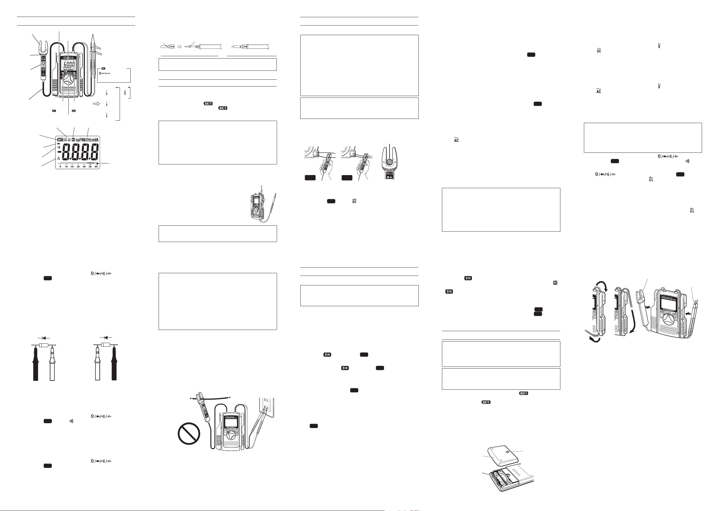
4.INSTRUMENT LAYOUT
Clamp Sensor:Pick up current flowing through the conductor.
Barrier:It is a part providing protection against electrical shock
an d en surin g th e mi nimum req uired air and cre ep age
distances.
A Zero Adjust Button:Used for zero adjustment on DCA. Also used
to reset the display resding.
Data Hold Button:Freezes the display reading.
Function Selector Switch:Selects function. Also used to
power the
instrument on.
Range Select or But ton:Select s meas uring mode. When t he
Ω range the d efaults to the Resistance . Then, press this
switch to cycle through Resistance → Diode → Cotinuity →
Cap acitor → R esistance. When the 60A, 120A r ange the
defaults to the AC. Then, press this switch to cycle through AC
→ DC → AC.
Test Lead Cap:Test leads can be used under the CAT.II and III
environme nts by at
taching a Prote ctive cap as illu strat ed
bel ow. Use of our Protective cap offer s d iffe rent len gths
suitable for the test environments.
#
CAUTION
● The Cap should be firmly attached to the Probes.
5.PREPARATIONS FOR MEASUREMENT
(1)Checking battery voltage
Set the Function Selector Switch to any position other than
the OFF position. If the marks on the display is clearly legible
without symbol "
" showing, battery voltage is OK.
If the display blanks or "
" is indicated, replace the
batteries according to section 8: Battery Replacement.
NOTE
● When the instrument is left powered on, the auto-power-save
function automatically shut the power off; The display blanks
even if the Function Selector Switch is set to a position other
than the OFF position in this state.
To power on the instrument, turn the Function Selector Switch
or press any Button. If the display still blanks, the batteries are
exhausted.
Replace the batteries.
(2) M
ake sure that the Function Selector Switch is set to the
appropriate range.
Also make sure that data hold function is not enabled. If
inappro pria te range is selected, desi red measurement
cannot be made.
(3) Permits the measurement by placing the
one test lead in the holster while confirming
the measurement value.
#
WARNING
● Verify proper operation on a known source before use or taking
action as a result of the indication of the instrument.
6-4 Diode Measurement
(1) Set the Function Selector Switch to "
".
(2) Press the
SEL
Button. "" mark is shown on the display.
(3) Connect the test leads to the circuit under test.
The measured value appears on the display.
[ Forward-bias Diode Test ]
Connect the red test lead to the anode and the black test
lead to the cathode.
[ Reverse-bias Diode Test ]
Connect the red test lead to the cathode and the black test
lead to the anode.
Note:◇ Hold the cla
mp sensor in the holster, while making the
diode measurement
6-5 Continuity Measurement
(1) Set the Function Selector Switch to "
".
(2) Press the
SEL
Button. " " mark is shown on the display.
(3) Connect the test leads to the circuit under test.
The measured value appears on the display.
When the measurement value is lower than 35±25Ω, the
instrument beeps.
Note:◇ Hold the clamp sensor in the holster, while making the
continuity measurement
6-6 Capacitor Measurement
(1) Set the Function Selector Switch to "
".
(2) Press the
SEL
Button. "F" mark is shown on the display.
(3) Connect the test leads to the circuit under test.
The measured value appears on the display.
Note:◇ Hold the clamp sensor in the holster, while making the
capacitor measurement.
6-7 Frequency Measurement
#
DANGER
● I n ord er to a vo id po ss ible shock hazar d, ne ve r ma ke
measurement on circuits with a maximum voltage difference
of 600V or grea ter bet ween conductors (300V or g reater
between a conductor and ground).
● D o not make measurement with the test leads connecte d
to the circuit under test. Never make measurement with the
battery compartment cover removed.
● D o not mak e current mea sur eme nt wit h the t
es t leads
connected to the circuit under test.
● K eep your fin ger s and h ands behin d the b arrier dur ing
measurement.
(1) Set the Function Selector Switch to "Hz."
(2) Measuring frequency of current:
A djust one o f t he conductors to the cente r o f the clamp
sensor's arrow.
Measured value is shown on the display.
Measuring frequency of voltage:
Connect the test leads to the circuit under
test. Measured
frequency is shown on the display.
Note:◇ Do not use both the clamp sensor and the test leads at
the same time, while making the frequency measurement.
◇ Hold the test leads in the holster, while making the frequency
measurement by using the clamp sensor.
◇ H old t he clamp sensor in the holster, whi le ma kin g the
frequency measurement by using the test leads.
7.OTHER FUNCTIONS
7-1 Auto-Power-Save Function
NOTE
● A small amount of current is consumed even in the power-save
state. Make sure to set the Function Selector Switch to the
OFF position when the instrument is not used.
This function helps to avoid unwanted exhaustion of the batteries
because of leaving the instrument powered on and extend battery
life.
The instrument automatically shifts to the power-save state about
15 minutes after the last F
unction Selector Switch or other switch
operation.
A minute before power-save mode the instrument beeps 5 times,
finally beeps longer and then shifts to the power-save mode.
To return to the normal state:
Press t he
Button or the
SEL
Button to return from the
power-save mode state to the normal state.
Note:◇ Pressing the
Button or the
SEL
Button over 2 sec
to return from the power-save mode state, the function of
each button is also enabled.
(ex.) When the function is 60A a nd in the power-save
mod e, press ing
SEL
Butt on over 2sec releases the
power-save mode and changes from initial AC mode to
DC mode.
To cancel the Auto-Power-Save Function
To cancel the Auto-Power-Save Function, turn the function
switch from OFF position to any other position with pressing
SEL
Button.
Note:◇ When the function switch is 60A or 120A, pressing A
ZERO ADJ Button over 2 sec enables to cancel the AutoPower-Save Function.
In this case, pressing A ZERO ADJ Button over 2 sec once
agin enables the Auto-Power-Save Function.
To enable the Auto-Power-Save Function once again
Turn the function switch to the OFF, and then to any position.
7-2 Data Hold Function
This is
a function to freeze a measured value on the display.
Press the
Button once to hold the current reading. In this
data hold state, the reading is held even if input varies. "
"
mark is shown on the LCD. To exit the data hold state, press the
Button again.
Note:◇ D at a Ho ld Fu nc tion is not ef fective whi le mak in g
Continuity or Diode measurement.
◇ When the function is on the position where
SEL
Button or
A ZERO ADJ Button is effective, pressing
SEL
Button or
A ZERO ADJ Button cancels the held indication.
8.BATTERY REPLACEMENT
#
WARNING
● In order to avoid possible shock hazard, always disconnect
the test leads from the circuit under test and set the Function
Selector Switch to the OFF position before trying to replace the
batteries.
#
CAUTION
●Do not mix new and old batteries.
● Install batteries in the orientation as shown inside the battery
compartment, observing correct polarity.
When the battery voltage warning mark "
" is shown on the
top left corner of the LCD, replace the batteries. Note that the
display blanks and "
" mark is not shown if the batteries are
completely exhausted.
(1) Set the Function Selector Switch to "OFF."
(2) Remove the instrument from the holster.
(3) Loosen the battery-compartment-cover-fixing screw on the
lower back of the instrument.
(4) Replace the batteries with two new R03 (UM-4) 1.5V batteries.
(5) Put the battery compartment cover back in place and tighten
the screw.
[ How to storage
the clamp sensor and the test leads ]
6.HOW TO MAKE MEASUREMENT
6-1 Current Measurement
#
DANGER
● I n ord er to avo id p os si ble sh ock ha zard, nev er mak e
measurement on circuits with a maximum voltage difference
of 600V or grea ter bet ween conductors (300V or g reater
between a conductor and ground).
● Do not make measurement with the test leads connected to
the circuit under test.
● Never make measurement with the battery compartment cover
removed.
● K eep your fin ger s and h ands behin d the b
ar rie r dur ing
measurement.
● To avoid electrical shock by touching the equipment under test
or its surroundings, be sure to wear insulated protective gear.
#
CAUTION
● When handling the clamp sensor, exercise caution not to apply
excessive shocks or vibration to the sensor.
●Maximum measurable conductor size is 12mm in diameter.
Note: ◇ Make sure that the test leads are in the holster while
making current measurement.
◇
Instrument can show the value over 120A, but the safe and
proper measurement range is limited lower than 120A.
6-1-1 DC Current Measurement
(1) The Function Selector Switch to the "60A" or "120A" position.
("AC" marks are shown on the top of the display.)
(2) Press the
SEL
Button. " " mark is shown on the display.
(3) P ress t he A ZERO A DJ Button to set t he reading o f the
instrument to zero.
(Incorrect zero adjustment makes measurement errors.)
(4) A djust one of the cond uctors to the center of the clamp
sensor's arrow.
( When the position of the conductor is not at the center of
the arrow, the error occurs.)
Measured value is shown on the display.
Note:◇ T he dire
ction of curre nt is plu s(+) w hen the cur rent
flows from the upside (A ZERO ADJ. Button side) to the
underside The direction is minus(-) when the current flows
from the underside to the upside.
◇ Minus "-" mark is shown at the left side of the value and
the bar graph while making minus current measurement.
◇ By changing the function switch 60A or 120A to the other
posi tion, the AC/DC mode is r
eset to the default (AC
mode). To set the DC mode, press the
SEL
Button again.
◇ T he zero adjustme nt is effective only for the current
measurement.
◇ After the zero adjustment the instrument operates as
follows.
(1) The bar graph disappears.
(2) The maximum counts is changed according to the
adjusted value.
(ex.)
The maximum count is 6039-100=5939, when
adjusted +100 counts to zero.
(3) △mark is shown on the display.
(4)
Pressing A ZERO ADJ. Button again or
SEL
Button,
or
changing the function switch releases zero adjustment
function when the zero adjustment is effective.
◇ Pressing the A ZERO ADJ button over 2 sec releases the
zero adjustment function.
6-1-2 AC Current Measurement
(1) Set the Function Selector Switch to "60A." or "120A".
("
" mark is shown on the top of the LCD.)
(2) A djust one of the cond uctors to the center of the clamp
sensor's arrow.
( When the position of the conductor is not at the center of
the arrow, the error occurs.)
Measured value is shown on the display.
Note:◇ Unlike DC current measurement, zero adjustment is not
necessary. There is not polarity indication either.
6-2 Voltage Measurement
#
DANGER
● I n ord er to avo id p os si ble sh ock ha zard, nev er mak e
measurement on circuits with a maximum voltage difference
of 600V or grea ter bet ween conductors (300V or g reater
between a conductor and ground).
● D o not make measurement with the battery compartment
cover removed.
● K eep your fin ger s and h ands behin d the b arrier dur ing
measurement.
Note:◇ Make sure that the clamp sensor is in the holster
while
making voltage measurement.
◇ I
nstrument may show the value over 600V, but the safe
and proper measurement range is limited lower than 600V.
6-2-1 DC Voltage Measurement
(1) Set the Function Selector Switch to "
".
("
" mark is shown on the LCD.)
(2) Short-circuit the tips of test leads to make the indication zero.
(3) Connect the red test lead to the positive (+) side of the circuit
under test and the black test lead to the negative (-) side.
Measured voltage value is shown on the display.
When the connection is reversed, "-" is shown on the display.
6-2-2 AC Voltage Measurement
(1) Set the Function Selector S
witch to " ".
("
" mark is shown on the LCD.)
(2) Connect the test leads to the circuit under test.
Measured voltage value is shown on the display.
Note:◇ The displayed value might be few digits instead of zero
even if shorting the test leads.
6-3 Resistance Measurement
#
DANGER
●Never make measurement on circuits that are live.
● Never make measurement with the battery compartment cover
removed.
● K eep your fin ger s and h ands behin d the b arrier dur ing
measurement.
(1) Set the Function Selector Switch to "
".
(2) Press the
SEL
Button and "Ω" mark is shown and " " mark
is not shown on the display (Resistance Measurement).
Immediately after setting t he Function Selector Switch to
"
", is not necessary to operate the
SEL
Button.
(3) Check that the display shows "
". Short the test leads and
check that the display reads about zero.
(4) Connect the test leads to the circuit under test. Measured
resistance value is shown on the display.
Note:◇
When the test leads are shorted, the display may read a small
resistance value. This is the resistance of the test leads.
◇ If there is an open in either of the test leads, " " is
shown on the display.
◇ The capacitive factor of the tested circuit may cause the
fluctuation of the measurement value, while making the
resistance measurement of high value .
◇ Make sure that the clamp sensor is in the holster while
making resistance measurement.
Adjust Button
Holster
Barrier
Clamp Sensor
LCD Display
Test Lead
Barrier
Function Selector Switch
Data Hold
Button
Range Selector
Button
A Zero
Continuity
Capacitor
Diode
Resistance
DC
AC
Clamp Sensor
Cable
Test Lead Cap
・・・・
Resistance
60A,120A
・・・・
AC
default setting
(
Button
)(
Button
)
Battery Voltage
AC / DC
Continuity
Data Hold
Bar Graph
Unit
Zero ADJ
Diode Test
Buzzer
Warning
Adjust a
conductor to
the center of
the arrow.
Correct
Incorrect
Conductor
Black Red
Forward-bias Diode T est
Test Lead
AnodeCathode
Red Black
Reverse-bias Diode Test
Test Lead
AnodeCathode
Prohibition
Battery
Compartment
Cover
Batteries
Screw
Wind the lead around the folder.
Test Leads
Clamp Sensor
ProtectiveCap
Exposedmetalpart
UncappedconditionforCAT.IIenvironment
CappedconditionforCAT.IIIenvironments
 Loading...