

Page 1
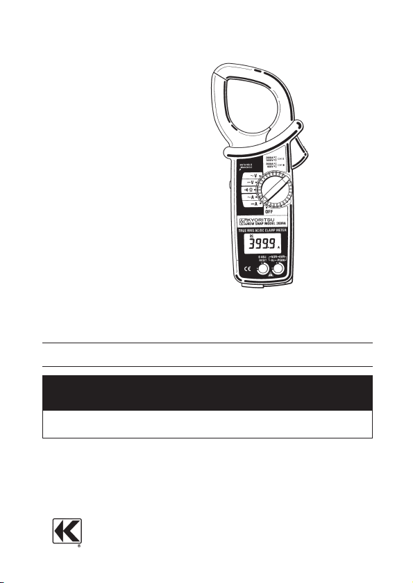
KEWSNAP
SERIES
KEWSNAP2009A
DIGITALCLAMPMETER
KYORITSUELECTRICALINSTRUMENTS
WORKS,LTD.
INSTRUCTIONMANUAL
Page 2

Contents
1.Safety Warnings ……………………………………………………… 1
2.Features ……………………………………………………………… 4
3.Specifications ………………………………………………………… 5
4.Instrument Layout …………………………………………………… 9
5.Preparation for Measurement ……………………………………… 12
5−1 Checking Battery Voltage …………………………………… 12
5−2 Checking Switch Setting and Operation ……………………12
6.Measurement ………………………………………………………… 13
6−1 DC Current Measurement ……………………………………13
6−2 AC Current Measurement ……………………………………14
6−3 DC Voltage Measurement ……………………………………15
6−4 AC Voltage Measurement ……………………………………16
6−5 Resistance Measurement …………………………………… 17
6−6 Continuity Check ………………………………………………18
6−7 Frequency Measurement …………………………………… 18
6−8 Peak Measurement ………………………………………… 19
6−9 Average Measurement ……………………………………… 21
7.Other Functions ……………………………………………………… 22
7−1 Sleep Function ……………………………………………… 22
7−2 Data Hold Function ……………………………………………22
7−3 LoHz Function …………………………………………………23
7−4 OUTPUT Terminal …………………………………………… 23
8.Battery Replacement ………………………………………………… 26
9.Optional Accessories …………………………………………………27
Page 3
―1―
1.SafetyWarnings
○
This instrument has been designed and tested according to IEC
Publication 61010: Safety Requirements for Electronic Measuring
Apparatus. This instruction manual contains warnings and safety
rules which must be observed by the user to ensure safe operation of
the instrument and retain it in safe condition. Therefore, read through
these operating instructions before starting using the instrument.
WARNING
●
Read through and understand instructions contained in this manual
before starting using the instrument.
●
Save and keep the manual handy to enable quick reference
whenever necessary.
●
Be sure to use the instrument only in its intended applications and
to follow measurement procedures described in the manual.
●
Be sure to understand and follow all safety instructions contained
in the manual.
Failure to follow the above instructions may cause injury, instrument
damage and/or damage to equipment under test.
○
The symbol indicated on the instrument means that the user
must refer to related parts in the manual for safe operation of the
instrument. Be sure to carefully read the instructions following
each symbol in this manual.
DANGER
is reserved for conditions and actions that are likely to
cause serious or fatal injury.
WARNING
is reserved for conditions and actions that can cause
serious or fatal injury.
CAUTION
is reserved for conditions and actions that can cause
minor injury or instrument damage.
Page 4
―2―
Followingsymbols are used on the instrumentand in theinstruction
manual.Attentionshouldbepaidtoeachsymboltoensureyoursafety.
Refertotheinstructionsinthemanual.
Thissymbolis marked where the user must refer tothe
instructionmanualso as not to cause personal injury or
instrumentdamage.
Indicatesaninstrumentwithdoubleorreinforcedinsulation.
Indicates that this instrument canclamp onbare conductors
whenmeasuring a voltage corresponding to theapplicable
Measurementcategory,whichismarkednexttothissymbol.
IndicatesAC(AlternatingCurrent).
IndicatesDC(DirectCurrent).
IndicatesACandDC.
DANGER
●
Never make measurement on a circuit above 750VAC/1000VDC.
●
Do not attempt to make measurement in the presence of flammable
gasses, fumes, vapor or dust. Otherwise, the use of the instrument
may cause sparking, which can lead to an explosion.
●
Never attempt to use the instrument if its surface or your hand is wet.
●
Do not exceed the maximum allowable input of any measurement range.
●
Never open the battery compartment cover when making measurement.
●
Never try to make measurement if any abnormal conditions, such
as broken Transformer jaws or case is noted.
●
The instrument is to be used only in its intended applications or
conditions. Otherwise, safety functions equipped with the
instrument doesn't work, and instrument damage or serious
personal injury may be caused.
WARNING
●N
ever attempt to make any measurement, if the instrument has any
structural abnormality such as cracked case and exposed metal part.
●
Do not turn the function selector switch with plugged in test leads
connected to the circuit under test.
●
Do not install substitute parts or make any modification to the
instrument. Return the instrument to Kyoritsu or your distributor for
repair or re-calibration.
●
Do not try to replace the battery if the surface of the instrument is wet.
●
Always switch off the instrument before opening the battery
compartment cover for battery replacement.
Page 5
―3―
CAUTION
●
Make sure that the function selector switch is set to an appropriate
position before making measurement.
●
Always make sure to insert each plug of the test leads fully into the
appropriate terminal on the instrument.
●
Make sure to remove the test leads from the instrument before
making current measurement.
●
Do not expose the instrument to the direct sun, extreme temperatures
or dew fall.
●
Be sure to set the function selector switch to the OFF" position
after use. When the instrument will not be in use for a long period
of time, place it in storage after removing the battery.
●
Use a damp cloth and detergent for cleaning the instrument. Do
not use abrasives or solvents.
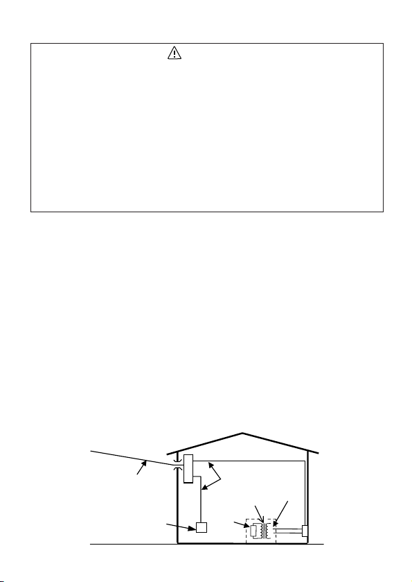
○
Measurement categories (Over-voltage categories)
To ensure safe operation of measuring instruments, IEC61010
establishes safety standards for various electrical environments,
categorized as CATⅠ to CATⅣ, and called measurement
categories. Higher-numbered categories correspond to electrical
environments with greater momentary energy, so a measuring
instrument designed for CATⅢ environments can endure greater
momentary energy than one designed for CATⅡ.
CAT Ⅰ : Secondary electrical circuits connected to an AC electrical
outlet through a transformer or similar device.
CAT Ⅱ : Primary electrical circuits of equipment connected to an
AC electrical outlet by a power cord.
CAT Ⅲ : Primary electrical circuits of the equipment connected
directly to the distribution panel, and feeders from the
distribution panel to outlets.
CAT Ⅳ :The circuit from the service drop to the service entrance,
and to the power meter and primary over-current
protection device (distribution panel).
S
Incoming wire
CAT.IV
ocket
Interior wiring
CAT.III
Transformer
CAT.I
CAT.II
Page 6

―4―
●Tear-drop-shaped jaws for ease of use in crowded cable areas and
other tight places.
●Accurate true-RMS reading of AC current or voltage with distorted
waveform.
●LoHz mode automatically adjusts sample rate for easy reading of low
frequency AC current or voltage.
●Average function for easy reading of input with large variation.
●Auto-null function for easy zero adjustment.
●Provides frequency reading in AC current or voltage measurement.
●Auto-ranging feature on current, voltage and resistance ranges.
●Wide measuring range from 0 up to 2000A.
●Terminal cover to avoid the use of an incorrect terminal.
●PEAK function for measuring a peak of input
●Provides recorder output for long hour monitoring
●Data Hold function for easy reading in dimly light or hard-to-read
locations
●Sleep feature to extend battery life.
●Permits easy continuity check with a beeper
●Provides a dynamic range of 4,000 counts full scale
●Wide frequency range from 30Hz to 1kHz
●Uses shrouded transformer jaws to further improve safety
●Designed to CAT.Ⅲ 600VAC,DC / CAT.Ⅱ750VAC,1000VDC pollution
degree2 specified by the international safety standard:IEC61010.
2.Features
Page 7
―5―
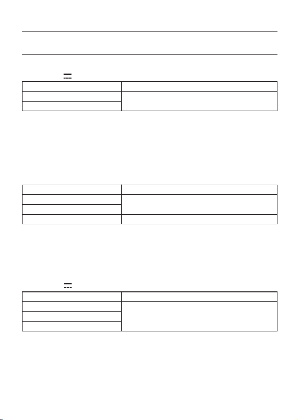
3.Specifications
Measuring Ranges and Accuracy (at 23±5℃, 45-75% relative humidity)
DC Current A
Auto-ranging (Defaults to Lo):
Lo:0-399.9A (Shifts to Hi at 400.0A)
Hi:150-2000A
(Shifts to Lo at 149A. At 2020A or above,"OL" is shown.)
AC Current 〜A (Crest factor(CF): 3.0 or less, peak current: 3000A or less)
Auto-ranging (Defaults to Lo) :
Lo:0-399.9A (Shifts to Hi at 400.0A)
Hi:150-2000A (Shifts to Lo at 149A. At 2020A or above, "OL" is shown.)
DC Voltage V (Input impedance: 2MΩ)
Auto-ranging (Defaults to Lo):
Lo:0-39.99V (Shifts to Mid at 40.00 V)
Mid:15.0-399.9V (Shifts to Lo at 14.9V and to Hi at 400.0V)
Hi:150-1000A
(Shifts to Mid at 149V. At 1020V or above, OL" is shown.)
Measuring Range (Auto-ranging)
0〜±399.9A
±150〜±2000A
Accuracy
±1.5%rdg±2dgt
Measuring Range (Auto-ranging)
0〜399.9A
150〜1700A
1701〜2000A
Accuracy
±1.5%rdg±3dgt(50/60Hz)
±3.0%rdg±4dgt(30〜1kHz)
±3.5%rdg±3dgt(50/60Hz)
Measuring Range (Auto-ranging)
0〜±39.99V
±15.0〜±399.9V
±150〜±1000V
Accuracy
±1.0%rdg±2dgt
Page 8
―6―
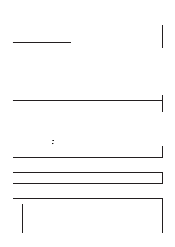
AC Voltage 〜V
(Crest factor(CF): 3.0 or less, peak voltage: 1200V or less)
Auto-ranging (Defaults to Lo):
Lo:0-39.99V (Shifts to Mid at 40.00V)
Mid:15.0-399.9V (Shifts to Lo at 14.9 and to Hi at 400.0V)
Hi:150-750V
(Shifts to Mid at 149V. At 770V or above,OL" is shown.)
Resistance Ω
Auto-ranging (Defaults to Lo):
Lo:0-399.9Ω (Shifts to Hi at 400.0Ω)
Hi:150-3999Ω
(Shifts to Lo at 149Ω. At 4000Ω or above, OL" is shown.)
Continuity Check Ω (Range fixed)
Frequency
OUTPUT(Output impedance: about 10kΩ)
Measuring Range (Auto-ranging)
0〜39.99V
15.0〜399.9V
150〜750V
Accuracy
±1.5%rdg±3dgt(50/60Hz)
±2.0%rdg±4dgt(30〜1kHz)
Measuring Range (Auto-ranging)
0〜399.9Ω
150〜3999Ω
Accuracy
±1.5%rdg±2dgt
Measuring Range
10〜399.9Ω
Accuracy
±1.5%rdg±2dgt
Measuring Range
0〜±399.9A
±150〜±2000A
0〜399.9A
150〜1700A
1701〜2000A
Output Voltage(mVDC)
0〜±399.9mV
±15.0〜±200.0mV
0〜399.9mV
15.0〜170.0mV
170.1〜200.0mV
DC
AC
Accuracy
±1.5%rdg±3mV
±1.5%rdg±3mV(50/60Hz)
±3.0%rdg±3mV(40〜1kHz)
±3.5%rdg±3mV(50/60Hz)
Measuring Range
10〜3999Hz
Accuracy
±1.5%rdg±5dgt
Page 9

―7―
●Operating System Dual Integration
●Display Liquid crystal display with a maximum
count of 4000 plus annunciators
●Overrange Indication "OL" is shown on the display
●Response Time Approx. 2 seconds.
●Sample Rate About 3 times per second.
●Location for use Indoor use, Altitude up to 2000m
●
Temperature and Humidity
23 +/-5℃, relative humidity up to 75%
for Guranteed Accuracy without condensation
●Operating Temperature 0-40℃, relative humidity up to 85%
and Humidity without condensation
●Storage Temperature -20-60℃, relative humidity up to 85%
and Humidity without condensation
●Power Source 6F22(DC9V) or equivalent battery
●Current Consumption Approx. 15mA max.
●Sleep function Automatically powered down in about 30
minutes after the last switch operation
(power consumption: about 200μA)
●Overload Protection
DC/AC current ranges: 2400A AC for 10sec
DC/AC voltage ranges: 1200V AC/DC for 10sec
Resistance range: 600V AC/DC for 10sec
●Withstand Voltage 5500V AC, 50/60Hz for 1 minute
between electrical circuit and housing
case or metal part of the jaws
●Insulation Resistance 10 MΩ or greater at 1000V between
electrical circuit and housing case or
metal part of the jaws
●Conductor Size Approx. 55㎜ diameter max.
●Dimensions 250(L)x105(W)x49(D)mm
●Weight About 530g
●Accessories Test leads M-7017
6F22 battery
Carrying case M-9094
Instruction manual
Recorder output Plug M-8201
●Optional Accessories Multi-Tran M-8008
Recorder M-5100A, etc.
Output Lead M-7014.
Page 10
―8―
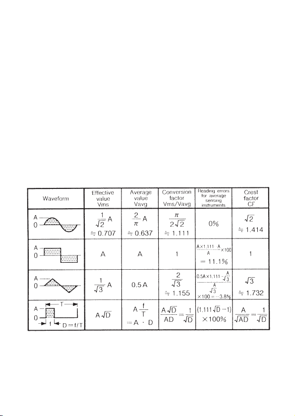
*EffectiveValue(RMS)
Most alternating currents and voltages are expressed in effective
values, which are also referred to as RMS (Root-Mean-Square) values.
The effective value is the square root of the average of square of
alternating current or voltage values.
Many clamp meters using a conventional rectifying circuit have "RMS"
scales for AC measurement. The scales are, however, actually
calibrated in terms of the effective value of a sine wave though the
clamp meter is responding to the average value. The calibration is
done with a conversion factor of 1.111 for sine wave, which is found by
dividing the effective value by the average value. These instruments
are therefore in error if the input voltage or current has some other
shape than sine wave.
*
CF (Crest Factor) is found by dividing the peak value by the effective value.
Examples:
DC: CF =1
Sine wave: CF=1.414
Square wave with a 1: 10 duty ratio: CF=3
Page 11

―9―
4.InstrumentLayout
①Transformer Jaws
Pick up current flowing through the conductor.
②Jaw Trigger
Operates the transformer jaws. Press to open the Transformer Jaws.
③Function Selector Switch
Selects function. Also used to power the instrument on.
④Data Hold Button
Freezes the display reading. "H" is shown on the display when Data
Hold is enabled.
︸
①
②
③
④
⑦
⑤
⑥
⑫
⑭
⑪
⑨
⑧
⑩
⑬
⑮
Page 12

―10―
DataHold
Resistance
Voltage
Ampere
Lowfrequencyinput
DCAautozero
Peakmode
Lowbatterywarning
ContinuityCheck
Negativesign
AC
DC
Averagemode
When the plug is inserted into the output terminal, Data Hold Switch
operates as range selection switch.(See 7-4 output terminal)
⑤Mode Selector Button
Selects measuring mode. The instrument defaults to the normal
mode (NOR). Then, press this switch to cycle through measuring
modes. In any mode, pressing this switch for more than one second
returns the instrument to the normal mode.
⑥Zero Adjust/Reset Button
Used for zero adjustment on DCA and resistance ranges. Also used
to reset the display reading in the PEAK mode. On DCA range,
"AUTO" is shown on the display when auto-zeroing is completed.
(Auto-zeroing is available on 400A range only.)
⑦Digital Display
Field effect digital display with maximum reading of 3999. Function
symbols and decimal point are controlled by the microprocessor
based on the selected function and measuring mode.
Page 13

―11―
⑧Terminal Cover
Slides over V/Ω and COM Terminals to prevent access to them when
OUTPUT terminal is in use.
⑨OUTPUT Terminal(For AC or DC current range only)
Provides DC voltage output in proportion to the AC or DC current
reading. The output is connected to a recording device such as a
chart recorder for long hour monitoring. No output is available on
voltage and resistance ranges.
⑩COM Terminal
Accepts the black test lead for voltage or resistance measurement.
⑪V/Ω Terminal
Accepts the red test lead for voltage or resistance measurement.
⑫Safety Hand Strap
Prevents the instrument from slipping off the hand during use.
⑬ Test Leads (Model 7107)
Connected to COM and V/Ω terminals for voltage or resistance
measurement.
⑭Output Plug(Model 8201)
Plugs into the OUTPUT terminal for connection to a recording device.
(See section 7ー4, OUTPUT Terminal.)
⑮Barrier
It is a part providing protection against electrical shock and ensuring
the minimum required air and creepage distances.
Page 14

―12―
5.PreparationforMeasurement
5−1 CheckingBatteryVoltage
①Set the function selector switch to any position other than "OFF".
②When the display is clear without "BATT" showing, proceed to
measurement.
③When the display blanks or "BATT" is indicated, replace the battery
according to section 8. Battery Replacement.
NOTE
● The Sleep feature automatically turns the instrument off in about
30 minutes after the last switch or button operation. Therefore, the
display may be blank even with the function selector switch set to
a position other than "OFF". To operate the instrument in this
case, turn the switch back to the "OFF" position, then to any other
position, or press any button.
5−2 CheckingSwitchSettingandOperation
Make sure that the function selector switch is set to the correct
position, the instrument is set to the correct measuring mode and the
Data Hold function is disabled. Otherwise, desired measurement
cannot be made. (See section 6 for measurement instructions and
section 7 for notes on functions.)
Page 15

―13―
6.Measurement
6−1 DCCurrentMeasurement
DANGER
●Do not make measurement on a circuit above 1000VDC. This may
cause shock hazard or damage to the instrument or equipment under
test.
●
Do not make measurement with the battery compartment cover
removed from the instrument.
●Do not make current measurement with the test leads connected to the
V/Ω and COM terminals.
●Keep your fingers and hands behind the barrier during measurement.
①Set the function selector switch to the " A" position. DC" should
be shown on the upper left corner of the display.
②With the transformer jaws closed and without clamping them onto
the conductor, press the Zero Adjust/Reset button for about one
second to zero adjust the display. (Zero adjust feature is for 400A
range only.) When zero adjustment is completed, "AUTO" appears
on the display.
③Press the trigger to open the transformer jaws and clamp them onto
the conductor under test, then take the reading on the display. The
most accurate reading will be obtained by keeping the conductor at
the center of the transformer jaws.
Correct
Wrong
Page 16

―14―
NOTE
● During current measurement, keep the transformer jaws fully
closed. Otherwise, accurate measurement cannot be made. The
maximum measurable conductor size is approx. 55mm in
diameter.
● When the current flows from the upside (the display side) to the
underside of the instrument, the reading is indicated positive.
● The Zero Adjust/Reset button may not completely zero adjust the
output voltage from the OUTPUT terminal. In this case, make zero
adjustment on the recording device.
● Turing the function selector switch to a position other than DCA
cancels the zero adjustment .
6−2 ACCurrentMeasurement
DANGER
●
Never use the instrument on a circuit above 750VAC. This may
cause electrical shock hazard and damage to the instrument or the
circuit under test.
●Do not make measurement with the test leads plugged into the
instrument.
●
Do not make measurement with the battery compartment cover
removed.
●Keep your fingers and hands behind the barrier during measurement.
Correct
Wrong
Page 17

―15―
①Set the function selector switch to the "〜A" position. AC" should
be shown on the upper left corner of the display.
②Press the trigger to open the transformer jaws and clamp them onto
a single conductor and take the reading on the display. The most
accurate reading will be obtained by keeping the conductor at the
center of the transformer jaws.
NOTE
● During current measurement, keep the transformer jaws fully
closed. Otherwise, accurate measurements cannot be taken.
Maximum conductor size is 55㎜ in diameter.
● Zero adjustment is not necessary in AC current measurement.
● When the current under test measures 3% of the full scale or less,
or the frequency of the current is low, "LoHz" is indicated on the
display.
6−3 DCVoltageMeasurement
DANGER
●Never use the instrument on a circuit above 1000VDC. This may
cause electrical shock hazard and damage to the instrument or the
circuit under test.
●Do not make measurement with the battery compartment cover
removed.
●Keep your fingers and hands behind the barrier during measurement.
Page 18

―16―
①Set the function selector switch to the " V" position. DC" should
be shown on the upper left corner of the display.
②Slide the terminal cover to the left to disclose the V/Ω and COM
terminals. Plug the red test lead into the V/Ω terminal and the black
test lead into COM terminal.
③Connect the tip of the red and black test leads to the positive (+) and
negative (-) sides of the circuit under test respectively. Take the
reading on the display. If the connection is reversed, the display
indicates the "-" sign.
6−4 ACVoltageMeasurements
DANGER
●Never use the instrument on a circuit above 750VAC. This may
cause electrical shock hazard and damage to the instrument or the
circuit under test.
●Do not make measurement with the battery compartment cover
removed.
●Keep your fingers and hands behind the barrier during measurement.
①Set the function selector switch to the "〜V" position. "AC" should
be shown on the upper left corner of the display.
②Slide the terminal cover to the left to disclose the V/Ω and COM
terminals. Plug the red test lead into V/Ω terminal and the black test
lead into the COM terminal.
Black
testlead
Redtestlead
Page 19

―17―
③Connect the tip of the red and black test leads to the circuit under test
and take the reading on the display.
NOTE
● When the voltage under test measures 3% of the full scale or less,
or the frequency of the voltage is low, "LoHz" is indicated on the
display.
6−5 ResistanceMeasurement
DANGER
●Never use the instrument on an energized circuit.
●Do not make measurement with the battery compartment cover
removed.
●Keep your fingers and hands behind the barrier during measurement.
①Set the function selector switch to the " Ω" position.
②Slide the terminal cover to the left to disclose the V/Ω and COM
terminals. Plug the red test lead into the V/Ω terminal and the black
test lead into the COM terminal.
③With the tip of the test leads shorted together, press the Zero
Adjust/Reset button to offset the resistance of the test leads.
④Connect the tip of the test leads to the circuit under test and take the
reading on the display.
Page 20

―18―
6−6 ContinuityCheck(400Ω rangefixed)
※
The continuity check mode is enabled by pressing the mode selector
switch on resistance range. " " is indicated on the display to show
the instrument in the continuity check mode. The buzzer beeps, if the
resistance under test is 20.0Ωor less.
DANGER
●Never use the instrument on an energized circuit.
●Do not make measurement with the battery compartment cover
removed.
●Keep your fingers and hands behind the barrier during measurement.
①Set the function selector switch to the " Ω" position.
②Slide the terminal cover to the left to disclose the V/Ω and COM
terminals. Plug the red test lead into the V/Ω terminal and the black
test lead into the COM terminal.
③With the tip of the test leads shorted together, press the Zero
Adjust/Reset button to offset the resistance of the test leads.
④Press the mode selector button once to enter from the normal mode
to the continuity check mode. " " should be indicated on the
display.
⑤Connect the tip of the test leads to the circuit under test. If the
resistance is 20.0Ω or less, the buzzer beeps.
6−7 FrequencyMeasurement
●
On ACA or ACV range, the frequency of the current or voltage under
test can be counted and shown on the display.
●
In the frequency measurement mode, "Hz" is indicated on the display.
●
Trigger threshold is approx. 10V for AC voltage and approx. 10A for AC
current. At frequency measurement, in case of low input signal, it often
happens that measurement cannot be made. Because range is fixed at
400V for AC voltage and at 400A for AC current.
Page 21

―19―
DANGER
●Never use the instrument on a high voltage circuit above 750VAC.
This may cause electrical shock hazard and damage to the
instrument or the circuit under test.
●Do not make measurement with the battery compartment cover
removed.
●Do not make current measurement with the test leads plugged into the
instrument.
●Keep your fingers and hands behind the barrier during measurement.
①Set the function selector switch to the "〜A" or "〜V" position.
②Press the mode selector button three times to enter from the normal
mode to the frequency measurement mode. "Hz" should be indicated
on the display.
③Follow instructions for ACA or ACV measurement and take the
frequency reading.
NOTE
● When the voltage under test measures 3% of the full scale or less,
or the frequency of the current or voltage is 40Hz or less, "LoHz" is
indicated on the display.
6−8 PeakMeasurement
●
In the PEAK mode, the display shows current or voltage's crest in
effective value. (For example, when the current or voltage is sinusoidal,
the reading equals the crest value divided by the square root of two.)
The display reading is constantly updated with a maximum crest.
●
In this mode, "PEAK" is indicated on the display.
●
Response time is 300ms in DC measurement and 10ms in AC
measurement.
Page 22

―20―
DANGER
●Never use the instrument on a circuit above 750VAC/1000VDC.
This may cause electrical shock hazard and damage to the
instrument or the circuit under test.
●Do not make measurement with the battery compartment cover
removed.
●Do not make measurement with the test leads plugged into the
instrument.
●Keep your fingers and hands behind the barrier during measurement.
①The PEAK mode is available on DCA, ACA, DCV and DCA ranges.
Set the function selector switch to the desired position.
Note:Only on DCA range, press the Zero Adjust/Reset button for
about one second to zero adjust the reading with the
transformer jaws closed.
②Press the mode selector button twice to enter from the normal mode
to the PEAK mode. "PEAK" should be shown on the display.
③Follow instructions for DCA, ACA, DCV or ACV measurement.
Note:For accurate reading, press the Zero Adjust/Reset button to reset
the reading after clamping onto the conductor or making test lead
connections to the circuit under test. Then, proceed to
measurement.
Vp
INPUTCurrent
Vp/
2
PeakHold
Page 23

―21―
NOTE
● In the PEAK mode, the auto-ranging feature is disabled and
measuring ranges are fixed as follows.
DC/ACA: 0-400.0A
DC/ACV: 0-400.0A
● The Sleep function is disabled in the PEAK mode as well.
6−9 AverageMeasurement
●
In the Average mode, "AVG" is indicated on the display.
●
The display reads a running average of six readings over an interval of
about 2 seconds.
●
This mode is available on ACV, DCV, ACA and DCA ranges.
①Set the function selector switch to the desired position.
②Press the mode selector button once to enter from the normal mode
to the Average mode. "AVG" should be indicated on the display.
③Follow instructions for ACV, DCV, ACA or DCA measurement.
④The display shows a running average of six readings over an interval
of about 2 seconds.
Page 24

―22―
7−1 SleepFunction
CAUTION
●The instrument consumes small amount of battery power in the
sleep mode. Make sure to set the function selector switch to the
OFF position after use.
This is a function to prevent the instrument from being left powered
on in order to conserve battery life. This function causes the
instrument to enter the Sleep (powered-down) mode about 30
minutes after the last switch or button operation.
To exit the Sleep mode, turn the function selector switch back to
"OFF", then to any other position, or press any button.
NOTE
● Connecting the plug to the OUTPUT terminal disables the Sleep
function. The function is enabled on removing the plug from the
terminal.
● The Sleep function is disabled in the PEAK measurement mode.
7−2 DataHoldFunction
This is a function used to freeze the measured value on the display.
Press the Data Hold button to freeze the reading. The reading will be
held regardless of subsequent variation in input. "H" is shown on the
upper right corner of the display while the instrument is in the Data
Hold mode.
To exit the Data Hold mode, press the Data Hold button again.
7.OtherFunctions
Page 25

―23―
NOTE
● If the instrument in the Data Hold mode goes into "sleep," it will
return to the normal mode.
7−3 LoHzFunction
In ACV or ACA range, if frequency of the voltage or current under test
is 40Hz or lower, the display indicates "LoHz" and sample rate is
automatically switched from the normal 3 times/sec to 2 times/sec to
reduce fluctuation of the reading.
"LoHz" is also indicated where input is 3% of full scale or less.
7−4 OUTPUTTerminal(Forcurrentrangesonly)
DANGER
●Never use the instrument on a circuit above 750VAC/1000VDC.
This may cause electrical shock hazard and damage to the
instrument or the circuit under test.
●Do not make measurement with the battery compartment cover
removed.
●Never apply voltage to the OUTPUT terminal.
①Attach the output plug to a connection lead so that the output
voltage can be connected to a recording device such as a chart
recorder.
Page 26

―24―
②Slide the terminal cover to the right to disclose the OUTPUT terminal
and insert the output plug into the terminal. Make connection to the
recording device.
③When the plug is inserted into the output terminal, auto-range function
is cleared.
Set the range depending on the state of Data Hold Switch.
Data Hold Switch OFF 400A range
Data Hold Switch ON 2000A range
Note:After measurement, be sure to return Data Hold Switch to OFF
position.
④Set the function selector switch to the desired position (ACA or DCA)
and follow appropriate measurement instructions.
NOTE
● During current measurement, keep the transformer jaws fully
closed. Otherwise, accurate measurement cannot be made. The
maximum measurable conductor size is approx. 55mm in
diameter.
● Zero adjustment is not necessary on AC current range.
● On DC current range, the Zero Adjust/Reset button may not
completely zero adjust the output voltage from the OUTPUT
terminal. In this case, make zero adjustment on the recording
device.
● Connecting the plug to the OUTPUT terminal disables the Sleep
function. The function is enabled on removing the plug from the
terminal.
Page 27

―25―
● Consult the output voltage specifications shown in section 3 and
adjust the sensitivity of the recording device.
● For long hours of use of the OUTPUT terminal, use an Alkaline
battery, which will extend continuous recording time up to about 24
hours.
Page 28

―26―
WARNING
●To avoid electric shock hazard, make sure to set the function selector
switch to "OFF" and remove the test leads from the instrument before
trying to replace battery.
CAUTION
●Do not mix new and old battery.
●Make sure to install battery in correct polarity as indicated in the
battery compartment.
If the battery voltage becomes too low for the instrument to operate
normally, "BATT" is shown on the display. Then, replace the battery.
Note that when the battery is completely exhausted, the display
blanks without "BATT" shown.
①Set the function selector switch to the "OFF" position.
②
Unscrew and remove the battery compartment on the bottom of the
instrument.
③Replace the battery observing correct polarity. Use a new 6F22 or
equivalent battery.
④Re-place and screw the battery compartment cover.
8.BatteryReplacement
Screw
Battery
Batterycompartmentcover
Page 29

―27―
9.OptionalAccessories
● MODEL 8008 (For AC current measurement only)
Multi-Tran Model 8008 is designed to increase the measuring
capability of a clamp meter. With the use of the Multi-tran, you can
not only extend current range over 3000A, but also clamp on a
large bus-bar or conductor.
①Set the function selector switch to the "〜A" position .
②As shown in the figure below, clamp KEW SNAP 2009A onto the
pickup coil of MODEL 8008.
③Clamp MODEL 8008 onto the bus-bar or conductor under test.
④Take the reading on KEW SNAP 2009A and multiply it by 10.
Page 30

―28―
MEMO
Page 31

―29―
MEMO
Page 32

DISTRIBUTOR
92―1394C
06-05
Kyoritsu reserves the rights to change specifications or
designs described in this manual without notice and without
obligations.
 Loading...