

Page 1
取扱説明書
INSTRUCTIONMANUAL
KEWSNAP
SERIES
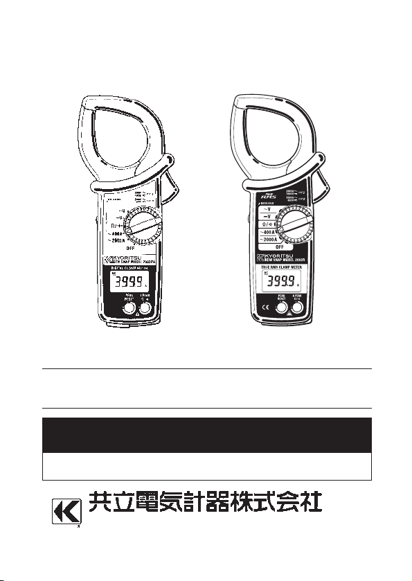
MODEL 2002PA 2002R
デジタルクランプメータ
DIGITALCLAMPMETER
KYORITSUELECTRICALINSTRUMENTS
WORKS,LTD.
Page 2

―25―
Contents
ENGLISH
1.Safety Warnings ……………………………………………………… 26
2.Features ……………………………………………………………… 28
3.Specifications
3−1 MODEL 2002PA…………………………………………………29
3−2 MODEL 2002R ………………………………………………… 31
4.Instrument Layout …………………………………………………… 34
5.Preparation for Measurement
5−1 Battery Voltage Check ……………………………………… 35
5−2 Checking Switch Setting and Operation ……………………35
6.Measurement
6−1 Current Measurement…………………………………………36
6−2 Voltage Measurement ……………………………………… 38
6−3 Resistance Measurement …………………………………… 39
7.Notes on Functions
7−1 Data Hold ………………………………………………………41
7−2 Sleep Function…………………………………………………41
7−3 Output for Recorder …………………………………………42
7−4 Mode Switching Function ……………………………………43
8.Battery Replacement ………………………………………………… 44
9.Optional Accessories …………………………………………………45
Page 3
―26―
1.SafetyWarnings
○This instrument has been designed and tested according to IEC
Publication 61010;Safety Requirements for Electronic Measuring
Apparatus. This instruction manual contains warnings and safety
rules which must be observed by the user to ensure safe operation of
the instrument and to retain it in safe condition. Therefore, read
through these operating instructions before starting using the
instrument.
WARNING
●Read through and understand instructions contained in this manual
before starting to use the instrument.
●Save and keep the manual handy to enable quick reference
whenever necessary.
●Be sure to use the instrument only in its intended applications and
to follow measurement procedures described in the manual.
●Be sure to understand and follow all safety instructions contained
in the manual.
Be sure to observe the above instructions.
Failure to follow the above instructions may cause injury, instrument
damage and/or damage to equipment under test.
○The symbol indicated on the instrument means that the user
must refer to related parts in the manual for safe operation of the
instrument. Be sure to carefully read the instructions following
each symbol in this manual.
DANGER is reserved for conditions and actions that are likely to
cause serious or fatal injury.
WARNING is reserved for conditions and actions that can cause
serious or fatal injury.
CAUTION is reserved for conditions and actions that can cause
minor injury or instrument damage.
Page 4
―27―
DANGER
●Never make measurement on the circuit above 750VAC or 1000VDC.
●Do not attempt to make measurement in the presence of flammable
gasses, fumes, vapor or dust. Otherwise, the use of the instrument
may cause sparking, which can lead to an explosion.
●Transformer jaw tips are designed not to short the circuit under
test. If equipment under test has exposed conductive parts,
however, extra precaution should be taken to minimize the
possibility of shorting.
●Never attempt to use the instrument if its surface or your hand is wet.
●Do not exceed the maximum allowable input of any measurement
range.
●Never open the battery compartment cover and the instrument case
when making measurement.
●Verify proper operation on a known source before use or taking
action as a result of the indication of the instrument.
WARNING
●Never attempt to make any measurement if any abnormal conditions
are noted, such as broken case, cracked test leads and exposed
metal parts.
●Do not turn the function selector switch with test leads connected to
the instrument.
●Do not install substitute parts or make any modification to the
instrument. Return the instrument to your distributor for repair or recalibration.
●Do not try to replace the batteries if the surface of the instrument is wet.
●Always switch off the instrument and make sure to disconnect test leads
before opening the battery compartment cover for battery replacement.
CAUTION
●Always make sure to check the function selector switch is set to an
appropriate position before starting measurement.
●Always make sure to insert the plug of each lead fully into the
appropriate terminal on the instrument.
●Be sure to set the function selector switch to the "OFF" position
after use. When the instrument will not be in use for a long period,
place it in storage after removing the batteries.
●Do not expose the instrument to the direct sun, high temperature or
dew fall.
●Use a cloth dipped in water or neutral detergent for cleaning the
instrument. Do not use abrasives or solvents.
Page 5

―28―
●Tear-drop-shaped jaws for ease of use in crowded cable areas and
other tight places.
●Accurate true-RMS reading of AC current or voltage with distorted
waveform (MODEL2002R)
●Provides a wide measuring range from 0 up to 2000A.
●Terminal cover to avoid the use of an incorrect terminal.
●Measures current variation as short as 10 msec with peak-hold
feature.
●Provides output to a chart recorder for current variation recording.
●Designed to international safety standards.
IEC61010-1 (CAT.Ⅲ 600V /CAT.Ⅱ 1000V Pollution degree 2)
IEC61010-031, IEC61010-2-032
●Data hold function to allow easy readings in dimly lit or hard-to-read
locations.
●Sleep feature to conserve battery power.
●Permits easy continuity check with a beeper.
●Provides a dynamic range of 4,000 counts full scale.
●Provides wide measuring range of voltage and resistance in auto-
ranging.
●Wide frequency range from 40Hz to 1kHz (Current measuring range:
0-1500A).
●Transformer jows fitted with guard to further improve safety.
●Protected throughout by double or reinforced insulationF.
2.Features
Page 6
―29―
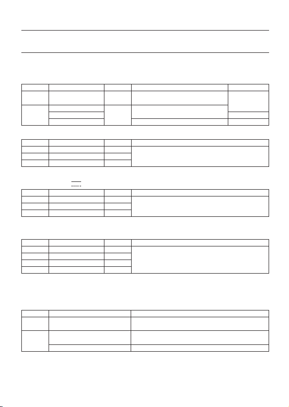
3−1 MODEL2002PA
●Measuring Ranges and Accuracy(at 23±5℃, relative humidity 45-75%)
AC Current 〜400A,〜2000A
3.Specifications
Range
400A
2000A
Measuring Range
0〜400.0A
0〜1000A
1000〜1500A
1500〜2000A
Measuring Range
0〜40.00V
15.0〜400.0V
150〜750V
Measuring Range
0〜±40.00V
±15.0〜±400.0V
±150〜±1000V
Measuring Range
0〜400.0Ω
0.150〜4.000kΩ
1.50〜40.00kΩ
15.0〜400.0kΩ
Output Voltage/Measuring Range
0〜400.0mV /0〜400A
0〜150.0mV /0〜1500A
150.0〜200.0mV/1500〜2000A
Resolution
0.1A
1A
Resolution
0.01V
0.1V
1V
Resolution
0.01V
0.1V
1V
Resolution
0.1Ω
1Ω
10Ω
100Ω
Accuracy(Frequency Range)
±1.0%rdg±3dgt(50/60Hz)
±2.0%rdg±3dgt(40〜1kHz)
±1.0%rdg±3dgt(50/60Hz)
±3.0%rdg±3dgt(40〜1kHz)
±3.0%rdg (50/60Hz)
Accuracy(Frequency Range)
±1.0%rdg±2dgt(50/60Hz)
±1.5%rdg±3dgt(40〜1kHz)
Accuracy
±1.0%rdg±2dgt
Accuracy
±1.5%rdg±2dgt
Accuracy(Frequency Range)
±1.5%rdg±0.5mV(50/60Hz)
±2.5%rdg±0.5mV(40〜1kHz)
±1.5%rdg±0.5mV(50/60Hz)
±3.5%rdg±0.5mV(40〜1kHz)
±3.5%rdg (50/60Hz)
Maximum Measurement Time
Continuous
15min
5min
Range
40V
400V
750V
Range
40V
400V
1000V
Range
400Ω
4kΩ
40kΩ
400kΩ
Range
400A
2000A
AC Voltage(〜V)Auto-ranging
Initially set to the 40V range. Input impedance is about 1MΩ.
DC Voltage(V)Auto-ranging
Initially set to the 40V range. Input impedance is about 1MΩ.
Resistance(Auto-ranging)
Initially set to the 400Ω range. In the continuity check mode, fixed to the 400Ω range and
when the reading is not more than 50±35Ω, the buzzer beeps.
OUTPUT(AC Current Ranges)
DC Output: 100.0mV per 1000 counts (Output impedance: about 10kΩ)
●
Electromagnetic compatibility (EMC)
EN61000-4-3 Radiated RF electromagnetic field immunity
RF field strength
=
<
=1V/m
, total accuracy:specified accuracy
RF field strength
=3V/m
, total accuracy:specified accuracy
+2%
of range
Page 7

―30―
●Operating System Dual Integration
●Display Liquid crystal display with a maximum
count of 4000
●Low Battery Warning "BATT" symbol is displayed on the digital
display.
●Overrange Indication "OL" is displayed where input exceeds
the upper limit of a range
●Response Time Approx. 2 seconds
●Sleep function Automatically powered down in about 10
minutes after the last switch operation
●Data Hold Available in all ranges provided the peak
measurement mode is deactivated.
●Operating Environmental indoor use
conditions altitude up to 2000m
●Storage Temperature ー20〜60℃, relative humidity up to 85%
and Humidity without condensation
●Operating Temperature 0〜40℃, relative humidity up to 85%
and Humidity without condensation
●Conductor Size Approx. 54.5㎜ diameter max.
●Overload Protection 2400A AC for 10sec
1200V AC/DC for 10sec
600V AC for 10sec
●Withstand Voltage 5320V AC for 5 seconds between electrical
circuit and housing cases or metal parts
of jaws
●Insulation Resistance 10MΩ or greater at 1000V between
electrical circuit and housing cases or
metal parts of jaws
●Safety Standard IEC 61010-1: Measurement CAT.Ⅲ
600V/CAT.Ⅱ1000V, pollution degree 2.
●Dimensions 247(L)×105(W)×49(D)mm
●Weight Approx. 470g(battery included)
●Power Source Two R6P(DC1.5V) batteries or equivalent
●Current Consumption Approx. 5mA max. (Approx. 20μA in the
sleep mode)
●Accessories Test leads M-7107
Two R6P batteries
Instruction manual
Recorder Output Plug M-8201
Carrying case M-9094
●Optional Accessories Multi-Tran M-8008
Output Probe M-7014, etc.
.
Page 8

―31―
3−2 MODEL2002R
●Measuring Ranges and Accuracy(at 23±5℃, relative humidity 45-75%)
AC Current 〜400A,〜2000A (9 counts or less is corrected to 0)
Range
400A
2000A
Measuring Range
0〜400.0A
0〜1000A
1000〜1500A
1500〜2000A
Measuring Range
0〜40.00V
15.0〜400.0V
150〜750V
Measuring Range
0〜±40.00V
±15.0〜±400.0V
±150〜±1000V
Measuring Range
0〜400.0Ω
0.150〜4.000kΩ
1.50〜40.00kΩ
15.0〜400.0kΩ
Output Voltage/Measuring Range
0〜400.0mV /0〜400A
0〜150.0mV /0〜1500A
150.0〜200.0mV/1500〜2000A
Resolution
0.1A
1A
Resolution
0.01V
0.1V
1V
Resolution
0.01V
0.1V
1V
Resolution
0.1Ω
1Ω
10Ω
100Ω
Accuracy(Frequency Range)
±1.5%rdg±3dgt(45〜65Hz)
±2.5%rdg±3dgt(40〜1kHz)
±2.0%rdg±5dgt(45〜65Hz)
±3.0%rdg±5dgt(40〜1kHz)
±4.0%rdg (50/60Hz)
Accuracy(Frequency Range)
±1.0%rdg±2dgt(45〜65Hz)
±1.5%rdg±3dgt(40〜1kHz)
Accuracy
±1.0%rdg±2dgt
Accuracy
±1.5%rdg±2dgt
Accuracy(Frequency Range)
±2.0%rdg±0.5mV(45〜65Hz)
±3.0%rdg±0.5mV(40〜1kHz)
±2.5%rdg±0.5mV(45〜65Hz)
±3.5%rdg±0.5mV(40〜1kHz)
±4.5%rdg (50/60Hz)
Maximum Measurement Time
Continuous
15min
5min
Range
40V
400V
750V
Range
40V
400V
1000V
Range
400Ω
4kΩ
40kΩ
400kΩ
Range
400A
2000A
AC Voltage(〜V)Auto-ranging (9 counts or less is corrected to 0)
Initially set to the 40V range. Input impedance is about 1MΩ.
When approx.300V or more is applied to the instrument instantaneously, the measured
value is indicated on 750V range.
DC Voltage(V)Auto-ranging
Initially set to the 40V range. Input impedance is about 1MΩ.
Resistance(Auto-ranging)
Initially set to the 400Ω range. In the continuity check mode, fixed to the 400Ω range and
when the reading is not more than 50±35Ω, the buzzer beeps.
OUTPUT(AC Current Ranges)
DC Output: 100.0mV per 1000 counts (Output impedance: about 10kΩ)
●
CF (Crest Factor) CF=3 or less
accuracy+1% (45〜65Hz)、less than AC3000A/AC1200V Peak
●
Electromagnetic compatibility (EMC)
EN61000-4-2 Electrostatic discharge immunity(ESD)
Performance criteria B
Page 9

―32―
●Operating System Dual Integration
●Display Liquid crystal display with a maximum
count of 4000
●Low Battery Warning "BATT" symbol is displayed on the digital
display.
●Overrange Indication "OL" is displayed where input exceeds
the upper limit of a range
●Response Time Approx. 2 seconds (at full scale)
●Sleep function Automatically powered down in about 10
minutes after the last switch operation
●Data Hold Available in all ranges provided the peak
measurement mode is deactivated.
●Operating Environmental indoor use
conditions altitude up to 2000m
●Storage Temperature ー20〜60℃, relative humidity up to 85%
and Humidity without condensation
●Operating Temperature 0〜40℃, relative humidity up to 85%
and Humidity without condensation
●Conductor Size Approx. 54.5㎜ diameter max.
●Overload Protection 2400A AC for 10sec
1200V AC/DC for 10sec
600V AC for 10sec
●Withstand Voltage 5320V AC for 5 seconds between
electrical circuit and housing cases or
metal parts of jaws
●Insulation Resistance 50MΩ or greater at 1000V between
electrical circuit and housing cases or
metal parts of jaws
●Safety Standard IEC 61010-1: Measurement CAT.Ⅲ
600V/CAT.Ⅱ1000V, pollution degree 2.
●Dimensions 247(L)×105(W)×49(D)mm
●Weight Approx. 470g(battery included)
●Power Source Two R6P(DC1.5V) batteries or equivalent
●Current Consumption Approx. 10mA max. (Approx. 20μA in the
sleep mode)
●Accessories Test leads M-7107
Two R6P batteries
Instruction manual
Recorder Output Plug M-8201
Carrying case M-9094
●Optional Accessories Multi-Tran M-8008
Output Probe M-7014, etc.
Page 10

―33―
Page 11

―34―
4.InstrumentLayout
TransformerJaw
JawTrigger
Display
ModeSwitch
ResetSwitch
DataHoldSwitch
TerminalCover
DropPreventionStrap
V/Ω Terminal
COMTerminal
OUTPUTTerminal
︸
TestLeads
Mー7107
RecorderOutputPlug
Mー8102
DataHoldMode
Resistance
Voltage
Current
PeakModeMeasurementBatteryVoltageAlertContinuityCheckMode
NegativePotential
ACCurrent
DCCurrent
● LCD INDICATOR
FunctionSwitch
Page 12

―35―
5.PreparationforMeasurement
5−1 CheckingBatteryVoltage
①Set the function selector switch to any position other than "OFF".
②When the display is clear without "BATT" showing, proceed to
measurement.
③When the display blanks or "BATT" is indicated, replace the
batteries according to section 8: battery replacement.
NOTE
● It is possible that display is kept in blank while the function selector
switch is set to a position other than "OFF". This is due to sleep
function which automatically powers the instrument down in a
certain period of time after the last switch operation. To operate
the instrument in this case, set the switch back to the "OFF"
position, then to the desired position, or press any button.
5−2 CheckingSwitchSettingandOperation
Make sure that the function selector switch is set to the correct
position, the instrument is set to the correct mode and the data hold
function is deactivated. Otherwise, desired measurement cannot be
made. (See section 6 for measurement instructions and section 7 for
notes on functions.)
Page 13

―36―
6−1 CurrentMeasurement
WARNING
●Do not make measurement on a circuit above 750V AC. This may
cause shock hazard or damage to the instrument or equipment under
test.
●Transformer jaw tips are designed not to short the circuit under
test. If equipment under test has exposed conductive parts,
however, extra precaution should be taken to minimize the
possibility of shorting.
●Do not make measurement with the battery compartment cover
removed from the instrument.
●Do not make current measurement with the test leads connected to the
V/Ω and COM terminals.
●When measuring current is not less than 1000A, make sure to stop
measurement within the maximum measuring time shown below.
Otherwise, transformer jaws may heat to cause a fire or
deformation of molded parts, which will degrade insulation.
1000〜1500A:15min. 1500〜2000A:5min.
6−1−1 ACCurrentMeasurement(NormalMode)
①Set the function selector switch to the "〜400A" or "〜2000A"
position and make sure that the current under test does not exceed
the upper limit of the measuring range you are selecting.
②Press the trigger to open the transformer jaws and clamp them onto
the conductor under test.
6.Measurement
Correct
Incorrect
Page 14
―37―
③Take the reading on the display.
NOTE
● During current measurement, keep the transformer jaws fully
closed. Otherwise, accurate measurement cannot be made. The
maximum measurable conductor size is 54.5mm in diameter.
● When measuring a larger current, the transformer jaws may buzz.
This is not a fault and does not affect the accuracy at all.
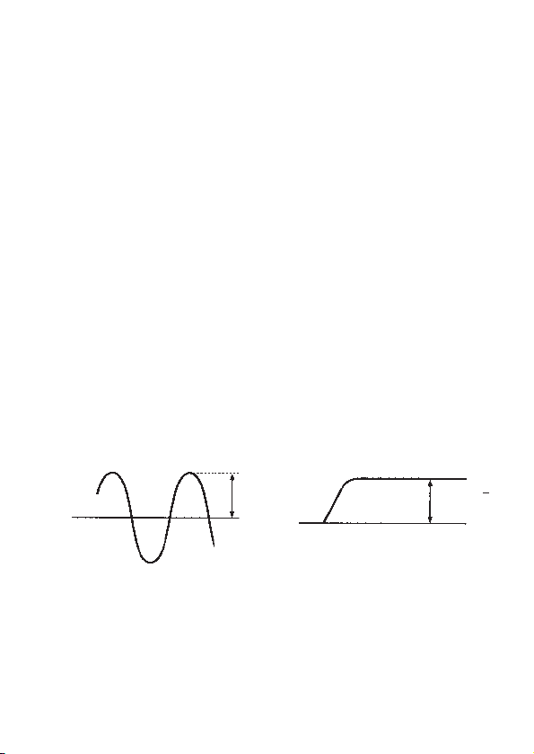
6−1−2 PeakCurrentMeasurement
①Set the function selector switch to the "〜400A" or "〜2000A" position.
②Press the mode switch to select the peak mode. "PEAK" will be
shown on the display.
③Press the trigger to open the transformer jaws and clamp them onto
the conductor under test. Then, press the reset switch.
④The display shows the current's crest value divided by the square
root of two. Therefore, when the current is sinusoidal, the reading
equals RMS value.
⑤To reset the display, press the reset switch.
(Note: When this is done, the reading goes off for about one second.)
⑥After the measurement is over, press the mode switch to return to
the normal mode.
NOTE
●In the peak measurement mode, the data hold feature is disabled.
●When a measured value is 9 counts or less, it is corrected to 0
(MODEL2002R).
Vp
INPUTCurrent
Vp/
2
PeakHold
Page 15

―38―
6−2 VoltageMeasurement
WARNING
●Do not make measurement on a circuit above 750V AC or 1000V
DC. This may cause shock hazard or damage to the instrument or
equipment under test.
●Do not make measurement with the battery compartment cover
removed.
6−2−1 DCVoltageMeasurement
①Set the function selector switch to the " V" position.
②Slide the terminal cover to the left. Plug the red test lead into the V/Ω
terminal and the black test lead into the COM terminal.
③Connect the other end of the test leads to the circuit under test.
Take the reading on the display. When the red lead is the negative
potential, the "ー" sign is shown on the display.
6−2−2 ACVoltageMeasurement
①Set the function selector switch to the "〜V" position.
②Slide the terminal cover to the left. Plug the red test lead into the V/Ω
terminal and the black test lead into the COM terminal.
③Connect the other end of the test leads to the circuit under test. Take
the reading on the display.
NOTE
● For high sensitivity, there are parts which do not indicate "0".
Blacktestlead
Redtestlead
Page 16

―39―
6−3 ResistanceMeasurement
WARNING
●Before attempting to make measurement, make sure that the
circuit under test is not live. The instrument is protected against a
voltage up to 600V.
●Do not make measurement with the battery compartment cover
removed.
6−3−1 ResistanceMeasurement(NormalMode)
①Set the function selector switch to the "Ω/" position.
②Slide the terminal cover to the left. Plug the red test lead into the V/Ω
terminal and the black test lead into the COM terminal.
③Short the tip of the test leads and check whether the display reads "0".
④Connect the tip of the test leads to the circuit under test. Take the
reading on the display.
NOTE
● When shorting the tip of the test leads, the display may read a very
small resistance instead of "0." This is the resistance of the test
leads, not a fault.
● If one of the test leads is open, the display reads "OL".
Black
testlead
Redtestlead
Page 17

―40―
6−3−2 ContinuityCheck
①Set the function selector switch to the "Ω/ " position.
②Slide the terminal cover to the left. Plug the red test lead into the V/Ω
terminal and the black test lead into the COM terminal.
③Press the mode switch to set the instrument to the continuity check
mode. The measuring range is fixed to 400Ω and the " " symbol
is shown on the display.
④Short the tip of the test leads and make sure that the display reads
"0" and the buzzer beeps.
⑤Connect the tip of the test leads to the circuit under test. The
display reads the resistance and the buzzer beeps when the
reading is not more than about 50Ω.
NOTE
● When shorting the tip of the test leads, the display may read a very
small resistance instead of "0". This is the resistance of the test
leads, not a fault.
● If one of the test leads is open, the display reads "OL".
Page 18

―41―
7−1 DataHold
This is a function used to freeze the measured value on the
display.
①Press the data hold switch. The reading becomes frozen and the
"H" symbol is shown on the display, indicating the instrument in the
data hold mode.
②To exit the data hold mode, press the data hold switch again to
release it.
NOTE
● When the function selector switch is turned while the instrument is
in the data hold mode, the data hold function remains activated.
To make measurement in this case, release the data hold switch
by pressing it and exit the data hold mode.
● The data hold function is disabled in the peak measurement mode
on the AC current range.
● When the sleep function is activated, the data hold mode turns to
the normal mode.
7−2 SleepFunction
This is a function to prevent the instrument from being left powered
on in order to conserve battery life.
①The instrument automatically enters the sleep (powered-down)
mode about 10 minutes after the last switch operation.
②To exit the sleep mode, press the data hold, reset or mode switch
or turn the function selector switch back to "OFF", then to any other
position.
[How to Exit the Sleep Mode ]
①Turn the function selector switch from "OFF" to another position with
the data hold switch pressed. Then, "P.OFF" is shown on the
display. This disables the sleep function and enables continuous
use of the instrument.
7.NotesonFunctions
Page 19

―42―
②To enable the sleep function, turn the function selector switch back
to "OFF", then to any other position.
NOTE
● The instrument consumes small amount of current in the sleep
mode. When the instrument is not in use, make sure to set the
function selector switch to "OFF".
7−3 RecorderOutput
Only on the "〜400A" or "〜2000A" range, DC voltage proportional
to the input current is output from the OUTPUT terminal.
①Set the function selector switch to the "〜400A" or "〜2000A"
position.
②Slide the terminal cover to the right and insert the recorder output
plug into the OUTPUT terminal for connection with a recorder or
other recording device.
NOTE
● Output voltage is 1mV/A on the "〜400A" range and 0.1mV/A on
the "〜2000A" range. Set an appropriate input sensitivity on the
recorder.
● The peak hold function does not apply to the recorder output even
if the instrument is in the peak hold mode.
● For long term measurement, disable the sleep function. (See
section 7-2 for sleep function.)
Page 20

―43―
[Howtoattachapairofleadstotherecorderoutputplug]
Attach one end of the leads to the recorder output plug observing
correct polarity, then connect the other end to the recorder.
DANGER
Never apply voltage to the output terminal.
7−4 ModeSwitchingFunction
On a AC current ("〜400A" or "〜2000A") or the resistance(Ω/)
range, press the mode switch to cycle through the measurement
modes. The instrument is initially set to the normal mode and can be
switched to the peak or continuity check mode by means of the mode
switch. (See section 6-1-2 for peak current measurement and section
6-3-2 for continuity check.)
Normal
Peak
Peakcurrentvalueisdisplayed.
(Responsetime:10ms)
"PEAK"isshownonthedisplay.
Pressthemodeswitch
Normal
ContinuityCheck
Thebuzzerbeepsiftheresistance
isnotmorethanabout50Ω.
Thebuzzersymbol isshown on
thedisplay.
≪ACCurrentRange(400Aor2000A)≫
≪ResistanceRange≫
Pressthemodeswitch
Pressthemodeswitch
Pressthemodeswitch
Page 21

―44―
WARNING
●To avoid electric shock hazard, make sure to set the function selector
switch to "OFF" and remove the test leads from the instrument before
trying to replace batteries.
CAUTION
●Do not mix new and old batteries.
●Make sure to install batteries in correct polarity as indicated in the
battery compartment.
NOTE
● If the instrument is powered on, but the display blanks or "BATT" is
shown on the display, replace the batteries.
①Set the function selector switch to the "OFF" position.
②Unscrew and remove the battery compartment cover on the bottom
of the instrument.
③Replace the batteries observing correct polarity. Use two new R6P
batteries.
④Replace and screw the battery compartment cover.
8.BatteryReplacement
Screw
Battery
Battery
compartment
cover
Page 22

―45―
9.OptionalAccessories
● Multi-Tran MODEL 8008 extends the capability of MODEL 2002PA
or MODEL 2002R, allowing measurement up to 3000A or on a
large bus-bar or conductor.
①Set the function selector switch to "〜400A".
②As shown in the figure below, clamp MODEL 2002PA or MODEL
2002R onto the pickup coil of MODEL 8008.
③Clamp MODEL 8008 onto the bus-bar or conductor under test.
④Take the reading on MODEL 2002PA or MODEL 2002R and
multiply it by 10.
MAX
150㎜
MAX
100㎜
Page 23

―46―
MEMO
Page 24

―47―
MEMO
Page 25

―48―
MEMO
Page 26

―49―
MEMO
Page 27

DISTRIBUTOR
92―1579A
03―08
Kyoritsu reserves the rights to change specifications or
designs described in this manual without notice and without
obligations.
 Loading...