

Page 1
INSTRUCTION MANUAL
VOLTAGE TESTER
KEW 1700 / 1710
KYORITSU ELECTRICAL
INSTRUMENTS WORKS, LTD
R
1. Features
●Designed to meet international safety standards.
IEC61243-3 / IEC61010-1
Measurement Category (CAT.) IV 600V
●Self-Diagnostic test
●AC and DC voltage test up to 690V with LEDs
and LCD ( only KEW1710 ).
●Polarity indication
●Single-pole phase test
●Phase rotation test
●Continuity test
●Auto-power ON / OFF
●Pen light for illuminating measurement points
●Two way clip for adjustable spacing of probes
●Selectable probe Tips 1.6/4mm
●Probe cover protects user and Tips
●IP65 (IEC60529)
●Compact design (Light weight and portable)
2. Safety Warnings
This instrument has been designed, manufactured
and tested according to IEC 61010/61243: Safety
requirements for Electronic Measuring apparatus,
and is supplied having passed rigorous quality
procedures.
This instruction manual contains warnings and
safety rules which have to be observed by the
user to ensure safe operation of the instrument
and to maintain it in safe condition. Therefore,
read through these operating instructions before using the instrument.
WARNING is reserved for conditions and ac-
tions that are likely to cause serious or fatal injury.
CAUTION is reserved for conditions and ac-
tions that can cause injury or instrument damage.
It is essential that the above instructions are
adhered to. Failure to follow the above
instructions may cause injury, instrument
damage and/or damage to equipment under test.
Symbols used on the instrument
User must refer to the explanations in
Instrument with double or reinforced
Insulated personnel body protective
CAT.IV The source of the low-voltage
CE Comply with EMC and Low Voltage
.
the instruction manual.
insulation, Class II insulation
equipment up to 690V.
installation:
Eg. Electricity meters and primary
overcurrent protection devices.
Estimated transient overvoltage 8kV.
Directive
WARNING
●Never make measurement on a circuit in
which the electrical potential exceeds 690V.
●Do not attempt to make measurement in the
presence of flammable gasses, as the use
of the instrument may cause sparking,
which could lead to an explosion.
●Never attempt to use the instrument if it’s
surface or your hands are wet.
(Do not use in rainfall.)
●Keep your hands and fingers behind the
barriers during measurements.
●Never unlock and open the Battery case
during measurements.
●Verify proper operation on a known source
before use or taking action as a result of the
indication after use.
●Never attempt to make any measurement if
any abnormal conditions, such as a broken
case or exposed metal parts are present on
the Instrument or test probes.
●Do not make any modification to the
instrument.
●Extreme caution when Live circuit LED
flashes or lights on.
●Correct indication of LEDs is only guaran
teed within a temperature range of -10°C up
to
55°C (<85% RH).
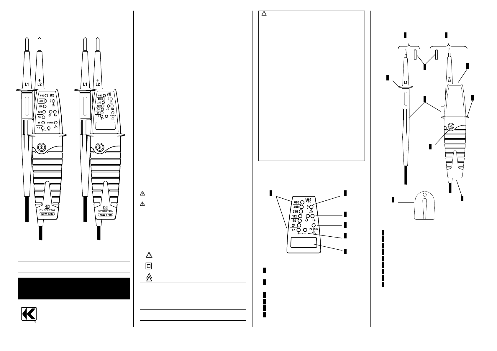
3. Instrument layout
1 2
1 12/24/50/120/230/400/690V LEDs
for voltage indication
2 Live circuit LED for Single-pole phase and
Double-pole test
3 L/R LEDs for phase rotation test
4 Power LED
5 Polarity indication LEDs for voltage
6 LCD (only KEW1710 )
3
4
5
6
1 L1 probe -
2 L2 probe + (Instrument probe)
3 4mm tips
4 Barrier
5 Pen light
6 Pen light switch
7 Battery case
8 Probe clip (two way)
9 Probe protection cover
1 2
3
4
8
6
9
5
4
7
Page 2
4. Preparation for measurement
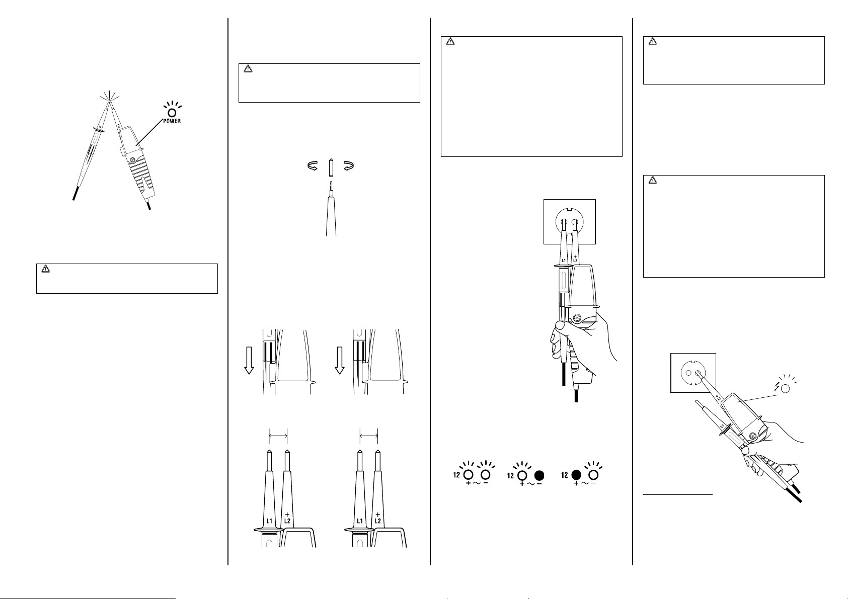
4.1 Auto-power-on / Self-diagnostic test
●Auto-power-on
►Short-circuiting the probes as follows powers
on the instrument automatically and goes into
a Self-diagnostic test.
Instrument may power on;
* when replacing Tips, or
* due to the influence of static charge.
●Self-diagnostic test
WARNING
Do not use the instrument when abnormality
is found at Self-diagnostic test.
►Battery voltage is normal when Power LED is
lighting up.
When the battery voltage is below 2.4±0.1V,
Power LED flashes or goes off.
Replace batteries according to Clause 7.
►LEDs other than the Power LED should be
flashing and buzzer should sound continuously.
●Auto-power off
►Instrument is automatically powered off after
15 sec when nothing is contacted with the
probes. (Power LED goes off.)
Auto-power off may not operate;
* when replacing Tips, or
* when a significant electric magnetic field exists
in the vicinity.
4.2 Trouble-shooting
If the following problems occur, unlock the
Battery Case according to clause 7 in this manual,
and then lock it again 5 seconds later.
Then perform the self- diagnostic test (clause 4.1).
* Self- diagnostic test cannot be performed
before/after use of the instrument.
* Auto-power off doesn’t operate.
5. Handy construction
Diameter of Tip and pitch between Tips are
changeable by user.
WARNING
Remove the probes from the measurement
point when replacing Tips or changing
pitches.
5.1 Tip Replacement
►Following shows how to install 4mm Tips on
L1 probe – and L2 probe +.
►Firmly tighten up the 4mm Tips.
unscrew
Tighten
5.2 Pitch between two probes
►Pitch between 2 Tips can be 16.7mm or 19.0mm
when rotating L1 probe – by 180 degrees and
sliding in the hooks on L2 probe +.
19mm16.7mm
6. Measurement
WARNING
●Carefully check Clause 2 as well.
●Self-diagnostic test should be done prior to
measurements and confirm LED and
Buzzer works properly.
●Verify proper operation on a known source
before and after use.
●Keep your hand and fingers behind the
barriers on the probes during
measurements.
●Due to the high internal resistance (approx.
300kΩ), the capacitive and inductive
voltages may be indicated.
6.1 Voltage test (Double-pole test)
►Connect both probes to the object under test.
►The voltage is indicated
by LEDs and LCD (only
KEW1710).
Buzzer sounds when a
threshold voltage of 50V
LED is exceeded.
Live circuit LED lights up :
> 0.3V AC
> 7V DC
►Voltage polarity is indicated in following
manner.
AC +DC -DC
NOTE
●This instrument can make measurements
between L-PE without tripping RCDs.
●When the L2 probe + is the positive (negative)
potential, the Polarity indication LED indicates
“+DC” (“-DC”).
●L/R LED may light up.
6.2 Double-pole test without batteries
WARNING
Verification of live-circuit shouldn’t be
dependent on Double-pole test without
batteries only, but also on the test WITH
BATTERIES. (See Clause 6.1).
Only Live circuit LED flashes when Double-pole
test is carried out without batteries.
LED flashes: AC/DCV > approx. 40V
Flashing Duty: < 3s (40…100V)
< 0.3s (100…690V)
6.3 Single-pole phase test
WARNING
●Carefully handle L1 probe – when it is not
in use.
●Function of this test may not be fully
achieved if the insulation condition of user
or of the equipment under test isn’t
enough.
Verification of live-circuit shouldn’t be
dependent on this Single-pole phase test
only, but also on the Double-pole test.
(See Clause 6.1.)
►Grasp the instrument firmly and connect the L2
probe + to the object under test.
►Live circuit LED lights up and buzzer sounds
when a voltage of approx. 100V AC or more
exists in the object under test. (Pol≥100VAC)
Grasp Firmly!!!
Page 3

6.4 Phase rotation test
L LED and R LED for Phase rotation test may
operate on various wiring systems, but effective
testing result can be obtained only on Three-phase
4-wire system.
►Grasp the instrument firmly and connect both
probes to the object under test.
►Phase-to-phase voltage is indicated by each
Voltage LED.
►R LED lights up for Right rotary field.
L3
L2
N
L1
PE
Grasp Firmly!!!
►L LED lights up for Left rotary field.
L3
N
L2
PE
L1
Grasp Firmly!!!
The principle of measurement
The instrument detects the phase rising order
regarding the user as EARTH.
NOTE
Function of this test may not be fully achieved if
the insulation condition of user or of the equipment
under test is not enough.
6.5 Continuity test
WARNING
Make sure the object under test isn’t live.
Instrument operates as follows when measuring
Continuity.
►All LEDs other than Power LED should be
flashing, and buzzer should sound continuously.
NOTE
In continuity mode the instrument works in the
same way as the self-diagnostic test.
6.6 Pen light function
(Illuminating the Measurement Point)
Equipped Pen light illuminates the measurement
point in dimly lit area.
►Pressing the Pen light switch turns on the light.
NOTE
●The light is available while the instrument is
powered off.
●Using the Pen light shortens the battery life.
7. Battery Replacement
WARNING
Remove the probes from any testing point,
when opening the Battery case.
Batteries are dead when Power LED flashes or
goes off at Self-diagnostic test defined in point
4.1. Follow the procedure below and replace
batteries with new ones(type IEC LR03 1.5V).
►Unlock the Battery case with a coin-shaped
object.
Lock Unlock
►Pull out the Battery case and replace the
batteries. Insert new batteries according to the
engraving on the Battery case.
►Insert the Battery case into the instrument and
firmly lock the case again.
WARNING
Confirm that the Battery case is propely
locked prior to measurements.
8. Specification
Voltage test
Voltage range 12…690V AC/DC
LED (KEW1700 / 1710)
Nominal voltage 12/24/50/120/230/400/690V
Tolerance
(Threshold voltage)
Response time
LCD (only KEW1710 )
Range / Resolution
(Auto-range)
Accuracy (23±5°C) ±1.5V (7…100V)
Overrange indication “OL”
Response time < 2s at 90% of each voltage
Peak current Is<3.5mA (at 690V)
Measurement Duty 30s ON (operation time)
Internal battery
consumption
Battery life Approx. 2500 operations
AC(45…400Hz), DC(±)
Light on at more than
: 7±3V (12V LED)
: 18±3V (24V LED)
: 37.5±4V (50V LED)
: 75%±5% of nominal voltage
(120/230/400/690V LED)
< 0.5s at 100% of each
nominal voltage
300V (7.0…299.9) / 0.1V
690V (270…759) / 1V
±1%±5dgt (100…690V)
AC(45…400Hz), DC(±)
240s OFF (recovery time)
Approx. 33mA (battery 3V,
measuring 690V AC)
(30s ON / 240s OFF duty)
Single-pole phase test
Voltage range
100…690V AC (45…100Hz)
180…690V AC (100…400Hz)
Phase rotation test
System
Phase range 120±5 degree
Three-phase 4-wire system
200…690V phase-to-phase
(100…400V earth-to-phase)
AC 50/60Hz
Continuity test
Detection range 0…400kΩ + 50%
Test current Approx. 1.5μA (battery 3V, 0Ω)
Internal battery
consumption
Approx. 30mA
(battery 3V, 0Ω)
Reference condition
Battery 3V (IEC LR03 1.5V x 2)
Temperature
Humidity Max 85% RH
Used location Altitude up to 2000m
-10…55°C operation
-20…60°C storage
No condensation
Safety
Standard
Category
Pollution degree 2
IP code IP65 (IEC60529)
IEC61010-1, CAT.III /IV 600V
IEC61243-3, CAT.II 690V
Size
Dimensions
Weight 230g (including batteries)
241.5 x 68.5 x 28.5mm
9. Cleaning and storage
CAUTION
●Use a lightly damp cloth with neutral detergent
for cleaning the instrument. Do not use
abrasives or solvents.
●Do not expose the instrument to the direct sun,
high temperature and humidity or dewfall.
●Put the Probe protection cover on the Tips
while not in use. Otherwise it may cause an
injury.
●Remove batteries when the instrument will not
be in use for a long period.
●Do not install the Battery Case without
batteries.
10. For Environment
This instrument is subject to WEEE
Directive (2002/96/EC). Please
contact your dealer near you at
disposal.
DISTRIBUTOR
Kyoritsu reserves the rights to change
specifications or designs described in this
manual without notice and without
obligations.
06/2006 92-1873
 Loading...