

Page 1
Troll Systems Corporation
Ground-Based Products
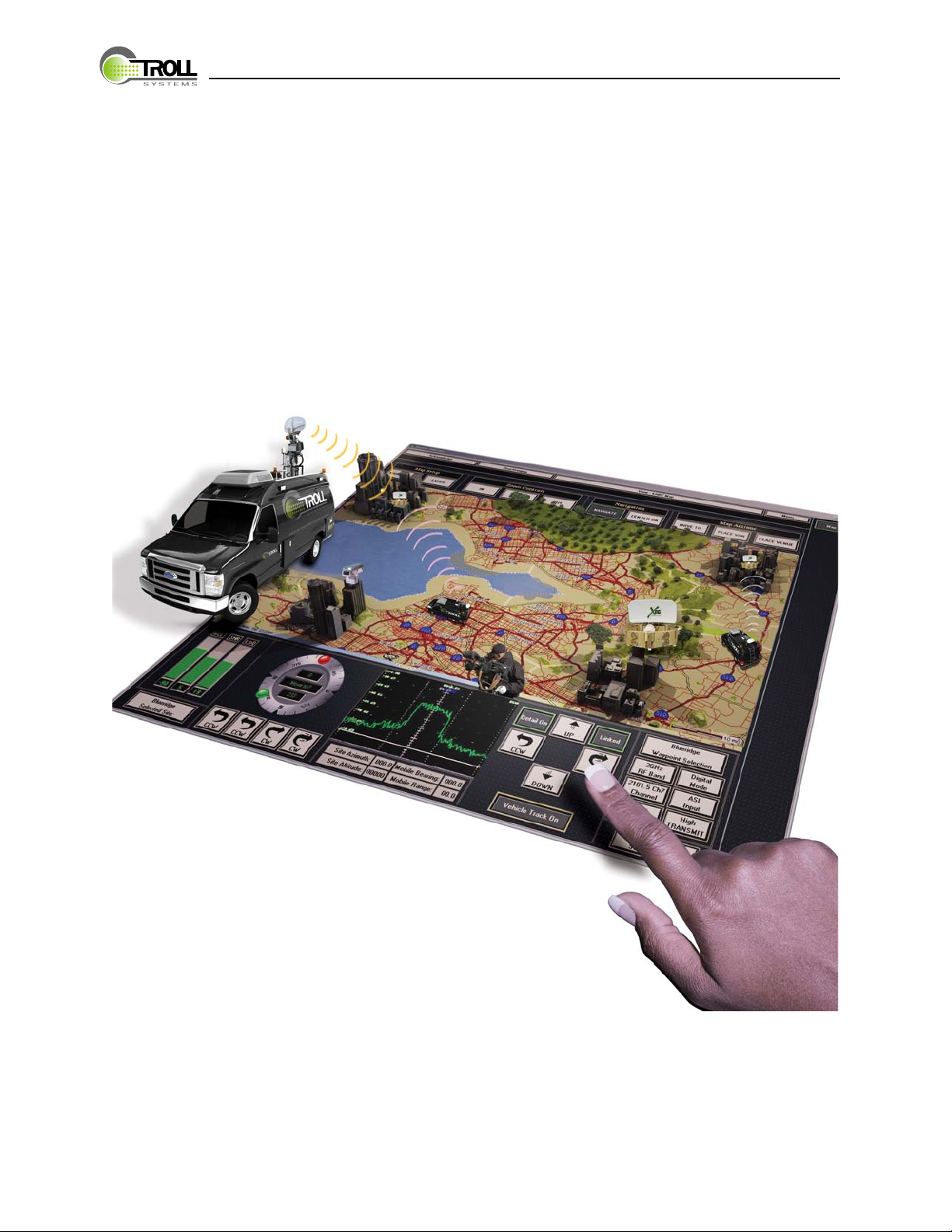
VanLink System
Installation Guide
Troll Systems Corporation Technical Publications
Document VLSG-01 Revision – 0
10/17/2008
www.trollsystems.com
Page 2

NOTICE
The information in this document incorporates proprietary rights of
Troll Systems Corporation
24950 Anza Avenue
Valencia, CA 91355, U.S.A.
Any party accepting this document acknowledges that it contains
proprietary confidential information and agrees that it shall not be
duplicated in whole or in part, nor disclosed to others without the
written consent of Troll Systems Corporation.
© 2008 Troll Systems Corporation
Page 3

VANLINK SYSTEM GUIDE
Table of Contents
Summary ...................................................................................................................................1
VanLink Equipment Components .............................................................................................1
Required Hardware ............................................................................................................... P-1
Software Requirements ......................................................................................................... P-1
Abbreviations, Acronyms, Terms ......................................................................................... P-2
Packaging .............................................................................................................................. P-4
Warranty ............................................................................................................................... P-4
Conventions Used in this Document ..................................................................................... P-5
VanLink Component Set-up and Operation ......................................................................... P-5
Warnings, Cautions, Notes, and Hints .................................................................................. P-5
Warnings ............................................................................................................................... P-5
Cautions ............................................................................................................................... P-6
Notes ..................................................................................................................................... P-6
Hints ..................................................................................................................................... P-6
Contact Information ............................................................................................................P-7
Hazard Advisory Placards/Signs ........................................................................................... S-1
Know and Comply with Local, State, and Federal Safety Requirements ............................. S-1
Do Not Service or Adjust Alone ...........................................................................................S-1
Electrical Power/Shock Hazards ...........................................................................................S-2
Be Familiar With Resuscitation Techniques ......................................................................... S-3
Coincidental Damage to Equipment in Cabinets .................................................................. S-3
Lifting/Handling Hazards ..................................................................................................... S-3
Electrostatic Discharge Sensitive (ESDS) Components ....................................................... S-4
System Overview .................................................................................................................. 1-1
VanLink System Features ............................................................................................... 1-2
Remote Control from the Studio or Control Center ....................................................... 1-3
SPECIFICATIONS ......................................................................................................... 1-4
Required System Components ........................................................................................ 1-4
Hardware Requirements ................................................................................................. 1-4
VanLink System featuring TouchStar™ Technology - Troll Systems Corporation
Document VLSG-01 - 10/21/08 -1
Page 4

Master Controller Software Requirements ..................................................................... 1-4
Introduction ..................................................................................................................... 2-1
Safety Recommendations ............................................................................................... 2-1
Installation Requirements ............................................................................................... 2-2
Power Requirements ....................................................................................................... 2-2
Rack Installation ............................................................................................................. 2-2
Rack Space Requirements .............................................................................................. 2-2
Cable Requirements........................................................................................................ 2-2
Running Cables .............................................................................................................. 2-3
V750 Cable and Connector Requirements ...................................................................... 2-3
Pan and Tilt Cabling and Connector Requirements ........................................................ 2-4
GPS/IMU Connectivity ................................................................................................... 2-5
EVDO/3G Router Connectivity ...................................................................................... 2-5
IP Connectivity ............................................................................................................... 2-5
Master Controller(s) and TNS Accessibility .................................................................. 2-5
Typical Network Configuration for VanLink ................................................................. 2-7
GPS/IMU Mounting Considerations .............................................................................. 2-7
GPS/IMU Assembly ....................................................................................................... 2-7
GPS/IMU Mounting Considerations .............................................................................. 2-7
VanLink GPS .................................................................................................................. 2-8
Calibration ...................................................................................................................... 2-9
Magnetometer Calibration .............................................................................................. 2-9
Antenna Calibration ........................................................................................................ 2-9
Remote and Local Control .............................................................................................. 2-9
Operating Requirements ............................................................................................... 2-10
Transmitter Control / Available Options ...................................................................... 2-10
Introduction ..................................................................................................................... 3-1
C100 User Interface VanLink System featuring TouchStar™ Technology - Troll Systems Corporation
-2 Document VLSG-01 - 1/11/2007
Page 5

VANLINK SYSTEM GUIDE
INTRODUCTION
This Installation Guide is intended for use with the VanLink System featuring
TouchStar™ Technology designed and fabricated by Troll Systems Corporation. The
sections and appendices that make up this manual are as follows:
Safety Considerations
Section 1 - Vanlink System Overview
Section 2 - VanLink System Requirements
Section 3 - Engineering Drawings
This guide or manual is based on the latest information available at the time of
publication.
SUMMARY
VanLink is a system composed of several Troll Systems components that are
coordinated work in a synchronous manner using proprietary software. This complex
and innovative system configuration enables complete studio control of a broadcast
news van while it is in the field.
VANLINK EQUIPMENT COMPONENTS
Required Hardware
The VanLink system is comprised of the following hardware components:
• V750 - Troll Systems Remote VanLink controller
• GPS/IMU – Troll Systems GPS & Magnetometer assembly
• Quickset Pan/Tilt – Pan/Tilt pedestal w/ Azimuth and Elevation feedback
• Pan/Tilt controller – Pan/tilt controller with remote interface capability
• EVDO or 3G Router
Software Requirements
• TouchStar 2008 – Windows application providing the control interface for VanLink.
• TouchStar 02 Mapping Software – Displays and provides control for all receive sites
including each vehicle equipped with VanLink.
VanLink System featuring TouchStar™ Technology - Troll Systems Corporation Introduction
Document VLSG-01 - 10/21/08 P-1
Page 6

INTRODUCTION
ABBREVIATIONS, ACRONYMS, TERMS
Listing of general abbreviations, acronyms, and terms that may be used throughout this
document are defined in the following list.
Term Definition
AC Alternating Current
ALT Altitude
ANT Antenna
AUX Auxiliary
Az Azimuth
BAS Broadcast Auxiliary Service
CAL Calibrate
CAM Camera
Ch Channel
COMM Communication
COTS Commercial-Off-The-Shelf
CPU Central Processing Unit
dB Decibel
DC Direct Current
DMM Digital Multimeter
e.g. Latin: exempli gratia, meaning “for example”
EMI Electro-Magnetic Interference
ENG Electronic News Gathering
ESD Electro-Static Discharge
et al Latin: et alia, meaning “and others”
FM Frequency Modulation
GPS Global Positioning System
GUI Graphic User Interface
HD High Definition
Hz Hertz
H/W Hardware
I/O Input/Output
i.e. Latin: id est, meaning “that is”
User Manual VanLink System featuring TouchStar™ Technology - Troll Systems Corporation
P-2 Document VLSG-01 - 10/17/2008
Page 7

ABBREVIATIONS, ACRONYMS, TERMS
Term Definition
LAT Latitude
LCD Liquid Crystal Display
LED Light Emitting Diode
LNA Low-Noise Amplifier
LNG Longitude
MICOWV Microwave
NEMA National Electrical Manufacturing Association
NIC Network Interface Card
nm (NM) Nautical Mile (note: 1 nautical mile equals 1.150782 miles)
NTSC National Television System Committee
NAV NavTrack
NV Non-Volatile
PC Personal Computer
PED Pedestal
POL Polarization
PRSETS Presets
RAM Random Access Memory
RF Radio Frequency
RFI Radio Frequency Interference
ROM Read Only Memory
RPC Remote Procedure Call
RX Receiver/Receive
S/W Software
SDI Serial Digital Interface
SV System Variable
TX Transmitter/Transmit
V Volt
VAC Volts Alternating Current
VDC Volts Direct Current
WWatt
VanLink System featuring TouchStar™ Technology - Troll Systems Corporation Introduction
Document VLSG-01 - 10/17/2008 P-3
Page 8

INTRODUCTION
PACKAGING
Use the original packaging material used for your TNS3000 network Server if available
and in good condition.
If you must return your product to Troll Systems Corporation for repair (and you no
longer have your original box and packing materials), Troll will send you a packing box
specifically designed to ship the product without damage.
WARRANTY
Troll warrants, to the original Customer only, that the product is free from defects in
material and workmanship and conforms to the specification, if any. If no specification
is listed, the items are warranted to conform to our currently published specification for
the product. The warranty period is for a period of one year from the date of shipment.
Troll will repair or replace (at its option) any such device which is returned to the Troll
factory office, with transportation charges prepaid and within the warranty period. The
liability of Troll shall be limited to the repair or replacement of the device and shall not
include installation, or any other charge or expense incurred. This warranty shall not
apply to any unit or part thereof which, in the opinion of Troll, has been installed or used
improperly; damaged by accident, corrosion, misused, or negligence; or altered or
repaired in such a manner as to impair performance. Troll must receive written notice of
the defect within the warranty period. Customer must pay packing, crating and
transportation costs to and from the factory. At the Customer’s request, Troll will make
reasonable efforts to provide warranty service at the Customer’s premises, provided that
Customer pays Troll’s then current rates for field service and the associated travel and
living expenses. If a fault has been caused by improper installation, maintenance or use,
or by abnormal conditions of operation, those repairs will be billed at normal rates. Troll
shall have the right of final determination as to the existence and cause of any such
defect.
User Manual VanLink System featuring TouchStar™ Technology - Troll Systems Corporation
P-4 Document VLSG-01 - 10/17/2008
Page 9

CONVENTIONS USED IN THIS DOCUMENT
CONVENTIONS USED IN THIS DOCUMENT
VanLink Component Set-up and Operation
The Troll Systems V750 Remote Site Controller and its innovative capabilities is the
heart of the VanLink system. For comprehensive information for this complex and
dynamic component, consult the Troll Systems manual for the S750 Remote Site
Controller manual which is identical to the V750 in almost all respects and functions.
Text appearing on the bottom line of the front panel display (just above the function
keys) of the V750 Remote site controller (i.e., commands associated with function keys
A, B, C, D, and E) appear in the font, Arial Rounded MT Bold
Text and terms that are emphasized to draw the reader’s attention (due to their
significance within the text) appear in italics. See the example below.
WARNINGS, CAUTIONS, NOTES, AND HINTS
Warnings
Warnings are included to alert the user that possible hazards are associated with the
processes/procedures described. These may cause death or injury in any form, if the
instructions in the operational or procedural task are not followed precisely. Warnings
describe the potential hazards and possible impact that could occur if the warnings are
not observed.
WARNING: This format is used for general warnings.
WARNING: This format is used for electrical warnings.
WARNING: This format is used for mechanical warnings.
VanLink System featuring TouchStar™ Technology - Troll Systems Corporation Introduction
Document VLSG-01 - 10/17/2008 P-5
Page 10
INTRODUCTION
WARNING: This format is used for warnings which include the risk
of fire.
Cautions
Cautions are included to alert the user that damage to the equipment is possible if the
instructions in the operational or procedural task are not followed precisely. Cautions
describe the hazards and possible impact that could occur if the cautions are not
observed.
CAUTION: This format is used for all cautions.
Notes
Notes are included to provide the user with supplemental information, which is helpful
but does not necessarily belong in the core text. Many operational and procedural tasks
are easier with the addition of notes.
NOTE: This format is used for all notes.
Hints
Hints are generally included to inform the user of special features and/or methods of
performing various tasks. These are usually unique features/methods that provide
streamlined use of the equipment and/or user interface.
Hint: This format is used for all hints.
User Manual VanLink System featuring TouchStar™ Technology - Troll Systems Corporation
P-6 Document VLSG-01 - 10/17/2008
Page 11

CONTACT INFORMATION
CONTACT INFORMATION
Troll Systems Corporation is committed to providing its customers with quick and
friendly service. If you have questions regarding your Troll product, or if you
experiencing a technical problem, please contact us at:
Troll Systems
24950 Anza Drive
Valencia, CA 91355
Phone: (661) 702-8900
Fax: (661) 702-8901
Alternatively, you can contact us via e-mail at:
Sales
sales@trollsystems.com
Service
service@trollsystems.com
Troll Systems Corporation is continually updating and enhancing its existing products
while also developing new products for the Electronic News Gathering (ENG) and
Airborne Law Enforcement (ALE) industries. Visit us on the world wide web at:
www.trollsystems.com
VanLink System featuring TouchStar™ Technology - Troll Systems Corporation Introduction
Document VLSG-01 - 10/17/2008 P-7
Page 12

INTRODUCTION
NOTES
User Manual VanLink System featuring TouchStar™ Technology - Troll Systems Corporation
P-8 Document VLSG-01 - 10/17/2008
Page 13

VANLINK SYSTEM GUIDE
SAFETY CONSIDERATIONS
GENERAL SAFETY PRECAUTIONS
The following general safety precautions are not related to any specific procedures and
therefore do not appear elsewhere in this publication. They are, however, precautions
that personnel need to understand and apply when operating or repairing equipment.
Installation, operation, and maintenance should be performed only by qualified
personnel.
Hazard Advisory Placards/Signs
Read and heed all hazard advisory placards or signs affixed to the equipment or
surrounding enclosures. They warn of potential hazards to personal safety and possible
damage to equipment if correct maintenance practices are not followed. Ignoring hazard
advisory placards (WARNINGS/CAUTIONS) places personnel at risk for serious injury or
death.
Know and Comply with Local, State, and Federal Safety Requirements
You should be familiar with all local, state, and federal safety requirements applicable to
the equipment, processes, and materials you use during maintenance. Before using any
substances or materials marked toxic or hazardous, always refer to the Material Safety
Data Sheets (MSDS) for that substance/material for any special protective equipment,
handling, and/or disposal requirements.
Do Not Service or Adjust Alone
Do not start a maintenance or adjustment procedure if that procedure requires more
than one technician to be safely performed. It is particularly important that such work
not be performed in a remote area, away from other qualified personnel who may be
needed to render assistance. When a maintenance task requires two or more personnel
to be safely accomplished, delay the task until qualified personnel are available to assist
you.
VanLink System featuring TouchStar™ Technology - Troll Systems Corporation Safety Considerations
Document VLSG-01 - 10/17/2008 S-1
Page 14

VanLink Safety Considerations
For safety reasons Troll Systems does not offer control of masts. There are, however,
methods for implementing safety measures to prevent any damage to the antenna or
surrounding equipment by monitoring the mast’s position and locking out control when
the mast is down. Due to the number of unique vehicle configurations and mast controls
available this shall be considered an option that will require additional preparation and
information from the customer/installer prior to implementation. Currently it is the
operator’s responsibility to ensure that the antenna is clear from any obstructions before
enabling remote control for the studio.
Electrical Power/Shock Hazards
WARNING: Potentially lethal voltage/current is present throughout
many electrical installations. Maintenance personnel
shall employ positive power lockout devices and post all
required warning tags/signs when applicable to ensure
that no unauthorized application of power can occur
during maintenance. Failure to heed this warning could
result in serious injury or death by electrocution.
Always verify that electrical power is disconnected and that applicable safety procedures
have been followed before doing maintenance on any electrical/electronic equipment.
High voltage electrical energy is stored in some electrical equipment (electrolytic
capacitors, UPS batteries, etc.) even after the source of primary external power has been
disconnected. Always remove external power, deactivate equipment, or discharge the
potential to ground (when applicable) before working on the equipment.
If a high-potential insulation test is required, follow the procedures and precautions
outlined in the appropriate National Electrical Manufacturing Association (NEMA)
standards. Check with the area supervisor if unfamiliar with these standards, specific
equipment, or procedures.
When electrical troubleshooting of a system must be accomplished with power applied,
first verify that all personnel in the hazard area are advised, that the equipment is
tagged, and/or that an assistant is posted at the point of power control.
User Manual VanLink System featuring TouchStar™ Technology - Troll Systems Corporation
S-2 Document VLSG-01 - 10/17/2008
Page 15

Be Familiar With Resuscitation Techniques
Personnel working with or near high voltages should be familiar with modern methods
of resuscitation. It is beneficial to ensure that personnel are capable of performing
Cardio-pulmonary resuscitation (CPR) should the need arise.
Coincidental Damage to Equipment in Cabinets
CAUTION: Pushing or forcing equipment into/out of equipment
cabinets and enclosures can easily damage surrounding
equipment, cables/wiring, or fiber optic cable installations.
Be alert to avoid coincidental damage to equipment when
accessing crowded installations. Coincidental damage is
often difficult to detect and even more difficult to
troubleshoot.
When removing equipment from cabinets/consoles, exercise care so that surrounding
wiring installations and equipment are not physically damaged in the process.
Disconnect and secure any surrounding wiring or hardware which could cause damage
to or be damaged by the equipment being removed.
When installing equipment into cabinets/consoles, exercise care to protect surrounding
wiring installations and equipment from being physically damaged in the process.
Neatly stow excess cable/wiring and replace all tie wraps, clamps, and other retaining
devices which were removed. Neat installations reduce the chances of coincidental
damage to adjacent equipment and promote more efficient air circulation and equipment
cooling.
Lifting/Handling Hazards
The removal and installation of large, heavy, or awkward component assemblies,
especially equipment attached to the external areas of the aircraft, will require a
minimum of two (2) personnel to safely handle. Alternatively, the use of appropriately
rated material handling equipment can be used when determined to be safe. Where
limited access prevents the use of material handling equipment, ensure that an adequate
number of personnel are present to safely handle the anticipated loads.
VanLink System featuring TouchStar™ Technology - Troll Systems Corporation Safety Considerations
Document VLSG-01 - 10/17/2008 S-3
Page 16

Electrostatic Discharge Sensitive (ESDS) Components
CAUTION: Beware of electrostatic buildup. Delicate solid-state
Integrated Circuits (ICs) can be damaged by improper
handling procedures. Use proper electrostatic safeguards
when installing/removing circuit cards and handling ESD
sensitive assemblies. As required, wear a grounded wrist
strap, use antistatic floor and table mats, and minimize the
handling of sensitive solid-state devices. Keep all ESD
sensitive components in their original containers until
ready for use. Always discharge personal static before
handling ESD sensitive components and do not slide solid
state devices over any surface. Handle plug-in card
assemblies only by their non-conductive edges.
Computers, microprocessors, and other solid state components (circuit cards,
I/O boards, etc.) which are not clearly marked with the ESDS symbol will be handled as
ESD sensitive components until determined otherwise. Retain protective ESDS packing
and shipping bags, containers, non-conductive foam pads, etc. (see Figure S–1) for use
in the return of repairable components.
User Manual VanLink System featuring TouchStar™ Technology - Troll Systems Corporation
S-4 Document VLSG-01 - 10/17/2008
Page 17

Minimize Handling. Keep parts in original containers
until ready for use.
Discharge personal static
before handling devices.
Handle devices by the body. Use anti-static containers for
handling and transport.
Avoid plastic, vinyl and
styrofoam in work area.
When removing plug-in
assemblies, handle only by
non-conductive edges and
never touch open edge
connector except at static-free
work station. Placing shorting
strips on edge connector
usually provides complete
protection to installed devices.
Do not slide devices over any
surface.
Handle devices only at a staticfree work station.
Only anti-static type solder
suckers should be used.
Only grounded tip soldering
irons should be used.
Figure S–1. Procedures for Handling Electrostatic Sensitive Components
VanLink System featuring TouchStar™ Technology - Troll Systems Corporation Safety Considerations
Document VLSG-01 - 10/17/2008 S-5
Page 18

NOTES
User Manual VanLink System featuring TouchStar™ Technology - Troll Systems Corporation
S-6 Document VLSG-01 - 10/17/2008
Page 19

SECTION 1
VANLINK SYSTEM OVERVIEW
1.1 SYSTEM OVERVIEW
The Troll Systems VanLink remote broadcast van control interface is a comprehensive
and dynamic system designed to be integrated into vehicles utilized in Electronic News
Gathering functions in the field. Refer to Figure 1–1 through Figure 1–3.
VANLINK SYSTEM GUIDE
Van External
Control Panel
with QPT set
to Remote
CONTROL
CONTROL
Van External
Control Panel
with QPT set
to Remote
Troll Systems V750
Remote Site Controller
Transmitter
to V750 serial input
Field Vehicle with Tx, GPS
and Magnetometer
controlled remotely by
studio operator
TOUCHSTAR
S750
COMM
COMM
FEEDBACK
Van Tx Antenna
with Pan and Tilt
Rooftop or Antenna
Mounted IMU
12 wire Nycoil
from V750 to
Tx Antenna
CONTROL
EVDO to V750 Ethernet
with Static IP or Dynamic DNS
QPT - 90/115 with
Local and Remote Controller
WAN
CONTROL
Figure 1–1. VanLink System ENG Vehicle Configuration
VanLink System featuring TouchStar™ Technology - Troll Systems Corporation VanLink System Overview
Document VLSG-01 - 10/21/08 1-1
Page 20

SYSTEM OVERVIEW
1.1.1 VanLink System Features
This system enables several operations of the ENG vehicle to be controlled remotely
from the broadcast studio including such key functions as:
• Remote tracking of vehicle heading and location including locations of all vehicles
that are mutually equipped with VanLink
• Troll MC17 Master Controller with Graphic User Interface featuring the control page
and GPS enabled screen MAP
• Transmitter antenna control including pan and tilt for azimuth and elevation feedback
• Optional roof mount or mast mount of the GPS/IMU to minimize EMI interference
• Automatic tracking of the HD signal with self-optimization of the vehicle transmitter
antenna in real time using the V750’s preprogrammed ability to analyze and
compensate for signal integrity in reference to the studio’s coordinates and the
vehicle’s GPS/IMU location feedback. (see Figure 1–2)
Troll Systems V750 Remote Site Controller
communicating with van IMU GPS and Magnetometer while
coordinating with preprogrammed site latitude and
longitudinal data for accurate signal tracking in real time
GPS
Magnetometer
TOUCHSTAR
S750
IMU
Figure 1–2. VanLink IMU Configuration
User Manual VanLink System featuring TouchStar™ Technology - Troll Systems Corporation
1-2 Document VLSG-01 - 10/21/08
Page 21

1.1.1.1 Remote Control from the Studio or Control Center
Comprehensive remote control of ancillary vehicle functions including pan and tilt,
vehicle tracking and signal optimization. (see
Troll Systems MC17
Master Controller
with GUI Page / Map
Figure 1–3).
PC
SYSTEM OVERVIEW
Switcher / Router
WAN
Figure 1–3. VanLink Remote Studio Configuration
VanLink System featuring TouchStar™ Technology - Troll Systems Corporation VanLink System Overview
Document VLSG-01 - 10/21/08 1-3
Page 22

SPECIFICATIONS
1.2 SPECIFICATIONS
1.2.1 Required System Components
1.2.1.1 Hardware Requirements
The VanLink system of comprised of the following hardware components:
• V750 - Troll Systems VanLink controller
• GPS/IMU – Troll Systems GPS & Magnetometer assembly
• Quickset Pan/Tilt – Pan/Tilt pedestal w/ Azimuth and Elevation feedback*
— 115VDC
• Pan/Tilt controller – Pan/tilt controller with remote interface capability
— C90VS-DC115A
• EVDO or 3G Router** – Cellular data service router which utilizes either a Static
public IP address or Dynamic DNS***
—Kyocera One
*Optional potentiometer kits are available for most units
**Requires additional EVDO/3G card with service activated
***May incur monthly charges for additional Dynamic DNS services
1.2.1.2 Master Controller Software Requirements
The VanLink system of comprised of the following software components at the Master
Controller:
• TouchStar 2008 – Windows application that provides control interface for VanLink
including any additional device control that has been implemented.
• TouchStar 02 Mapping Software – Displays and provides control for all receive sites
including each vehicle equipped with VanLink.
User Manual VanLink System featuring TouchStar™ Technology - Troll Systems Corporation
1-4 Document VLSG-01 - 10/21/08
Page 23

SECTION 2
VANLINK SYSTEM REQUIREMENTS
2.1 INTRODUCTION
This section provides information detailing the system requirements and theory of
operation of the Vanlink Control System. The following topics are discussed:
• Safety Recommendations
VANLINK SYSTEM GUIDE
• System Requirements
• Theory of operation and recommendations
2.2 SAFETY RECOMMENDATIONS
Equipment installation and operation should only be performed by qualified personnel
that are familiar with the type of equipment being installed.
The following guidelines will help ensure your safety and protect the equipment from
damage. However, these guidelines do not cover all potentially hazardous situations you
might encounter during system installation. Refer also to the Safety Considerations of
this guide for additional safety information.
• Always disconnect all power connections before installing or removing the Vanlink
System and its associated components (i.e. the V750 Master Controller).
• Keep the rack and/or installation area clear and free of dust during and after
installation.
• Keep tools and chassis components away from walk areas.
• Comply with all local safety laws and guidelines.
• Do not wear loose clothing, jewelry (including rings and chains), or other items that
could get caught in the equipment. Fasten or remove loose ties, scarves, sleeves,
and other items before you start installation procedures.
• Equipment grounding must meet local and national electrical codes.
VanLink System featuring TouchStar™ Technology - Troll Systems Corporation VanLink System Requirements
Document VLSG-01 - 10/21/08 2-1
Page 24

INSTALLATION REQUIREMENTS
2.3 INSTALLATION REQUIREMENTS
The Vanlink System components install easily in a standard 19-inch equipment rack.
Physical characteristics of the Vanlink System components are provided in the
applicable assembly drawings. Both standard and custom rack installations must meet
these dimensional requirements in order to properly accommodate the installation of
the controller.
2.3.1 Power Requirements
Power provided at the vehicle must meet either of the following requirements:
• 120VDC for the V750 Remote Site Controller
• 120VDC for the Router
• 120VDC for the V750 Pan and Tilt Controller
2.3.2 Rack Installation
Vanlink System components rack space requirements are as follows:
2.3.2.1 Rack Space Requirements
• V750 – Requires two rack spaces
• Pan/Tilt controller – Requires two rack spaces unless otherwise specified
• EVDO/3G Router – One rack space (not necessarily rack mounted)
2.3.3 Cable Requirements
All applicable cables may be able to be installed (with the ready connectors) after
installing the Vanlink System components into the equipment rack. Connectors and
cables may vary depending upon each customer’s installation requirements.
Cables may be fabricated in the factory. In some cases, customers may choose to
fabricate the cables themselves to custom lengths for the best possible configuration or
fit within their equipment rack. It is recommended to refer to the System Interconnect
Diagram that will accompany your system to determine the cable requirements for your
system.
User Manual VanLink System featuring TouchStar™ Technology - Troll Systems Corporation
2-2 Document VLSG-01 - 10/21/08
Page 25

2.3.3.1 Running Cables
Cables should only be installed by qualified personnel who are familiar with the electrical
requirements and safety precautions that are necessary to properly and safely install
(run) these items.
The cables should be inspected prior to installation. Connectors should be visually
inspected prior to connecting to their mating connector.
2.3.3.2 V750 Cable and Connector Requirements
The V750 cable and connector requirements are as follows:
• Cabling consisting of four (4) wires will be required between the V750 and the
pan/tilt for azimuth and elevation feedback.
— Some pan/tilts may already have the potentiometers installed in which case the
wires needed may already be terminated and run through the NYCOIL.
INSTALLATION REQUIREMENTS
• The harness for the GPS/IMU can be extended to reach the roof of the vehicle if
necessary.
Refer to Figure 2–1
p/n
TBD
Figure 2–1. Cable Connector/Adapters E-201-0101-01
VanLink System featuring TouchStar™ Technology - Troll Systems Corporation VanLink System Requirements
Document VLSG-01 - 10/21/08 2-3
Page 26

INSTALLATION REQUIREMENTS
2.3.3.3 Pan and Tilt Cabling and Connector Requirements
The pan and tilt cable and connector requirements are as follows (refer to Figure 2–2):
• The pan/tilt controller is connected directly to the QPT pedestal on the roof via a
terminal strip in the rear of the controller.
— An additional four (4) wires are required for azimuth/elevation feedback.
— The four (4) wires will connect to the V750 or to the pan/tilt controller depending
on whether or not the model has feedback capability.
— For installations using the C90VS-DC115A, the 4 wires will terminate at the 26p
circular connector on the rear of the V750.
Twelve (12)
Wire Nycoil
Figure 2–2. Typical Network Configuration
User Manual VanLink System featuring TouchStar™ Technology - Troll Systems Corporation
2-4 Document VLSG-01 - 10/21/08
Page 27

2.3.3.4 GPS/IMU Connectivity
• Cabling consisting of six (6) wires will need to run from the V750 to the GPS/IMU.
— It is possible to use existing wires to avoid running new wires by creating an
extension with a DB9 connector on each end of the wires. Otherwise the cable
from the GPS/IMU will be run from the roof down to the V750 where it will
connect to the harness.
• +12VDC power is provided by the V750
2.3.3.5 EVDO/3G Router Connectivity
• Requires EVDO/3G PCMIA Card with service activated (provided by customer on
their service plan).
• Requires 120VDC
• Requires one CAT5 cable
2.3.4 IP Connectivity
INSTALLATION REQUIREMENTS
In order for VanLink to work remotely from the studio, the MC-17s and TNS (if equipped
with Controll2_TNS1 software) must have access to the internet (WAN). Most studios
have a unique configuration as well as their own unique security measures and policies
which must be discussed and necessary preparations should be coordinated with their
own respective IT departments. The minimum open port requirements for the master
controller(s) running TouchStar to establish communications with the V750 inside the
vehicles running VanLink are as follows:
2.3.4.1 Master Controller(s) and TNS Accessibility
Master Controller(s) and TNS (if equipped with Controll2_TNS1 software) must have
access to the outside internet (see Figure 2–3).
• Open ports required are: 80, 2000, 2009, 2050, and 2099
— Port 80* (TCP/IP) is the HTTP port required for the MC-17 or TNS to resolve
Dynamic DNS IP addresses.
— Port 2000 (TCP/IP & UDP) is for terminal access (TELNET) for remote
configuration of the V750 primarily via the Forge application
— Port 2009 (UDP) is the port TouchStar uses to communicate with the program
running at the V750
— Port 2050 (TCP/IP) is the port used also used for terminal access for
applications other than Forge
— Port 2099 (TCP/IP & UDP) is another port being utilized by Forge for remote
configuration
VanLink System featuring TouchStar™ Technology - Troll Systems Corporation VanLink System Requirements
Document VLSG-01 - 10/21/08 2-5
Page 28

INSTALLATION REQUIREMENTS
NOTE: Port 80 is not required if the EVDO/3G router utilizes a static
IP address
Troll Systems
TNS3000 Network Server
Studio Network Router
Figure 2–3. Typical VanLink Network Configuration
User Manual VanLink System featuring TouchStar™ Technology - Troll Systems Corporation
2-6 Document VLSG-01 - 10/21/08
Page 29

2.3.5 Typical Network Configuration for VanLink
2.3.5.1 GPS/IMU Mounting Considerations
In order for the GPS/IMU to continually provide accurate heading information a few
considerations need to be made when mounting the assembly on the roof of the vehicle.
• The GPS/IMU assembly must be mounted as far away from any significant sources
of current such as flood lights or motors as possible because it is sensitive to EMI
generated by these types of devices.
• It’s recommended that it be installed at least 24” from the pan/tilt device so as not to
be affected by the EMI generated by the DC motors.
• The GPS/IMU can be mounted either on the mast using a bracket or on the roof of
the van in an area least likely to be affected by EMI.
— If it is mounted on the mast, six (6) additional wires will be needed to be run
through the NYCOIL.
GPS/IMU ASSEMBLY
2.4 GPS/IMU ASSEMBLY
2.4.1 GPS/IMU Mounting Considerations
If the GPS/IMU (see Figure 2–4) is to provide continuously accurate heading
information. a few mounting considerations need to be made when the assembly is to
be installed onto the roof of the vehicle.
• The GPS/IMU assembly must be mounted as far away from any significant sources
of electrical current as possible such as flood lights or motors because its sensitivity
to the EMI generated by these types of devices.
— It is recommended that the GPS/IMU be installed at least 24” from the pan/tilt
device so it will not to be affected by the EMI generated by the DC motors.
• The GPS/IMU can be mounted either on the mast using a bracket or on the roof of
the van in an area least likely to be affected by EMI.
• If it is mounted on the mast, six (6) additional wires will be needed to be run through
the NYCOIL
VanLink System featuring TouchStar™ Technology - Troll Systems Corporation VanLink System Requirements
Document VLSG-01 - 10/21/08 2-7
Page 30

GPS/IMU ASSEMBLY
Figure 2–4. GPS/IMU Assembly
2.4.2 VanLink GPS
One of the key functional features of VanLink is its ability to utilize the vehicles current
location (Latitude/Longitude), its orientation (Reference to magnetic North), and the
static coordinates of each receive site in order to point the dish to the appropriate
azimuth. For this feature to be operational, Troll Systems will require a list of each
receive site and its coordinates (preferably in DD:MM.MM – Degrees Minutes
Hundredths of a Minute) to be programmed into the V750 in advance of system field
operation.
Additional sites can be added at any time. The procedure will require an update to both
the V750 and TouchStar. Typically, the update to the V750 can be accomplished from the
studio provided that there are communications established between the vehicle and
TouchStar (hence all of the open ports required).
User Manual VanLink System featuring TouchStar™ Technology - Troll Systems Corporation
2-8 Document VLSG-01 - 10/21/08
Page 31

2.5 CALIBRATION
There are two components of VanLink requiring calibration that need to be performed
prior to successful operation of the VanLink operational system. The first component to
be calibrated is the magnetometer. The second component to be calibrated is the
antenna.
2.5.1 Magnetometer Calibration
After installation, the magnetometer (part of the GPS/IMU assembly) needs to be
calibrated. This procedure acquires a magnetic footprint created by any surrounding
magnetically impeding structures on/in the vehicle so, regardless of the it’s orientation
to magnetic north, the V750 can accurately pinpoint the current heading.
• In order to perform calibration on the IMU (magnetometer), the vehicle must be in a
location free of magnetic interference and as far away as possible from any nearby
structures which could potentially interfere with the magnetometer’s reference to
North.
CALIBRATION
• The vehicle must be capable of driving in a tight 360 degree circle with a laptop that
is connected to the GPS/IMU and running the calibration software.
2.5.2 Antenna Calibration
Typically calibrated to Magnetic North (to maintain compatibility with the Troll Systems
standard configuration NavTrack feature), the antenna’s orientation is calculated with an
offset to the magnetometer’s current heading. This is required to accurately orient the
dish to each respective receive site in reference to the vehicle’s GPS coordinates and
orientation to North.
2.6 REMOTE AND LOCAL CONTROL
Even without remote control, VanLink is a powerful tool. An operator can quickly press a
few buttons and have the antenna accurately align itself to the desired receive site with
very little training required. While the V750 is in LOCAL mode, only personnel in the
vehicle have control of the V750.
Full control of the antenna, including site selection as well as most control for any
additional devices, is available from the front panel. It is possible to remotely reset the
V750 to enable remote control; otherwise the personnel in the vehicle must enable
remote control from the front panel of the V750.
VanLink System featuring TouchStar™ Technology - Troll Systems Corporation VanLink System Requirements
Document VLSG-01 - 10/21/08 2-9
Page 32

OPERATING REQUIREMENTS
2.7 OPERATING REQUIREMENTS
In order for VanLink to be effective there has to be GPS coverage and a clear microwave
path for ENG operations from where the vehicle is located.
For remote control of VanLink, the vehicle will also need to be in an area that has the
coverage from the customer’s particular cellular service provider.
2.7.1 Transmitter Control / Available Options
There are Control-PACs already written for most transmitters in use for ENG. Most
commonly used are MRC’s Strata, PTX-Pro, and CR2 along with Nucomm’s Channel
Master and NewsCasters series. Besides transmitter control, there are an almost infinite
number of possibilities for remote control of other components using the V750. For
example, it would be relatively easy to remotely control the vehicle’s door locks or
additional devices mounted in the vehicle’s racks. Some devices may require drivers to
be written for control, while others may require only simple contact closures. Feel free
to contact a Troll Systems representative to learn more about the many possible
solutions that VanLink can improve the your ENG operations needs.
User Manual VanLink System featuring TouchStar™ Technology - Troll Systems Corporation
2-10 Document VLSG-01 - 10/21/08
Page 33

SECTION 3
ENGINEERING DRAWINGS
3.1 INTRODUCTION
This section contains top level engineering drawings, such as assembly drawings,
schematics, and interconnect diagrams that define the configuration of the equipment
used in a typical VanLink System
VANLINK SYSTEM GUIDE
Vanlink System featuring TouchStar™ Technology - Troll Systems Corporation Engineering Drawings
Document VLSG-01 - 10/21/08 3-1
Page 34

Page 35

Page 36

Page 37

Page 38

Page 39

Page 40

Page 41

 Loading...