

Kyocera SDS INSTALLATION
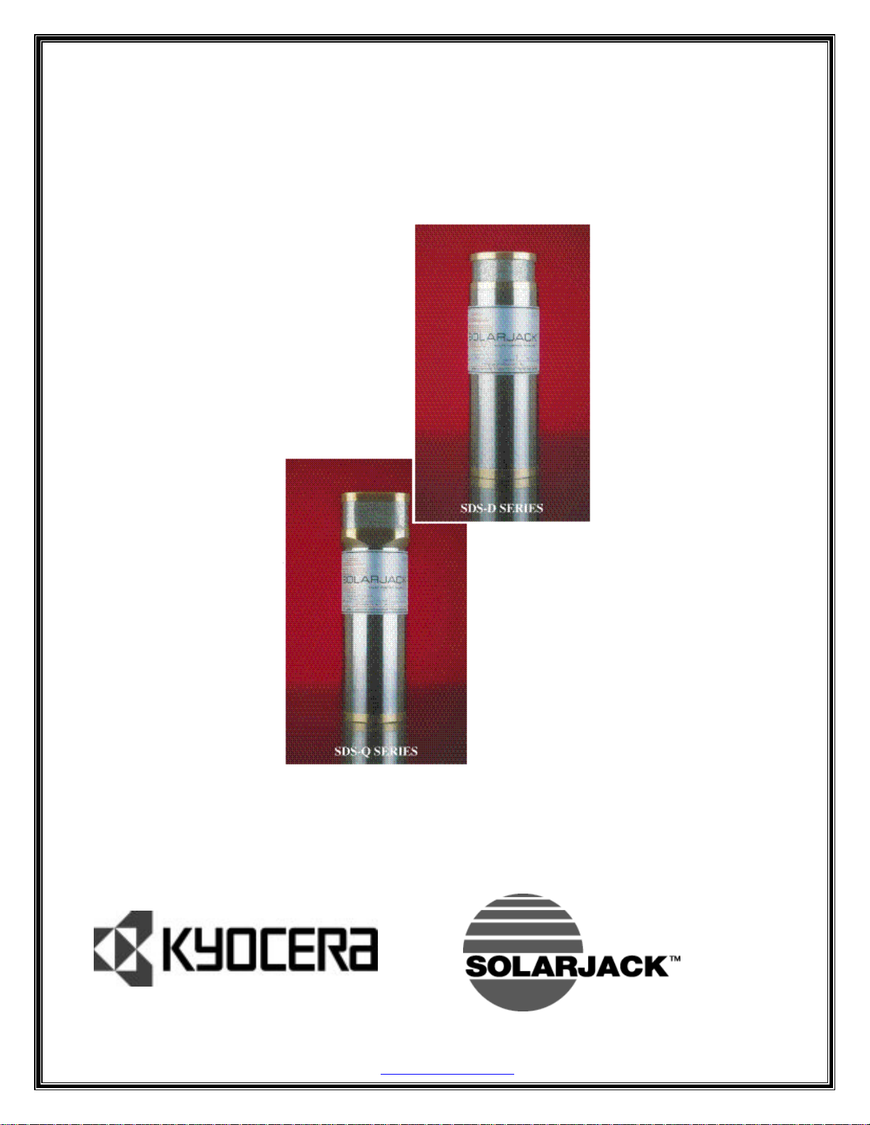
SDS SERIES
DC SUBMERISIBLE PUMPS
REBUILD MANUAL
Kyocera Solar, Inc. / SOLARJACK, 7812 E. Acoma Drive, Scottsdale, AZ 85260
Telephone (800) 223-9580 FAX (480) 483-6431
www.kyocerasolar.com
E-mail info@kyocerasolar.com

SDS PUMP REBUILD INSTRUCTIONS
Rev.4/92
1. Remove cable guard screws (Item 1).
2.
3. Remove the two socket head screws (Item 26) from end cap (Item 6) using
4. Clamp the pump in the puller and screw the proper threaded mandrel in
5. Pull the end cap out of the stainless housing. If the brass ends seem to
6. With the end cap removed from the housing, turn the pump around, screw
7. Remove the four socket head screws (Item 25) from the discharge head
8. Remove the bypass valves and springs (Items 19 & 20), suction 5creen
9. Remove the two motor adapter screws (Items 4) using a 5/32”, hex wrench.
10. Pull the motor adapter and cam assembly away from the motor, remove the
11. Discard the support collars (Item 14), O-ring6 (Items 9), diaphragm (Item
12. Clean and inspect all remaining parts and make sure that the electrical
Remove 1/8” pipe plug (Old Style) or 3/8” NC set screw (New Style)
(Item 5) using a 3/16" hex wrench.
HIGH PRESURE. USE EXTREME CAUTION IN REMOVING END CAP PLUGS AND END CAP
SCREWS.
a 5/32" hex wrench.
the end cap.
be stuck, warm the stainless housing slightly with a small propane
torch, being careful not to overheat and warp the housing. As the end
cap (Item 8) comes out, disconnect the two motor wires plugged into the
end cap.
the appropriate mandrel into the discharge head, and remove the pump
assembly from the stainless housing.
using a 5/32", hex wrench.
(Item 24), check valve assembly (Item 21), and gasket (Item 22) from the
discharge head.
blunt tool through the discharge opening.
Remove the set screw from the cam assembly (Item 13) using a long 1/8”,
hex wrench. This wrench must be inserted through the hole in the side of
the motor adapter (Item 16). Before inserting the wrench, visually align
the set screw with the hole by turning the motor adapter while holding
the motor.
two piston screws (Item 12), and then the cam assembly (Item 13).
17), check valve (Item 23), and gasket (Item 22).
studs protruding from the epoxy in the end cap are in good condition and
the epoxy is still hard.
Note
: Check valve removal may require a lite tap with a
WARNING: PUMP HOUSING MAY BE UNDER
12/06/99 2

SDS PUMP REBUILD INSTRUCTIONS
ASSEMBLY
1. Set the brass pistons (Items 18) flat side down on the pump assembly
plate, positioning the two holes over the locating studs.
2. Place the diaphragm (Item-17), with the offsets up, over the pistons
locating the piston shafts through the two holes.
3. On an SDS-D-128 use only the white santoprene diaphragm. 0n an SDS-D-228
use only the black EPDM diaphragm and install the Teflon wear washer
(Item 15) around the piston shaft.
GREASE ON EITHER DIAPHRAGM, IT MAY CALUSE DIAPHRAGM FAILURE
4. Slip the support collars (Item 14) over the shafts with the radius side
toward the diaphragm.
5. Set the motor adapter (Item i6) face down over the diaphragm assembly
allowing the piston to protrude through the two holes being careful not
to nick or cut the diaphragm.
6. Put the set screw into the cam and insert the cam assembly (Item 13) over
the piston shaft making sure the piston shafts fit into the cam plate
holes.
7. Insert the two piston screw (Item 12) through the cam assembly, and
tighten with a 5/32”, hex wrench to 60 inch lbs. of torque. (Be careful
not to allow the pistons to slip off the locating studs while tightening
the screws.) Each screw should be tightened a little at a time
alternating between each side. This will pull both pistons into alignment
before either piston clamps the diaphragm.
8. Place the motor on the assembly board with the shaft up. Turn the motor
shafts until the flat side faces you.
9. Coat the inside of the cam hole and the outside of the motor shaft with
silver anti-seize (NAPP. part no. 765-1674, is recommended).
10. Insert a long 1/8”, hex wrench through the hole in the motor adapter and
into the cam set screw.
11. Slip the cam assembly over the motor shaft aligning the set screw to the
center of the flat on the shaft. As the cam assembly is inserted over the
motor shaft tighten the set screw until it lightly touches the motor
shaft and then back it off 1/8 turn. Continue installing the cam assembly
until the motor adapter butts up to the motor. Then push on the pistons
until the cam assembly bottoms on the motor shaft. While holding the
piston down firmly, tighten the set screw.
CAUTION- NEVER USE ANY TYPE, OF
.
12/06/99 3
 Loading...