

Page 1
INSTALLATION MANUAL
FOR KYOCE RA S OLAR MODULE
KC-TYPE SERIES
Please read this manual carefully before
1. INT RODUCTIO N
As the world leader in high technology ceramic/silica
applications, Kyocera has stepped into the forefront in
development of mul ticrystalline solar modul es. Kyocera
began researching photovoltaics in 1975 and has
supplied many thousands of modules throughout the
world since 1978. Its years of experience and state-ofthe-art technology have produced qual ity sol ar modules
in a range of sizes to meet the energy needs of the
growing solar mark et.
2. POWER MODULES
Kyocera "KC" series modules come in v arious sizes to
satisfy a full range of applicati ons. E ac h module is made
of multi - crystalli ne cells manufac tured by the "casting"
method. These cel ls c ov er nearly 100% of t he modul e's
surface. To protect the cells from the most severeenvironmental conditions, they are encapsulated
between a tempered glass cover and an EVA pottant
with PVF back sheet. The entire lami nate is installed in
an anodized alum inum f ram e for structural strength and
ease of instal lation.
3. APPLICATIONS
Kyocera modules are a reliable, virtually maintenance
free power supply, designed to operate efficiently in
sunlight. Kyocera solar modules are ideal for charging
storage batteries used to power remote homes,
recreational vehicles, boats, telecommunication systems
and other elect r ic generation application.
4. MOUNTING SITE SELECTION
The solar modules should be mounted i n a location
wh e r e they will re c e ive ma ximum sunlight th r oughout the
year. In the Nor thern Hemisphere, the modules should
face south, and in the Southern Hemisphere, the
modules should face north. Modules facing 30 degr ees
away from true South (or North) will lose approximately
10 to 15 per cent of their power output . If t he module
faces 60 degrees away from true South (or Nor th), the
power loss will be 20 to 30 per cent. When choosing a
site, avoid trees, buildings or obstructions which could
cast shadows on the solar modules especially during the
winter mont hs when the arc of the sun is lowest over the
horizon.
KYOCERA CORPORATION
install ing the modules.
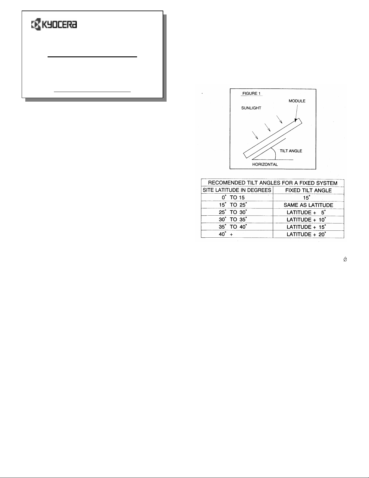
5. MODULE TILT ANGLE
Solar m odules produce the most power when they are
pointed directly at the sun. For installations where the
solar modules are mounted to a permanent structure,
the solar modules should be tilted for optimum winter
perform ance. As a rule, if the system power production
is adequate in the winter, it will be satisfactory during the
rest of the year. The module tilt angle is measured
between the solar modules and the ground (Figure 1) .
6. MOUNTING THE MODULE
The frame of each module has fourteen 7 mm Ú
diamet er mounting holes (Fi gure 2). These are used to
secure the modules to the supporting structure. The
example of a ground mounted structure is shown in
Figure 3. The four holes close to the corners of the
module are most often used for mounting. Clearance
between the module frame and the mounting surface
may be required to prevent the junction box from
touching the surf ace, and to ci rculat e cooli ng air around
the back of the module. In case the modules will be
mounted on the roof or wall of a building, the standoff
method or t he r ac k method are recommended.
STANDOFF: The modules are supported par allel t o the
surface of the building wall or roof. Clearance between
the module frames and surface of the wall or roof is
required to pre- vent wiring dam age and to allow air to
circul ate behind the m odule.
The recommended standoff height is 4.5 i n.
If ot her mounting m eans are employed, thi s may aff ect
the Listing For Fire Class Ratings.
RACK: The supporti ng fram e is used to mount modules
at correct t ilt angles. T he modules are not designed for
integral m ounti ng as part of a r oof or wall. The mounti ng
design may have an impact on the fire resistance.
(about 115 mm)
1
Page 2
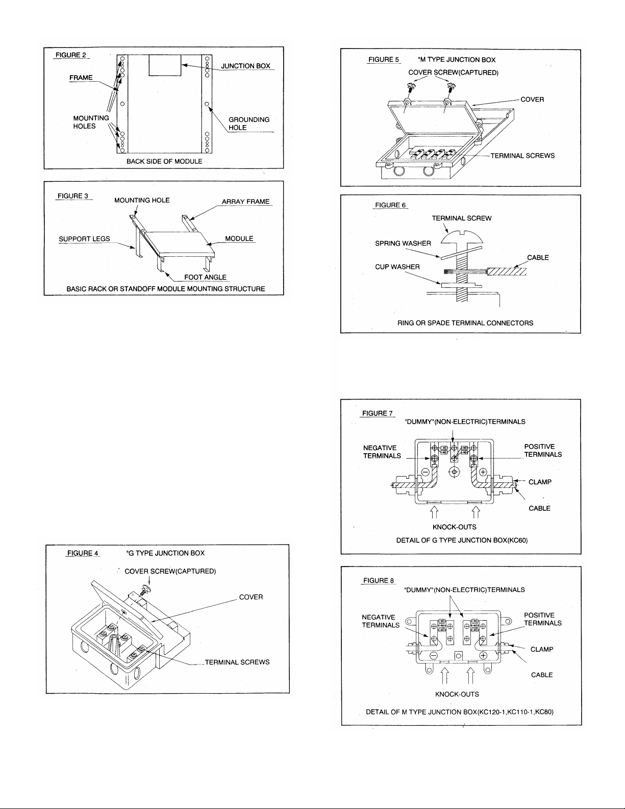
7. WIRING
Most of the larger KYOCERA P OWE R M ODULES use
the "G" or " M " type junction box. This box, on the back
side of the module, is weatherproof and is designed to
be used with standard wiring or conduit connecti ons.
Wiring m ethods should be in accordance to the NEC
(National E lectric al Code). Bypass diodes and cable
clamps are included with each module when shipped
from the factory.
A. Open the "G" or "M" box cover by loosening the
screws in the cover . (Figure 4 and 5)
B. The wire ty pically used to interconnect the solar
modules should be single or two conductor, from 10
AW G(5.26 mm²) up to 14 AWG(2. 08 mm²) gauge
stranded copper wire, i n a " S UNLIGHT RESIS TANT"
jacket UF c able. This cable is suitable for appli c ations
where wiring is exposed to t he direct rays of the sun.
The maximum and minimum diameter of the cabl e that
may be used with the cable connector are 8 mm and 6
mm r espect ively. (Figure 6)
C. Using a flat blade screwdriver, remov e only the
appropriate "K NOCK-OUTS" from the sides of the
"G" or "M" box. (Figure 7 and 8)
2
Page 3

D. Read the enclosed instructions for routing wires
through the knock-outs and clam ps. (Figure 9)
E. Remove approximately ½” of insulation on the ends of
the wires and insert them under the appropriate
"POSITIVE" or "NEGATIVE" terminal screws in the
junction box. The wires should be installed with some
slack; ex c ess wire should be cut off. (Figure 7 and 8)
Install cable with appropriate hardware in accordance
with NEC Article 250 or national and inter national rules.
F. Gently tighten the terminal screws. Do not
overtighten, as the t er minal c an be damaged.
G. The output wiring f rom the f inal m odule is generally
run to a separate array junction box. In commercial
system, this wiring from the array box to the next
component (i.e. fuse box. or charge regulator, etc.) is
generally r un in conduit. T he maxim um electri cal rating
of an accept able series fuse is 4 ~ 12 amperes.
9. BLOCKING DIODES
Blocking diodes can prevent nighttime battery
discharging caused and prevent modules from loss of
array output and being damaged or destroyed by
reverse current flow.
KYOCERA modules do not contain a blocking diode
when shipped from the factory, however most battery
charging regul ators do have this feature.
10. BYPASS DIODES
Partial shading of an individual module in a 12 v olt or
higher "series" string (i.e. two or more modules) can
cause a reverse voltage across the shaded module.
Current is then forced through the shaded area by the
other modules in series.
By hav ing a by pass diode, the forced current will bypass
the shaded module in a series circuit, thereby minimizing
module heat ing and array current losses.
For 12-volt systems and higher: Each solar module
junction box has a diagram illustrating the proper
directi on for the by- pass diode to be install ed between
two of the t erm i nal screws (Figur e 11, F igur e 12). When
the solar modules are connected as individual series
strings first, and then these strings are connected in
parallel , bypass diodes should be used in each juncti on
box. This is the simplest wiring arrangement for most
installations.
At a minimum the bypass diodes must have the following
electrical charact er istics:
)$Y
• Rated Average Forward Current [I
] Above
maximum system current at highest operating
temperat ur e.
• Rated Repetit ive P eak Reverse Voltage [V
UUP
]
Above maxi mum system voltage at lowest
operating temperature.
H. Aft er compl eting the wiri ng between all box es, Close
and secure all the junction boxes.
8. GROUNDING
We recommend you attach all module frames to an earth
ground. Attach a separate ground wire to one of the
extra mounting hol es on the m odule frame wit h a self tapping screw. The rack s must also be grounded unless
they are mechanically connected by nuts and bolts to the
grounded modules.
Grounding is achieved by securing the array f rame for
both roof and field mounted applications. Additionally,
the array frame shall be installed in accordance with
NEC Art 250.
11. MAINTENANCE
Solar modules require v ery little m aintenance. It is not
un- com mon for a remote sit e to be checked but once
per year. Under most conditions, normal rainfall is
suffi ci ent t o keep the m odul e gl ass clean. I f di rt bui l d-up
becomes excessive, clean the glass with a soft cloth
using mild detergent and water. Modules that are
mounted, flat (O
Û WLOW DQJOH VKRXOG EH FOHDQHG PRUH
often, as they will not "self clean" as effectively as
modules m ounted at a 15
Û WLOW RU JUHDWHU 2QFH D \HDU
3
Page 4

check the t ightness of termi nal screws and the general
conditi on of the wiri ng.
Also, check t o be sure that m ounting hardware is tight.
Loose bolts could result in a damaged m odule or array.
12. WARNINGS
Solar modules are live electrical power sources when
ex- posed to light. Arrays of many m odules can cause
lethal shock and burn hazar ds. Sol ar m odul es should be
covered with an opaque material during installation to
avoi d shocks or burns. Do not touch liv e term inals with
bare hands. Use insulated tools for electrical
connections.
PERMIT
- Before installing your solar system, contact local
authorities to determine the necessary permit,
install ation and inspection requirem ents.
INSTALLATION AND OPERATION
• Systems should be installed by qualified
personnel only . The system inv olv es electrici ty,
and can be dangerous if the personnel are not
familiar with the appropriate safety procedures.
• Do not step on the module.
• Although KYO CERA modules are quit e rugged,
the glass can be broken (and the module will no
longer work properly) if it is dropped or hit by
tools or other objects.
• Sunlight shall not be concentrated on the
module.
• The module frames is made of anodized
alumi num, and ther efore corrosion can occur i f
the module is subject to a salt water
envi ronment wit h contact to a rac k of an- other
type of metal. ( E lectroly tic Corrosion)
GROUNDING
• All module fram es and mounting r acks must be
properly grounded in accordance with the
appropriate electrical codes.
INSPECTION
• Follow the requirements of applicable National
and local electrical safety Codes.
BATTERY
• When solar modules are used to charge
batteries, the battery must be installed in a
manner which will prote c t t h e per for ma nce o f th e
system and the safety of its users. The battery
should be away from the main flow of people
and animal traffic. Select a battery site that is
protected f rom sunlight, r ain, snow, debris, and
is well ventilated. Most batteries generate
hydrogen gas when charging, which is
explosive. Do not li ght m atches or cr eate sparks
near the battery bank. When a battery is
installed outdoors, it should be placed in an
insulated and ventilated battery case specifically
designed for t he pur pose.
NOTES The electrical characteristics are within ±10
percent of i ndi cat ed v al ues of l sc, Voc, and Pm ax under
standard test condit ions (irradiance of 1KW/ m², AM 1. 5
spectrum, and c ell temperature of 25
Under conditions, a photov oltaic module is likely to pr o-
duce more curr ent and / or voltage than repor ted at
standard test conditions. Accordingly, the values of lsc
and Voc marked on this module shoul d be multiplied by
a factor of 1.25 when determ ining com ponent voltage
ratings, conductor ampaci ties, fuse sizes, and si z es of
regulators which are connec ted to the PV output. Refer
to Secti on 690- 8 of the National Electrical Code for an
additional multiplying factor of 125 (80 per cent
derating), whic h may also be applicable.
Manufactu red by: Kyocera Corp oration
Made in Japan
Kyocera Solar, Inc.
7812 East Acoma Dr.
Scottsdal e, AZ 85260
Phone: 800-223-9580
480-948-8003
Fax: 480-483-2986
Email: info@kyocerasolar.com
Web site: www.kyocerasolar.com
Û&
4
 Loading...